1
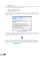
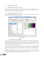
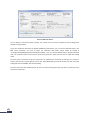
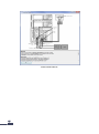
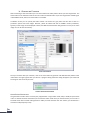
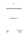
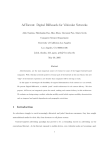
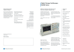
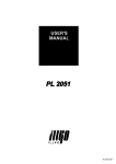
BITIFEYE MHL FRAME GENERATOR USER MANUAL VERSION 1.10 BitifEye Digital Test Solutions GmbH Herrenbergerstrasse 130 71034 Boeblingen, Germany [email protected] www.bitifeye.com TABLE OF CONTENTS I. Installation ...................................................................................................................................................... 3 II. Using the Software .......................................................................................................................................... 4 1. MHL (Mobile High-Definition Link) ............................................................................................................ 4 2. MHL Frame Generator software ................................................................................................................ 4 a. Connecting the instruments ...................................................................................................................... 4 b. Generating Patterns ................................................................................................................................... 7 Audio Signal Generation ................................................................................................................................. 7 Character Synchronization test ....................................................................................................................... 8 c. Adjusting PHY Parameters ......................................................................................................................... 8 d. Adjust Frame Timing Parameters ............................................................................................................... 9 III. Solving Problems / Support...................................................................................................................... 11 I. INSTALLATION Prior to the installation of the MHL Frame Generator software (short “MHL FG” or “software”) ensure that all prerequisites are installed. The required software components are: 1. 2. 3. Agilent IO Libraries Suite 16.2 or higher Agilent ParBERT 81250 Software rev6.32 Microsoft .NET-Framework 2.0 Once these components are installed, install the MHL FG software. Start the installer and click “Next” on the start page. The second page will show the software license agreement. Read it carefully. After accepting it the software can be installed. FIGURE 1: SOFTWARE LICENSE AGREEMENT Once the software is installed, the change-log can be viewed. It lists the changes in the current release. After the installation of the software you will find a shortcut in both the start menu as well as on your desktop. Click on the “MHL Frame Generator” icon to start the software. The software will run for 30 days in demo mode. After that period you have to enter a valid license activation key. If you have purchased the software, send your Site Code and MID displayed during the startup to BitifEye using the e-mail address [email protected]. BitifEye will generate the activation key within 3 business days. II. USING THE SOFTWARE 1. MHL (MOBILE HIGH-DEFINITION LINK) MHL is a digital AV standard that allows transmitting digital video and audio data. The primary purpose is to allow connecting mobile devices such as smart phones to TVs. It therefore utilizes existing connectors (micro USB) on the mobile devices and the HDMI connector on TVs. 2. MHL FRAME GENERATOR SOFTWARE When you start the software the main screen pops up. First, the connection to the instruments should be established. To do this, click on the “Connect…” button. FIGURE 2 MAIN SCREEN a. CONNECTING THE INSTRUMENTS To establish the connection to the instruments you first have to provide the IP address or hostname of the computer on which the ParBERT firmware server is running. If you use “localhost”, the ParBERT firmware server will be started automatically in case it was not yet started earlier. The different clock groups in the ParBERT mainframe are named from left to right starting with DSRA, DSRB, DSRC, DSRD,…. and so on. You should use the appropriate names for your setup. The default setup uses two ParBERT clock groups, one to generate the MHL data signal and one to generate the MHL clock signal. If you check the “Same as Clock” checkbox, only one clock group is used for MHL data and MHL clock. Note that applying intra-pair skew to the MHL signals is only possible with this checkbox checked. In addition to the ParBERT you have to connect the two Signal Generators. These two instruments are used to generate the sinusoidal jitter and are connected by using VISA connection strings. You find the right connection strings by using the Agilent Connection Expert that is part of the Agilent IO Libraries. FIGURE 3 CONNECTION DIALOG You can define a custom termination voltage. This numeric value is used to calculate the actual voltage level applied to the generators. If you have calibration data from the Agilent N5990A test automation, you can use this calibration data in the MHL Frame Generator. You have to select the calibration data folder, which should be located in “C:\ProgramData\BitifEye\ValiFrame\Calibrations\MHL\”. Then you choose between Sink or Dongle calibration data. This calibration data will be used to de-skew the generator output channels and to adjust the voltage levels. Once the proper connection strings are entered you can establish the connection by clicking on the “Connect” button. After that you should typically click on the “Apply MHL Setting and Close” button; this will load initial setting files into the ParBERT and close the dialog. Once the connection was established you will see a connection dialog that shows you how to connect your DUT to the test instruments: FIGURE 4 CONNECTION SETUP b. GENERATING PATTERNS After connecting to the instruments you can start to define the video pattern which you want to generate. The video mode can be selected as well as the color mode and the 3D mode. If you want to generate an MHL signal in PackedPixel mode, select one of the YCbCr 4:2:2 modes. In addition to this you can specify the video content. The choices are gray scale and color bar as well as a parametric option and some images. However, please be aware that due to ParBERT memory limitations, typically no full image can be displayed. Instead, the MHL Frame Generator will generate as many lines of the image as it can fit into the memory. FIGURE 5 MAIN SCREEN Once you are done with your selection, click on the “Set” button to generate and download the pattern to the instruments. During the generation you will see a progress dialog. After this dialog disappears you should see the image on the screen of your DUT. FIGURE 6 GENERATION IN PROGRESS AUDIO SIGNAL GENERATION The generation of audio data is currently only supported for a single video mode, 576p in 24-Bit-per-pixel mode in 2D. To activate the audio transmission, first select this video mode. Once you have done this you can click on the Audio check box to enable audio generation. After you have clicked on the “Set” button, you should hear a constant sound (frequency 1 kHz). CHARACTER SYNCHRONIZATION TEST To generate the pattern for the pattern synchronization, check the “Fill With Null-Packets” option. After you have clicked on the “Set” button, the ParBERT generates the test pattern with the required packet alignments. HDMI 3D COMPATIBILITY There are two compatibility options in the “Edit” menu. The option “Use HDMI Vendor Specific InfoFrame” transmits the Vendor Specific InfoFrame according to the HDMI specification, not according to the MHL specification. If the option “Omit Sub-Frame Separator” is active, Frame-Sequential 3D is transmitted without the sub-frame separator. This means it is transmitted without an additional sync pulse between the left-eye image and the right-eye image, which matches the HDMI specification. Enabling these options can be helpful for debugging dongle DUTs which don’t convert 3D signals properly. LIMITATIONS Some parameter combinations can violate the MHL spec or the ParBERT constraints. In this case, the violated parameter is highlighted in the Parameter/Value List, and the “Set” button is disabled. This can happen e.g. when the MHL data bit rated violates the thresholds that are defined in the MHL specification. The limitation can be resolved by selecting a different color mode or 3D mode. c. ADJUSTING PHY PARAMETERS In the Edit Instrument Parameter Setup you can open the dialog to adjust the PHY parameters. In this dialog you can adjust the data rate of the transmitted signal. You have various options to do this. In addition to directly adjusting the data rate you can adjust the pixel clock frame rate and the deviation as well. Once you change one of these parameter values the related parameter value are adjusted automatically. The second group allows you to modify the voltage levels and the skew. The Intra-Pair-Skew can only be adjusted if you are running a one-system configuration; this can be selected in the connection setup dialog by checking the “use same as clock” check box. The ParBERT clock group used will need at least 4 generators for the Intra-Pair-Skew test. The lower part of the dialog allows injecting and adjusting the sinusoidal jitter that is injected to the data. You can inject up to two SJ components to the clock and the data lanes. The jitter on the clock and data lanes can be independent. To set the modified settings you can either click on the buttons directly in the different groups to only adjust the specific settings or click on the “Apply all Settings” button to apply all parameter values at once. FIGURE 7 PHY PARAMETER SETUP d. ADJUST FRAME TIMING PARAMETERS In the Edit Frame Timing Setup menu item you can open the dialog to adjust the timing parameters of the video frame. You can adjust the size of the video frame itself by modifying the resolution or blanking size. In addition you can adjust the position and length of the H-Sync and V-Sync pulses as well as their polarity. This dialog also allows modifying information in the frame like the video code and the aspect ratio. Once you are done with the changes click the “OK” button and the most changes should be visible in the main screen. After clicking the “Set” button, the pattern is generated by the MHL Frame Generator software and downloaded to the instruments for output. When you change the video mode the settings will be reset. FIGURE 8 FRAME TIMING PARAMETER SETUP III. SOLVING PROBLEMS / SUPPORT If you experience problems with the software, please contact BitifEye by sending a mail to [email protected]. Please provide the version number. It can be found in the Help About menu: FIGURE 9: ABOUT DIALOG