1
5 4 5
5
4
5
M545 V6, JANUARY 2005
1/4 DIN PROCESS CONTROLLER
USER’S MANUAL
Table of Contents
Table of Contents
PAGE
CHAPTER 1
INTRODUCTION ............................................................................... 1
545 Modes ......................................................................................... 2
Order Code, Packaging Information ..................................................... 2
Where To Go Next .............................................................................. 2
Text Formatting in This Manual ............................................................ 2
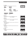
About This Manual:
Throughout this User’s Manual
information appears along the
margins, in the form of NOTEs,
CAUTIONs and WARNINGs, usually
in boldface. Please heed these
safety and good practice notices for
the protection of you and your
equipment.
CHAPTER 2
CONTROLLER OPERATION ............................................................ 5
Displays ............................................................................................. 5
Icons ................................................................................................. 5
Keys .................................................................................................. 6
Basic Operation Procedures ............................................................... 7
Alarm Operation ................................................................................. 8
CHAPTER 3
INSTALLATION AND WIRING ........................................................ 11
Mounting the Controller ..................................................................... 11
Wiring .............................................................................................. 12
AC Power Input ....................................................................... 12
Process Variable Input ............................................................. 13
Digital Input(s) ......................................................................... 16
Remote Setpoint Option ........................................................... 16
Output Modules ....................................................................... 17
Serial Communications ............................................................ 19
CHAPTER 4
HARDWARE CONFIGURATION ..................................................... 21
Hardware Input Types ...................................................................... 21
Accessing and Changing Jumpers .................................................... 23
Adding and Changing Output Modules ............................................... 24
Special Communications Module ...................................................... 26
CHAPTER 5
SOFTWARE CONFIGURATION ...................................................... 27
Menus ............................................................................................. 27
Parameters ...................................................................................... 28
Configuration and Operation ............................................................. 29
Where to Go Next ............................................................................. 29
Text Formatting in This Manual .......................................................... 29
Step-by-Step Guide to Set-Up Parameters ......................................... 30
CONFIG.................................................................................. 30
PV INPUT ............................................................................... 35
CUST. LINR. ........................................................................... 37
CONTROL .............................................................................. 38
ALARMS ................................................................................. 41
REM. SETPT. .......................................................................... 45
RETRANS............................................................................... 46
SELF TUNE ............................................................................ 48
SPECIAL ................................................................................ 49
545 User's Manual
Table of Contents
i
Table of Contents
PAGE
Step-by-Step Guide to Set-Up Parameters (continued)
SECURITY.............................................................................. 51
SER. COMM. .......................................................................... 52
Parameter Value Charts ................................................................... 54
CHAPTER 6
TUNING .......................................................................................... 63
Overview ......................................................................................... 63
TUNING Parameter Guide ................................................................ 64
TUNING Value Chart ........................................................................ 68
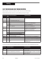
Self Tune Messages and Troubleshooting ......................................... 70
CHAPTER 7
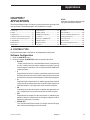
APPLICATIONS .............................................................................. 71
A. Control Type ................................................................................ 71
B. Alarms ......................................................................................... 72
C. Duplex Control ............................................................................. 76
D. Slidewire Position Proportioning Control ........................................ 81
E. Velocity Position Proportioning Control .......................................... 82
F. Staged Outputs ............................................................................ 83
G. Retransmission ............................................................................ 83
H. Digital Inputs ................................................................................ 84
I. Remote Setpoint ............................................................................ 88
J. Multiple Setpoints .......................................................................... 88
K. Multiple Sets of PID Values ........................................................... 89
L. Powerback ................................................................................... 90
M. Self Tune—POWERTUNE® ........................................................................ 90
N. Ramp-to-Setpoint ......................................................................... 96
O. Input Linearization ........................................................................ 97
Thermocouple and RTD Linearization ....................................... 97
Square Root Linearization ........................................................ 97
Custom Linearization ............................................................... 98
P. Load Line ..................................................................................... 98
Q. Security ....................................................................................... 99
R. Reset Inhibition .......................................................................... 100
S. Process Variable Reading Correction .......................................... 100
T. Serial Communications ............................................................... 101
U. Cascade Control ........................................................................ 102
V. Ratio Control .............................................................................. 104
Ratio Control with One Wild Stream ........................................ 104
Ratio Control with Combined Discharge Monitoring .................. 105
W. Feed Forward/Feedback Control ................................................ 107
X. Lag Time .................................................................................... 108
Fixed Lag .............................................................................. 108
Variable Lag .......................................................................... 109
ii
Table of Contents
545 User's Manual
Table of Contents
PAGE
APPENDIX 1
MENU FLOWCHARTS .................................................................. A-1
APPENDIX 2
PARTS LIST .................................................................................. A-3
APPENDIX 3
TROUBLESHOOTING .................................................................. A-5
APPENDIX 4
CALIBRATION .............................................................................. A-7
Preparation for all Input Calibrations ................................................. A-8
Thermocouple Cold Junction Calibration ........................................... A-9
Analog Milliamp Input Calibration ...................................................... A-9
Milliamp Output Calibration ............................................................ A-10
Reset Menu Data .......................................................................... A-11
Hardware Scan ............................................................................. A-12
Slidewire Test ............................................................................... A-12
Quick Calibration Procedure .......................................................... A-12
APPENDIX 5
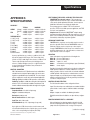
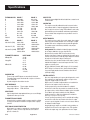
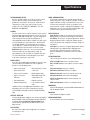
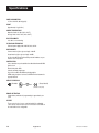
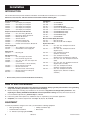
SPECIFICATIONS ........................................................................ A-13
APPENDIX 6
GLOSSARY ................................................................................. A-17
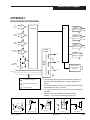
APPENDIX 7
ISOLATION BLOCK DIAGRAM ................................................... A-23
545 User's Manual
Table of Contents
iii
Table of Contents
List of Figures
FIGURE
DESCRIPTION
PAGE
2.1 ................. Operator Interface ............................................................... 5
2.2 ................. Before and After Acknowledging an Alarm ............................ 9
3.1 ................. Instrument Panel & Cutout Dimensions ............................... 11
3.2 ................. Attaching Mounting Collar .................................................. 11
3.3 ................. Terminal Assignments ....................................................... 12
3.4 ................. AC Power Input Terminals ................................................. 13
3.5 ................. Process Variable Terminals ............................................... 13
3.6 ................. PV1 and PV2 Wiring for Milliamp, RTD and Voltage Inputs ... 14
3.7 ................. PV1 and PV2 Wiring for Milliamp Inputs
with Internal and External Power Supply ............................. 15
3.8 ................. Digital Input Wiring with a Switch or Relay ........................... 16
3.9 ................. Digital Input Wiring with an Open Collector .......................... 16
3.10 ............... Remote Setpoint Terminals ................................................ 16
3.11 ............... Mechanical Relay Output Wiring ......................................... 17
3.12 ............... SSR Relay Output Wiring ................................................... 17
3.13 ............... DC Logic Output Wiring ..................................................... 18
3.14 ............... Milliamp Output Wiring ....................................................... 18
3.15 ............... Position Proportioning Output Wiring .................................. 18
3.16 ............... Serial Communications Terminals ...................................... 19
4.1 ................. Location of Printed Circuit Boards ....................................... 21
4.2 ................. The Microcontroller Circuit Board, the Option Board,
and the Power Supply Board .............................................. 22
4.3 ................. Representation of Module .................................................. 25
4.4 ................. Install Communications Module .......................................... 26
5.1 ................. Parts of the Menu Block ..................................................... 27
5.2 ................. Independent vs. Dependent Parameters ............................. 28
5.3 ................. Configuration Flowchart ..................................................... 28
6.1 ................. Access the Tuning Menu Block .......................................... 63
7.1 ................. Alarm Examples ................................................................ 75
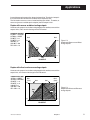
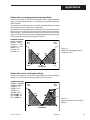
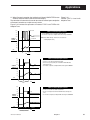
7.2 ................. Duplex With Reverse and Direct Acting Outputs .................. 77
7.3 ................. Duplex With Direct and Reverse Acting Outputs .................. 77
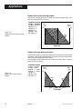
7.4 ................. Duplex With Two Reverse Acting Outputs ........................... 78
7.5 ................. Duplex With a Gap Between Outputs .................................. 78
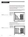
7.6 ................. Duplex With Overlapping Outputs and Output Limits ............ 79
7.7 ................. Duplex With Various Relative Gain Settings ........................ 79
7.8 ................. Duplex With One ON/OFF Output ...................................... 80
7.9 ................. Duplex With Two ON/OFF Outputs ..................................... 80
7.10 ............... Staged Outputs Example ................................................... 83
7.11 ............... Combinations of Closed Digital Inputs ................................. 84
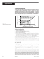
7.12 ............... Pretune TYPE 1, 2 and 3 with Adaptive Tune ....................... 93
7.13 ............... Noise Band Calculation Example ........................................ 94
7.14 ............... Noise Band Values for Temperature Inputs ......................... 95
7.15 ............... Deadtime and Time Constant ............................................. 95
7.16 ............... Square Root Linearization Formula .................................... 97
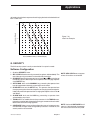
7.17 ............... 15-point Linearization Curve ............................................... 98
iv
Table of Contents
545 User's Manual
Table of Contents
FIGURE
DESCRIPTION
PAGE
7.18 ............... Load Line Example............................................................ 99
7.19 ............... Cascade Control of Product Temperature Functional View............................................................... 102
7.20 ............... Cascade Control of Produce Temperature Wiring View ..................................................................... 103
7.21 ............... The Functions of Cascade Control ................................... 103
7.22 ............... Ratio Control in Mixing Application “Wild Stream” Wiring View ..................................................................... 104
7.23 ............... Ratio Control in Mixing Application “Controlled Stream” Functional View............................................................... 105
7.24 ............... Ratio Control in Mixing Application “Controlled Stream” Wiring View ..................................................................... 106
7.25 ............... Feed Forward Control in Mixing Application Wiring View ..................................................................... 107
7.26 ............... Feed Forward Control in Mixing Application Functional View............................................................... 107
7.27 ............... Fixed and Variable Lag Example Compound Loop Chlorine Control .................................... 108
A4.1 ............... 545 Rear Terminals for Calibration ....................................... 7
A4.2 ............... Flowchart Calibration Menus ............................................... 7
A4.3 ............... Jumper Locations on the Microcontroller Circuit Board .......... 8
A4.4 ............... Input Calibration Wiring ....................................................... 8
A4.5 ............... Thermocouple/Cold Junction Calibration Wiring ................... 9
A4.6 ............... Analog mA Input Calibration Wiring .................................... 10
A4.7 ............... Analog mA Input Jumper Positions ..................................... 10
A4.8 ............... Milliamp Output Calibration Wiring ..................................... 11
A4.9 ............... Output Module Menu Cycle ............................................... 11
A4.10 ............. Slidewire Test Wiring ......................................................... 12
545 User's Manual
Table of Contents
v
Table of Contents
vi
Table of Contents
545 User's Manual
Introduction
CHAPTER 1
INTRODUCTION
From its surge-resistant power supply to its rugged construction, the 545
process controller is designed to ensure the integrity of your process with
maximum reliability — hour after hour, day after day. The isolated inputs
and outputs guard against the dangers of electrical interference, the front
face meets NEMA 4X standards for watertight operation and exposure to
corrosive environments, and the solid metal housing and sturdy rubber keys
enhance durability and ESD protection.
The 545 has been engineered to be the industry’s most user–friendly
process controller. With three digital display areas — two offering up to 9
characters of true alphanumerics — the 545 effectively eliminates the
cryptic messages that could confuse even the most experienced operator.
The bright, crisp display is vacuum fluorescent, and offers much better
readability than any other display technology. Additional operator–friendly
features include: custom programmable alarm messages, illuminated keys,
and an easy to use menu system.
The 545 is the most accurate instrument in its class. With a sampling rate of
eight times per second, it is ideal for demanding pressure and flow applications. The 545 also offers two universal process inputs and modular, field
interchangeable outputs that allow more flexibility than ever before. With
two independent full feature control loops, the 545 can take the place of two
PID controllers; additionally, preprogrammed functions can be called for
cascade, ratio and feed forward applications.
The 545 uses foreground and background loops that facilitate straight
forward operator interface in any of the dual loop modes. It also offers
sophisticated control algorithms, including heuristic adaptive tuning, split
range and duplex outputs (control), and open or closed loop electric actuator control (velocity control).
Thank you for selecting the dual
loop Process Controller. The 545 is
user-configurable for any of the
following functions:
• Two independent PID loops
• Single Station Cascade Control
• Single Station Ratio Control
• Feed Forward Control
Specifications and information subject to change without notice.
545 User's Manual
Chapter 1
1
Introduction
545 MODES
There are three operating modes for the 545 controller:
OPERATION, the default mode of the controller. When the 545 is operating,
you can change setpoints, select manual control and change output level,
acknowledge alarms and monitor conditions.
SET UP, also referred to as configuration. Here you set up the basic functions of the instrument such as input and output assignments, alarm types
and special functions
TUNING, where you configure function parameters for Proportional, Integral
and Derivation (PID) control. Use this mode periodically to optimize the
control performance of the instrument.
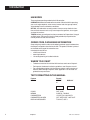
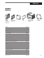
ORDER CODE, PACKAGING INFORMATION
Comparing the product number to the ordering code on page 3 to determine
the outputs and options installed on the 545. The product number is printed
on the label on the top of the controller case.
Included with the 545 are:
• a 545 User’s Manual
• mounting hardware
• 1 sheet engineering unit adhesive labels
WHERE TO GO NEXT
•
•
•
To become more familiar with the 545 interface, continue to Chapter 2.
For important hardware installation guidelines, see Chapters 3 and 4.
For a detailed description of all the software menus and parameters of
the 545, follow through Chapter 5 and 6. Appendix 1 can be used as a
guide to these parameters.
TEXT FORMATTING IN THIS MANUAL
Feature
KEYS
ICONS
MENUS
PARAMETERS
PARAMETER VALUES
DISPLAY MESSAGES
2
Chapter 1
Format
SET PT
or
DISPLAY
SET PT
DISPLAY
OUT, ALM
CONFIG., TUNING,
CYCLE TM:1, MIN.OUT2
OFF, SETPOINT, LAST OUT.
TOO HOT, OUT%
545 User's Manual
Introduction
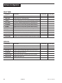
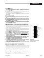
545 –
Output 1: Control
None
Mechanical Relay (5 amp)
Analog (milliamp)
Solid State Relay (triac) (1 amp)
DC Logic (SSR drive)
Output 2: Control, Alarm, or Retransmission
None
Mechanical Relay (5 amp)
Analog (milliamp)
Solid State Relay (triac) (1 amp)
DC Logic (SSR drive)
0
0
Order
Code
0
1
2
3
4
0
1
2
3
4
Output 3: Control, Alarm, Retransmission, or Loop Power
None
0
Mechanical Relay (5 amp)
1
Analog (milliamp)
2
Solid State Relay (triac) (1 amp)
3
DC Logic (SSR drive)
4
Loop Power
5
Output 4: Control, Alarm, Retransmission, or Loop Power
None
0
Mechanical Relay (0.5 amp, 24 V)
1
Analog (milliamp)
2
Solid State Relay (triac) (0.5 amp, 24 V)
3
DC Logic (SSR drive)
4
Loop Power
5
Options
Enter “0” if not desired
Slidewire Feedback for Position
Proportioning Output
24 VAC/24VDC Operation
Slidewire and 24 VAC/24VDC
A
F
G
Remote Setpoint
B
Set of Five Digital Inputs
Certification
Five Digital Inputs and
D
H
J
Certification
Serial Communications
Enter “0” if not desired
RS-485 Serial Communications
S
Note 1: Capability for position proportioning output with slidewire feedback is specifed by ordering 545-11xxAxxx00, 545-33xxAxxx00,
or 545-44xxAxxx00. (Slidewire not required for velocity proportioning.) Note 2: Up to three outputs may be used for alarms. Note 3: All
outputs are interchangeable modules. Note 4: The mechanical relay and solid state relay modules are derated to 0.5 amp at 24 Vac
when used as the fourth output.
545 User's Manual
Chapter 1
3
Introduction
4
Chapter 1
545 User's Manual
Basic Interface
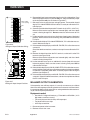
CHAPTER 2
CONTROLLER OPERATION
545
Icons
PV2
OUT
1 2
ALM
1 2
Displays:
1st
2nd
3rd
MANUAL
DISPLAY
ACK
MENU
SET PT
Location for
identification
label
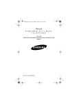
Figure 2.1
Operator Interface
FAST
Keys
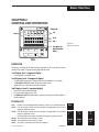
DISPLAYS
The display strategy of the 545 Process Controller is the same for all control
modes: Dual Loop, Cascade, Ratio and Feed Forward.
1st Display (five 7-segment digits)
•
For the process variable value.
2nd Display (nine 14-segment digits)
•
•
•
For the setpoint, deviation, output value or valve position (if available).
In TUNING or SET UP mode, for the parameter name.
Upon power up, indicates the current setpoint.
3rd Display (nine 14-segment digits)
•
•
•
Name of current foreground loop
For alarm messages, errors, etc.
In TUNING or SET UP mode, for the value or choice of parameter shown in
the 2nd display.
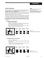
ICONS (LIT)
PV2
Loop 2 is in the foreground (on display); Loop 1 is in the background.
OUT1 For this output, either the relay output is energized or the analog
output is greater than 0%.
OUT2 For this output, either the relay output is energized or the analog
output is greater than 0%.
If control output is analog, indicates the output is greater than 0%.
ALM 1 The respective alarm (one) is active.
ALM 2 The respective alarm (two) is active.
ALM An alarm is active but no output is assigned.
545 User's Manual
Chapter 2
PV2
OUT
1
OUT
2
OUT
1 2
ALM
1
ALM
2
ALM
1 2
5
Basic Interface
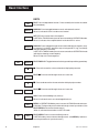
KEYS
FAST
MANUAL
SET PT
DISPLAY
FAST
+
DISPLAY
▲
FAST
+
▲
▼
FAST
+
▼
ACK
MENU
FAST
6
+
MENU
FAST: Has no independent function. Press to modify the function of another
key (see below).
MANUAL: Press to toggle between manual and automatic control.
When lit, indicates the unit is under manual control.
SET PT: Press to select the active setpoint.
In SET UP or TUNING mode, press to return controller to OPERATION mode.
When lit, indicates that a setpoint other than the local SP1 is active.
DISPLAY: Press to toggle through values in the 2nd display for setpoint, ramping setpoint (if available), deviation, output. background PV, lag (if available)
and valve position (if available).
In SET UP or TUNING mode, press to return controller to OPERATION mode
(with display showing current setpoint).
When lit, Loop 2 is in the foreground.
FAST+DISPLAY: Toggles between the background loop and foreground loop.
▲ : Press to increase the value or selection of displayed parameter.
FAST+▲
▲ : Press to scroll through values at a faster rate.
▼ : Press to decrease the value or selection of displayed parameter.
FAST+▼
▼ : Press to scroll through values at a faster rate.
ACK: Press to acknowledge (an) alarm(s).
When lit, indicates there is an acknowledgeable alarm.
MENU : In OPERATION Mode, press to access the TUNING mode and menu.
In Set Up or Tuning mode, press to advance through a menu’s parameters. (Use
FAST+MENU to advance to the next menu.)
When lit, indicates the controller is in SET UP mode.
FAST+MENU: Press to access the Set Up menus.
In SET UP mode, press to advance through menus. (Use MENU by itself to access the parameters of a particular menu.)
Chapter 2
545 User's Manual
Basic Interface
BASIC OPERATION PROCEDURES
A Quick Explanation of Dual Loop Operation
Upon power up, Loop 1 is in the foreground (displayed), and Loop 2 is in the
“background” (hidden). Set up changes only affect the foreground loop; to make
changes to the operation of the background loop, it must be brought to the foreground.
The controller helps the user identify the foreground and background loops with
the following:
• When Loop 2 is in foreground DISPLAY key and the PV2 icon are lit
• The third display will show a message identifying the foreground loop.
Use the following as a quick guide to key operating functions of your 545. Most
of these procedures will affect whichever loop is in the foreground at the time
you execute the procedures. Those that are specified by the word GLOBAL will
affect both loops (the whole controller).
To switch the foreground and background loops
1. Press FAST+DISPLAY.
To select /change a setpoint
1. Use DISPLAY key to toggle display to Set Point.
2. Use SET PT key to toggle to active setpoint.
Before the newly selected setpoint is made active, there is a two-second delay to prevent any disruptive bumps. If the setpoint displayed is ramping,
RAMPING will show the 3rd display.
3. To change value, press ▲ or ▼ .
NOTE:
See the glossary in Appendix 6 for
explanation of ramping and target
setpoint. Also refer to the section in
Chapter 7.
To change from auto to manual control (bumpless transfer)
1. When in automatic control, press the MANUAL key at any time, except while
in the TUNING mode.
2. The MANUAL key will light in red, and the 2nd display will immediately change
to indicate current output level.
To change from manual to auto
1. When in manual control, press MANUAL at any time except while in the
TUNING or SET UP mode.
2. The 2nd display will not change, and the MANUAL key will no longer be lit
once control changes.
To change manual output values
1. Make sure the controller is under manual control.
2. Use the DISPLAY key to toggle 2nd display to output level.
3. Use the ▲ or ▼ key to change the value.
To override security
If a locked operation is attempted, SECURITY appears in the 2nd display for
two seconds.
1. Use the ▲ and ▼ keys to quickly enter the security code, which will show in
the 3rd display. The starting value is 0.
Note: Two seconds of key inactivity will clear the display.
2. If the code is correct, CORRECT appears in the 3rd display. The display will
clear after two seconds, allowing full access.
545 User's Manual
Chapter 2
7
Basic Interface
4. If code is incorrect, INCORRECT appears in the 3rd display. INCORRECT
will disappear after two seconds, and a new security code can then be entered.
5. The controller will revert back to full security lock after one minute of key inactivity.
To display control output value
1. Toggle DISPLAY key until the 2nd display shows OUT followed by the output percentage. This value is the PID output.
• In duplex applications, this value does not directly refer to the output
signal (refer to the Chapter 7 section on Duplex Control for details.)
• For on/off outputs, the output value shown is either ON or OFF.
• For duplex applications with two on/off outputs, the OUT tag is not shown.
In this case, the status of both outputs is shown in the following manner:
1:ON 2:OFF (1 and 2 are the respective outputs).
To display the active PID set
1.
2.
3.
4.
NOTE:
All alarms are software alarms unless
tied to an output relay in the SET UP
mode. See Chapter 5 and Chapter 7 for
more details on alarms.
Select the desired foreground loop (hold FAST, press DISPLAY).
Press MENU to reach Tuning Mode.
In TUNING Mode, press MENU to reach the correct Menu parameter.
The active PID set will have an asterisk (*) on both sides of the value.
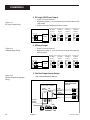
ALARM OPERATION
Alarms may be used in systems to provide warnings of unsafe conditions. All
545 operators must know how the alarms are configured, the consequences of
acknowledging an alarm, and how to react to alarm conditions.
Alarm Indication
Depending on how the system is configured, the 545 indicates an alarm
condition(s) for the foreground loop by:
• Lit icons ALM 1 and/or ALM 2
• Lit ACK key
• Displayed alarm message
The 545 indicates an alarm condition(s) for the background loop by:
• Showing the (user defined) message for one or both alarms in the third display
(alternate displays for simultaneous alarms).
To acknowledge an alarm(s):
An acknowledgeable alarm has both a lit icon and a lit ACK key.
A non-acknowledgeable alarm has only a lit icon.
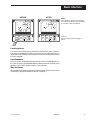
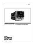
Figure 2.2 demonstrates acknowledging an alarm.
1. If the alarm is in the background, bring that loop forward using
FAST+DISPLAY.
2. To acknowledge Alarm 1, press ACK once.
3. To acknowledge Alarm 2, press ACK twice.
4. If both alarms are activated, press ACK once to acknowledge Alarm 1, then
again to acknowledge Alarm 2.
5. The message and alarm icon disappear.
8
Chapter 2
545 User's Manual
Basic Interface
BEFORE
AFTER
545
OUT
1
ALM
1
545
OUT
1
MANUAL
DISPLAY
ACK
MENU
SET PT
FAST
MANUAL
DISPLAY
ACK
MENU
NOTE:
Powering down the 545 acknowledges/
clears all latched alarms. When powering
up, all alarms will be reinitialized.
SET PT
Figure 2.2
Before and After Acknowledging an
Alarm
FAST
Latching Alarms
If an alarm is set up to be latching (for details, see Chapter 5) then, in general,
it must be acknowledged in order to clear the alarm and release the relay (if
applicable). A non-latching alarm will clear itself as soon as the process leaves
the alarm condition.
Limit Sequence
An alarm can be configured to be both latching and non-acknowledgeable. In
this case, the alarm is acknowledgeable only after the process has left the alarm
condition. This is similar to the function of a limit controller.
More on Alarms
For more details on how to set up alarms and for examples of various ways alarms
can be set up, refer to the section on Alarms in Chapter 7.
545 User's Manual
Chapter 2
9
Basic Interface
10
Chapter 2
545 User's Manual
Installation
CHAPTER 3
INSTALLATION AND WIRING
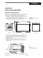
MOUNTING THE CONTROLLER
The 545 front face is NEMA 4X rated (waterproof). To obtain a waterproof
seal between the controller and the panel, follow these directions:
1. The 545 fits in a standard 1/4 DIN cutout. Mount the 545 in any panel
with a thickness from .06 in. to .275 in. (1.5 mm to 7.0 mm).
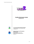
2. Figure 3.1 shows the controller and panel dimensions. The panel cutout
must be precise, and the edges free from burrs and waves.
Figure 3.1
Instrument Panel & Cutout
Dimensions
7.180 (182.37) OVERALL LENGTH
PANEL
1.180 (29.97)
3.770 (95.76)
3.622 (92.00) MIN.
3.653 (92.80) MAX.
3.585 (91.06)
3.622 (92.00) MIN.
3.653 (92.80) MAX.
3.770 (95.76)
545
PV2
OUT
1 2
ALM
1 2
MANUAL
DISPLAY
ACK
MENU
SET PT
FAST
FRONT
BEZEL
GASKET
6.000 (152.40)
CUTOUT
SIDE
3. Place bezel gasket around the controller case (starting at the back of
controller). Then, slide the gasket against the back of the bezel.
4. With the bezel gasket in place, insert the 545 into the panel cutout from
the front of the panel.
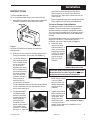
5. Slide the mounting collar over the back of the case, as shown in
Figure 3.2. The collar clip edges will lock with matching edges on the
controller case.
Mounting Clip
Figure 3.2
Attaching Mounting Collar
Front Panel
Mounting Collar
545 User's Manual
Collar Screws (1 of 4)
Chapter 3
11
Installation
CAUTION !
The enclosure into which the 545
Controller is mounted must be
grounded according to CSA
standard C22.2 No. 0.4.
6. Insert the four mounting collar screws from the rear of the collar. Gradually tighten the screws (using a Phillips #2 screwdriver) to secure the
controller against the panel.
7. If there is difficulty with any of the mounting requirements, apply a bead of
caulk or silicone sealant behind the panel around the perimeter of the case.
WARNING!
Avoid electrical shock. Do not
connect AC power wiring at the
source distribution panel until all
wiring connections are complete.
WIRING
Our 545 controllers are thoroughly tested, calibrated and “burned in” at the factory, so the controller is ready to install. Before beginning, read this chapter thoroughly and take great care in planning a system. A properly designed system
can help prevent problems such as electrical noise disturbances and dangerous extreme conditions.
1. For improved electrical noise immunity, install the 545 as far away as possible from motors, relays and other similar noise generators.
2. Do not run low power (sensor input) lines in the same bundle as AC power
lines. Grouping these lines in the same bundle can create electrical noise
interference.
3. All wiring and fusing should conform to the National Electric Code and to
any locally applicable codes.
4. An excellent resource about good wiring practices is the IEEE Standard No.
518-1982 and is available from IEEE, Inc., 345 East 47th Street, New York,
NY 10017, (212) 705-7900.
Diagrams on the next three pages serve as guides for wiring different types of
process inputs. The shaded areas on the diagrams show which rear terminals
are used for that type of wiring.
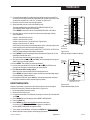
AC Power Input
TOP (as viewed from back of controller)
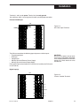
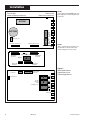
Figure 3.3
Terminal Assignments
Actual 545 device only has top and
bottom numbers of each column of
terminals marked.
WARNING!
Electric Shock Hazard! Terminals 1
and 2 carry live power. DO NOT touch
these terminals when power is on.
WARNING!
Terminal 9 must be grounded to avoid
potential shock hazard, and reduced
noise immunity to your system.
12
DIN
GND
17
25
(NOT
USED)
10 S/W
CCW
DIN 1
18
26
COMM–
3
11 S/W 2
DIN 2
19
27
COMM+
OUT 1+
4
12 S/W 3
DIN 3
20
28
PV2–
OUT 2–
5
13 RSP–
DIN 4
21
29
PV2+
OUT 2+
6
14 RSP+
DIN 5
22
30
RTD 3RD
OUT 3–
7
15 OUT 4–
COLD
JUNC–
23
31
PV1–
OUT 3+
8
16 OUT 4+
COLD
JUNC+
24
32
PV1+
LINE
1
9
NEUTRAL
2
OUT 1–
Chapter 3
EARTH
GND
545 User's Manual
Installation
Terminals 1 and 2 are for power. Terminal 9 is the earth ground.
Use a 0.5 Amp, 250 V, fast-acting fuse in line with your AC power connection.
Process Variable Input
TOP
POWER
1
9
2
EARTH/
GROUND
17
25
10
18
26
3
11
19
27
4
12
20
28
5
13
21
29
6
14
22
30
7
15
23
31
8
16
24
32
Figure 3.4
AC Power Input Terminals
Screws must be tight to ensure good electrical connection
The 545 accommodates the following types of process variable inputs:
• Thermocouple Input
• RTD Input
• Voltage Input
• Milliamp Input with External Power Supply
• Milliamp Input with Internal Power Supply
Each type of input can be wired for PV1 (terminals 31 and 32) or for PV2 (terminals 28 and 29).
CAUTION!
Do not run low power (sensor input)
lines in the same bundle as AC power
lines. Grouping these lines in the same
bundle can create electrical noise
interference.
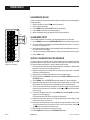
Digital Input(s)
TOP
Figure 3.5
Process Variable Terminals
1
9
17
25
2
10
18
26
3
11
19
27
4
12
20
28
PV 2–
5
13
21
29
PV 2+
6
14
22
30
RTD 3rd
7
15
23
31
PV 1–
8
16
24
32
PV 1+
Screws must be tight to ensure good electrical connection
545 User's Manual
Chapter 3
13
Installation
NOTE:
Typically, in the U.S., negative leads
are red.
For PV1
THERMOCOUPLE INPUT
30
Figure 3.6
PV1 and PV2 Wiring for Milliamp,
RTD and Voltage Inputs.
31
32
For PV2
THERMOCOUPLE INPUT
–
28
+
29
2-WIRE RTD
–
+
2-WIRE RTD
Jumper wire
28
RTD
29
30
30
31
RTD
32
Jumper wire
3-WIRE RTD
3-WIRE RTD
Same color
Third leg
of RTD
Same
color
28
RTD
29
30
30
31
Third leg of RTD
32
4-WIRE RTD
4-WIRE RTD
Same color
Same color
30
Third leg
of RTD
28
31
29
32
30
Same color
Third leg
of RTD
DO NOT connect 4th leg
VOLTAGE INPUT
31 –
32 +
14
Chapter 3
–
+ Transmitter
Do NOT
connect
4th leg
VOLTAGE INPUT
28 –
29 +
–
+ Transmitter
545 User's Manual
Installation
For PV1
For PV1
MILLIAMP INPUT
MILLIAMP INPUT
2-wire transmitter with
separate power supply
2-wire transmitter with
separate power supply
– External
28
Power Supply
29
+
– Transmitter +
31
– External
+
– Transmitter
+
Power Supply
32
MILLIAMP INPUT
MILLIAMP INPUT
2-wire transmitter with
loop power supply
2-wire transmitter with
loop power supply
15
16
–
–
+
+
2-wire
transmitter
15
16
–
–
+
+
31 –
28 –
32 +
29 +
2-wire
transmitter
MILLIAMP INPUT
MILLIAMP INPUT
4-wire transmitter with
loop power supply
4-wire transmitter with
loop power supply
–
–
16 +
+
15
Input power
for transmitter
–
–
16 +
+
15
– 4-20 mA output
+ from transmitter
NOTE:
To use loop power, there must be a
loop power module is installed in the
3rd or 4th output socket. Compare the
controller product number with the
order code in Chapter 1 to determine
if the 545 has a loop power module
installed. To install a loop power
module, refer to Chapter 4.
Input power
for transmitter
– 4-20 mA output
+ from transmitter
31 –
28 –
32 +
29 +
545 User's Manual
Figure 3.7
PV1 and PV2 Wiring for Milliamp
Inputs with Internal and External
Power Supply
Chapter 3
15
Installation
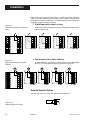
Digital inputs can be activated in three ways: a switch (signal type), closure of
a relay, or an open collector transistor. Digital inputs are only functional when
that option is installed (via hardware). The controller detects the hardware and
supplies the appropriate software menu.
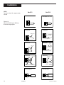
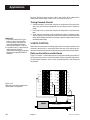
1. Digital Inputs with a switch or relay
Figure 3.8
Digital Input Wiring with a Switch or
Relay
Wire the switch/relay between terminal 17 and the specific digital input
terminal (Figure 3.8).
1
9
DIN
GND
17
25
DIN
GND
17
25
DIN
GND
17
25
DIN
GND
17
25
DIN
GND
17
25
2
10
DIN 1
18
26
DIN 1
18
26
DIN 1
18
26
DIN 1
18
26
DIN 1
18
26
3
11
DIN 2
19
27
DIN 2
19
27
DIN 2
19
27
DIN 2
19
27
DIN 2
19
27
4
12
DIN 3
20
28
DIN 3
20
28
DIN 3
20
28
DIN 3
20
28
DIN 3
20
28
5
13
DIN 4
21
29
DIN 4
21
29
DIN 4
21
29
DIN 4
21
29
DIN 4
21
29
6
14
DIN 5
22
30
DIN 5
22
30
DIN 5
22
30
DIN 5
22
30
DIN 5
22
30
7
15
23
31
8
16
24
32
Screws must be tight to ensure electrical connection
2. Digital Inputs with an Open Collector
Figure 3.9
Digital Input Wiring with an Open
Collector
An open collector is also called a transistor. Wire the transistor between
terminal 17 and the specified digital input terminal (Figure 3.9)
1
9
DIN
GND
17
25
DIN
GND
17
25
DIN
GND
17
25
DIN
GND
17
25
DIN
GND
17
25
2
10
DIN 1
18
26
DIN 1
18
26
DIN 1
18
26
DIN 1
18
26
DIN 1
18
26
3
11
DIN 2
19
27
DIN 2
19
27
DIN 2
19
27
DIN 2
19
27
DIN 2
19
27
4
12
DIN 3
20
28
DIN 3
20
28
DIN 3
20
28
DIN 3
20
28
DIN 3
20
28
5
13
DIN 4
21
29
DIN 4
21
29
DIN 4
21
29
DIN 4
21
29
DIN 4
21
29
6
14
DIN 5
22
30
DIN 5
22
30
DIN 5
22
30
DIN 5
22
30
DIN 5
22
30
7
15
23
31
8
16
24
32
Screws must be tight to ensure electrical connection
Remote Setpoint Option
Use terminals 13 and 14 to connect the remote setpoint signal.
–
Source +
Figure 3.10
Remote Setpoint Terminals
16
Chapter 3
–
+
13
14
545 User's Manual
Installation
OUTPUT MODULES
The 545 output modules are used for control, alarms and retransmission. The
four output module types are: Mechanical Relay, Solid State Relay (Triac),
DC Logic (SSR Drive) and Analog (Milliamp).
To install these modules, plug them into any of the four output sockets on the
printed circuit boards (refer to Chapter 4). The wiring is the same whether the
modules are used for control, alarm or retransmission.
The diagrams on the next two pages are a guide for properly connecting the
various outputs. To find out which module(s) have been installed in the controller, compare the product number on the controller label with the section Order
Code in Chapter 1. This section also includes a diagram of how to wire a position proportioning output, a special application using two mechanical or two solid
state relays.
NOTE:
Refer to Figure 4.2 for location of the
corresponding jumpers.
Second input jumper connector on the
option board must be in either mA
(milliamp) or V (voltage) position.
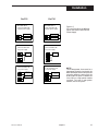
1. Mechanical Relay Output
•
•
•
Output 1 is always Control 1.
Outputs 1, 2 and 3 are jumper selectable for normally open and normally closed on the power supply circuit board.
Output 4 is always configured for normally open and has reduced
voltage and current ratings (see Specifications).
Terminals used Terminals used Terminals used
with Output
with Output
with Output
Module 1
Module 2
Module 3
Line Power
3
Terminals used
with Output
Module 4
3
5
7
15
4
6
8
16
Load
4
Figure 3.11
Mechanical Relay Output Wiring
Recommend use of both MOV and snubber
2. Solid State Relay (Triac) Output
•
•
•
Output 1 is always Control 1.
Respective jumper J1, J2 or J3 must be set to normally open for SSR
(Triac) output.
Output 4 is always configured for normally open and has reduced
voltage and current ratings (see Specifications).
Terminals used Terminals used Terminals used Terminals used
with Output
with Output
with Output
with Output
Module 1
Module 2
Module 3
Module 4
Line Power
3
4
+
-
3
5
7
15
4
6
8
16
Load
+
Figure 3.12
SSR Relay Output Wiring
Recommend use of both MOV and snubber
545 User's Manual
Chapter 3
17
Installation
3. DC Logic (SSR Drive) Output
•
•
Figure 3.13
DC Logic Output Wiring
•
Output 1 is always Control 1.
Respective jumper J1, J2 or J3 must be set to normally open for DC
Logic output.
Output 4 is always configured for normally open.
Terminals used Terminals used Terminals used
with Output
with Output
with Output
Module 1
Module 2
Module 3
3
_
_
3
5
7
15
4
6
8
16
Load
+
4
Terminals used
with Output
Module 4
+
4. Milliamp Output
•
•
Figure 3.14
Milliamp Output Wiring
Output 1 is always Control 1.
Respective jumper J1, J2 or J3 must be set to normally open for
Milliamp output.
Terminals used Terminals used Terminals used
with Output
with Output
with Output
Module 1
Module 2
Module 3
Terminals used
with Output
Module 4
_
3
+
4
3
5
7
15
4
6
8
16
Load
5. Position Proportioning Output
Figure 3.15
Position Proportioning Output
Wiring
(with or without Slidewire Feedback)
POSITION
PROPORTIONING
OUTPUT
Electric Motor Actuator
CCW
CW
Winding Winding
CCW
Slidewire
Wiper
0–1050 Ohm
CW
10
11
12
Actuator
Supply
Current
3
COM
18
Chapter 3
4
5
CCWCOM
6
CW
545 User's Manual
Installation
•
•
•
Mechanical relay or solid state relay modules must be installed in
output sockets 1 and 2.
When using velocity control (no slidewire feedback), there are no connections at terminals 10, 11 and 12.
Use of the slidewire feedback is optional
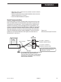
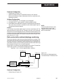
Serial Communications
A twisted shielded pair of wires should be used to interconnect the host and
field units. Belden #9414 foil shield or #8441 braid shield 22-gauge wire are
acceptable for most applications. The foil shielded wire has superior noise
rejection characteristics. The braid shielded wire has more flexibility. The
maximum recommended length of the RS 485 line is 4000 feet. Termination
resistors are required at the host and the last device on the line. Some RS
485 cards/converters already have a terminating resistor. We recommend
using RS-232/RS-485 converter (Product #500-485). The communication
protocol is asynchronous bidirectional half-duplex, hence the leads are
labelled Comm + and Comm –.
Figure 3.16
Serial Communications Terminals
545
Terminals
PC
or other host
Twisted, shielded
RS-485
port
Comm –
26
Comm +
27
To "Comm –" terminal of
next Moore Industries device
To "Comm +" terminal of
next Moore Industries device
Use a 60 to 100 Ohm terminating resistor
connected to the two data terminals of
the final device on the line.
CAUTION
The shield needs to be connected continuously
but only tied to one ground at the host.
Failure to follow these proper wiring practices
could result in transmission errors and other
communications problems.
545 User's Manual
Chapter 3
19
Installation
20
Chapter 3
545 User's Manual
Hardware Configuration
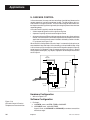
CHAPTER 4
HARDWARE CONFIGURATION
Hardware configuration determines the available outputs as well as the type of
input signal. The 545 controller comes factory set with the following:
• All specified module and options installed (for details, refer to the Order Code
in Chapter 1).
• Process variable and remote setpoint set to accept a milliamp input.
• Relay outputs set to normally open.
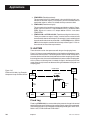
Alter the factory configuration of the 545, requires accessing the circuit boards,
and locating the jumpers and output modules (see Figure 4.1).
1. With the power off, loosen the four front screws, and remove them.
2. Slide chassis out of the case by pulling firmly on the bezel.
FRONT FACE
NOTE:
Hardware configuration of the
controller is available at the factory;
Consult an application engineer for
details.
MIC
BO ROCO
ARD
NTR
OLL
ER
POW
BOA ER SUP
RD
PLY
Figure 4.1
Location of Printed Circuit Boards for
Hardware Configuration
OPTION BOARD
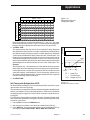
A detailed view of the circuit boards appears in Figure 4.2.
After configuring the hardware, or if no changes are necessary, continue setting
up the process as needed.
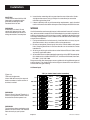
HARDWARE INPUT TYPES
The Process Variable
The 545 accepts several different types of process variable signals. Set a jumper
location to specify the type of input signal. Set the signal range in the software
(see Chapter 5 for software menus, or Chapter 7 for applications).
The jumpers for the process variable are located on the Microcontroller Circuit
Board (see Figure 4.2). The factory default is Milliamp. Locations are marked
as follows:
V
Voltage
MA
Milliamp
TC ▼
Thermocouple with downscale burnout
TC ▲
Thermocouple with upscale burnout
RTD
RTD
545 User's Manual
Chapter 4
NOTE:
Thermocouple downscale and
upscale burnout offers a choice in
which direction the controller would
react in the event of thermocouple
failure. For example, in heat
applications, typically, it is desirable
to fail upscale (TC ▲) so that the
system does not apply more heat.
21
Hardware Configuration
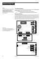
NOTE:
Changing the jumpers means moving
the jumper connector. The jumper
connector slips over the pins,
straddling two rows of pins. The
printed circuit boards are labeled next
to the jumpers.
The Remote Setpoint
Figure 4.2 shows the location of the remote setpoint jumper. The factory default is milliamp. Choose from the following settings:
V Remote setpoint with voltage signal (jumper removed)
mA
Remote setpoint with milliamp signal (jumper installed)
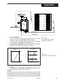
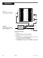
Mechanical Relays
There are three output module sockets on the Power Supply Circuit Board, and
one output module on the Option Board (see Figure 4.2). The mechanical relay
on the Power Supply Board may be configured for either normally open (NO) or
normally closed (NC). A jumper located next to each socket determines this configuration. All relay output are factory set to NO (normally open).
P1
EPROM
P2
Figure 4.2
(from the top) The Microcontroller
Circuit Board, the Option Board, and
the Power Supply Board
V
MA
TC ▼
TC ▲
RTD
5-Pin Connector
Female 22-Pin Connector
Female 22-Pin Connector
PV1
BATTERY
2ND
TB2
V
MA
TC ▼
TC ▲
RTD
TB1
Remote Setpoint Jumper
Male 22-Pin
Connector
Output 4
Male 22-Pin
Connector
4
Male 34-Pin
Connector
5-Pin Connector
Module
Retention
Plate
over Outputs 1,2,3
3
2
1
NO J1 NC NO J2 NC NO J3 NC
Female 34-Pin Connector
Jumpers
NO and NC
22
Chapter 4
545 User's Manual
Hardware Configuration
ACCESSING AND CHANGING JUMPERS
Follow these instructions to change jumpers for the Process Variable, Remote
Setpoint and Digital Inputs:
Equipment needed:
Needle-nose pliers (optional)
Phillips screwdriver (#2)
Wrist grounding strap
1. With power off, loosen two front screws, and remove them.
2. Side the chassis out of the case by pulling firmly on the bezel.
3. Use Figure 4.2 to locate the jumper connector to change.
4. Using the needle nose pliers (or fingers), pull straight up on the connector
and remove it from its pins, as shown in Photo 2. Be careful not to bend the
pins.
Caution!!
Static discharge can cause damage
to equipment. Always use a wrist
grounding strap when handling
electronics to prevent static
discharge.
2. Remove Jumpers
5. Find the new location of the jumper connector (again, refer to Figure 3.2).
Carefully place it over the pins, then press connector straight down. Make
sure it is seated firmly on the pins.
6. Make any other jumper changes as needed. To alter output modules 1,
please refer to the next section, starting with Step #3.
7. To reassemble the controller, properly orient the chassis with board opening on top. Align the circuit boards into the grooves on the top and bottom of
the case. Press firmly on the front face assembly until the chassis is all the
way into the case.
If it is difficult to slide the chassis in all the way, make sure the screws have
been removed (they can block proper alignment), and that the chassis is
properly oriented.
8. Carefully insert and align screws. Tighten them until the bezel is seated firmly
against the gasket. Do not overtighten.
545 User's Manual
Chapter 4
23
Hardware Configuration
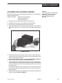
ADDING AND CHANGING OUTPUT MODULES
The 545 has provisions for four output modules. A controller ordered with output
module options already has the modules properly installed. Follow these instructions to add modules, change module type(s) or change module location(s).
Equipment needed:
Wrist grounding strap
Phillips screwdriver (#2)
Small flat blade screwdriver
Wire cutters
1. With power off, loosen two front screws, and remove them.
2. Slide the chassis out of the case by pulling firmly on the bezel.
3. Use a flat screwdriver to carefully pry apart the clips that hold the front face
assembly to the chassis, as in Photo 3. Separate the printed circuit board
assembly from the front face assembly. Use care not to break the clips or
scratch the circuit boards.
4. As shown in Photo 4, carefully pry apart, using hands or a small flat screwdriver, the smaller Option board and the Power Supply board (the one with
3 modules).
5. To change modules 1, 2 or 3:
Output modules 1, 2, and 3 are firmly held in place by a retention plate and
tie wrap. Carefully snip the tie wrap with a wire cutter. To prevent damage to
the surface mount components, ALWAYS snip the tie wrap on TOP of the
Retention Plate, as shown in Photo 5.
Remove the retention plate.
3. Pry Clips
24
4. Separate Boards
Chapter 4
5. Remove Retention Plate
545 User's Manual
Hardware Configuration
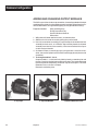
6. To change module 4:
Output Module 4 (on the Option board) is also held in place by a tie wrap.
Snip tie wrap to remove module as shown in Photo 6.
7. Figure 4.3 shows a representation of an output module. Inspect the
module(s) to make sure that the pins are straight.
8. To install any module, align its pins with the holes in the circuit board, and
carefully insert the module in the socket. Press down on the module until it
is firmly seated; refer to Photo 7.
Figure 4.3
Representation of Module
6. Snip Tie Wrap
7. Add/Change Module
9. Replace tie wraps for all the modules (the Retention Plate and Output Module 4) with new ones before reassembling the controller.
Failure to use the tie wraps may result in loosening of the module and eventual failure. All separately ordered modules should come with a tie wrap. Extra
sets of tie wraps are available by ordering Part #545-665.
NOTE: For greatest accuracy, calibrate all milliamp modules added for
retransmission as per the instructions in Appendix 2.
10. Rejoin the circuit boards by aligning the pins of their connectors, then squeezing the board(s) together. Make sure that all three printed circuit boards are
properly seated against one another; check along side edges for gaps. Make
sure the cable assemblies are not pinched.
11. To reattach the board assembly to the front face assembly, align the boards
(with the open area on top) into the slots of the font face assembly. The clips
should snap into place.
12. To reassemble the controller, properly orient the chassis with board opening on top. Align the circuit boards into the grooves on the top and bottom of
the case. Press firmly on the front face assembly until the chassis is all the
way into the case.
If it is difficult to slide the chassis in all the way, make sure the screws have
been removed (they can block proper alignment), and that the chassis is
properly oriented.
13. Carefully insert and align screws. Tighten them until the bezel is seated firmly
against the gasket. Do not overtighten.
545 User's Manual
Chapter 4
25
Hardware Configuration
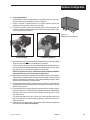
SPECIAL COMMUNICATIONS MODULE
A special communications module is available for the 545; see order code in
Chapter 1 for details.
Equipment needed:
Wrist grounding strap
Phillips screwdriver (#2)
Small flat blade screwdriver
1. Before installing the communications module, set up the hardware wiring
for the application. See Chapter 4 for details.
2. With power off, loosen two front screws, and remove them.
3. Slide the chassis out of the case by pulling firmly on the bezel. Do not detach
the board assembly from the front face of the controller.
4. Orient the Communications Module as shown, and attach it to Connectors
P1 and P2 as shown in Figure 4.4.
Insert module onto connectors
Front of controller
(circuits boards still attached to front face)
P1
EPROM
Figure 4.4
Install Communications Module
onto Microcontroller Board
P2
BATTERY
REMOTE SP
CONFIGURATION
V
MA
TCt
TCs
RTD
2ND
TB2
5. To reassemble the controller, properly orient the chassis with board opening
on top. Align the circuit boards into the grooves on the top and bottom of the
case. Press firmly on the front face assembly until the chassis is all the way
into the case.
If it is difficult to slide the chassis in all the way, make sure the screws have
been removed (they can block proper alignment), and that the chassis is
properly oriented.
6. Carefully insert and align screws. Tighten them until the bezel is seated firmly
against the gasket. Do not overtighten.
26
Chapter 4
545 User's Manual
Software Configuration
CHAPTER 5
SOFTWARE CONFIGURATION
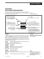
The software configuration menus of the 545 contain user-selected variables that
define the action of the controller. Read through this section before making any
parameter adjustments to the controller.
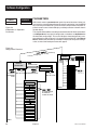
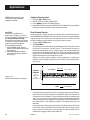
When initially setting up the
controller, cycle through all the
parameters in each Menu.
Press the MENU+FAST to
advance to the next menu.
This is a Menu.
Its name will show in the 2nd display.
press:
MENU/FAST
Press MENU to advance to the
next parameter (this also sets
the value for the current
parameter. Use arrow keys to
select a value).
Use the arrows keys to
enter numerical values,
and/or move through the
selection group.
CONFIG.
press:
MENU
press:
This is a menu Parameter.
The name shows in the 3rd display.
In this manual, independent parameters
appear as white text on black, and
dependent parameters appear as black
INDICATOR
(D)
press MENU/FAST
Go to next Menu Block:
This is a parameter Value.
These values appear in the 3rd display,
replacing the parameter name.
In this manual, parameter graphics
indicate the default (factory) setting.
If the default value is dependent on other
variables, (D) is shown.
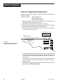
MENUS
In SETUP mode, there are 12 sets of options that control different aspects of 545
operation; in TUNING mode, there is one. Each set of options is called a menu.
When traversing the two modes, the menu names appear in the 2nd display.
Most of the menus are loop dependent, that is, each loop has its own set of
parameters for that menu. Three of the menus are global, that is, one set of
parameters applies to both loops.
CONFIG
(Global) Mode selection and input/output hardware assignments
PV INPUT
Process variable input options
CUST. LINR. Linearization curve options for PV input.
CONTROL
Control options
ALARMS
Alarm options
REM. SETPT. (Global) Controller remote setpoint options
RETRANS.
(Global) Retransmission output options
SELF TUNE Self tune algorithm options
SPECIAL
Special feature options
SECURITY
(Global) Security functions
SER.COMM. (Global) Serial Communications options (requires comm. board)
and
TUNING
Tuning parameters configuration (see Chapter 6)
545 User's Manual
Figure 5.1
Parts of the Menu Block
Chapter 5
CAUTION!
All software changes occur in real time;
always perform set up functions under
manual operation.
NOTE:
For information about the Tuning
menu/mode, refer to Chapter 6. For
more information about set up
parameters and 545 applications,
refer to Chapter 7.
27
Software Configuration
TUNE PT.
CONTACT 1
AUTOMATIC
MANUAL
PARAMETERS
Within each menu are parameters for particular control functions. Select values for each parameter depending on the specific application. Use the MENU
key to access parameters for a particular menu; the parameter name will replace the menu name in the 2nd display, and the parameter value will show in
the 3rd display.
This chapter outlines all the available parameters for the 545. Some parameters
are independent of any special configuration, and others are dependent on
the individual configuration. This manual displays these two types of parameters differently; refer to Figure 5.2. A special feature of the 545, called Smart
Menus, determines the correct parameters to display for the specific configuration, so not all the listed parameters will appear.
Figure 5.2
Independent vs. Depedent
Parameters
Figure 5.3
Configuration Flowchart
ISPLAY
op
FAST+D
played lo
op to dis
lo
d
n
u
ro
backg
to move
MANUAL
OPERATION
for
TUNING mode
TUNING
MANUAL
OPERATION
or
to return to
OPERATION
mode
for
TUNING mode
+
for Loop 2
SET UP mode
SET UP
CONFIG
TUNING
+
or
for
Loop
1
for
or
to return to SET UP mode OPERATION mode
OPERATION
mode
or
+
for Loop 2
for
SET UP OPERATION mode
mode
PV INPUT
CUST. LINR.
+
for Loop 1
SET UP mode
CONTROL
+
to toggle through
menu blocks
in SET UP mode
ALARMS
REM. SETPT.
RETRANS.
SELF TUNE
SET UP
SPECIAL
CONFIG
SECURITY
PV INPUT
LOOP 2
CUST. LINR.
CONTROL
SER. COMM.
+
to toggle through
menu blocks
in SET UP mode
ALARMS
REM. SETPT.
RETRANS.
SELF TUNE
SPECIAL
SECURITY
SER. COMM.
LOOP 1
28
Chapter 5
545 User's Manual
Software Configuration
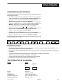
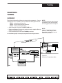
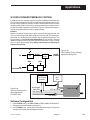
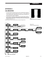
CONFIGURATION AND OPERATION
Figure 5.3 shows the relationships among the different modes of the 545 and
the configuration menus:
• Parameter changes can only be made to the loop in the foreground
(Loop 1 upon power up). To bring the background loop into the foreground
to view and make changes, hold down FAST and press DISPLAY.
• SET UP menus can only be accessed from manual control. To transfer the
545 from automatic to manual control, press MANUAL.
• To access the SET UP menus, hold down FAST and press MENU. The
MENU key will illuminate; and CONFIG will appear in the 2nd display.
• To access the parameters for a particular menu, press MENU.
• To select a parameter value, use ▲ and ▼ . Press MENU to advance to the
next parameter, or FAST+MENU to advance to the next menu.
• To advance to the next menu, press FAST+MENU.
• TUNING mode (and the TUNING menu) can be accessed from either automatic or manual control. To access the tuning menu, press MENU .
• To return controller to manual control, press DISPLAY or SET PT.
A key to these functions (as shown below) appears at the bottom of every page
in the menu section of this chapter.
Access Set Up
FAST
+
MENU
Next menu
Next parameter
+
MENU
FAST
MENU
Next value
▲
Access Tuning
▼
MENU
Return to Operation
DISPLAY
Switch Loops
FAST
+ DISPLAY
WHERE TO GO NEXT
•
•
•
•
•
•
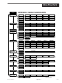
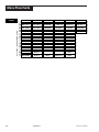
For information about all the software menus and parameters, continue reading this chapter. Refer to Appendix 1 for a
quick-reference flowchart of all menus and parameters.
For information about the installed options on the 545, compare the product label on top of the controller to the order code
in Chapter 1.
To mount the controller and configure the wiring of the 545 for inputs and outputs, see Chapter 3.
To alter the output module and jumper configuration, see Chapter 4.
For more information about the Tuning function of the 545, see Chapter 6.
For more information about application for the 545, see Chapter 7.
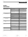
TEXT FORMATTING IN THIS MANUAL
Feature
KEYS
Format
SET PT
or
SETPT
ICONS
MENUS
PARAMETERS
PARAMETER VALUES
DISPLAY MESSAGES
545 User's Manual
DISPLAY
DISPLAY
OUT, ALM
CONFIG., TUNING,
CYCLE TM:1, MIN.OUT2
OFF, SETPOINT, LAST OUT.
TOO HOT, OUT%
Chapter 5
29
Software Configuration
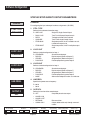
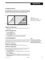
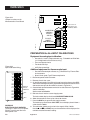
STEP-BY-STEP GUIDE TO SETUP PARAMETERS
CONFIG.
CONFIG.
For configuring the input and output hardware assignments. (GLOBAL)
1. CTRL. TYPE
CTRL. TYPE
Defines the fundamental controller setup.
ONE LOOP
D
•
•
•
•
ONE LOOP
DUAL LOOP
RATIO
CASCADE
FFWD.SUM
•
FFWD.MULT
Single PV, Single Control Output
Two PV, with Control Output for each
Two loops with Set Points rationed
Two PV with single Control Output
Single loop control, 2nd PV added to or subtracted from output value
Single loop control, 2nd PV multiplies output
value
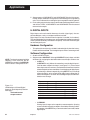
2. LOOP1 OUT
LOOP1 OUT
STANDARD
Defines standard configuration for Loop 1.
D
•
•
•
STANDARD
DUPLEX
STAGED
POS.PROP.
Standard control output
Duplex outputs (Refer to Chapter 7)
Staged outputs (Refer to Chapter 7)
Position proportioning control output
3. LOOP2 OUT
LOOP2 OUT
Defines standard configuration for Loop 2.
STANDARD
D
•
•
•
•
STANDARD
DUPLEX
STAGED
POS.PROP.
NONE
Standard control output
Duplex outputs (Refer to Chapter 7)
Staged outputs (Refer to Chapter 7)
Position proportioning control output
Allows second loop to function as an indicator
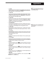
4. LINE FREQ
LINE FREQ.
Specifies the power source frequency
D 60 Hz
• 50 Hz
60 HZ
5. OUTPUT:2
OUTPUT:2
Defines the function of the second output.
D
•
•
•
•
OFF
Access Set Up
FAST
30
+
MENU
OFF
ALM.RLY:ON
ALM.RLY:OFF
RETRANS.
COMM. ONLY
Next menu
Next parameter
+
MENU
FAST
MENU
Chapter 5
Completely deactivates output
Retransmission
Output addressable only through communications
Next value
▲
▼
Access Tuning
Return to Operation
MENU
DISPLAY
Switch Loops
FAST
+
DISPLAY
545 User's Manual
Software Configuration
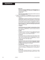
6. OUTPUT:3
OUTPUT:3
Off
Defines the function of the third output.
D
•
•
•
•
OFF
ALM.RLY:ON
ALM.RLY:OFF
RETRANS.
COMM. ONLY
Completely deactivates output
Retransmission
Output addressable only through communications
7. OUTPUT:4
OUTPUT:4
Defines the function of the fourth output.
D
•
•
•
•
OFF
ALM.RLY:ON
ALM.RLY:OFF
RETRANS.
COMM. ONLY
OFF
Completely deactivates output
Retransmission
Output addressable only through communications
8. ANLG. RNG.:1
Defines the output signal for the first output.
D
•
•
•
ANLG.RNG.:1
4-20mA
4–20mA
0–20mA
20-4mA
20-0mA
9. ANLG. RNG.:2
ANLG.RNG.:2
Defines the output signal for the second output.
D
•
•
•
4–20mA
0–20mA
20-4mA
20-0mA
4-20mA
10. ANLG. RNG.:3
Defines the output signal for the third output.
D
•
•
•
ANLG.RNG.:3
4–20mA
0–20mA
20-4mA
20-0mA
4-20mA
11. ANLG. RNG.:4
ANLG.RNG.:4
4-20mA
Defines the output signal for the fourth output.
D
•
•
•
4–20mA
0–20mA
20-4mA
20-0mA
Access Set Up
FAST
+
MENU
545 User's Manual
Next menu
Next parameter
+
MENU
FAST
MENU
Next value
▲
▼
Access Tuning
Return to Operation
MENU
DISPLAY
Chapter 5
Switch Loops
FAST
+
DISPLAY
31
Software Configuration
12. CONTACT 1
CONTACT 1
L1.MAN
Defines the operation of the first digital input, for Loop 1.
D L1. MAN.
Trips the controller to manual control
•
L1.2ND. SP.
Makes the second setpoint active
•
L1. 2ND. PID.
Makes the second set of PID values active
•
L1. ALARM ACK.
Acknowledges alarms
•
L1. RST. INH.
Deactivates the reset term
•
L1. D.A./R.A.
Switches the control action
•
L1. NO. A/T
Suspends the adaptive tune function
•
L1. LCK. MAN
Locks controller in manual control
•
UP KEY
•
DOWN KEY
Remote ▲ function
Remote ▼ function
•
DISP KEY
Toggle between SP DEV or OUT%
•
FAST KEY
Actives FAST key
•
MENU KEY
Activates MENU key
•
COMM. ONLY
Status readable only through communications
•
L1.SP. 1-4
Assigns the first two digital inputs to select
setpoints 1 through 4 via BCD signal
•
L1. REM. SP.
Makes the remote setpoint active
13. CONTACT 2
CONTACT 2
Defines the operation of the second digital input, for Loop 1.
L1.REM.SP
•
L1. MAN.
Trips the controller to manual control
•
L1.2ND. SP.
Makes the second setpoint active
•
L1. 2ND. PID.
Makes the second set of PID values active
•
L1. ALARM ACK.
Acknowledges alarms
•
L1. RST. INH.
Deactivates the reset term
•
L1. D.A./R.A.
Switches the control action
•
L1. NO. A/T
Suspends the adaptive tune function
•
L1. LCK. MAN
•
UP KEY
Locks controller in manual control
Remote ▲ function
•
DOWN KEY
Remote ▼ function
•
DISP KEY
Toggles between SP DEV or OUT%
•
FAST KEY
Actives FAST key
•
MENU KEY
Activates MENU key
•
COMM. ONLY
Status readable only through communications
D L1. REM. SP.
Access Set Up
FAST
32
+
MENU
Next menu
Next parameter
+
MENU
FAST
MENU
Chapter 5
Makes the remote setpoint active
Next value
▲
▼
Access Tuning
Return to Operation
MENU
DISPLAY
Switch Loops
FAST
+
DISPLAY
545 User's Manual
Software Configuration
14. CONTACT 3
CONTACT 3
L1.2ND.SP
Defines the operation of the third digital input, for Loop 1.
•
L1. MAN.
Trips the controller to manual control
D L1.2ND. SP.
Makes the second setpoint active
•
L1. 2ND. PID.
Makes the second set of PID values active
•
L1. ALARM ACK.
Acknowledges alarms
•
L1. RST. INH.
Deactivates the reset term
•
L1. D.A./R.A.
Switches the control action
•
L1. NO. A/T
Suspends the adaptive tune function
•
L1. LCK. MAN
Locks controller in manual control
•
UP KEY
•
DOWN KEY
Remote ▲ function
Remote ▼ function
•
DISP KEY
Toggle between SP DEV or OUT%
•
FAST KEY
Actives FAST key
•
MENU KEY
Activates MENU key
•
COMM. ONLY
Status readable only through communications
•
L1. REM. SP.
Makes the remote setpoint active
15. CONTACT 4
CONTACT 4
Defines the operation of the fourth digital input, for Loop 2.
D L2. MAN.
Trips the controller to manual control
•
L2.2ND. SP.
Makes the second setpoint active
•
L2. 2ND. PID.
Makes the second set of PID values active
•
L2. ALARM ACK.
Acknowledges alarms
•
L2. RST. INH.
Deactivates the reset term
•
L2. D.A./R.A.
Switches the control action
•
L2. NO. A/T
Suspends the adaptive tune function
•
L2. LCK. MAN
Locks controller in manual control
•
UP KEY
•
DOWN KEY
Remote ▲ function
Remote ▼ function
•
DISP KEY
Toggles between SP DEV or OUT%
•
FAST KEY
Actives FAST key
•
MENU KEY
Activates MENU key
•
COMM. ONLY
Status readable only through communications
•
L2.SP. 1-4
Assigns DIN 4 and 5 to select setpoints 1
through 4 via BCD signal
•
L2. REM. SP.
Makes the remote setpoint active
Access Set Up
FAST
+
MENU
545 User's Manual
Next menu
Next parameter
+
MENU
FAST
MENU
Next value
▲
▼
L2.MAN.
Access Tuning
Return to Operation
MENU
DISPLAY
Chapter 5
Switch Loops
FAST
+
DISPLAY
33
Software Configuration
16. CONTACT 5
CONTACT 5
L2.REM.SP.
Defines the operation of the fifth digital input, for the Loop 2.
•
L2. MAN.
Trips the controller to manual control
•
L2.2ND. SP.
Makes the second setpoint active
•
L2. 2ND. PID.
Makes the second set of PID values active
•
L2. ALARM ACK.
Acknowledges alarms
•
L2. RST. INH.
Deactivates the reset term
•
L2. D.A./R.A.
Switches the control action
•
L2. NO. A/T
Suspends the adaptive tune function
•
L2. LCK. MAN
Locks controller in manual control
•
UP KEY
•
DOWN KEY
Remote ▲ function
Remote ▼ function
•
DISP KEY
Toggle between SP DEV or OUT%
•
FAST KEY
Activates FAST key
•
MENU KEY
Activates MENU key
•
COMM. ONLY
Status readable only through communications
D L2. REM. SP.
Makes the remote setpoint active
17. RSP ASSN.
RSP ASSN.
Defines the loop that uses the Remote Set Point.
NONE
•
D
•
•
LOOP 1
NONE
LOOP 2
BOTH
18. SLIDEWIRE
SLIDEWIRE
Defines the loop that uses the Slidewire Feedback.
NONE
• LOOP 1
• LOOP 2
(D) NONE
19. NAME L1.
NAME L1.
LOOP ONE
A 9-character message associated with Loop 1. The first character of the 3rd
display will be flashing. To enter message, press ▲ and ▼ keys to scroll
through character set. Press FAST to enter the selection and move to next
digit. Press MENU to advance to next parameter.
D LOOP ONE.
Access Set Up
FAST
34
+
MENU
Next menu
Next parameter
+
MENU
FAST
MENU
Chapter 5
Next value
▲
▼
Access Tuning
Return to Operation
MENU
DISPLAY
Switch Loops
FAST
+
DISPLAY
545 User's Manual
Software Configuration
20. NAME L2.
NAME L2.
LOOP TWO
A 9-character message associated with Loop 2. The first character of the 3rd
display will be flashing. To enter message, press ▲ and ▼ keys to scroll
through character set. Press FAST to enter the selection and move to next
digit. Press MENU to advance to next parameter.
D LOOP TWO.
PV INPUT
PV INPUT
For configuring the process variable (PV) input.
1. PV TYPE
PV TYPE
(D)
Selects the particular sensor or input range.
T/C
RTD
Voltage
Current (mA)
D J T/C
• E T/C
• K T/C
• B T/C
• N T/C
• R T/C
• S T/C
• T T/C
• W T/C
• W5 T/C
• PLAT.II T/C
D DIN RTD
• JIS RTD
• SAMA RTD
D 1-5 V
• 0-5 V
• 0-10 mV
• 0-30 mV
• 0-60 mV
• 0-100 mV
• +/-25 mV
D 4-20 mA
• 0-20 mA
CAUTION!
Set parameter values in the
presented order—dependent
parameters are dynamically related
and changing values of one can alter
the value of another.
For example, if SP LO LIM. is set to
0, and the thermocouple type is
changed to B T/C, the SP LO LIM.
value will change to 104° (the low
limit of a type B thermocouple).
2. DEG. F/C/K
DEG. F/C/K
FAHR
Selects the temperature unit if using a thermocouple or RTD.
D FAHR.
• CELSIUS
• KELVIN
3. DECIMAL
Decimal
xxxxx
Specifies the decimal point position.
D
•
•
•
•
XXXXX
XXXX.X
XXX.XX
XX.XXX
X.XXXX
4. LINEARIZE
LINEARIZE
Specifies if the input is to be linearized (automactic for T/C’s and RTD’s).
NONE
D NONE
• SQR. ROOT
• CUSTOM
Access Set Up
FAST
+
MENU
545 User's Manual
Square root linearization is activated.
15-point custom linearization curve is activated.
Next menu
Next parameter
+
MENU
FAST
MENU
Next value
▲
▼
Access Tuning
Return to Operation
MENU
DISPLAY
Chapter 5
Switch Loops
FAST
+
DISPLAY
35
Software Configuration
5. LOW RANGE
LOW RANGE
(D)
Specifies the engineering unit value corresponding to the lowest input value,
e.g. 4mA.
R –9999 to 99999
Maximum is HI RANGE
D Dependent on Input Selection
6. HI RANGE
HI RANGE
(D)
Specifies the engineering unit value corresponding to the highest input value,
e.g. 20mA.
R –9999 to 99999
Minimum is LOW RANGE
D Dependent on Input Selection.
7. SP LO LIM.
SP LO LIM.
Defines the lowest setpoint value that can be entered from the front panel only.
(D)
R –9999 to 99999
Minimum is LOW RANGE, Maximum is SP HI LIM
D Dependent on LOW RANGE
8. SP HI LIM.
Defines the highest setpoint value that can be entered from the front panel
only.
SP HI LIM.
(D)
R –9999 to 99999
Minimum is SP LO. LIM., Maximum is HI RANGE
D Dependent on HI RANGE
9. SP RAMP
Defines the rate of change for setpoint changes.
R 1 to 99999 units/hour
D OFF (Deactives the function)
SP RAMP
OFF
10. FILTER
Defines the setting for the low pass input filter.
R 0 to 120 seconds
D 0
FILTER
0
11. PV OFFSET
Defines the offset to the process variable in engineering units.
R –9999 to 99999 units
D 0
PV OFFSET
0
12. PV GAIN
This defines the gain to the process variable.
PV GAIN
1.000
R 0.100 to 10.000 units
D 1.000
NOTE
Refer to Chapter 7 for more information
on Offset and Gain.
Access Set Up
FAST
36
+
MENU
Next menu
Next parameter
+
MENU
FAST
MENU
Chapter 5
Next value
▲
▼
Access Tuning
Return to Operation
MENU
DISPLAY
Switch Loops
FAST
+
DISPLAY
545 User's Manual
Software Configuration
13.PV RESTOR.
PV RESTOR.
LAST MODE
Defines the control mode when a broken process variable signal is restored.
D LAST MODE
• MANUAL
• AUTOMATIC
CUST. LINR.
CUST. LINR.
Defines a custom linearization curve for the process variable input.Points 1 and 15 are
fixed to the low and high end of the input range, and require only setting a corresponding PV value. Points 2 through 14 (the Xth points) require setting both the
input and PV values.
It is not necessary to use all 15 points. Whenever the XTH INPUT becomes the
high end of the range, that will be the last point in the lineraization table.
1. 1ST. INPUT
1ST.INPUT
Specifies the input signal for to the first point.
(D)
D The low end of the appropriate input range (e.g. 4.00mA)
2. 1ST. PV
Specifies the engineering unit value for to the first point.
1ST. PV
0
R –9999 to 99999
D 0
3. XTH. INPUT
XTH.INPUT
Specifies the input signal for to the XTH point (X is 2 to 14) .
(D)
R Any value greater than the first input
D The low end of the appropriate input range (e.g. 4.00mA)
4. XTH. PV
XTH. PV
Specifies the engineering unit value for to the XTH point (X is 2 to 14).
0
R –9999 to 99999
D 0
5. 15TH. INPT.
15TH. INPUT
(D)
Specifies the input signal for to the 15th point.
R –9999 to 99999
D The high end of the appropriate input range (e.g. 20.00mA)
6. 15TH. PV
15TH. PV
Specifies the engineering unit value for to the 15th point.
R –9999 to 99999
D 0
Access Set Up
FAST
+
MENU
545 User's Manual
0
Minimum is [XTH-1] INPUT
Next menu
Next parameter
+
MENU
FAST
MENU
Next value
▲
▼
Access Tuning
Return to Operation
MENU
DISPLAY
Chapter 5
Switch Loops
FAST
+
DISPLAY
37
Software Configuration
CONTROL
CONTROL
For configuring choices for the control algorithm.
1. ALGORITHM
ALGORITHM
Defines the control algorithm used.
D
•
•
•
•
•
PID
PID
PI
PD
P
ON/OFF
PID:ON/OFF
For duplex applications using PID for the first
output and on/off for the second output
2. D. SOURCE
D.SOURCE
PV
Selects the variable used to determine the derivative action.
D PV
•
“D” term will not react when you change the
setpoint
“D” term will react when you change the
setpoint
DEVIATION
3. ACTION:1
ACTION:1
REVERSE
Defines the action of the first control output.
• DIRECT
D REVERSE
4. FIXED LAG
FIXED LAG
Defines the fixed amount of lag between control iterations.
0
R 0 to 14400 seconds
D 0 seconds
5. VARBL. LAG
VARBL. LAG
Defines the variable amound of lag between control iterations.
0
R 0 to 14400 seconds
D 0 seconds
6. MAX. LAG
MAX. LAG
0
Access Set Up
FAST
38
+
MENU
Sets the maximum lag time as a result of PV2 action
R 0 to 14400 seconds
D 0 seconds
Next menu
Next parameter
+
MENU
FAST
MENU
Chapter 5
Next value
▲
▼
Access Tuning
Return to Operation
MENU
DISPLAY
Switch Loops
FAST
+
DISPLAY
545 User's Manual
Software Configuration
7. PV BREAK
PV BREAK
(D)
Defines the manual output level if the process variable input is lost.
Standard
Velocity Prop.
R -5 to 105 %
D 0
D CW
• CCW
• OUTS.OFF
Dual On/Off
On/Off
• ON
D OFF
PID On/Off
• 1:ON, 2:ON
• 1:ON, 2:OFF
• 1:OFF, 2:ON
D 1:OFF, 2:OFF
Feed Forward Loop 2
Feed Forward Loop 1
R -5 to 105%
• FEED FWD.
D 0%
R (-5 to 105%), 2:ON
R (-5 to 105%), 2:OFF
D 0%, 2:OFF
R -100 to 100%
D 0%
8. LOW OUT.
LOW OUT.
Defines the lowest output value that can be achieved in automatic control.
R 0 – 100%
D 0%.
0%
Maximum is HIGH OUT
9. HIGH OUT.
HIGH OUT.
Defines the highest output value that can be achieved in automatic control.
R 0 – 100%
D 100%
100%
Minimum is LOW OUT
10. FF LO LIM.
Defines the low limit for the feed forward output contribution when
Loop 2 is in AUTO mode.
FF LO LIM.
-100%
R -100 to 100%
D -100%
11. FF HI LIM.
Defines the high limit for the feed forward output contribution when Loop 2 is in
AUTO mode.
FF HI LIM.
100%
R -100 to 100%
D 100%
12. ACTION:2
ACTION:2
DIRECT
Defines the action of the second control output.
D DIRECT
• REVERSE
Access Set Up
FAST
+
MENU
545 User's Manual
Next menu
Next parameter
+
MENU
FAST
MENU
Next value
▲
▼
Access Tuning
Return to Operation
MENU
DISPLAY
Chapter 5
Switch Loops
FAST
+
DISPLAY
39
Software Configuration
13. CCW TIME
CCW TIME
60
Defines the time it takes a motor to fully stroke counterclockwise.
R 1 to 200 seconds
D 60 seconds
14. CW TIME
CW TIME
Defines the time it takes a motor to fully stroke clockwise.
R 1 to 200 seconds
D 60 seconds
60
15. MIN. TIME
MIN. TIME
Defines the minimum amount of time the controller must specify for the motor to
be on before it takes action.
0.1
R 0.1 to 10.0 seconds
D 0.1 seconds
16. S/W RANGE
S/W RANGE
Specifies the full range resistance of the slide (e.g., 100 ohms)
100
R 0 –1050 Ohms
D 100 Ohms
17. OPEN F/B
OPEN F/B
(D)
Defines the feedback ohm value corresponding to full open (100% output).
R 0 to S/W RANGE
D Dependent upon S/W RANGE value
18. CLOSE F/B
CLOSE F/B
100
Defines the feedback ohm value corresponding to full close (0% output).
R 0 to S/WRANGE
D 100
19. OUT1 STOP
OUT1 STOP
Defines the stopping point for control output 1 when staging outputs.
50
R 1 to 100%
D 50%
20. OUT2 STRT.
OUT2 STRT.
50
Access Set Up
FAST
40
+
MENU
Defines the starting point for control output 2 when staging outputs.
R 0 to 99%
D 50%
Next menu
Next parameter
+
MENU
FAST
MENU
Chapter 5
Next value
▲
▼
Access Tuning
Return to Operation
MENU
DISPLAY
Switch Loops
FAST
+
DISPLAY
545 User's Manual
Software Configuration
ALARMS
ALARMS
For configuring alarms.
1. ALM. TYPE:1
ALM. TYPE:1
OFF
Defines the type of alarm for alarm 1.
•
•
•
HIGH ALRM.
LOW ALARM
HIGH/LOW
•
•
•
•
•
D
BAND
DEVIATION
MANUAL
REMOTE SP
RATE
OFF
Separate High and Low alarm setpoints in one
alarm
Causes an alarm when in manual control
Causes an alarm when in Remote Setpoint
Selects a rate-of-change alarm
Deactivates the first alarm
2. ALM. SRC:1
Selects the source of the value being monitored by a HIGH, LOW or HIGH/LOW
alarm 1.
D
•
•
•
•
ALM. SRC:1
PV
PV
SP
RAMP SP
DEVIATION
OUTPUT
3. ALARM SP:1
ALARM SP:1
(D)
Specifies the alarm set point for alarm 1.
For HIGH or LOW alarms:
If ALM.SRC.:1=OUTPUT
If ALM.SRC.:1=any other type
R 0.0% to 100.0%
D 0.0%
For BAND alarms:
R LOW RANGE to HI RANGE
D 0
R 1 to 99999
D 0
For DEVIATION or RATE alarms:
R -9999 to 99999
D 0
4A. HIGH SP:1
HIGH SP:1
Specifies the high alarm set point for alarm 1.
If ALM.SRC.:1=OUTPUT
If ALM.SRC.:1=any other type
R 0.0% to 100.0%
D 0.0%
R LOW RANGE to HI RANGE
D 0
Access Set Up
FAST
+
MENU
545 User's Manual
Next menu
Next parameter
+
MENU
FAST
MENU
Next value
▲
▼
(D)
Access Tuning
Return to Operation
MENU
DISPLAY
Chapter 5
Switch Loops
FAST
+
DISPLAY
41
Software Configuration
4B. LOW SP:1
LOW SP:1
Specifies the low alarm setpoint for alarm 1.
(D)
If ALM.SRC.:1=OUTPUT
If ALM.SRC.:1=any other type
R 0.0% to 100.0%
D 0.0%
R LOW RANGE to HI RANGE
D 0
5. DEADBAND:1
DEADBAND:1
Defines the deadband for alarm 1.
(D)
If ALM.SRC.:1=OUTPUT
If ALM.SRC.:1=any other type
R 0.1% to 100.0%
D 0.2%
R 1 to 9999
D 2
6. ALM.:1 OUT.
ALM.:1 OUT.
Selects the output number for alarm 1.
D
•
•
•
NONE
NONE
2
3
4
7. LATCHING:1
LATCHING:1
Defines the latching sequence of alarm 1.
D LATCH
• NO LATCH
LATCH
8. ACK.:1
ACK.:1
Defines whether alarm 1 may be acknowledged.
D ENABLED
• DISABLED
ENABLED
This allows the alarm to be acknowledged
This prevents the alarm from being acknowledged while in alarm condition
9. POWER UP:1
POWER UP:1
NORMAL
Defines how alarm 1 will be treated on power up.
D NORMAL
• ALARM
• DELAYED
Alarm depends on process variable
Always power up in alarm regardless of PV
Must leave alarm condition and reenter before
activating the alarm
10. MESSAGE:1
MESSAGE:1
A 9- character message associated with alarm 1. The first character of the 3rd
display will be flashing. To enter message, press arrow keys to scroll through
character set. Press FAST key to enter the selection and move to next digit.
Press MENU key to advance to next parameter.
ALARM 1
D ALARM 1
Access Set Up
FAST
42
+
MENU
Next menu
Next parameter
+
MENU
FAST
MENU
Chapter 5
Next value
▲
▼
Access Tuning
Return to Operation
MENU
DISPLAY
Switch Loops
FAST
+
DISPLAY
545 User's Manual
Software Configuration
11. ALM. TYPE:2
ALM. TYPE:2
OFF
Defines the type of alarm for alarm 2.
•
•
•
HIGH ALRM.
LOW ALARM
HIGH/LOW
•
•
•
•
•
D
BAND
DEVIATION
MANUAL
REMOTE SP
RATE
OFF
Separate High and Low alarm setpoints in one
alarm
Causes an alarm when in manual control
Causes an alarm when in Remote Setpoint
Selects a rate-of-change alarm
Deactivates the first alarm
12. ALM. SRC:2
Selects the source of the value being monitored by a HIGH, LOW or HIGH/LOW
alarm 2.
D
•
•
•
•
PV
SP
RAMP SP
DEVIATION
OUTPUT
13. ALARM SP:2
ALM.SRC:2
PV
ALARM SP:2
(D)
Specifies the alarm setpoint for alarm 2.
For HIGH or LOW alarms:
If ALM.SRC.:2 = OUTPUT
If ALM.SRC.:2 = any other type
R 0.0% to 100.0%
D 0.0%
For BAND alarms:
R LOW RANGE to HI RANGE
D 0
R 1 to 99999
D 0
For DEVIATION or RATE alarms:
R -9999 to 99999
D 0
14A. HIGH SP:2
HIGH SP:2
(D)
Specifies the high alarm setpoint for alarm 1.
If ALM.SRC.:2 = OUTPUT
If ALM.SRC.:2 = any other type
R 0.0% to 100.0%
D 0.0%
R LOW RANGE to HI RANGE
D 0
Access Set Up
FAST
+
MENU
545 User's Manual
Next menu
Next parameter
+
MENU
FAST
MENU
Next value
▲
▼
Access Tuning
Return to Operation
MENU
DISPLAY
Chapter 5
Switch Loops
FAST
+
DISPLAY
43
Software Configuration
14B. LOW SP:2
LOW SP:2
Specifies the low alarm set point for alarm 2.
(D)
If ALM.SRC.:2 = OUTPUT
If ALM.SRC.:2 = any other type
R 0.0% to 100.0%
D 0.0%
R LOW RANGE to HI RANGE
D 0
15. DEADBAND:2
DEADBAND:2
Defines the deadband for alarm 2.
2
If ALM.SRC.:2 = OUTPUT
If ALM.SRC.:2 = any other type
R 0.1% to 100.0%
D 0.2%
R 1 to 9999
D 2
16. ALM.:2 OUT.
ALM.:2 OUT.
NONE
Selects the output number for alarm 2.
D
•
•
•
NONE
2
3
4
17. LATCHING:2
LATCHING:2
LATCH
Defines the latching sequence of alarm 2.
D LATCH
• NO LATCH
18. ACK.:2
ACK.:2
Defines whether alarm 2 may be acknowledged.
D ENABLED
• DISABLED
ENABLED
Allows the alarm to be acknowledged
Prevents alarm acknowledgment while alarm
condition exists.
19. POWER UP:2
POWER UP:2
Defines how alarm 2 will be treated on power up.
D NORMAL
• ALARM
• DELAYED
NORMAL
Alarm depends on process variable
Always power up in alarm regardless of PV
Must leave & reenter alarm condition before
activating alarm
20. MESSAGE:2
MESSAGE:2
ALARM 2
A 9-character message associated with alarm 2. The first character of the 3rd
display will be flashing. To enter message, press arrow keys to scroll through
character set. Press FAST key to enter the selection and move to next digit.
Press MENU key to advance to next parameter.
D ALARM 2
Access Set Up
FAST
44
+
MENU
Next menu
Next parameter
+
MENU
FAST
MENU
Chapter 5
Next value
▲
▼
Access Tuning
Return to Operation
MENU
DISPLAY
Switch Loops
FAST
+
DISPLAY
545 User's Manual
Software Configuration
21. FAULT
Defines whether either of the alarm relays will trip if a fault condition (lost process variable) is detected.
Only appears if at least one alarm relay is installed.
FAULT
OFF
D OFF
• ALARM 1
• ALARM 2
22. OUTPUT
Defines whether a rate-of-change alarm will be interpreted as a lost or broken
process variable (causing a trip to manual output).
OUTPUT
NO ACTION
• P.V. BREAK
D NO ACTION
23. RATE TIME
Defines the time period over which a rate-of-change alarm condition will be
determined.
RATE TIME
5
R 1 to 3600 seconds
D 5 seconds
REM. SETPT.
REM. SETPT.
For configuring the remote setpoint. (GLOBAL)
1. TYPE V/mA
TYPE V/MA
1-5/4-20
Specifies the type of input signal that will be used for remote setpoint.
D 1-5/4-20
• 0-5/0-20
Volts, mA
Volts, mA
2. RSP:LO RNG.
Specifies the engineering unit value corresponding to the lowest remote
setpoint input value, e.g. 4mA.
RSP:LO RNG.
0
R -9999 to 99999
D 0
3. RSP:HI RNG.
Specifies the engineering unit value corresponding to the highest remote
setpoint input value, e.g. 20mA.
R –9999 to 99999
D 1000
4. TRACKING
TRACKING
Defines whether the local setpoints 1 to 8 will track the remote setpoint.
NO
D NO
• YES
Access Set Up
FAST
+
MENU
545 User's Manual
RSP:HI RNG.
1000
Next menu
Next parameter
+
MENU
FAST
MENU
Next value
▲
▼
Access Tuning
Return to Operation
MENU
DISPLAY
Chapter 5
Switch Loops
FAST
+
DISPLAY
45
Software Configuration
5. BIAS LOW
BIAS LOW
-1000
Defines the lowest bias value that may be entered.
R –9999 to 99999 (Maximum is BIAS HIGH)
D –1000
6. BIAS HIGH
BIAS HIGH
1000
Defines the highest bias value that may be entered.
R –9999 to 99999 (Minimum value BIAS LOW)
D 1000
7. RSP FIXED
RSP. FIXED
Defines what happens if remote setpoint is lost while it is active and then is restored.
LOCAL
• REMOTE SP
D LOCAL
Returns to remote setpoint when it is restored
Local SP remains active when remote SP is restored
RETRANS.
RETRANS.
For configuring the retransmission output. (GLOBAL)
1. TYPE:2
TYPE:2
PV1
Defines what is to be retransmitted for output 2.
D
•
•
•
•
•
•
•
PV1
SP1
RAMP SP1
OUT L1
PV2
SP2
RAMP SP2
OUT L2
Linearized process variable 1
Target setpoint 1
Ramping (actual) setpoint 1
Control output 1
Linearized process variable 2
Target setpoint 2
Ramping (actual) setpoint 2
Control output 2
2. LO RANGE:2
LO RANGE:2
Defines the low end of the range of output 2 in engineering units.
R –9999 to 99999
D Dependent upon process variable range
(D)
3. HI RANGE:2
HI RANGE:2
Defines the high end of the range of output 2 in engineering units.
(D)
Access Set Up
FAST
46
+
MENU
R –9999 to 99999
D Dependent on the process variable range
Next menu
Next parameter
+
MENU
FAST
MENU
Chapter 5
Next value
▲
▼
Access Tuning
Return to Operation
MENU
DISPLAY
Switch Loops
FAST
+
DISPLAY
545 User's Manual
Software Configuration
4. TYPE:3
TYPE:3
Defines what is to be retransmitted for output 3.
D
•
•
•
•
•
•
•
PV1
SP1
RAMP SP1
OUT L1
PV2
SP2
RAMP SP2
OUT L2
Linearized process variable 1
Target setpoint 1
Ramping (actual) setpoint 1
Control output 1
Linearized process variable 2
Target setpoint 2
Ramping (actual) setpoint 2
Control output 2
PV1
5. LO RANGE:3
LO RANGE:3
(D)
Defines the low end of the range for output 3 in engineering units.
R –9999 to 99999
D Dependent upon process variable range
6. HI RANGE:3
HI RANGE:3
(D)
Defines the high end of the range for output 3 in engineering units.
R –9999 to 99999
D Dependent on the process variable range
7. TYPE:4
TYPE:4
Defines what is to be retransmitted for output 4.
D
•
•
•
•
•
•
•
PV1
SP1
RAMP SP1
OUT L1
PV2
SP2
RAMP SP2
OUT L2
PV1
Linearized process variable 1
Target setpoint 1
Ramping (actual) setpoint 1
Control output 1
Linearized process variable 2
Target setpoint 2
Ramping (actual) setpoint 2
Control output 2
8. LO RANGE:4
LO RANGE:4
Defines the low end of the range for output 4 in engineering units.
(D)
R –9999 to 99999
D Dependent upon process variable range
9. HI RANGE:4
HI RANGE:4
(D)
Defines the high end of the range for output 4 in engineering units.
R –9999 to 99999
D Dependent on the process variable range
Access Set Up
FAST
+
MENU
545 User's Manual
Next menu
Next parameter
+
MENU
FAST
MENU
Next value
▲
▼
Access Tuning
Return to Operation
MENU
DISPLAY
Chapter 5
Switch Loops
FAST
+
DISPLAY
47
Software Configuration
SELF TUNE
SELF TUNE
For configuring the self tune algorithm.
1. TYPE
TYPE
Defines the type of self tuning algorithm that is available.
DISABLED
•
•
PRETUNE
ADAPTIVE
•
BOTH
Allows the operator to initiate Pretune only
Allows the operator to initiate Adaptive Tune
only
Allows the operator to initiate both Pretune and
Adaptive Tune
Both Pretune and Adaptive Tune are disabled
D DISABLED
2. PRETUNE
PRETUNE
TYPE 1
Defines the type of pretune algorithm that is available.
D TYPE 1
• TYPE 2
•
Normally used with slower thermal processes
Normally used with faster fluid or pressure processes
Normally used with level control applications.
TYPE 3
3. TUNE PT.
TYPE
AUTOMATIC
Defines the PV value at which the output with switch off during a TYPE 1
pretune, which helps prevent overshoot.
D AUTOMATIC
• XXX.X
Controller defines this point
Enter any value within PV RANGE
4. OUT. STEP
OUT. STEP
Defines the output step size in absolute percent during TYPE 2 or TYPE 3
pretune.
10.0
R -50.0 to 50.0%
D 10.0%
5. LOW LIMIT
LOW LIMIT
Defines the lower limit the process variable can reach during pretune before
aborting.
(D)
R The process variable range
D Dependent on the process variable range
6. HI LIMIT
HI LIMIT
Defines the upper limit the process variable can reach during pretune before
aborting.
(D)
Access Set Up
FAST
48
+
MENU
R The process variable range
D Dependent on the process variable range
Next menu
Next parameter
+
MENU
FAST
MENU
Chapter 5
Next value
▲
▼
Access Tuning
Return to Operation
MENU
DISPLAY
Switch Loops
FAST
+
DISPLAY
545 User's Manual
Software Configuration
7. TIMEOUT
TIMEOUT
1500
Defines the execution time limit for pretune before aborting.
R 8 to 1500 minutes
D 1500 minutes
8. MODE
MODE
Defines the control mode after pretune is completed.
AUTOMATIC
• MANUAL
D AUTOMATIC
9. NOISE BND.
Defines the noise band to be used by the adaptive tuning algorithm, as a percentage of the process variable range.
NOISE BND.
0.2
R 0.1 to 10%
D 0.2%
10. RESP. TIME
RESP. TIME
7200
Defines response time to be used by the adaptive tuning algorithm.
R 10 to 32000 seconds
D 7200 seconds
11. DEAD TIME
Defines the amount of time the process runs before controller responds to an
output change (POWER BACK feature).
DEAD TIME
0.1
R 0.1 to 7200.0 seconds
D 0.1 seconds
SPECIAL
SPECIAL
For configuring special features.
1. AUTO. TRIP
Defines the condition under which the 545 will automatically trip to automatic
control from manual control upon start up.
D OFF
• RISING PV
•
2. TRIP DEV.
TRIP DEV.
Defines the deviation from setpoint at which the controller trips to automatic.
If AUTO.TRIP = RISING PV
If AUTO.TRIP = FALLING PV
R -99999 to 0
D 0
R 0 to 99999
D 0
FAST
+
MENU
545 User's Manual
OFF
Deactivates this function
Will trip when a rising process variable is within
the specified deviation from the setpoint
Will trip when a falling process variable is
within the specified deviation from the setpoint
FALLNG. PV
Access Set Up
AUTO. TRIP
Next menu
Next parameter
+
MENU
FAST
MENU
Next value
▲
▼
(D)
Access Tuning
Return to Operation
MENU
DISPLAY
Chapter 5
Switch Loops
FAST
+
DISPLAY
49
Software Configuration
3. DES.OUT.N (N = 1 to 5)
DES.OUT.N
(D)
Designates the output value the corresponding digital input has placed the controller in manual mode. Choose values based on your process.
Standard Control
On/Off Control
Velocity Prop Control
• –5 to 105%
D LAST OUT
• ON
D OFF
• CW
• CCW
D OUTS. OFF
4. POWER UP
POWER UP
LAST MODE
Defines the control mode upon power up.
D
•
•
•
LAST MODE
MANUAL
AUTOMATIC
PRETUNE
Power up in the same mode prior to power down
Will Pretune on every power up (recommended
for TYPE 1 pretune only).
5. PWR. UP:OUT.
Defines the output of the controller if powering up in manual mode. Choose values based on your process.
PWR. UP:OUT
(D)
Standard Control
On/Off Control
Velocity Prop Control
• –5 to 105%
D LAST OUT
• ON
D OFF
• CW
• CCW
D OUTS. OFF
6. PWR. UP:SP
This defines the setpoint upon power up.
PWR. UP:SP
D LAST SP
Will power up with the same setpoint (local or remote) that was active prior to power down
Will power up using primary local setpoint
Will power up using remote setpoint, if available
LAST SP
•
•
LOCAL
REMOTE
7. NO. OF SP
Defines the number of local setpoints (up to 8) to be stored for selection by the
front SET PT key or (up to 4) for selection by BCD (Binary Coded Decimal)
digital inputs.
NO. OF SP
1
Access Set Up
FAST
50
+
MENU
R 1 to 8 digits
D 1
Next menu
Next parameter
+
MENU
FAST
MENU
Chapter 5
Next value
▲
▼
Access Tuning
Return to Operation
MENU
DISPLAY
Switch Loops
FAST
+
DISPLAY
545 User's Manual
Software Configuration
SECURITY
SECURITY
For configuring the security function. (GLOBAL)
1. SEC. CODE
SEC. CODE
Defines the security code for temporarily unlocking the instrument.
0
R –9999 to 99999.
D 0
2. SP ADJUST
SP ADJUST
UNLOCKED
Defines lockout status for setpoint changes.
D UNLOCKED
• LOCKED
3. AUTO./MAN.
AUTO./MAN.
UNLOCKED
Defines lockout status for MANUAL key.
D UNLOCKED
• LOCKED
4. SP SELECT
SP SELECT
UNLOCKED
Defines lockout status for SET PT key.
D UNLOCKED
• LOCKED
5. ALARM ACK.
ALARM ACK.
UNLOCKED
Defines lockout status for ACK key.
D UNLOCKED
• LOCKED
6. TUNING
TUNING
UNLOCKED
Defines lockout status for adjusments to tuning parameters.
D UNLOCKED
• LOCKED
7. CONFIGURE
CONFIGURE
UNLOCKED
Defines lockout status for configuration parameters.
D UNLOCKED
• LOCKED
Access Set Up
FAST
+
MENU
545 User's Manual
Next menu
Next parameter
+
MENU
FAST
MENU
Next value
▲
▼
Access Tuning
Return to Operation
MENU
DISPLAY
Chapter 5
Switch Loops
FAST
+
DISPLAY
51
Software Configuration
SER. COMM.
SER. COMM.
For configuring the serial communications features. (GLOBAL)
1. STATION
STATION
Defines the unit’s station address (one address for both loops in dual loop
mode).
1
R 1 to 99
• OFF (Disables the communications function)
D 1
2. BAUD RATE
BAUD RATE
9600
Defines the baud rate.
•
•
•
D
•
1200 BPS
2400 BPS
4800 BPS
9600 BPS
19200 BPS
3. CRC
CRC
Defines whether CRC (cyclic redundancy check) is being calculated.
YES
D YES
• NO
4. SHED TIME
SHED TIME
OFF
Defines the time interval between communications activity before the controller determines that communications is lost (“sheds”).
R 1 to 512 seconds
D OFF
5. SHED MODE
SHED MODE
LAST MODE
Defines the state of the controller if communications is lost (“sheds”).
D LAST MODE
•
•
Defines the output if the unit sheds and trips to manual control. Choose values
based on your process.
(D)
FAST
52
+
MENU
MANUAL
AUTOMATIC
6. SHED OUT.
SHED OUT
Access Set Up
Standard Control
On/Off Control
Velocity Prop Control
• –5 to 105%
D LAST OUT
• ON
D OFF
• CW
• CCW
D OUTS. OFF
Next menu
Next parameter
+
MENU
FAST
The 545 remains in either automatic or manual
control
Trips to manual control
Trips to automatic control
MENU
Chapter 5
Next value
▲
▼
Access Tuning
Return to Operation
MENU
DISPLAY
Switch Loops
FAST
+
DISPLAY
545 User's Manual
Software Configuration
7. SHED SP
Defines the setpoint status if communications is lost.
SHED SP
D LAST SP
LAST SP
•
Continues to use the setpoint that was active
prior to communications being lost.
Goes to a designated setpoint value if communications is lost.
DESIG. SP
8. DESIG. SP
DESIG. SP
(D)
Defines the value of the designated setpoint if communications is lost.
R The process variable range
D Dependent on the process variable range
Access Set Up
FAST
+
MENU
545 User's Manual
Next menu
Next parameter
+
MENU
FAST
MENU
Next value
▲
▼
Access Tuning
Return to Operation
MENU
DISPLAY
Chapter 5
Switch Loops
FAST
+
DISPLAY
53
Software Configuration
PARAMETER VALUE CHARTS
This section of value charts is provided for logging the actual parameters values and selections for the process. It is
recommended that these pages be photocopies so there will always be a master.
CONFIG (Global)
Parameter
Description
Value
1 CTRL. TYPE
Defines fundamental controller Set Up
2 LINE FREQ.
Defines the power source frequency
3 LOOP1 OUT
Defines standard configuration for Loop 1
4 LOOP2 OUT
Defines standard configuration for Loop 2
5 OUTPUT:2
Function of the second output
6 OUTPUT:3
Function of the third output
7 OUTPUT:4
Function of the fourth output
8 ANLG.RNG.:1
Output signal for the first output
9 ANLG.RNG.:2
Output signal for the second output
10 ANLG.RNG.:3
Output signal for the third output
11 ANLG.RNG.:4
Output signal for the fourth output
12 CONTACT 1
Operation of the first digital input for Loop 1
13 CONTACT 2
Operation of the second digital input for Loop 1
14 CONTACT 3
Operation of the third digital input for Loop 1
15 CONTACT 4
Operation of the fourth digital input for Loop 2
16 CONTACT 5
Operation of the fifth digital input for Loop 2
17 RSP ASSN.
Defines which loop uses the Remote Set Point
18 SLIDEWIRE
Defines which loop uses Slidewire Feedback
19 NAME L1
Allows 9 character message to name Loop 1
20 NAME L2
Allows 9 character message to name Loop 2
54
Chapter 5
545 User's Manual
Software Configuration
PV INPUT
Parameter
Description
Value Loop 1
1 PV TYPE
Sensor or range to be used
2 DEG. F/C/K
Temperature engineering unit
3 DECIMAL
Decimal point position
4 LINEARIZE
Type of input linearization
5 LOW RANGE
Engineering unit value for lowerst input value
6 HI RANGE
Engineering unit value for highest input value
7 SP LO LIM.
Lowest setpoint value that can be entered from front panel
8 SP HI LIM.
Highest setpoint value that can be entered from front panel
9 SP RAMP
Rate of change for setpoint changes
10 FILTER
Setting for the low pass input filter
11 PV OFFSET
Offset to the PV in engineering units
12 PV GAIN
Gain to the PV
13 PV RESTOR.
Control mode when a broken PV is restored
545 User's Manual
Chapter 5
Value Loop 2
55
Software Configuration
CUST. LINR.
Parameter
Description
Value Loop 1
1 1st INPUT
Input signal for the 1st point (of the 15 point curve)
2 1st PV
Engineering unit value for the 1st point
3 2nd INPUT
Input signal for the 2nd point (of the 15 point curve)
4 2nd PV
Engineering unit value for the 2nd point
5 Xth INPUT
Input signal for the Xth (last) point (of the 15 point curve)
6 Xth PV
Engineering unit value for the Xth (last point)
7 3rd INPUT
Input signal for the 3rd point (of the 15 point curve)
8 3rd PV
Engineering unit value for the 3rd point
9 4th INPUT
Input signal for the 4th point (of the 15 point curve)
10 4th PV
Engineering unit value for the 4th point
11 5th INPUT
Input signal for the 5th point (of the 15 point curve)
12 5th PV
Engineering unit value for the 5th point
13 6th INPUT
Input signal for the 6th point (of the 15 point curve)
14 6th PV
Engineering unit value for the 6th point
15 7th INPUT
Input signal for the 7th point (of the 15 point curve)
16 7th PV
Engineering unit value for the 7th point
17 8th INPUT
Input signal for the 8th point (of the 15 point curve)
18 8th PV
Engineering unit value for the 8th point
19 9th INPUT
Input signal for the 9th point (of the 15 point curve)
20 9th PV
Engineering unit value for the 9th point
21 10th INPUT
Input signal for the 10th point (of the 15 point curve)
22 10th PV
Engineering unit value for the 10th point
23 11th INPUT
Input signal for the 11th point (of the 15 point curve)
24 11th PV
Engineering unit value for the 11th point
25 12th INPUT
Input signal for the 12th point (of the 15 point curve)
26 12th PV
Engineering unit value for the 12th point
27 13th INPUT
Input signal for the 13th point (of the 15 point curve)
28 13th PV
Engineering unit value for the 13th point
29 14th INPUT
Input signal for the 14th point (of the 15 point curve)
30 14th PV
Engineering unit value for the 14th point
31 15th INPUT
Input signal for the15th point (of the 15 point curve)
32 15th PV
Engineering unit value for the 15th point
56
Chapter 5
Value Loop 2
545 User's Manual
Software Configuration
CONTROL
Parameter
Description
Value Loop 1
1 ALGORITHM
Control algorithm used
2 D. SOURCE
Variable used to determine the derivative value
3 ACTION:1
Action of the first control output
4 FIXED LAG
Fixed amount of lag between control iterations
5 VARBL. LAG
Variable amount of lag between control iterations
6 MAX. LAG
Maximum as result of PV2 action.
7 PV BREAK
Output level if the process variable input is lost
8 LOW OUT.
Lowest output value in automatic control
9 HIGH OUT.
Highest output value in automatic control
10 FF LO LIM.
Low limit for feed forward output contribution
11 FF HI LIM.
when Loop 2 is in automatic control
High limit for feed forward output contribution
Value Loop 2
when Loop 2 is in automatic control
12 ACTION:2
Action of the second control output
13 CCW TIME
Time for motor to fully stroke in the CCW direction
14 CW TIME
TIme for motor to fully stroke in the CW direction
15 MIN. TIME
Minimum on-time for the motor before taking action
16 S/W RANGE
Full range resistance of the slidewire
17 OPEN F/B
Feedback ohm value when the valve is open
18 CLOSE F/B
Feedback ohm value when the valve is closed
19 OUT1 STOP
Stopping point for control output 1 when staging outputs
20 OUT2 STRT.
Starting point for control output 2 when staging outputs
545 User's Manual
Chapter 5
57
Software Configuration
ALARMS
Parameter
Description
Value Loop 1
1 ALM. TYPE:1
Type of alarm for alarm 1
2 ALM. SRC.:1
Source of value monitored by HIGH, LOW or HIGH/LOW alarm 1
3 ALARM SP:1
Alarm setpoint for alarm 1 (except for HIGH/LOW)
4A HIGH SP:1
High alarm setpoint for HIGH/LOW alarm 1
4B LOW SP:1
Low alarm setpoint for HIGH/LOW alarm 1
5 DEADBAND:1
Deadband for alarm 1
6 ALM.:1 OUT.
Output number for alarm 1
7 LATCHING:1
Latching sequence for alarm 1
8 ACK.:1
Whether alarm 1 may be acknowledged
9 POWER UP:1
How alarm 1 will be treated upon power up
10 MESSAGE:1
Nine character message associated with alarm 1
11 ALM. TYPE:2
Type of alarm for alarm 2
12 ALM. SRC.:2
Source of value monitored by HIGH, LOW or HIGH/LOW alarm 2
13 ALARM SP:2
Alarm setpoint for alarm 1 (except for HIGH/LOW)
14A HIGH SP:2
High alarm setpoint for HIGH/LOW alarm 2
14B LOW SP:2
Low alarm setpoint for HIGH/LOW alarm 2
15 DEADBAND :2
Deadband for alarm 2
16 ALM.:2 OUT.
Output number for alarm 2
17 LATCHING :2
Latching sequence for alarm 2
18 ACK.:2
Whether alarm 2 may be acknowledged
19 POWER UP:2
How alarm 2 will be treated upon power up
20 MESSAGE:2
Nine character message associated with alarm 2
21 FAULT
Alarm relay status if fault condition is detected
22 OUTPUT
Output if the rate-of-change alarm is tripped
23 RATE TIME
Time period over which a rate-of-change alarm is determined
58
Chapter 5
Value Loop 2
545 User's Manual
Software Configuration
REM. SETPT. (Global)
Parameter
Description
Value
1 TYPE V/mA
Input signal to be used for remote setpoint
2 RSP: LO RNG.
Engineering unit value corresponding to low remote setpoint input value
3 RSP: HI RNG.
Engineering unit value corresponding to high remote setpoint input value
4 RSP: LOW
Lowest setpoint value to be accepted from the remote setpoint source
5 RSP: HIGH
Highest setpoint value to be accepted from the remote setpoint source
6 TRACKING
Whether the local setpoint will track the remote setpoint
7 BIAS LOW
Lowest bias value that may be entered
8 BIAS HIGH
Highest bias value that may be entered
9 RSP FIXED
What happens if remote setpoint is lost while active and then restored
RETRANS. (Global)
Parameter
Description
Value
1 TYPE:2
What is to be retransmitted for output 2
2 LO RANGE:2
Low end of the range of output 2 in engineering units
3 HI RANGE:2
High end of the range of output 2 in engineering units
4 TYPE:3
What is to be retransmitted for output 3
5 LO RANGE:3
Low end of the range of output 3 in engineering units
6 HI RANGE:3
High end of the range of output 3 in engineering units
7 TYPE:4
What is to be retransmitted for output 4
8 LO RANGE:4
Low end of the range of output 4 in engineering units
9 HI RANGE:4
High end of the range of output 4 in engineering units
545 User's Manual
Chapter 5
59
Software Configuration
SELF TUNE
Parameter
Description
1 TYPE
Type of self tuning algorithm that is available
2 PRETUNE
Output step size in absolute percent
3 TUNE PT.
TYPE 1: Defines the PV value at which the output switches off
4 OUT. STEP
TYPE 2 & 3: Defines output step size in absolute percent
5 LOW LIMIT
Lower limit PV can reach during Pretune before aborting
6 HI LIMIT
Upper limit PV can reach during Pretune before aborting
7 TIMEOUT
Execution time limit for Pretune before aborting
8 MODE
Control mode after Pretune is completed or aborted
9 NOISE BND.
Noise band to be used by adaptive tuning algorithm
10 RESP. TIME
Response time to be used by adaptive tune
11 DEAD TIME
Process run time before controller responds to output change
Value Loop 1
Value Loop 2
Value Loop 1
Value Loop 2
SPECIAL
Parameter
Description
1 AUTO. TRIP
Manual to Auto Control trip method
2 TRIP DEV.
Deviation from setpoint at which controller will trip to auto
3 DES. OUT. N
Output value for a designated digital input on trip to manual
4 POWER UP
Control mode upon power up
5 PWR. UP:OUT.
Output of the controller is powering up in manual control
6 PWR. UP: SP
Setpoint upon power up
7 NO. OF SP
Number of stored setpoints stored for selection
60
Chapter 5
545 User's Manual
Software Configuration
SECURITY (Global)
Parameter
Description
Value
1 SEC. CODE
Security code for temporarily unlocking the instrument
2 SP ADJUST
Lockout status for setpoint changes
3 AUTO./MAN.
Lockout status for MANUAL key
4 SP SELECT
Lockout status for SETPT key
5 ALARM ACK.
Lockout status for ACK key
6 TUNING
Lockout status for adjustment of tuning parameters
7 CONFIGURE
Lockout status for Set Up Parameters
SER COMM. (Global)
Parameter
Description
Value
1 STATION
The unit’s station address
2 BAUD RATE
Baud rate
3 CRC
Whether CRC is being calculated
4 SHED TIME
Time interval between communications activity before controller sheds
5 SHED MODE
State of the controller if communications is lost (sheds)
6 SHED OUT.
Output if the unit sheds
7 SHED SP
Setpoint status if communications is lost
8 DESIG. SP
Value of the setpoint if controller sheds
545 User's Manual
Chapter 5
61
Software Configuration
62
Chapter 5
545 User's Manual
Tuning
CHAPTER 6
TUNING
OVERVIEW
The self tune function of the 545 consists of two distinct components — Pretune
and Adaptive Tune. In addition, you may choose from three type of Pretune:
TYPE 1 - for slow thermal processes.
TYPE 2 - for fast fluid or pressure processes.
TYPE 3 - for level control applications.
• Choose the type of Pretune in the SELF TUNE menu.
• Pretune and Adaptive Tune may be used separately or together. Refer to
Chapter 7 for more information.
• Each control loop has its own set of TUNING parameters.
On the following pages is the step by step guide to the tuning parameters.
NOTE:
For more information about Pretune
and Adaptive Tune, refer to section
on Tuning applications in Chapter 7.
NOTE:
Loop 1 is in the foreground upon
power up. When Loop 2 is in the
foreground, both the PV2 icon and
DISPLAY key will be lit.
+ FAST
DISPLAY
yed loop
p to displa
o
lo
d
n
u
ackgro
to move b
OPERATION
Either Manual or
Automatic Control
for TUNING mode
TUNING
or
to return to
OPERATION
mode
OPERATION
Either Manual or
Automatic Control
for TUNING mode
TUNING
or
to return to
OPERATION
mode
+
for Loop 1
SET UP mode
LOOP 2
+
for Loop 1
SET UP mode
or
for OPERATION mode
+
for Loop 2
SET UP mode
SET UP
…
SELF TUNE
…
Figure 6.1
Access the Tuning Menu Block
SET UP
…
SELF TUNE
…
LOOP 1
Access Set Up
FAST
or
for OPERATION mode
+
for Loop 2
SET UP mode
+
MENU
545 User's Manual
Next menu
Next parameter
+
MENU
FAST
MENU
Next value
▲
▼
Access Tuning
Return to Operation
MENU
DISPLAY
Chapter 6
Switch Loops
FAST
+
DISPLAY
63
Tuning
TUNING
TUNING
1. ADAPTIVE
ADAPTIVE
DISABLED
Activates the self tune algorithm (upon transfer to automatic control).
D DISABLED
• ENABLED
2. PRETUNE
PRETUNE
NO
Activates the pretune algorithm (if unit is under manual control).
To initiate the Pretune cycle, press the ▲ or ▼ . Confirm by pressing ACK
within two seconds.
D NO
3. POWR. BACK
Reduces setpoint overshoot at power up or after setpoint changes.
POWR. BACK
D DISABLED
• ENABLED
DISABLED
4. PROP. BND.:1
Defines the proportional band for PID set 1.
PROP. BND.:1
R 0.1 to 999.0%
D 50.0%
50.0
5. RESET:1
Defines the integral time for PID set 1.
RESET:1
20
R 1 to 9999 seconds
D 20 seconds
6. RATE:1
Defines the derivative time for PID set 1.
RATE:1
1
R 0 to 600 seconds
D 1 second
7. MAN. RST.:1 (or LOADLINE:1)
Defines the manual reset for PID set 1. If using automatic reset, then this
specifies the load line out value.
MAN. RST.:1
0
R 0 to 100%
D 0%
8. CYCLE TM.:1
Defines the cycle time for control output 1 when using a time proportioning
output.
CYCLE TM.:1
15.0
Access Set Up
FAST
64
+
MENU
R 0.3 to 120.0 seconds
D 15.0 seconds
Next menu
Next parameter
+
MENU
FAST
MENU
Chapter 6
Next value
▲
▼
Access Tuning
Return to Operation
MENU
DISPLAY
Switch Loops
FAST
+
DISPLAY
545 User's Manual
Tuning
9. CTRL. D.B.
Defines the control deadband when using PID, PI, PD, P or PID On/Off Control.
CTRL. D.B.
15.0
R Any positive value
D 15.0 seconds
10. DEADBAND:1
DEADBAND:1
2
Defines the dead band for control output 1 when using on/off control.
R 1 to 99999 in engineering units
D 2
11. P. PROP. D.B.
Defines the dead band setting for a slidewire position proportioning output.
R 0.5 to 10.0%
D 2.0%
12A. PID OFST.:1
P.PROP.D.B.
2.0
PID OFST.:1
For duplex applications, defines the offset for the first output.
R –50.0% to 50.0%
D 0.0%
0
12B. ON OFST.:1
ON/OFST.:1
For On/Off applications, defines the offset for the first output.
0
R -9999 to 99999 in engineering units
D 0
13A. PID OFST.:2
PID OFST.:2
For duplex applications, defines the offset for the second output.
0
R –50.0% to 50.0%
D 0.0%
ON/OFST.:2
0
13B. ON OFST.:2
For On/Off applications, defines the offset for the second output.
R -9999 to 99999 in engineering units
D 0
14. REL. GAIN:2
Defines the adjustment factor for the second output’s proportional band. It is
multiplied by the effective gain of output 1 to obtain the second output's proportional band.
REL. GAIN:2
1.0
R 0.1 to 10.0
D 1.0
Access Set Up
FAST
+
MENU
545 User's Manual
Next menu
Next parameter
+
MENU
FAST
MENU
Next value
▲
▼
Access Tuning
Return to Operation
MENU
DISPLAY
Chapter 6
Switch Loops
FAST
+
DISPLAY
65
Tuning
15. CYCLE TM.:2
CYCLE TM.:2
15.0
Defines the cycle time for control output 2 when using a time proportioning
output.
R 0.3 to 120.0 seconds.
D 15.0 seconds
16. DEADBAND:2
DEADBAND:2
Defines the dead band for control output 2 when using on/off control.
2
R 1 to 99999 in engineering units
D 2
17. RSP RATIO
RSP RATIO
Defines the multiplier applied to the remote set point.
R -99.99 to 99.99
D 1.00
1.00
18. RSP BIAS
RSP BIAS
(D)
Defines the bias (additive term) applied to the remote set point.
R Any value in engineering units (minimum is BIAS LOW; maximum is BIAS HIGH)
D Dependent on the BIAS LOW and BIAS HIGH values
19. FFWD GAIN
FFWD. GAIN
Multiplier applied to the feed forward input.
R -99.99 to 99.99
D 1.00
1.00
20. FFWD ZERO
FFWD. ZERO
Zero point of the feed forward output contribution.
R -9999 to 99999
D 0
0
21. FF.BRK.GN
FF.BRK.GN
1.00
Multiplier applied to the feed forward input if PV is broken.
R -99.99 to 99.99
D 1.00
22. FF.BRK.ZR.
FF.BRK.ZR.
Zero point of the feed forward input contribution if PV is broken.
R
D
0
23. NO. OF PID
NO. OF PID
1
Defines the number of PID sets that will be stored and available for use.
R
•
D
Access Set Up
FAST
66
+
MENU
-9999 to 99999
0
1 to 8
For numbers>1, PID TRIP defines tripping between the PID sets
SP NUMBER Number of PID sets = number of local setpoints (specified in NO.
OF SP). Each PID set has a respective SP NUMBER.
1
Next menu
Next parameter
+
MENU
FAST
MENU
Chapter 6
Next value
▲
▼
Access Tuning
Return to Operation
MENU
DISPLAY
Switch Loops
FAST
+
DISPLAY
545 User's Manual
Tuning
24. PID TRIP
For NO. OF PID > 1, defines the variable used to select the various PID sets.
•
D
•
PV VALUE
SP VALUE
DEV. VALUE
PID TRIP
SP VALUE
PID set selection based on process variable
PID set selection based on setpoint
PID set selection based on deviation from setpoint
25. TRIP:1
Defines the value that triggers a change to the primary set (#1) of PID values.
R
D
The process variable range
Dependent on the process variable range
TRIP:1
(D)
FOR EACH SET OF PID 2 THROUGH 8, you need to set up the following
group of parameters (X represents the PID set number). Set up the parameters as they appear for each set of PID. The controller designates the values for the active PID parameter in the third display with an “*” on either
side.
PROP.BND.:X
26. PROP. BND.:X
50.0
Defines the proportional band for PID set X.
R 0.1 to 999.0%
D 50.0%
27. RESET:X
Defines the integral time for PID set X.
RESET:X
20
R 1 to 9999 seconds (increments of 1)
D 20 seconds
28. RATE:X
Defines the derivative time for PID set X.
RATE:X
R 0 to 600 seconds
D 1 second
1
29. MAN. RST.:X (or LOADLINE:X)
MAN.RST.:X
Defines the manual reset (or load line) for PID set X.
R 0 to 100%
D 0%
0
30. TRIP:X
This defines the value that triggers a change to the Xth set of PID values.
TRIP:X
(D)
R The process variable range
D Dependent on the process variable range
Access Set Up
FAST
+
MENU
545 User's Manual
Next menu
Next parameter
+
MENU
FAST
MENU
Next value
▲
▼
Access Tuning
Return to Operation
MENU
DISPLAY
Chapter 6
Switch Loops
FAST
+
DISPLAY
67
Tuning
TUNING
Parameter
Definition
Value Loop 1
1. ADAPTIVE
Activates the self tune algorithm
2. PRETUNE
Activates the pretune algorithm
3. POWR. BACK
Reduces setpoint overshoot
4. PROP. BND.:1
Defines the proportional band for PID set 1
5. RESET:1
Defines the integral time for PID set 1
6. RATE:1
Defines the derivative time for PID set 1
7. MAN. RST.:1
Defines the manual reset for PID set 1
8. CYCLE TM.:1
Defines the cycle time for control output 1
9. CTRL. D.B.
Control deadband for PID, PI, PD, P or PID On/Off
10. DEADBAND:1
Defines the dead band for control output 1
11. P. PROP. D.B.
Defines the dead band setting for a slidewire output
12A. PID OFST.:1
For duplex applications, defines the offset for the first output
12B. ON OFST.:1
For On/Off applications, defines the offset for the first output
13A. PID OFST.:2
For duplex applications, defines the offset for the 2nd output
13B. ON OFST.:2
For On/Off applications, defines the offset for the 2nd output
14. REL. GAIN:2
Defines the adjustment factor for the output 2 prop. band
15. CYCLE TM.:2
Defines the cycle time for control output 2
16. DEADBAND:2
Defines the dead band for control output 2
17. RSP RATIO
Defines the multiplier applied to the remote set point
18. RSP BIAS
Defines the bias (additive term) applied to the remote set point
19. FFWD GAIN
Adjustment factor for feed forward input
20. FFWD ZERO
Zero point of feed forward output contribution
21. FF.BRK.GN
Adjustment factor for feed forward input if PV is broken
22. FF.BRK.ZR.
Zero point for feed forward output contribution if PV is broken
23. NO. OF PID
Defines the number of stored and available PID sets
24. PID TRIP
Defines the variable used to select the various PID sets
25. TRIP:1
Defines the value that triggers a change to primary PID set
26. PROP. BND.:2
Defines the proportional band for PID set 2
27. RESET:2
Defines the integral time for PID set 2
28. RATE:2
Defines the derivative time for PID set 2
68
Chapter 6
Value Loop 2
545 User's Manual
Tuning
29. MAN. RST.:2
Defines the manual reset (or load line) for PID set 2
30. TRIP:2
Defines the value that triggers a change to the 2nd PID set
31. PROP. BND.:3
Defines the proportional band for PID set 3
32. RESET:3
Defines the integral time for PID set 3
33. RATE:3
Defines the derivative time for PID set 3
34. MAN. RST.:3
Defines the manual reset (or load line) for PID set 3
35. TRIP:3
Defines the value that triggers a change to the 3rd PID set
36. PROP. BND.:4
Defines the proportional band for PID set 4
37. RESET:4
Defines the integral time for PID set 4
38. RATE:4
Defines the derivative time for PID set 4
39. MAN. RST.:4
Defines the manual reset (or load line) for PID set 4
40. TRIP:4
This defines the value that triggers a change to the 4th PID set
41. PROP. BND.:5
Defines the proportional band for PID set 5
42. RESET:5
Defines the integral time for PID set 5
43. RATE:5
Defines the derivative time for PID set 5
44. MAN. RST.:5
Defines the manual reset (or load line) for PID set 5
45. TRIP:5
This defines the value that triggers a change to the 5th PID set
46. PROP. BND.:6
Defines the proportional band for PID set 6
47. RESET:6
Defines the integral time for PID set 6
48. RATE:6
Defines the derivative time for PID set 6
49. MAN. RST.6
Defines the manual reset (or load line) for PID set 6
50. TRIP:6
This defines the value that triggers a change to the 6th PID set
51. PROP. BND.:7
Defines the proportional band for PID set 7
52. RESET:7
Defines the integral time for PID set 7
53. RATE:7
Defines the derivative time for PID set 7
54. MAN. RST.:7
Defines the manual reset (or load line) for PID set 7
55. TRIP:7
This defines the value that triggers a change to the 7th PID set
56. PROP. BND.:8
Defines the proportional band for PID set 8
57. RESET:8
Defines the integral time for PID set 8
58. RATE:8
Defines the derivative time for PID set 8
59. MAN. RST.:8
Defines the manual reset (or load line) for PID set 8
60. TRIP:8
This defines the value that triggers a change to the 8th PID set
545 User's Manual
Chapter 6
69
Tuning
SELF TUNE MESSAGES AND TROUBLESHOOTING
Refer to Chapter 7 for more information on the Self Tune function of the 545 controller.
When the Pretune function terminates, one of the following messages will appear:
Message Pretune Conclusion/Problem
Type
COMPLETED
1
2, 3
ABORTED
LIMIT ERR.
1, 2, 3
1
2, 3
1, 2, 3
TIME OUT
1, 2, 3
NOISE ERR.
1, 2, 3
INPUT ERR.
1, 2, 3
1, 2, 3
OUT. ERROR
1, 2, 3
1, 2, 3
1, 2, 3
DATA ERR.
ZERO ERR.
DEV. ERROR
2,3
2,3
1
RETRY
1, 2, 3
Corrective Action
PRETUNE has generated initial PID and the Dead Time
values.
PRETUNE has generated initial PID, Response Time,
Noise Band and the Dead Time values.
User has aborted PRETUNE before completion.
The Process Variable went beyond the HI LIMIT or LOW
LIMIT.
The Process Variable went beyond the HI LIMIT or LOW
LIMIT.
The initial Process Variable was near or beyond the HI
LIMIT or LOW LIMIT.
TIMEOUT limit was reached before PRETUNE completed.
Change the HI LIMIT and LOW LIMIT, or the HIGH OUT
and LOW OUT, and run PRETUNE again.
Change the HI LIMIT and LOW LIMIT, or the OUT.STEP
size, and run PRETUNE again.
Change the manual output percentage, or the HI LIMIT and
LOW LIMIT, and run PRETUNE again.
Set a longer TIMEOUT period and/or increase the
OUT.STEP size, and run PRETUNE again.
Eliminate the noise source (if possible) or increase the
Too much PV noise was detected.
OUT.STEP and run PRETUNE again.
PV or Cold Junction break detected during PRETUNE. Check the described conditions and make corrections or
repairs.
PV HIGH or PV LOW detected during PRETUNE.
SLIDEWIRE break detected during PRETUNE.
REMOTE SP break detected during PRETUNE.
The initial control output is outside the high and low limits Change the manual output percent and run PRETUNE again.
defined in the Control Menu.
The PV moved too quickly to be Analyzed.
Increase the OUT.STEP size and run PRETUNE again.
One or more model parameters are calculated to be zero. Increase the OUT.STEP size and run PRETUNE again.
The initial PV is too close to the TUNE PT.
Move Tune PT. (or the set point if TUNE PT. is automatic)
farther from the process variable and run PRETUNE again.
The Process Variable went beyond the HI LIMIT or LOW Check if any PID values are generated and if they are
LIMIT.
acceptable. If not, eliminate noise sources (if possible) and
run PRETUNE again.
If Pretune and Adaptive Tune do not generate optimal PID values for control, check the following menu entries:
Message
Potential Problem
Corrective Action
RESPONSE
TIME
NOISE BAND
Adaptive Tune cannot run if RESPONSE TIME is inaccurate
PRETUNE
Pretune does not develop optimum PID parameters.
Run TYPE 2 or TYPE 3 Pretune to obtain the correct value,
or enter it manually.
Set NOISE BAND large enough to prevent Adaptive Tune
from acting on the oscillation. If oscillation is not acceptable,
consider replacing valve.
Wrong Pretune TYPE selected. Refer to Chapter 7, the
Section on Self Tune.
70
Adaptive Tune cannot compensate for PV oscillation due to
hysteresis of output device (e.g., a sticky valve).
Chapter 6
545 User's Manual
Applications
CHAPTER 7
APPLICATIONS
NOTE:
Controller capabilities depend upon
the specified hardware option.
The 545 controller provides a variety of user-programmable control features
and capabilities. The following topics are included in this chapter:
A. Control Type ............................................... 71
B. Alarms ......................................................... 72
C. Duplex Control ............................................ 76
D. Slidewire Position Proportioning Control ..... 81
E. Velocity Position Proportioning Control ....... 82
F. Staged Outputs ........................................... 83
G. Retransmission ........................................... 83
H. Digital Inputs ............................................... 84
I. Remote Setpoint ........................................... 88
J. Multiple Setpoints ........................................ 88
K. Multiple Sets of PID Values ......................... 89
L. Powerback .................................................. 90
M. Self Tune— POWERTUNE® ................................... 90
N. Ramp-to-Setpoint ........................................ 96
O. Input Linearization ...................................... 97
P. Load Line .................................................... 98
Q. Security ...................................................... 99
R. Reset Inhibition ......................................... 100
S. Process Variable Reading Correction ........ 100
T. Serial Communications ............................. 101
U. Cascade Control ....................................... 102
V. Ratio Control ............................................. 104
W. Feed Forward/Feedback Control .............. 107
X. Lag Time ................................................... 108
A. CONTROL TYPE
Each of the control loops in the 545 can be independently configured.
Software Configuration
1. Go to the CONTROL menu.
2. For the parameter ALGORITHM, select the type of 545 control:
• ON-OFF
“Crude” control similar to a household thermostat. Used primarily
on slow, stable processes where moderate deviation (cycling)
around setpoint is tolerable. Only available with SSR, SSR Drive,
and relay outputs.
• P
Proportional only control. Provides much better control than on/off.
Used on processes that are less stable or require tighter control, but
have few load variations and do not require a wide range of setpoints.
• PI
Proportional plus integral control. In addition to proportional control,
it compensates for control errors due to a wide range of setpoints or
load requirements. The integral term works to eliminate offsets.
• PD
Proportional plus derivative control. In addition to proportional control, it compensates for control errors due to fast load variations.
• PID
Proportional plus integral plus derivative control. In addition to proportional control, it compensates for changes in setpoint, load requirements and process variations.
• PID/ON-OFF
Only available with Duplex control. First output uses the PID algorithm, while second output uses on/off control.
545 User's Manual
Chapter 7
71
Applications
3. For algorithms using the derivative function (D), choose the conditions for
the derivative term:
Scroll to parameter D. SOURCE
• For derivative action based on error, or deviation from setpoint, choose
DEVIATION
• For derivative action based on PV changes, choose PV.
B. ALARMS
Each loop of the 545 controller has two extremely flexible and powerful software
alarms (4 alarms total). The number of available outputs limits how alarms are
linked to relays. A Global Alarm feature allows all alarms to be assigned to the
same relay.
The 545 indicates an alarm condition(s) for the foreground loop by:
• Lit icons ALM 1 and/or ALM 2
• Lit ACK key
• Displayed alarm message
The 545 indicates an alarm condition(s) for the background loop by:
• Showing the (user defined) message for one or both alarms in the third display (alternate displays for simultaneous alarms).
Software Configuration
1. Access the ALARM menu.
2. Set values for the following parameters. All possible values are shown.
Remember: there are 2 alarms for each loop (use FAST+DISPLAY to switch
loops).
NOTE:
The ability to base alarms on
parameters other than PV greatly
expands the alarm capacity.
72
ALM.TYPE:1 and ALM. TYPE:2
Specifies the type of alarm to implement. Selection includes:
• HIGH ALARM
High process variable alarm. Occurs when the process variable exceeds the alarm setpoint.
• LOW ALARM
Low process variable alarm. Occurs when the process variable goes
below the alarm setpoint.
• HIGH/LOW
Combination of high and low alarms. Occurs when the PV exceeds
the individually set high or low setpoint.
• BAND
Creates a band centered around the control setpoint, that is twice
the alarm setpoint. Alarm occurs when the process variable travels
outside of this band. The alarm is dependent on the control setpoint.
As the control setpoint changes, the band adjusts accordingly.
For example, if the control setpoint is 500 and the alarm setpoint is
25, then the band extends from 475 to 525.
• DEVIATION
Similar to the band alarm but creates a band only on one side of the
control setpoint. Alarm occurs when the process variable deviates
from the control setpoint by an amount greater than the alarm setpoint. This alarm is dependent on the control setpoint; as the control
Chapter 7
545 User's Manual
Applications
setpoint changes, the alarm point changes.
For example, if the control setpoint is 500 and the alarm setpoint is
+50, then an alarm occurs when the process variable exceeds 550.
In order for an alarm to occur when the process variable drops below
450, select an alarm setpoint of –50.
• MANUAL
Alarm occurs when the controller is put into manual mode of operation. This may be useful for security purposes or to alert the operator
that 545 is no longer under automatic control.
• RATE
Alarm occurs when the process variable changes at a rate greater
than what is specified by the alarm setpoint and time base. This alarm
helps to anticipate problems before the process variable can reach
an undesirable level.
For example, if the alarm setpoint is 10 with a time base of 5 seconds,
an alarm occurs whenever a change in process variable greater than
10 occurs in 5 seconds.
ALM.SRC.:1 and ALM.SRC.:2
For HIGH , LOW or HIGH/LOW alarms, specifies the variable (source)
upon which a selected alarm is based. Selection includes:
• PV
• PV2
• SP
• RAMP SP
• DEVIATION
• OUTPUT
ALARM SP:1 and ALARM SP:2
Defines the point at which an alarm occurs. For a RATE (rate of change)
alarm, it specifies the amount of change (per RATE TIME period) that
must occur before the alarm activates. A negative value specifies a negative rate-of-change. Does not apply to HIGH/LOW alarms.
HIGH SP:1 and HIGH SP:2
For a HIGH/LOW alarm, defines the high setpoint at which an alarm occurs.
LOW SP:1 and LOW SP:2
For a HIGH/LOW alarm, defines the low setpoint at which an alarm occurs.
DEADBAND:1 and DEADBAND:2
Specifies the range through which the process variable must travel before leaving an alarm condition (see alarm examples at the end of this
section). Prevents frequent alarm oscillation or “chattering” if the process
variable has stabilized around the alarm point.
ALM.1 OUT and ALM.2 OUT
For any enabled alarm, selects the output number to which the selected
alarm will be assigned. It is possible to assign both alarms to the same
output relay, thus creating a “global” alarm .
545 User's Manual
Chapter 7
73
Applications
Alarm Parameters Reference
For Alarm 1
Parameter
Description
ALM. TYPE:1 Type
ALM. SRC.:1
Source
ALARM SP:1
Setpoint
HIGH SP:1
High setpoint
LOW SP:1
Low setpoint
DEADBAND:1 Deadband
ALM.:1 OUT.
Output number
LATCHING:1
Latching sequence
ACK.:1
Acknowledging
POWER UP:1 Status on power up
MESSAGE:1
Message
LATCHING:1 and LATCHING:2
For Alarm 2
Parameter
ALM. TYPE:2
ALM. SRC.:2
ALARM SP:2
HIGH SP:2
LOW SP:2
DEADBAND:2
ALM.:2 OUT.
LATCHING:2
ACK.:2
POWER UP:2
MESSAGE:2
POWER UP:1 and POWER UP:2
Description
Type
Source
Setpoint
High setpoint
Low setpoint
Deadband
Output number
Latching sequence
Acknowledging
Status on power up
Message
For either alarm
(depending on choices)
Parameter
Description
FAULT
Fault assignment
OUTPUT
Output action for rate
RATE TIME
Time base for rate
NOTE:
Each of the two loops has two alarms.
A latching (YES) alarm will remain active after leaving the alarm condition unless it is acknowledged. A non-latching (NO) alarm will return to
the non-alarm state when leaving the alarm condition without being acknowledged.
ACK.:1 and ACK.:2
For any enabled alarm, enables or disables operator use of the ACK key
to acknowledge an alarm at any time, even if the control process is still
in the alarm condition.
A latching alarm can always be acknowledged when it is out of the alarm
condition. When either alarm is available to be acknowledged, the ACK
key will be illuminated. If both alarms are acknowledgeable, pressing ACK
will first acknowledge alarm #1. Pressing ACK a second time will acknowledge alarm #2.
For any enabled alarm, selects the alarm condition upon power up.
Choices are:
• NORMAL
Controller will power up in alarm only if it is in alarm condition.
• ALARM:
Controller always powers up in alarm regardless of system’s alarm
condition. This is an excellent way to activate an alarm if there has
been a power failure.
• DELAYED
Controller will never power up in alarm, regardless of system’s alarm
condition. The system must leave and reenter the alarm condition
before the alarm will activate. This is typically used to avoid alarms
during start up.
MESSAGE:1 and MESSAGE:2
Allows user to specify a nine-character message to be displayed when
the respective alarm is active. If both alarms are active or any other diagnostic message is present, the messages will alternate.
FAULT
Activates an alarm if the process variable signal is lost. Assign this function to either Alarm 1 or Alarm 2 (not both). This action is in addition the
selected alarm type (additive alarm function).
OUTPUT
For a RATE alarm, selects the output action. Use to obtain early indication of a possible break in the process variable signal. Select PV BREAK
to have rate-of-change alarm take the same action as a detection of a
break in the process variable signal (where it trips to manual control at a
predetermined output).
RATE TIME
For RATE alarms, defines the time period over which a discrete change
in process variable must occur for the rate alarm to be activated. The
amount of change is defined by the alarm setpoint. The rate-of-change
is defined as the amount of change divided by the time period.
74
Chapter 7
545 User's Manual
Applications
Example
A. If the alarm setpoint is set to 10 and the time base is set to 1
second, the rate of change is 10 units per second.
B. If the alarm setpoint is set to 100 and the time base set to 10, the
rate of change is also 10 units per second.
In example A, the process variable would only have to experience a
ten unit change over a short period of time, while in Example B, it
would require a 100 unit change over a ten second period. Example A
is much more sensitive than Example B. In general, for a given rateof-change, the shorter the time period, the more sensitive the rate
alarm.
BAND ALARM
Figure 7.1
Alarm Examples
HIGH PROCESS VARIABLE ALARM
IN ALARM
CONDITION
IN ALARM
CONDITION
IN ALARM
CONDITION
C.SP
+ A.SP
DB
PV
PV
A.SP
DB
C.SP
DB
TIME
TIME
C.SP
- A.SP
RELAY
DE-ENERGIZED
RELAY
ENERGIZED
RELAY
DE-ENERGIZED
RELAY
ENERGIZED
RELAY
DE-ENERGIZED
RELAY
ENERGIZED
RELAY
DE-ENERGIZED
ICON OFF
ICON ON
ICON OFF
ICON OFF
ICON ON
ICON OFF
ICON ON
NO ALARM
NO ALARM
NO ALARM
CANNOT
ACKNOWLEDGE
NO ALARM
CANNOT
ACKNOWLEDGE
MAY
ACKNOWLEDGE
PARAMETER SETTINGS:
OUTPUT N = ALM.RLY:ON (N = 2 to 4)
ALM. TYPE:1 = HIGH ALRM.
ALM.:1 OUT. = N (N = 2 to 4)
LATCHING = NO LATCH
ACK.:1 = ENABLED
PARAMETER SETTINGS:
OUTPUT N = ALM.RLY:OFF (N = 2 to 4)
ALM. TYPE:1 = BAND
ALM.:1 OUT. = N (N= 2 to 4)
LATCHING = NO LATCH
ACK.:1 = DISABLED
DEVIATION ALARM
POWER UP ALARM
IN ALARM
CONDITION
C.SP
PV
A.SP
DB
DB
C.SP
+ A.SP
PV
TIME
RELAY
DE-ENERGIZED
RELAY
ENERGIZED
ICON OFF
ICON ON
NO ALARM
MAY
ACKNOWLEDGE
MUST
ACKNOWLEDGE
TO SHUT OFF
ICON AND
DE-ENERGIZE
RELAY
PARAMETER SETTINGS:
OUTPUT N = ALM.RLY:ON (N = 2 to 4)
ALM. TYPE:1 = DEVIATION
ALM.:1 OUT. = N (N = 2 to 4)
LATCHING = LATCH
ACK.:1 = ENABLED
ALARM SP:1 = (<0)
545 User's Manual
ALARM
CONDITION
UNIT
POWER UP
TIME
RELAY
ENERGIZED
RELAY
ENERGIZED
RELAY
ENERGIZED
ICON ON
ICON ON
ICON ON
MAY
ACKNOWLEDGE
CANNOT
ACKNOWLEDGE
MAY
ACKNOWLEDGE
PARAMETER SETTINGS:
OUTPUT N = ALM.RLY:ON (N = 2 to 4)
ALM. TYPE:1 = HIGH ALM.
ALM.:1 OUT. = N (N = 2 to 4)
LATCHING:1 = LATCH
ACK.:1 = DISABLED
POWER UP:1 = ALARM
Chapter 7
75
Applications
NOTE: The duplex output states vary
depending upon:
1. Control Type (PID, On/Off, etc.)
2. Control Action (DA, RA)
3. Output Limits
4. Output Gap or Overlay, and
5. Output 2 Relative Gain and PID%
Output.
Please refer to the output state
examples in this section to confirm
that the configuration is appropriate
for the process.
NOTE: Set manual reset/load line
parameters to 50% when using Duplex
control (MAN. RST.:X parameter is in
the TUNING menu.)
C. DUPLEX CONTROL
The Duplex control algorithm enables two discrete control outputs for the control
loop. Duplex control is commonly used for applications that require both heating
and cooling or when 2 control elements are needed to achieve the desired result.
Hardware Configuration
•
The controller must have two output modules assigned to the loop (any
combination of output modules).
Software Configuration
1. Go to the CONFIG. menu.
Set LOOP1 OUT or LOOP2 OUT. to DUPLEX.
2. To use different algorithms for each output (PID for the first, and On/Off for
the second):
Go to the CONTROL menu.
Set ALGORITHM to PID:ON/OFF.
3. To make the control action for each output independent of the other:
Go to the CONTROL menu.
Set ACTION:1 or ACTION:2 to either DIRECT or REVERSE action based
on the diagrams in the output examples section (Figures 7.2 through 7.8).
4. Go to the TUNING menu.
Set values for PID OFST:1 (or ON OFST:1) and PID OFST:2
(or ON OFST:2). These parameters allow the user to independently offset
the point at which output 1 and output 2 become active. PID OFSET units
are in percent (%) of control output; ON OFST is in engineering units. The
settings can be used to make sure there is a dead band, i.e., no controller
output around setpoint. They can also be used to overlap output 1 and output 2 so that both are “on” in a small band around setpoint.
5. Set MAN. RESET (manual reset) term to 50%. This causes the PID output
to be 50% when there is zero error. This term is still active as a “load line”
setting when using automatic reset (integral), so set it to 50% whether using
automatic reset or not.
6. REL. GAIN (relative gain) changes the gain of Output 2 relative to Output 1.
Note that the relative gain can limit the maximum output available for Output 2 when using PID control.
7. Go to the CONTROL menu.
Set LOW OUT. and HIGH OUT. to limit the maximum or minimum outputs
from Output 1 and Output 2. The actual limitation on the outputs is dependent on the offset settings, the relative gain setting and the control action.
Duplex Output State Examples
The following Duplex examples represent a variety of ways this function can be
set up. PID control examples show the PID output percentage on the horizontal
axis, and On/Off control examples show the process variable on the horizontal
axis. The vertical axes are the output of each physical output. Most of these
examples use the first output as heating and the second output as cooling.
When using PID control, the 545 controller actually displays the PID output. To
relate this output to the actual physical output, locate the PID output on the
horizontal axis. Draw a vertical line at that point. At the intersection of this vertical
76
Chapter 7
545 User's Manual
Applications
line and the respective output line, draw a horizontal line. The physical output is
the value where this horizontal line intersects the respective axis.
The illustrations assume a manual reset/load line term of 50%. Therefore, at
zero error (process variable equals setpoint) the PID output is 50%.
Duplex with reverse and direct acting outputs
A reverse acting output 1 and a direct acting output 2 with: no offset, no restrictive
outputs limits, and a neutral relative gain with PID control.
PARAMETER SETTINGS
ACTION:1 = REVERSE
ACTION:2 = DIRECT
PID OFST.:1 = 0
PID OFST.:2 = 0
LOW OUT = 0
HIGH OUT = 100
REL. GAIN = 1.0
Out 1
Out 2
100%
100%
Out 1
Figure 7.2
Duplex with Reverse and Direct
Acting Outputs
Out 2
0%
0%
100%
50%
PID OUTPUT
0%
Duplex with direct and reverse acting outputs
A reverse acting output 1 and a direct acting output 2 with: no offset, no restrictive
output limits, and a neutral relative gain with PID control.
PARAMETER SETTINGS
ACTION:1 = DIRECT
ACTION:2 = REVERSE
PID OFST.:1 = 0
PID OFST.:2 = 0
LOW OUT = 0
HIGH OUT = 100
REL. GAIN = 1.0
Out 1
(Heat)
Out 2
Out 2
(Cool)
Out 1
100%
100%
Out 1
Figure 7.3
Duplex with Direct and Reverse
Acting Outputs
Out 2
0%
100%
545 User's Manual
0%
50%
PID OUTPUT
0%
Chapter 7
77
Applications
Duplex with 2 reverse acting outputs
Two reverse acting outputs with: no offset, no restrictive output limits, and a
neutral relative gain with PID control.
PARAMETER SETTINGS
Figure 7.4
Duplex with Two Reverse Acting
Outputs
ACTION:1 = REVERSE
ACTION:2 = REVERSE
PID OFST.:1 = 0
PID OFST.:2 = 0
LOW OUT = 0
HIGH OUT = 100
REL. GAIN = 1.0
Out 1
(Heat)
Out 2
(Cool)
100%
100%
Out 1
Out 2
0%
0%
100%
50%
PID OUTPUT
0%
Duplex with a gap between outputs
A reverse acting output 1 and a direct acting output 2 react with: a positive offset
for output 1 and a negative offset for output 2 (assume no restrictive output limits
and a neutral relative gain with PID control).
On the graph, a positive offset refers to an offset to the left of 50%; a negative
offset is to the right of 50%.
Figure 7.5
Duplex with a Gap Between
Outputs
PARAMETER SETTINGS
ACTION:1 = REVERSE
ACTION:2 = DIRECT
PID OFST.:1 = + VALUE
PID OFST.:2 = – VALUE
LOW OUT = 0
HIGH OUT = 100
REL. GAIN = 1.0
Out 1
(Heat)
Out 2
(Cool)
100%
100%
Out 1
Out 2
0%
0%
100%
78
Chapter 7
Offset 1
50%
PID OUTPUT
Offset 2
0%
545 User's Manual
Applications
Duplex with a overlapping outputs and output limits
A reverse acting output 1 and a direct acting output 2 with: a negative offset for
output 1, a positive offset for output 2, and restrictive high and low output limits
with PID control.
This combination of offsets results in an overlap where both outputs are active
simultaneously when the PID output is around 50%.
The output limits are applied directly to the PID output. This in turn limits the actual
output values. In this example, the high output maximum limits the maximum
value for output 1, while the low output minimum limits the maximum value for
output 2. The value the actual outputs are limited to depends on offset settings,
control action and relative gain setting with PID control.
PARAMETER SETTINGS
ACTION:1 = REVERSE
ACTION:2 = DIRECT
PID OFST.:1 = – VALUE
PID OFST.:2 = + VALUE
LOW OUT = 10%
HIGH OUT = 85%
REL. GAIN = 1.0
Out 1
(Heat)
Out 2
(Cool)
100%
100%
Out 1
Figure 7.6
Duplex with Overlapping Outputs
and Output Limits
Out 2
0%
0%
100%
85%
10%
50%
PID OUTPUT
0%
Duplex with various relative gain settings
A reverse acting output 1 and a direct acting output 2 with: various relative gain
settings (assume no offset or restrictive outputs) with PID control.
PARAMETER SETTINGS
ACTION:1 = REVERSE
ACTION:2 = DIRECT
PID OFST.:1 = 0
PID OFST.:2 = 0
LOW OUT = 0
HIGH OUT = 100
REL. GAIN ❶ = 2.0
REL. GAIN ❷ = 1.0
REL. GAIN ❸ = 0.5
Out 1
(Heat)
Out 2
(Cool)
100%
100%
Out 2
Out 1
❶
❷
❸
50%
Figure 7.7
Duplex with Various Relative Gain
Settings
0%
0%
100%
545 User's Manual
50%
PID OUTPUT
25%
0%
Chapter 7
79
Applications
Notice that the relative gain setting does not affect output 1. In this example, a
relative gain setting of 2.0 (curve 1) results in output 2 reaching its maximum
value at a PID output of 25%. A relative gain setting of 1.0 results in output 2
reaching its maximum value at a PID output of 0%. A relative gain setting of 0.5
results in output 2 reaching a maximum of 50% at a PID output of 0%.
Duplex with one ON/OFF output
A reverse acting output 1 and a direct acting, on/off output 2 with a positive offset.
Relative gain does not apply when using duplex with an on/off output. The
deadband setting for output 2 works the same as the deadband in single on/off
control (the deadband effect for output 2 is not illustrated here).
Figure 7.8
Duplex with One ON/OFF Output
PARAMETER SETTINGS
ACTION:1 = REVERSE
ACTION:2 = DIRECT
PID OFST.:1 = 0
ON OFST.:2 = + VALUE
LOW OUT = 0
HIGH OUT = 100
Out 1
(Heat)
Out 2
(Cool)
ON
100%
Out 1
Out 2
0%
OFF
50%
100%
PID OUTPUT
Out 2 Offset 0%
from Setpoint
in Engineering Units
Duplex with two ON/OFF outputs
A reverse acting on/off output 1 and a direct acting on/off output 2 with a negative
offset for output 1 and a positive offset for output 2.
Note that here the horizontal axis is expressed in terms of process variable rather
than PID output.
Figure 7.9
Duplex with Two ON/OFF Outputs
PARAMETER SETTINGS
ACTION:1 = REVERSE
ACTION:2 = DIRECT
ON OFST.:1 = – VALUE
ON OFST.:2 = + VALUE
Out 1
(Heat)
Out 2
(Cool)
ON
ON
Out 1
Out 2
OFF
OFF
Low
Range
80
Chapter 7
Offset 2
SP
PROCESS VARIABLE
Offset 1
High
Range
545 User's Manual
Applications
D. SLIDEWIRE POSITION PROPORTIONING CONTROL
Slidewire position proportioning utilizes a slidewire feedback signal to determine
the actual position of the actuator being controlled. This option is only
available for one of the two control loops.
Hardware Configuration
•
•
•
The controller must have the Slidewire Feedback option installed. Refer to
the order code in Chapter 1 for more information.
The controller must have mechanical relays, solid state relays or DC logic
modules installed in the two output sockets corresponding to one control loop
(1 or 2).
The Slidewire does NOT have to be wired to the controller in order to set up
position proportioning.
CAUTION!
The relay in socket 1 drives the
motor counterclockwise and the
relay in output socket 2 drives the
motor clockwise.
This is important for:
• Wiring the outputs
• Selecting the control ACTION:1
parameter, or
• Determining the normally open or
normally closed relays.
The configuration choices influence
the way the position proportioning
algorithm works.
Software Configuration
1. To configure the controller before wiring the slidewire feedback signal to the
controller, complete these steps:
a. Go to the CONTROL menu.
b. Set a value for PV BREAK
c. Go to the SPECIAL menu.
d. Set a value for DES. OUTPT.
e. Set a value for PWR.UP:OUT.
f. Go to SER. COMM. menu.
g. Set a value for SHED OUT.
2. Place the controller under manual control.
3. Go to the CONFIG. menu.
4. Set either LOOP1 OUT or LOOP2 OUT to POS. PROP (position proportioning).
5. Set SLIDEWIRE to LOOP1 or LOOP2.
6. Go to the CONTROL menu.
7. For S/W RANGE, specify the full range resistance of the slidewire from endto-end. With a 100 ohm slidewire, this parameter should be set to 100.
8. Scroll to OPEN F/B (Open feedback). Enter the ohm value when the actuator
is fully open (0 to 1050 ohms).
9. Scroll to CLOSE F/B (Closed feedback). Enter the ohm value when the
actuator is fully closed (0 to 1050 ohms).
10. Measure the actual slidewire value at the terminals (10 and 11).
As an alternative, set up these two parameters dynamically. Before entering
Set Up set the manual output at 100%. Enter Set Up and change the OPEN
F/B value until the actuator just reaches its full open position.
Exit Set Up and set the manual output to 0%. Enter configuration and change
the CLOSE F/B value until the actuator just reaches its full closed position.
11. Set the parameter P. PROP. D.B., which is used to eliminate cycling of the
motor. A low deadband setting may result in motor overspin or cycling. A high
deadband will result in reduction of sensitivity. To set:
a. Go to the TUNING menu.
b. Set P. PROP. D.B. to .5%.
c. Place controller under Manual control.
545 User's Manual
Chapter 7
NOTE: OPEN F/B and CLOSE F/B
values are always reference to the
CCW end of the Slidewire.
NOTE: P.PROP.D.B. can only be
configured if the Slidewire Feedback
is wired to the controller.
81
Applications
d. Change the output percentage and observe if the valve stabilizes at
the new value.
e. If the valve oscillates, increase the P.PROP.D.B. value by 0.5%; repeat until oscillation stops.
E.VELOCITY POSITION PROPORTIONING CONTROL
NOTE: Adaptive tuning is not available
with velocity position proportioning
control.
Velocity position proportioning does not utilize direct feedback. It estimates the
position of the actuator, based on time and the speed of the actuator.
In automatic control mode, the controller will display “CW” to refer to energizing
of the clockwise relay, and “CCW” to refer to energizing of the counterclockwise
relay. A blank display means that both relays are de-energized.
In manual control mode, the display is blank unless an output change is being
made. Use the ▲ and ▼ keys to change the output; the relay is only energized
while the keys are being pressed. The display indicates the percentage change
in valve position in real time. The rate of change is dependent on the values
entered for CCW TIME and CW TIME.
The controller will transfer to manual control due to a lost process variable
(PV. BREAK), a digital input closure (DES.OUTPT.), a power-up sequence
(PWR.UP:OUT.), or lost communications (SHED OUT). In these cases, the
output can be set to: remain at its last value with both relays de-energized (OUTS
OFF); rotate fully counterclockwise (CCW); or rotate fully clockwise (CW). CCW
and CW will energize the respective relay for a period two times that of the CCW
TIME or CW TIME.
Hardware Configuration
•
The controller must have mechanical relay, solid state relay or DC logic
modules installed in the first two output sockets.
Refer to the section on Chapter 1 for more information.
Software Configuration
1. Go to CONFIG. menu.
Set LOOP1 OUT or LOOP2 OUT to POS. PROP.
2. Go to the CONTROL menu.
Set SLIDEWIRE to NONE. Alternatively, set SLIDEWIRE to LOOP1 or
LOOP2, whichever does NOT have velocity position proporioning on it.
3. Set CCW TIME to the amount of time (in seconds) it takes for the actuator
to fully rotate in the counterclockwise direction.
Set CW TIME to the amount of time (in seconds) it takes for the actuator to
fully rotate in the clockwise direction.
Loads on the valve may affect the time required, therefore, it is best to measure
these values when the valve is in service. As an alternative, enter the values
specified by the actuator manufacturer and then make adjustments later.
4. Set MIN. TIME to the minimum amount of time the controller must specify
for the motor to be on before it takes any action.
5. Set values for PV. BREAK, DES. OUTPT., PWR.UP:OUT. and SHED OUT.
82
Chapter 7
545 User's Manual
Applications
F. STAGED OUTPUTS
With staged outputs, one analog output can vary its signal (e.g., 4-20 mA) over
a portion of the PID output range. The second analog output then varies its signal
over another portion of the PID output range. This is an excellent method to stage
two control valves or two pumps using standard control signal ranges.
20 mA
Figure 7.10
Staged Outputs Example
OUT1 STOP was set to 33% and
OUT2 STRT. was set to 50%.
Output 1
Output 2
4 mA
0%
33%
50%
100% PID Output
Hardware Configuration
•
The controller must have analog output modules installed in the first two
output sockets.
Software Configuration
1. Go to the CONFIG. menu.
Set CTRL. TYPE to STAGED.
2. Go to the CONTROL menu.
3. For OUT1 STOP, specify where the first output reaches 100%.
4. For OUT2 START, specify where the second output begins.
G. RETRANSMISSION
The retransmission feature may be used to transmit a milliamp signal
corresponding to any of the following values: PV, SP1, Ramp SP1, Out L1, PV2,
SP2, Ramp SP2, OUTL2. A common application is to use it to record one of
these variables with a recorder.
NOTE:
For an analog output module for
retransmission that was not factoryinstalled, calibrate the output for
maximum accuracy. Refer to
Appendix 4 for details on calibration.
Hardware Configuration
•
There must be an analog module installed in output socket 2, 3 or 4.
Software Configuration
Up to two outputs can be configured for retransmission. The menu will scroll
through the configuration parameters for specified value “X” (2, 3 or 4).
1. Go to the CONFIG. menu.
2. For OUTPUT:2, OUTPUT:3 and OUTPUT:4 parameters, set one or two of
them to RETRANS.
3. Go to the RETRANS. menu.
4. Set the corresponding parameter, TYPE:X, for the first retransmission output to define what is being transmitted: the process variable, setpoint, ramping
setpoint or output.
545 User's Manual
Chapter 7
83
Applications
5. Set parameters LOW RANGE:X and HIGH RANGE:X for the first retransmission output, to define the range of the transmitted signal in engineering
units. This can be useful in matching the input range of the receiving device.
6. For any other retransmission output, continue to scroll through the this menu
and set the TYPE:X, LOW RANGE:X and HIGH RANGE:X for the second
retransmission output.
H. DIGITAL INPUTS
Digital inputs can be activated in three ways: A switch (signal type)—the recommended type, a relay, or and open collector transistor
Digital inputs are only functional when that option is installed (via hardware).
The controller detects the hardware type, and supplies the appropriate software
menus (see the section on parameters in Chapter 5). There are 14 contact types
for the five digital inputs.
Hardware Configuration
•
This optional feature is only available if ordered originally from the factory,
Product #545xxxxxxDx00. The five digital inputs share a common ground.
Software Configuration
NOTE: To take advantage of multiple
setpoints, make sure that the SP
NUMBER parameter in the SPECIAL
menu is set to a value greater than 1.
1. Go to the CONFIG. menu.
2. Set parameters CONTACT:1 through CONTACT:3 (only those available
will shown) by assigning the desired function to each output. Choices are:
• L1.SP.1-4
(CONTACT:1 only) Allows the controller to use the digital inputs 1
and 2 to select a setpoint for Loop 1 (see Figure 7.11). If the state of
these inputs remains constant, the controller will continue to use the
selected setpoint unless overridden. Override the set of digital inputs
by selecting a different setpoint (by using SET PT key or through
communications), or by using the fifth digital input to select the remote or 2nd setpoint. To “rearm” this set of digital inputs, the DIN combination must change.
Setpoints
Loop 1 SP1
Loop 1 SP2
Loop 1 SP3
Loop 1 SP4
Loop 2 SP1
Loop 2 SP2
Loop 2 SP3
Loop 2 SP4
Figure 7.11
Combinations of Closed Digital
Inputs for Each Setpoint (based on
BCD logic)
X=closed contact
0=open contact
•
84
Chapter 7
DIN 1
DIN 2
O
X
O
X
O
O
X
X
DIN 4
DIN 5
O
X
O
O
O
X
X
X
L1.REM.SP.
Closing input changes active setpoint to remote setpoint. Opening
reverts controller to previous setpoint. Override by selecting a different setpoint via the SET PT key, a communications command, or other
digital inputs.
545 User's Manual
Applications
•
•
•
•
•
•
•
•
•
•
•
•
L1. MAN.
Closing input trips the controller to manual. Opening input reverts controller to automatic. Override by using MANUAL key, a communications command, or “trip to automatic” function.
L1. 2ND. SP.
Closing input changes active setpoint to the 2nd local setpoint. Opening input reverts controller to previous setpoint digital input. Override
by selecting a different setpoint via the SET PT key, a communications command, or other digital inputs.
L1. 2ND. PID.
Closing input changes active set of PID values to 2nd set. Opening
input bases active set of PID on rules defined in PID TRIP and TRIP:1
to TRIP:8. Override input only by directly linking PID set to the active
setpoint and changing the active setpoint.
L1.ALARM ACK.
Closing input acknowledges all active alarms. Opening input “rearms”
the controller. If the digital input remains closed, it does not continue
to immediately acknowledge alarms as they become active.
L1. RSP. INH.
Reset Inhibition. Closing input deactivates “I” (integral) term, regardless of the PID values being used. Opening input activates “I” term (if
applicable).
L1. D.A./R.A.
Direct Acting/Reverse Acting. Closing input reverses action of the
first control output (from direct to reverse, or reverse to direct). Opening reinstates original action.
L1. NO A/T
Closing input temporarily disables Adaptive Tuning. Opening input
enables it.
L1. LCK. MAN
Closing contact places the controller in manual control at the designated output percentage. All locked manual contacts must be opened
in order to return controller to automatic control.
UP KEY
Closing the contact mimics the ▲ key. Useful if controller is mounted
behind a window; contact push-buttons can be used to change
setpoint values.
DOWN KEY
Closing the contact mimics the ▼ key. Useful if controller is mounted
behind a window; contact push-buttons can be used to change
setpoint values.
DISP. KEY
Closing contact mimics the DISPLAY key; scroll through display of
the Setpoint, Deviation % and Output %.
FAST KEY
Closing contact mimics the FAST key . Use in conjunction with ▲ ,
▼ , DISPLAY and MENU keys.
545 User's Manual
Chapter 7
NOTE: The second display does not
change when tripping to manual from
a closed digital input.
NOTE: Only alarms configured to be
acknowledged are affected by this
digital input.
85
Applications
•
MENU KEY
Closing contact mimics the MENU key. In OPERATION Mode, provides entry to TUNING menu. In SET UP or TUNING Mode, advances through the menus.
• COMM. ONLY
Makes input status readable through communications (but has no
effect on the controller itself).
3. Set parameters CONTACT:4 and CONTACT:5 (only those available will
be shown) by assigning the desired function to each output. Choices are:
• L2.SP.1-4
(CONTACT:4 only) Allows the controller to use the digital inputs 4
and 5 to select a setpoint for Loop 2 (see Figure 7.11). If the state of
these inputs remains constant, the controller will continue to use the
selected setpoint unless overridden. Override the set of digital inputs by selecting a different setpoint (by using SET PT key or through
communications), or by using the fifth digital input to select the remote or 2nd setpoint. To “rearm” this set of digital inputs, the DIN
combination must change.
• L2.REM.SP.
Closing input changes active setpoint to remote setpoint. Opening
reverts controller to previous setpoint. Override by selecting a different setpoint via the SET PT key, a communications command, or
other digital inputs.
• L2. MAN.
Closing input trips the controller to manual. Opening input reverts
controller to automatic. Override by using MANUAL key, a communications command, or “trip to automatic” function.
• L2. 2ND. SP.
Closing input changes active setpoint to the 2nd local setpoint. Opening input reverts controller to previous setpoint digital input. Override by selecting a different setpoint via the SET PT key, a communications command, or other digital inputs.
• L2. 2ND. PID.
Closing input changes active set of PID values to 2nd set. Opening
input bases active set of PID on rules defined in PID TRIP and TRIP:1
to TRIP:8. Override input only by directly linking PID set to the active setpoint and changing the active setpoint.
• L2.ALARM ACK.
Closing input acknowledges all active alarms. Opening input “rearms” the controller. If the digital input remains closed, it does not
continue to immediately acknowledge alarms as they become active.
• L2. RSP. INH.
Reset Inhibition. Closing input deactivates “I” (integral) term, regardless of the PID values being used. Opening input activates “I” term
(if applicable).
86
Chapter 7
545 User's Manual
Applications
•
•
•
•
•
•
•
•
•
L2. D.A./R.A.
Direct Acting/Reverse Acting. Closing input reverses action of the
first control output (from direct to reverse, or reverse to direct). Opening reinstates original action.
L2. NO A/T
Closing input temporarily disables Adaptive Tuning. Opening input
enables it.
L2. LCK. MAN
Closing contact places the controller in manual control at the designated output percentage. All locked manual contacts must be opened
in order to return controller to automatic control.
UP KEY
Closing the contact mimics the ▲ key. Useful if controller is mounted
behind a window; contact push-buttons can be used to change
setpoint values.
DOWN KEY
Closing the contact mimics the ▼ key. Useful if controller is mounted
behind a window; contact push-buttons can be used to change
setpoint values.
DISP. KEY
Closing contact mimics the DISPLAY key; scroll through display of
the Setpoint, Deviation % and Output %.
FAST KEY
Closing contact mimics the FAST key . Use in conjunction with ▲ ,
▼ , DISPLAY and MENU keys.
MENU KEY
Closing contact mimics the MENU key. In OPERATION Mode, provides entry to TUNING menu. In SET UP or TUNING Mode, advances
through the menus.
COMM. ONLY
Makes input status readable through communications (but has no
effect on the controller itself).
Basic Operating Procedures
1. If more than one digital input closes and their actions conflict, the last digital
input that closed has priority.
For example, if one digital input closes and selects 2nd setpoint, and then
another digital input closes and selects a remote setpoint, the remote
setpoint takes precedence.
2. Any digital input can be overridden by: another digital input, a keyboard
operation, or an automatic function. If a closed digital input is overridden,
then it must be opened in order to be rearmed.
For example, if one digital input closes and selects the 2nd setpoint, and
then a different setpoint is selected through the keyboard, the keyboard
selection takes precedence.
545 User's Manual
Chapter 7
87
Applications
I. REMOTE SETPOINT
The Remote Setpoint can be assigned to Loop 1, Loop 2, or both. Remote setpoint
limits are the same as setpoint limits.
Hardware Configuration
•
NOTE: There is a one-second delay
before a closed digital input takes
action.
•
This optional feature is available only if ordered originally from the factory,
Product #545-xxxxxBxx00 or #545-xxxxxExx00). Refer to the order code in
Chapter 1.
Before configuring the software, make sure the corresponding jumper is set
properly. Refer to Chapter 4 to check or change jumper positions.
Software Configuration
1. Go to the REM. SETPT. menu.
2. Set TYPE V/mA to define the input signal range (e.g. 4-20mA).
3. RSP:LO. RNG. and RSP: HI RNG. define the range of the remote setpoint
in engineering units. The correct range will be dependent on the source of
the remote setpoint signal.
4. RSP:LOW and RSP:HIGH set limits on the remote setpoint value in
engineering units.
5. TRACKING determines whether or not the controller will revert to a local
setpoint if the remote setpoint signal is lost. This prevents a process upset
due to a sudden change in setpoint.
6. BIAS LOW and BIAS HIGH set limits on an operator entered bias value.
7. RSP FIXED determines the signal to which the controller will revert when a
lost RSP is restored (fixed). Options are to stay in local or automatically return
to remote setpoint.
8. To bias or ratio the remote setpoint value:
a. Go to the TUNING menu.
b. Set RSP BIAS and RSP RATIO values.
Basic Operating Procedures
After configuring the hardware and software, select the remote input by:
• pressing the SET PT key until RSP shows in the display
• using a digital input
J. MULTIPLE SETPOINTS
The 545 can store up to eight local setpoints and use a remote setpoint. One
application of this feature is configuring the controller to restrict operators to
discrete setpoint choices. The 545 can also store multiple sets of PID parameters
(see next section).
Software Configuration
1. Go to the SPECIAL menu.
2. Set NO. OF SP to the number of local setpoints desired.
3. Use the SET PT key to scroll to each local setpoint and set it to the desired
value with the ▲ or ▼ keys.
4. To link the PID sets to the corresponding local setpoint:
Go to the TUNING menu.
88
Chapter 7
545 User's Manual
Applications
Set NO. OF PID to SP NUMBER.
For details on multiple sets of PID, refer to the next section in this chapter.
Basic Operating Procedures
To select a set point, toggle the SET PT key to scroll through the setpoints. The
displayed setpoint becomes active after two second of key inactivity.
The digital inputs can also be used to select the active setpoints. A single digital
input may be used for selecting the seconds setpoint, SP2. A set of two digital
inputs per loop may be used, to select up to 4 setpoints per loop (see the section
in this Chapter in Digital Inputs).
The SET PT key is lit when a setpoint other than the primary local setpoint is
active.
K. MULTIPLE SETS OF PID VALUES
The 545 has the ability to store up to eight sets of PID values. This can be a
valuable feature for operating the controller under conditions which require
different tuning parameters for optimal control. There are various methods of
selecting which set should be active. These methods are explained in this section.
Software Configuration
1. Go to the TUNING menu.
2. NO.OF PID is the desired number of PID sets to be stored. SP NUMBER
automatically sets this value equal to the number of stored local setpoints
(each PID set will be active when its respective local setpoint is active).
3. PID TRIP determines which variable selects the various PID sets: process
variable, setpoint or deviation from setpoint.
4. TRIP:X defines the point (in the PV range) at which that set of PID values
become active.
Basic Operating Procedures
A PID set can be selected in one of four ways.
• For NO. OF PID = SP NUMBER, the active set of PID values is the same
as the active setpoint. For example, if SP3 is active, then PID set #3 will be
active.
• When using PID trip values, a PID set becomes active when the variable
exceeds its trip point.
For example, if PID TRIP = SETPOINT, and TRIP:2 = 500, the second set
of PID values becomes active when the setpoint exceeds 500, and remains
active until the setpoint drops below 500 or exceeds the next highest trip
point. The PID set with the lowest trip point is also active when the trip
variable is less than the trip value. (The user can set the lowest trip point
= the low end of the process variable range, but this is not required.)
• A digital input can be set to trip to the second set of PID upon closure, which
overrides a selection based on trip points.
Using with Adaptive and Pretune
The 545 can be programmed to automatically set the PID values using the
Pretune and Adaptive Tuning functions. For both functions, the tuned set of PID
is that which is active upon initiation of the tuning function.
The controller cannot trip to other PID sets (based on trip point or the digital input
545 User's Manual
Chapter 7
89
Applications
contact) until Adaptive Tuning is disabled. However, if the PID set is tied to the
corresponding local setpoint, the active PID set values will change with the local
setpoint.
Each PID set has 5 parameters that control its function—proportional band,
reset, rate, manual reset (or loadline), and trip point. For each set (2 thru 8),
these values have to be manually set.
1. Press MENU to access the TUNING menu.
2. Set values for parameters 1 thru 20 (these include the first PID set)
3. Press MENU to access these parameters for each additional PID set (2
through 8): PROP. BND, RESET, RATE, MAN. RST. and TRIP.
L. POWERBACK
POWERBACK is Moore Industries’ proprietary algorithm which, when invoked
by the user, reduces or eliminates setpoint overshoot at power up or after
setpoint changes. Powerback monitors the process variable to make predictive
adjustments to control parameters, which in turn helps to eliminate overshoot
of the Setpoint.
Software Configuration
1.
2.
3.
4.
Go to the TUNING menu.
Set POWR.BACK parameter to ENABLED.
Go to the SELF TUNE menu.
The DEAD TIME is the time between initiation of an input change and the
start of an observable response in the process variable. Pretune will
automatically calculate a value for this parameter. However, if Pretune is
not run, or results are poor, value choices are:
R 10 to 3200 seconds
D 7200 seconds
M. SELF TUNE—POWERTUNE®
The Self Tune function of the 545 consists of two distinct components, Pretune
and Adaptive Tune. These components may be used independently or in
conjunction with one another. For best results, we recommend using them
together.
Pretune
This algorithm has three versions. Choose the type that most closely matches
the process to optimize the calculation of the PID parameters. The three Pretune
types are:
• TYPE 1 Normally used for slow thermal processes
• TYPE 2 Normally used for fast fluid or pressure processes
• TYPE 3 Normally used for level control applications
Pretune is an on-demand function. Upon initiation, there is a five second period
during which the controller monitors the activity of the process variable. Then
the control output is manipulated and the response of the process variable is
monitored. From this information, the initial Proportional Band, Reset and Rate
(P, I and D values) and Dead Time are calculated. When using TYPE 2 or TYPE
3 Pretune, the Noise Band (NOISE BND.) and Response Time (RESP. TIME)
and DEAD TIME will also be calculated.
90
Chapter 7
545 User's Manual
Applications
In order to run this algorithm, the process must fulfill these requirements:
• The process must be stable with the output in the manual mode;
• For tuning a non-integrating process, the process must be able to reach
a stabilization point after a manual step change; and
• The process should not be subject to load changes while Pretune operates.
If these conditions are not fulfilled, set the Adaptive Tune to run by itself.
Adaptive Tune
Adaptive Tune continuously monitors the process and natural disturbances and
makes adjustments in the tuning parameters to compensate for these changes.
In order to make accurate calculations, Adaptive Tune needs noise band and
response time values. Pretune TYPE 2 and TYPE 3 automatically calculate these
values. These values may also be entered or changed manually in the SELF
TUNE menu. For Pretune TYPE 1, Noise Band, Response Time and Dead Time
parameters must be entered manually.
Figure 7.12 illustrates the relationship between Pretune and Adaptive Tune
Software Configurations
CAUTION!
Disable Adaptive Tuning before
altering process conditions (e.g., for
shutdown, tank draining, etc.).
Otherwise, the 545 will attempt to
adapt the Tuning parameters to the
temporary process conditions.
Adaptive Tune can be disabled via
digital input (if applicable—see Digital
Inputs in this chapter), or via menus:
1.Go to the TUNING menu.
2.Go to parameter ADAPTIVE.
Change the value to DISABLED.
Pretune by Itself
1. Go to the SELF TUNE menu (press MENU+FAST)
2. Set the TYPE parameter to PRETUNE.
3. Set the PRETUNE type to the one that best matches the process (see above
section).
4. The next parameter, TUNE PT., appears only for TYPE 1 pretune. This
parameter sets the PV point at which the output will switch off. In thermal
processes, this will help prevent overshoot. The default is AUTOMATIC.
5. Set the value for OUT STEP. This parameter defines the size of bump to be
used. The resulting disturbance must change the process variable by an
amount that significantly exceeds the peak-to-peak process noise, but does
not travel beyond the “normal” process variable range.
6. The next two parameters, LOW LIMIT and HI LIMIT, set the process variable
boundaries. If these boundaries are exceeded during the Pretune, the
pretune cycle will abort and return to manual control at the output level prior
to the initiation of pretune.
7. The next parameter, TIMEOUT, defines the maximum time in minutes within
which pretune must complete its calculations before it is aborted.
The first time a pretune is performed, set TIMEOUT to its maximum value.
Make note of the length of the pretune cycle. Then, adjust TIMEOUT to a
value about twice the pretune time.
The purpose of this parameter is to prevent a Pretune cycle from continuing
for an excessive period of time if a problem develops. The value has no impact
on the PID values being calculated.
8. Next is MODE. This defines what mode the controller will enter when pretune
is completed. Select MANUAL if there will be a need to review PID parameters
before attempting to control with them; the default is AUTOMATIC.
9. If POWERBACK algorithm is being utilized, set a value for DEAD TIME.
10. Place the controller under manual control.
545 User's Manual
Chapter 7
91
Applications
11. Access the TUNING menu (press MENU).
Set the first parameter, ADAPTIVE, to DISABLED.
12. Activate the next parameter, PRETUNE.
13. Press ACK to begin Pretuning.
The 3rd display will show the message EXECUTING.
14. When Pretune is complete, the 3rd display will show COMPLETED for two
seconds and then return to the current menu display.
Pretune TYPE 1 & Adaptive Tune
1.
2.
3.
4.
5.
6.
7.
Go to the SELF TUNE menu.
Set TYPE to BOTH.
Set PRETUNE to TYPE 1.
Set a value for TUNE PT.
Set NOISE BND parameter.
Set the RESP. TIME parameter.
Make sure that the process is reasonably stable and place the controller under
manual control.
8. Press MENU to access the TUNING menu.
Set ADAPTIVE to ENABLED. The Adaptive Tuning cycle does not begin
until the controller is under automatic control.
9. Activate the next parameter, PRETUNE.
10. Press ACK to begin Pretuning.
The 3rd display will show the message EXECUTING.
11. When Pretune is complete, the 3rd display will show COMPLETED for two
seconds and then return to the current menu display.
The controller will automatically transfer to automatic control upon completion
of Pretune if set to do so, or upon manual transfer.
Figure 7.12 illustrates the operation of Pretune TYPE 1 with Adaptive Tune.
Pretune TYPE 2 or 3 & Adaptive Tune
1.
2.
3.
4.
5.
Go to the SELF TUNE menu.
Set the TYPE parameter to BOTH.
Set the PRETUNE parameter to TYPE 2 or TYPE 3.
Set the value for OUTSTEP.
DO NOT Enter values for NOISE BND, RESP TIME and DEAD TIME. The
Pretune algorithm should calculate these values.
6. Make sure that the process is reasonably stable and place the controller under
manual control.
7. Press MENU to access the TUNING menu.
8. Set parameter ADAPTIVE to ENABLED. The Adaptive Tuning cycle does
not begin until the controller is under automatic control.
9. Activate the next parameter, PRETUNE.
10. Press ACK to begin Pretuning.
The 3rd display will show the message EXECUTING.
92
Chapter 7
545 User's Manual
Applications
11. When Pretune is complete, the 3rd display will show COMPLETED for two
seconds and then return to the current menu display.
The controller will automatically transfer to automatic control upon completion
of Pretune if set to do so, or upon manual transfer.
Figure 7.12 illustrates the operation of Pretunes TYPE 2 and TYPE 3 with
Adaptive Tune.
100%
High Out Limit
Figure 7.12
Pretune TYPE 1, 2 and 3 with
Adaptive Tune
TYPE 1 Pretune/Adaptive Control
70%
• A to B is ON/OFF control to determine initial PID values.
• B is Pretune completed, so Adaptive PID control beings if ENABLED.
50%
30%
CONTROL
OUTPUT 0%
Note: Noise Band and Resp. Time must be entered before
enabling Adaptive TUne)
Low Out Limit
900
700
500
SP
0
➔
PV
PRETUNE
A
➔
300
ADAPTIVE
B
TIME
100%
TYPE 2 Pretune/Adaptive Control
70%
50%
• A to B is a 5 second noise band measurement.
• B to C is an open loop bump test to determine initial PID values
and response time.
• C is Pretune completed, so Adaptive PID control begins if ENABLED.
Out Step
30%
CONTROL
OUTPUT 0%
900
700
500
SP
NOISE
A
BUMP
➔
0
➔
PV
➔
300
ADAPTIVE
C
B
TIME
Pretune
100%
TYPE 3 Pretune/Adaptive Control
70%
50%
• A to B is a 5 second noise band measurement.
• B to C is an impulse to determine initial PID values and response
time.
• C is Pretune completed, so Adaptive PID control begins if ENABLED.
Out Step
30%
CONTROL
OUTPUT 0%
900
700
500
SP
300
BUMP
B
Pretune
545 User's Manual
➔
NOISE
A
➔
0
➔
PV
ADAPTIVE
C
TIME
Chapter 7
93
Applications
NOTE: Adaptive tuning is not
available for velocity position
proportional control.
Adaptive Tune by Itself
CAUTION!
If the process conditions are
temporarily changed, (e.g., during
process shutdown, draining of a tank,
etc.) disable adaptive tuning.
Otherwise, the controller will attempt
to adapt its tuning parameters to the
temporary process conditions.
Disable adaptive tuning by:
1. In the TUNING menu, change
ADAPTIVE to DISABLED through
the keypad; or
2. Closing the appropriate digital
input (see Digital Input section in
this chapter).
Poor Pretune Results
1.
2.
3.
4.
Go to the SELF TUNE menu.
Set the TYPE parameter to ADAPTIVE.
Press MENU to access the TUNING menu.
Set the ADAPTIVE parameter to ENABLED. The Adaptive Tuning cycle does
not begin until the controller is under automatic control.
If Pretune results are poor, or process conditions do not allow Pretune to run,
the POWERBACK and Adaptive Tune parameters can be manually configured.
Proper setting of the noise band and response time parameters will yield
excellent adaptive control without running the Pretune function.
1. Go to the SELF TUNE menu.
2. Set NOISE BND.
The noise band is chosen to distinguish between disturbances which affect
the process and process variable “noise.” The controller functions to
compensate for disturbances (i.e., load changes), but it cannot compensate
for process noise. Attempting to do this will result in degraded controller
performance. The Noise Band is the distance the process deviates from the
setpoint due to noise in percentage of full scale.
Figure 7.13 shows a typical process variable response in a steady-state
situation. In this example, the process noise is within a band of about 0.5%
of full scale.
752
(407 – 402)
NOISE BAND =
PROCESS
VARIABLE
Figure 7.13
Noise Band Calculation Example
409
408
407
406
405
Type T
404
Thermocouple
403
402
401
Range
–328°F TO 752° F 400
[ 752 – (–352) ]
X 100 =
.5%
–328
0
40
80
120
TIME
160
200
240
(SECONDS)
A noise band that is too small will result in tuning parameter values based on
noise rather than the effects of load (and setpoint) changes. If the noise band
is set too small, then Adaptive Tune will attempt to retune the controller too
often. This may result in the controller tuning cycling between desirable
system tuning and overly sluggish tuning. While the result may be better than
that achieved with a non-adaptive controller, this frequent retuning is not
desirable.
If the noise band is set too large, the process variable will remain within the
noise band, and the controller will not retune itself. With too large a noise
band, important disturbances will be ignored, and the controller will be
indifferent to sluggish and oscillatory behavior.
94
Chapter 7
545 User's Manual
Applications
E
J
K
N
R/S
T
0.1
0.1
0.1
0.1
0.1
0.1
0.1
W/WSPLATINEL RTD 0.1°RTD
0.1
0.1
0.1
0.1
1
0.1
0.1
0.1
0.1
0.1
0.1
0.1
0.1
0.1
0.1
0.1
2
0.1
0.1
0.1
0.1
0.1
0.1
0.2
0.1
0.1
0.1
0.2
3
0.1
0.2
0.2
0.1
0.1
0.1
0.3
0.1
0.2
0.2
0.3
4
0.1
0.2
0.2
0.1
0.1
0.1
0.4
0.1
0.2
0.2
0.5
5
0.2
0.2
0.2
0.2
0.2
0.2
0.5
0.1
0.2
0.3
0.6
6
0.2
0.3
0.3
0.2
0.2
0.2
0.6
0.1
0.3
0.3
0.7
7
0.2
0.3
0.3
0.2
0.3
0.2
0.6
0.2
0.3
0.4
0.8
8
0.2
0.4
0.4
0.3
0.3
0.3
0.7
0.2
0.4
0.4
0.9
9
0.3
0.4
0.4
0.3
0.3
0.3
0.8
0.2
0.4
0.5
1.0
10
0.3
0.4
0.4
0.3
0.4
0.3
0.9
0.2
0.4
0.5
1.1
Noise band settings are generally between 0.1% and 1.0%, with most
common settings of 0.2% or 0.3%. Figure 7.14 shows the conversion of peakto-peak noise to an appropriate noise band for each T/C type & RTD.
3. Set RESP. TIME.
The response time is the most critical value in Adaptive Tuning. Response
time represents the time lag from a change in valve position (controller output)
to a specific amount of change in process variable. Specifically, Response
Time is equal to the Dead time of the process plus one Time Constant. The
Dead time is the time between initiation of an input change and the start of
an observable response in the process variable. The Time Constant is the
interval of time between the start of that observable response and the point
where the process variable reaches 63% of its final value. (See Figure 7.15).
Example
After a stimulus (e.g., valve movement), if it takes 300 seconds for a process
to reach 63% of its new (expected) value, the response time is 300 seconds.
If the response time is set too short, the process will be unstable and cycle
around the setpoint. If the Response Time is set too long, response to an
off-setpoint condition will be sluggish. It is generally better to use a response
time that is too long rather than too short.
4. Set DEAD TIME.
Control Output
B
0
Figure 7.14
Noise Band Values for
Temperature Inputs
Final PV
63% of Final PV
PV
Peak to Peak Noise °F
INPUT TYPE
τ
DT
Time ➜
DT =
τ =
RT =
RT
Dead Time
Time Constant
Response Time
Figure 7.15
Deadtime and Time Constant
Self Tuning with Multiple Sets of PID
For both Pretune and Adaptive Tune, the tuned set of PID is that which is active
upon initiation of the tuning function.
The controller cannot trip to other PID sets (based on trip point or the digital input
contact) until Adaptive Tuning is disabled. However, if the PID set is tied to the
corresponding local setpoint, the active PID set values will change with the local setpoint.
Each PID set has 5 parameters that control its function—proportional band, reset,
rate, manual reset (or loadline), and trip point. For each set (2 thru 8), these values
have to be manually set.
1. Press MENU to access the TUNING menu.
2. Set values for parameters 1 thru 20 (these include the first PID set).
3. Press MENU to access these parameters for each additional PID set
(2 through 8): PROP. BND, RESET, RATE, MAN. RST. and TRIP.
545 User's Manual
Chapter 7
95
Applications
Self Tune with Time Proportioning Outputs
When using either the Pretune or the Adaptive Tune with a time proportioning
output, use as short of a cycle time as possible within the constraint of maintaining
a reasonable life on relays, contacts or heating elements.
Self Tune with Control Valves
In many systems utilizing a control valve, the point at which the control valve
begins to stroke does not coincide with 0% output, and the point at which it
completes its stroke doesn’t coincide with 100%. The parameters LOW OUT
and HIGH OUT in the CONTROL menu specify the limits on the output. Set these
limits to correspond with the starting and stopping point of the valve’s stroke.
This prevents a form of “windup” and thus provides the adaptive control algorithm
with the most accurate information.
For example, in manual, the control output was slowly increased and it was noted
that the control valve started to stroke at 18% and at 91% it completed its stroke.
In this case LOW OUT should be set at 18% and HIGH OUT at 91%.
Note that when output limits are used, the full output range from -5 to 105% is
available in manual control.
Self Tune with Cascade Control
1. To pretune Loop 2 with a Type 1 pretune, Loop 1 must be under manual
control. Otherwise, the controller will display the error message PRETUNE
LP1 AUTO.
2. To pretune Loop 1, Loop 2 must be under Automatic Control. Otherwise the
controller will display the error message PRETUNE L2 MANUAL.
N. RAMP-TO-SETPOINT
The 545 contains a ramp-to-setpoint function that may be used at the user’s
discretion. This function is especially useful in processes where the rate-ofchange of the setpoint must be limited.
When the ramping function is activated, the controller internally establishes a
series of setpoints between the original setpoint and the new target setpoint.
These interim setpoints are referred to as the actual setpoint . Either setpoint
may be viewed by the user. When the setpoint is ramping, RAMPING will be
shown in the 3rd display when the actual (ramping) setpoint is displayed.
When the target setpoint is being shown, RAMPING will not appear. Pressing
the DISPLAY key will scroll the 2nd display as follows:
• From the target setpoint to the actual (ramping) setpoint;
• To the deviation from setpoint;
• To the output level; and
• Back to the target setpoint.
Note that when ramping, the deviation indication is with respect to the target
setpoint.
The ramp-to-setpoint function is triggered by one of three conditions:
1. Upon power up, if the 545 powers up in automatic control, then the setpoint
will ramp from the process variable value to the setpoint value at the specified
rate.
96
Chapter 7
545 User's Manual
Applications
2. On a transfer from manual to automatic control the setpoint will ramp from the
process variable value to the setpoint value at the specified rate.
3. On any setpoint change, the setpoint will ramp from the current setpoint to the
new target setpoint. When triggered, the display will automatically change to
indicate the ramping setpoint.
Software Configuration
1. Go to the PV INPUT menu.
2. Set the SP RAMP parameter to the desired rate of change.
O. INPUT LINEARIZATION
Thermocouple and RTD Linearization
For a thermocouple or RTD input, the incoming signal is automatically linearized.
The 545 has lookup tables that it uses to provide an accurate reading of the
temperature being sensed.
Square Root Linearization
Many flow transmitters generate a nonlinear signal corresponding to the flow
being measured. To linearize this signal for use by the 545, the square root of
the signal must be calculated. The 545 has the capability to perform this square
root linearization.
For the first 1% of the input span, the input is treated in a linear fashion. Then it
is a calculated value, using the formula in Figure 7.16.
PV = Low Range + [ (Hi Range – Low Range)
(V input - V low / (V high – V low) ]
Hi Range is the high end of the process variable.
Low Range is the low end of the process variable.
V input is the actual voltage or current value of the input.
V high is the high end of the input signal range (e.g. 5 volts or 20 mA).
V low is the low end of the input signal range (e.g. 1 volt or 4 mA).
Figure 7.16
Square Root Linearization Formula
Example:
PV range is 0 – 1000.
Input signal range is 1–5 volts.
Input signal is 3 volts.
Therefore
PV = 0 +
[ (1000 – 0)
(3-1) / (5–1) ] = 1000 .5 = 707
Hardware Configuration
•
A voltage or milliamp input must be installed on the controller.
Software Configuration
1. Go to the PV INPUT menu.
2. Set LINEARIZE to SQR. ROOT.
545 User's Manual
Chapter 7
97
Applications
Custom Linearization
PV VALUE in engineering units
Custom linearization allows virtually any nonlinear signal to be linearized using
a 15-point straight line approximation curve (see Figure 7.17). Typical
applications are linearizing signals from nonlinear transducers, or controlling
volume based on level readings for irregularly-shaped vessels. To define the
function, enter data point pairs—the engineering units corresponding to a
particular voltage or current input.
Figure 7.17
15-point Linearization Curve
15th
10th
5th
1st
1st
5th
10th
15th
INPUT VALUE in milliamps or voltage
Software Configuration
1.
2.
3.
4.
Go to the PV INPUT menu.
Set the parameter LINEARIZE to CUSTOM.
Go to the CUST. LINR. menu.
Enter values for the 1ST INPUT and 1ST PV data points. All the input
parameters define the actual milliamp or voltage input. All the PV parameters
define the corresponding process variable value in engineering units.
It is not necessary to use all 15 points. Whenever the XTH INPUT becomes
the high end of the input range, that will be the last point in the table.
Once the various points are defined, the values between the points are
interpolated using a straight line relationship between the points. The only
limitation is that the resulting linearization curve must be either ever-increasing
or ever-decreasing.
P. LOAD LINE
Load line is a manual reset superimposed on the automatic reset action. Adjusting
the MAN. RST. tuning constant shifts the controller proportional band with
respect to the setpoint.
When used with a proportional only or proportional/derivative control algorithm,
the MAN. RST. parameter (located in the TUNING menu) is in effect “manual
reset”.
However, when the automatic reset term is present, the reset action gradually
shifts the proportional band to eliminate offset between the setpoint and the
process. In this case, load line provides an initial shift at which the reset action
begins. Load line is adjusted by observing the percent output required to control
the process and then adjusting the load line to that value. This minimizes the
effect of momentary power outages and transients. Load line may also be
98
Chapter 7
545 User's Manual
Applications
adjusted to give the best response when bringing the load to the desired level
from a “cold” start.
20%
40%
60%
0%
E8
LIN
AD
LO
0%
0
%
50
E2
50%
E
LIN
LIN
AD
LO
AD
LO
Controller Output
100%
80%
Figure 7.18
Load Line Example
100%
Process Variable Location (% of Controller Span)
Q. SECURITY
The 545 security system is easily customized to fit a system’s needs.
Software Configuration
1. Go to the SECURITY menu.
2. SEC. CODE defines the security password (range from -9999 to 99999). The
rest of the security parameters can be selectively locked out.
3. SP ADJUST prevents the operator from using the ▲ and ▼ keys to change
the setpoint value. It does not prevent the operator from changing setpoints
via the SET PT key.
4. AUTO./MAN. locks out the MANUAL key, preventing the operator from
transferring between automatic control and manual control.
5. SP SELECT locks out the SET PT key. This prevents the operator from
changing among the various local setpoints or changing to remote setpoint.
It does not prevent the operator from changing the setpoint value via the ▲
and ▼ keys.
6. ALARM ACK. locks out the ACK key, preventing an operator from
acknowledging any alarms.
7. TUNING locks out modification to the parameters in the TUNING menu,
preventing unauthorized changes to the tuning parameters or the activation/
deactivation of the self tuning algorithm.
8. CONFIGURE allows access to the configuration menus, but prevents any
unauthorized changes to the configuration parameters. If locked out, the
security code is not accessible.
545 User's Manual
Chapter 7
NOTE: SEC CODE does not appear
unless all functions are unlocked.
NOTE: Lock out CONFIGURE for full
security. If left unlocked, the operator
will have access to the security code.
99
Applications
NOTE: The security function is
compromised if the security code is left
at zero (0).
Basic Operating Procedures
NOTE: Security does not prevent the
operation from the digital inputs or
serial communications.
• The security override code is
The security feature can be overridden. When a locked function is attempted, the
operator will have the opportunity to enter the security code. If the correct security
code is entered, the operator has full access. The security feature is reactivated
after one minute of keypad inactivity. If the security code is forgotten, the
security feature can still be overridden.
62647 .
Store this number in a secure place and blacken out the code in this manual
to limit access.
R. RESET INHIBITION
Reset Inhibition is useful in some systems either at the start-up of a process or
when a sustained offset of process variable from setpoint exists. In conditions
like these, the continuous error signal may cause the process temperature to
greatly overshoot setpoint. Any of the digital inputs may be set up so that the
contact closure disables the reset action (sets it to zero).
Software Configuration
1. Go to the CONFIG. menu.
2. Set corresponding parameter(s) CONTACT:1 to CONTACT:5 to RST.
INHBT.
S. PROCESS VARIABLE READING CORRECTION
NOTE: PV GAIN is only available if
using a linear voltage or current input.
100
Conditions extraneous to the controller—an aging thermocouple, out of
calibration transmitter, lead wire resistance, etc.—can cause the display to
indicate a value other than the actual process value. The PV OFFSET and PV
GAIN parameters can be used to compensate for these extraneous conditions.
NOTE: This feature is provided as a convenience only. Correcting the cause of
the erroneous reading is recommended.
1. Go to the PV INPUT menu.
2. Set PV OFFSET. This parameter either adds or subtracts a set value from
the process variable reading in engineering units. For example, if the thermocouple was always reading 3° too high, the parameter could be set to “–
3” to compensate.
3. Set PV GAIN. This multiplies the deviation from the low end of the process
variable range by the gain factor and then adds it to the value of the low end
of the range to arrive at the adjusted process variable value.
For example, if the process variable range is 50 to 650 and the process
variable reading is 472, a PV GAIN of .995 would yield an adjusted process
variable equal to [(472 – 50) x .995] + 50 = 470.
With a combination of both offset and gain factors, just about any inaccuracy in
the sensor or transmitter can be compensated.
Chapter 7
545 User's Manual
Applications
T. SERIAL COMMUNICATIONS
The serial communications option enables the 545 to communicate with a
supervisory device, such as a personal computer or programmable logic
controller.
The communications standard utilized is RS-485 which provides a multi-drop
system that communicates at a high rate over long distances. Typical limitations
are 32 instruments per pair of wires over a distance up to 4000 feet.
The 545 uses a proprietary protocol which provides an extremely fast and
accurate response to any command. Cyclic redundancy checking (CRC) virtually
ensures the integrity of any data read by the 545. Through communications,
there is access to every Set up, Tuning and Operating parameter. For details
on 545 protocol, contact a Moore Industries’ application engineer.
Hardware Configuration
•
This optional features is only available if ordered originally from the factory.
The circuitry for communications is contained on a modular circuit board that
plugs into the Microcontroller Circuit Board, Refer to the order code in Chapter
1 for details.
Software Configuration
1. Access the SER. COMM. menu.
2. STATION specifies the unit’s station address. It is the only way one 545 can
be distinguished from another. Each 545 on the same RS-485 interface must
have a unique station address.
3. Choose a BAUD RATE from 1200 to 19,200. In general, select the highest
value. However, every instrument on the RS-485 interface must be set to
the same baud rate.
4. CRC indicates the cyclic redundancy checking feature. If the host supports
it, activating this option is recommended.
5. When the 545 senses that communications is lost, it can go to a
predetermined state (called “shedding”). The SHED TIME parameter sets
the length of time that communications can be interrupted before the controller
sheds. Since the 545 is a stand-alone controller, it does not depend on
communications to operate. Therefore, if the “shed” feature is not needed,
set it to OFF.
6. SHED MODE designates the mode to which the controller goes after it shes.
Setting this to MANUAL brings up the following parameters.
7. Use SHED OUT to specify an output level if the unit sheds and trips to manual
control.
8. To specify a control setpoint (in case the host is supervising the setpoint) if
the 545 sheds, set SHED SP to DESIG. SP and then, set the parameter
DESIG. SP to the desired setpoint.
545 User's Manual
Chapter 7
101
Applications
U. CASCADE CONTROL
In Cascade control, the output of one control loop (outside loop) becomes the
remote setpoint of a second control loop (inside). The 545 performs this cascade control in a single instrument. The Cascade strategy enables better control of processes with significant lag times by breaking the process into two faster
responding loops.
Cascade Control is typically used for the following:
• A slow responding process with a significant lag time
• A process requiring more advanced or tighter control
• A process where two PID control loops need to interact to achieve optimum
control. Cascade Control is commonly implemented in temperature control
applications where the main control variable is affected by another variable,
i.e., pressure (see Figure 7.19).
When the 545 is configured for Cascade, Loop 1 is automatically the primary or
outer feedback Loop and Loop 2 is the secondary or inner feedback loop. Loop
1 will not have a physical output, but rather the PID algorithm output is internally
fed to Loop 2 as its Setpoint. Loop 2’s output comes out of Output 1. Should
Loop 2 require two outputs, (e.g. duplex, staged) the second output would come
out of Output 2.
raw
materials
OUT
RSP
IN
OUT
steam
pressure
sensor
IN
OUTSIDE LOOP
HEAT
EXCHANGER
INSIDE LOOP
MIXER
temperature sensor
Hardware Configuration
•
Wire as in Figure 7.20
Software Configuration
Figure 7.19
Cascade Control of Product
Temperature-Functional View
1. For Loop 1
a. In CONFIG. menu, set CTRL. TYPE to CASCADE.
b. In PV INPUT menu, set the PV TYPE.
If type is V/mA, set LO RANGE and HI RANGE parameters to match the
transmitter range.
102
Chapter 7
545 User's Manual
Applications
raw
materials
DIN
GND
17
25
(NOT
USED)
10 S/W
CCW
DIN 1
18
26
COMM–
3
11 S/W 2
DIN 2
19
27
COMM+
OUT 1+
4
12 S/W 3
DIN 3
20
28
PV2–
OUT 2–
5
13 RSP–
DIN 4
21
29
PV2+
OUT 2+
6
14 RSP+
LINE
1
9
NEUTRAL
2
OUT 1–
EARTH
GND
MIXER
HEAT
EXCHANGER
steam
DIN 5
22
30
RTD 3RD
23
31
PV1–
24
32
PV1+
OUT 3–
7
15 OUT 4–
COLD
JUNC–
OUT 3+
8
16 OUT 4+
COLD
JUNC+
545 002
pressure
sensor
OUTSIDE LOOP
temperature sensor
INSIDE LOOP
c. Go to the CONTROL menu.
If you want an increase in Loop 1 process variable to result in an increase
for the Loop 2 setpoint, set ACTION:1 to DIRECT (acting).
If you want an increase in Loop 1 process variable to result in a decrease
in Loop 2 setpoint, set ACTION:1 to REVERSE (acting).
d. Use LOW OUT. and HIGH OUT. to limit the Loop 2 RSP values of without
changing the RSP range. Refer to Figure 7.21 for details.
PV2 RANGE = 0-1000
SP LOW LIM = 200
SP HI LIM = 800
Figure 7.20
Cascade Control of Produce
Temperature-Wiring View
(LOOP 1) LOW OUT = 30
(LOOP 1) HIGH OUT = 70
100%
Loop 1 Output (Outside Loop)
Loop 1 Output (Outside Loop)
100%
0%
Figure 7.21
The Functions of Cascade Control
70%
30%
0%
0
200
800
Loop 2 SP (Inside Loop)
1000
0
200
800
1000
Loop 2 SP (Inside Loop)
2. For Loop 2
a. In PV INPUT menu, set SP LO LIM. and SP HI LIM. to the portion of range
of Loop 2 setpoint over which you want control.
Example
Your Loop 2 range is 0 to 1000; you want its setpoint span to be 100 to 500.
Remember that the setpoint span of Loop 2 is driven by the PID output of Loop
1 (the outside loop). Therefore you set SP LO LIM at 200 and SP HI LIM at 800.
With these parameters, whenever Loop 1 output is 0%, the Loop 2 SP is 200.
545 User's Manual
Chapter 7
103
Applications
Similarly, whenever Loop 1 output is 100%, then Loop 2 SP is at 800. All the
intermediate values follow a linear curve, as shown in Figure 7.21.
Tuning Cascade Control
TUNING TIP
1.To pretune Loop 2 with a Type 1
pretune, Loop 1 must be under
manual control. Otherwise, the
controller will display the error
message PRETUNE LP1 AUTO.
2.To pretune Loop 1, Loop 2 must be
under Automatic Control.
Otherwise the controller will display
the error message PRETUNE L2
MANUAL.
1. Set the secondary, or inner loop, into Manual, and perform a Pretune on this
loop. Once the Pretune is completed, the inner loop must be in Automatic
mode.
2. Place the primary, or outer loop, into Manual and perform a Pretune on this
loop.
3. Once Pretune is complete, the Cascade Control Loop is completely tuned,
and placing the primary loop into Automatic will allow the system to control
to the desired Setpoint of the Primary loop. If desired, adaptive tune can be
enabled for both loops.
V. RATIO CONTROL
Ratio Control is employed in blending applications that require materials to be
mixed to a desired ratio. In some applications not only is the ratio being controlled but also the combined flow or total discharge rate of the mixed materials.
Ratio control with one wild stream
Figure 7.22 shows a simple example of a two stream blending application in
which one of the streams is wild (uncontrolled). Ratio control for the type of application where one loop is “wild,” can be accomplished with a 545 configured
for one loop.
Figure 7.22
Ratio Control in Mixing Application
“Wild Stream”-Wiring View
DIN
GND
17
25
(NOT
USED)
10 S/W
CCW
DIN 1
18
26
COMM–
3
11 S/W 2
DIN 2
19
27
COMM+
OUT 1+
4
12 S/W 3
DIN 3
20
28
PV2–
OUT 2–
5
13 RSP–
DIN 4
21
29
PV2+
OUT 2+
6
14 RSP+
DIN 5
22
30
RTD 3RD
OUT 3–
7
15 OUT 4–
COLD
JUNC–
23
31
PV1–
COLD
OUT 4+
JUNC+
24
32
PV1+
LINE
1
9
NEUTRAL
2
OUT 1–
OUT 3+
8
EARTH
GND
16
545 002
Flow Sensor
Material A
MIXER
Controlled Stream
Material B
Wild Stream
104
Chapter 7
Flow Sensor
545 User's Manual
Applications
Hardware Configuration
•
•
Follow wiring as in Figure 7.22.
Set the PV jumper (of Loop 1) and the RSP jumpers to “mA” position.
Make sure the software ranges of both inputs match the range of the corresponding transmitter.
Software Configuration
1. In the PV INPUT menu, set HI. RANGE and LOW RANGE
2. In the REM. SETPT. menu, set RSP: LO RNG and RSP:HI RNG .
3. In the TUNING menu, RSP RATIO adjusts the ratio between the two streams.
The value of this parameter is multiplied by the remote setpoint signal to
yield the effective remote setpoint
Example
In this example, the remote setpoint signal is the flow rate of Material B. The
desired amount of B is twice that of A. Therefore, the ratio is 2.0. If the flow of
Material B is measured at 50 gallons/minute, the effective remote setpoint value
would be 2 times 50, or 100. The 535 would try to maintain the flow of Material
A at 100. As the flow of Material B changes, the setpoint would change accordingly, always in a 2:1 ratio.
NOTE:
In dual stream Ratio Control, enter
the ratio and bias values in the
TUNING menu of Loop 2 under SP
RATIO and SP BIAS
Ratio control with combined discharge monitoring
This process requires not only the same ratio of blending as in example 1, but
also requires the control of the combined discharge rate. In this example, material A will always by in the proper ratio to material B even as the flow of B is
controlled to a specific rate. By controlling the flow rate of B, the total discharge
from the mixer (in Figure 7.23) can also be regulated.
Material B (PV1) has the only user defined setpoint in the system. The total flow
setpoint of the system is calculated by the following formula:
Total Flow = PV1 + ((PV2 x Loop2 SP Ratio) + SP Bias)
Secondary Loop
RSP INPUT
Primary Loop
OUT
IN
PV1 RETRANS
OUT
Figure 7.23
Ratio Control in Mixing Application
“Controlled Stream”-Functional View
IN
FLOW
SENSOR
MATERIAL A
MIXER
MATERIAL B
FLOW
SENSOR
Hardware Configuration
•
Follow wiring as in Figure 7.24
545 User's Manual
Chapter 7
105
Applications
DIN
GND
17
25
(NOT
USED)
10 S/W
CCW
DIN 1
18
26
COMM–
3
11 S/W 2
DIN 2
19
27
COMM+
OUT 1+
4
12 S/W 3
DIN 3
20
28
PV2–
OUT 2–
5
13 RSP–
DIN 4
21
29
PV2+
OUT 2+
6
14 RSP+
DIN 5
22
30
RTD 3RD
OUT 3–
7
15 OUT 4–
COLD
JUNC–
23
31
PV1–
OUT 3+
8
16 OUT 4+
COLD
JUNC+
24
32
PV1+
LINE
1
9
NEUTRAL
2
OUT 1–
Figure 7.24
Ratio Control in Mixing Application
“Controlled Stream”-Wiring View
EARTH
GND
FLOW
SENSOR
MATERIAL A
TUNING TIP:
Put Loop 1 under manual control
when tuning Loop 2, in order to hold
Loop 2 SP at a constant.
MIXER
MATERIAL B
FLOW
SENSOR
Software Configuration
1. For Loop 1
a. In the CONFIG. menu, set CTRL. TYPE to RATIO.
b. Set all other parameters for a standard control loop.
2. For Loop 2
a. In the PV INPUT menu, set SP LO LIM. and SP HI LIM. to the same value
as those for Loop 1 LOW OUT and HIGH OUT.
b. Set all other parameters for a standard control loop.
c. In the TUNING menu (for Loop 2) enter values for SP RATIO and SP BIAS.
106
Chapter 7
545 User's Manual
Applications
W. FEED FORWARD/FEEDBACK CONTROL
In feedback control, controller output is based on the difference between process variable and setpoint. By contrast, feed forward control generates an output signal based upon the process variable. Feed forward control functions
compensate for system lag times by providing a predictive or anticipative output signal based on a process measurement. Typically a feed forward signal is
used to enhance the performance of a feedback loop.
Example
Below is an alkaline effluent stream with a constantly changing flow rate, into
which an acid is being mixed (Refer to Figures 7.25 and 7.26). The acid valve is
positioned as a result of the flow rate of the stream and the pH of the mix. This
type of control is called Feed Forward/Feed Back. The pH sensor is a closed
(feedback) loop that actually measures the result of the valve’s action. The flow
rate is an open (feed forward) loop, adding, subtracting or multiplying its
output to the pH loop.
SP
PV1
OUTPUT
PID
ZERO
SUM
or +/–
OUTPUT
TO VALVE
Figure 7.25
Feed Forward Control in Mixing
Application-Wiring View
GAIN
PV2
Feed Forward PV
545
Feed Forward
Controller
Figure 7.26
Feed Forward Control in
Mixing ApplicationFunctional View
Feed Forward
Input (PV2)
Flow Sensor
Acid
Tank
(PV1) pH Sensor
Mixing Tank
Raw Material
Software Configuration
1. In the CONFIG. menu , set CTRL. TYPE to FFWD. SUM or FFWD. MULT.
2. Set up and tune the PID feedback loop (PV1).
3. In the TUNING menu, set the effect of the feed forward input (PV2) on the
control output through the following parameters:
545 User's Manual
Chapter 7
107
Applications
a. FFWD ZERO (Feed forward zero):
This parameter is the PV2 (feed forward) value at which there is 0% contribution to controller output. For example, if you want the feed forward
contribution to be 0% when PV2 is 500, set this parameter to 500.
b. FFWD GAIN (Feed forward gain):
This parameter is the feed forward output contribution multiplier. For example, a gain of 1 causes a 1% output addition if PV2 is 1 unit above FFWD
ZERO. A gain of -2 causes a -2% output addition if PV2 is 1 unit about
FFWD ZERO.
c. FFWD HI LIM. and FFWD LO LIM. (Feed forward high limit & low limit):
These parameters are output “clamps” used to limit the amount of feed
forward contribution to control output. For example, if you wanted the feed
forward contribution to never exceed 50%, set FF HI LIM. to 50%. FF LO
LIM. limits the negative contribution to the output. See Figure 7.27 for an
illustration of the use of these parameters.
X. LAG TIME
These functions are for slow processes with long or changing lag times.
Figure 7.27 shows a compound loop flow pacing (feed forward/feed back) water
chlorination control system. The fixed lag time is the time under steady flow it
takes the chlorine to travel from the injector to the residual sampling point. Under
fluctuating flow rates, the travel time between the injector and the sampling point
will vary. When variable lag time is invoked, changes in the flow past the flow
meter automatically increase or decrease the lag time between the injector and
sampling point.
Residual Signal
Figure 7.27
Fixed and Variable Lag ExampleCompound Loop Chlorine Control
545
Controller
Chlorine
Residual
Analyzer
Control Valve
Valve Control Signal
Flow
Sample
Flow
Signal
Flow
Meter
Chlorine
Tank
Water Flow
Chlorine
Injector
Water Flow
Residual
Sampling
Point
Fixed Lag
Fixed Lag (FIXED. LAG) is a constant delay that prevents change in the control
output before the results of the previous control value change can be measured.
The fixed lag function may be used with the following control types: ONE LOOP,
DUAL LOOP, FFWD. SUM and FFWD. MULT.
108
Chapter 7
545 User's Manual
Applications
Software Configuration
1. In the CONFIG. menu set CTRL.TYPE to : ONE LOOP, DUAL LOOP,
FFWD.SUM or FFWD.MULT.
2. In the CONTROL menu, set the FIXED LAG from 0 to 14400 seconds.
3. Set up all other parameters as needed for your control application.
Remember, changes in the control output will occur only at the end of the FIXED
LAG period.
Variable Lag
Variable lag (VARBL. LAG) can be used in feed forward/feed back control strategies where the feedforward contribution (PV2 input) can vary and thus increase
or decrease the amount of actual process lag time. Variable Lag may be used
with FFWD. SUM and FFWD. MULT control types.
Software Configuration
1.
2.
3.
4.
In the CONFIG. menu, set CTRL.TYPE to FFWD. SUM or FFWD.MULT.
Go to the CONTROL menu.
Set FIXED LAG time (if necessary) from 0 to 14400 seconds.
Set the VARBL. LAG time from 0 to 14400 seconds. The time set should be
in the middle to high end of the variable range of the PV2 input.
5. Set the MAX. LAG parameter from 0 to 14400 seconds. This represents the
maximum lag time the variable lag feature can achieve.
When in the normal operating mode, the lag time will decrease as the PV2 value
increases, and will increases as the PV2 value decreases.
545 User's Manual
Chapter 7
109
Applications
110
Chapter 7
545 User's Manual
Menu Flowcharts
SET UP
➤
CONFIG. G
APPENDIX 1 MENU FLOWCHARTS
CTRL. TYPE
LOOP1 OUT
LOOP2 OUT
OUTPUT: 2
OUTPUT: 3
OUTPUT: 4
ANLG. RNG.:1
ANLG. RNG.:2
ANLG. RNG.:3
ANLG. RNG.:4
CONTACT 1
CONTACT 2
CONTACT 3
CONTACT 4
CONTACT 5
RSP ASSN.
SLIDEWIRE
NAME L1.
PV TYPE
DEG. F/C/K
DECIMAL
LINEARIZE
LOW RANGE
HI RANGE
SP LO LIM.
SP HI LIM.
SP RAMP
FILTER
PV OFFSET
PV GAIN
1ST. INPUT
1ST. PV
2ND. INPUT
2ND. PV
15TH. INPUT*
15TH. PV*
ALGORITHM
D. SOURCE
ACTION: 1
FIXED LAG
VARBL. LAG
MAX LAG
PV BREAK
LOW OUT.
HIGH OUT.
FF LO LIM.
FF HI LIM.
ACTION:2
CCW TIME
CW TIME
MIN. TIME
S/W RANGE
OPEN F/B
CLOSE F/B
OUT1 STOP
OUT2 STRT.
ALM. TYPE:1
ALM SRC:1
ALARM SP:1
HIGH SP:1
LOW SP:1
DEADBAND:1
ALM.:1 OUT.
LATCHING:1
ACK.:1
POWER UP:1
MESSAGE:1
ALM TYPE:2
ALM SRC:2
ALARM SP:2
HIGH SP:2
LOW SP:2
DEADBAND:2
ALM.:2 OUT.
LATCHING:2
ACK.:2
POWER UP:2
MESSAGE:2
FAULT
OUTPUT
TRACKING
BIAS LOW
BIAS HIGH
TYPE:3
LO RANGE:3
HI RANGE:3
TUNE PT.
OUT. STEP
LOW LIMIT
HI LIMIT
NAME L2
➤
PV INPUT
PV RESTOR.
➤
CUST. LINR.
➤
CONTROL
➤
ALARMS
RATE TIME
➤
REM. SET PT.
RSP:LO RNG.
RSP:HI RNG.
TYPE:2
LO RANGE:2
HI RANGE:2
TYPE:4
LO RANGE:4
HI RANGE:4
TYPE V/MA
RSP FIXED
➤
RETRANS.
➤
SELF TUNE
TYPE
PRETUNE
MODE
NOISE BND.
RESP. TIME
DEAD TIME
AUTO. TRIP
TRIP DEV.
DES. OUTPT.
POWER UP
PWR. UP:OUT.
PWR. UP:SP
SP ADJUST
AUTO./MAN.
SP SELECT
ALARM ACK.
TUNING
STATION
BAUD RATE
CRC
SHED TIME
SHED MODE
SHED OUT.
SHED SP
DESIG. SP
➤
TIMEOUT
SPECIAL
NO. OF SP
➤
SECURITY G
SEC. CODE
CONFIGURE
➤
SER. COMM.G
545 User's Manual
G DENOTES GLOBAL MENUS
Appendix 1
A-1
Menu Flowcharts
Up to 8 times, depending on NO. OF PID
TUNING
A-2
ADAPTIVE
PRETUNE
POWR. BACK
PROP BND,:1
RESET:1
RATE:1
MAN. RST.:1
CYCLE TM.:1
DEADBAND:1
P. PROP.D.B.
PID OFST.:1
PID OFST.:2
REL. GAIN:2
CYCLE TM.:2
DEADBAND:2
RSP RATIO
RSP BIAS
FFWD GAIN
FFWD ZERO
FF.BRK.GN
FF.BRK.ZR
NO. OF PID
PID TRIP
TRIP:1
PROP. BND.:2
RESET:2
RATE:2
MAN. RST.:2
TRIP:2
PROP. BND.:3
RESET:3
RATE:2
MAN. RST.:3
TRIP:3
PROP. BND.:4
RESET:4
RATE:4
MAN. RST.:4
TRIP:4
PROP. BND.:5
RESET:5
RATE:5
MAN. RST.:5
TRIP:5
PROP. BND.:6
RESET:6
RATE:6
MAN. RST.:6
TRIP:6
PROP. BND.:7
RESET:7
RATE:7
MAN. RST.:2
TRIP:7
PROP. BND.:8
RESET:8
RATE:8
MAN. RST.:8
TRIP:8
Appendix 1
545 User's Manual
Parts List
APPENDIX 2
PARTS LIST
OPERATOR
INTERFACE
ASSEMBLY
shown with bezel
insert in place
CIRCUIT
BOARD SUPPORT
(BEZEL INSERT)
CIRCUIT BOARDS
BEZEL
GASKET
ITEM
CONTROLLER BODY
shown with mounting
collar in place
MOUNTING
COLLAR
PART #
Output Modules
Mechanical Relay Module
Analog (Milliamp Module)
Solid State Relay Module
DC Logic (SSR Drive) Module
Loop Power Module
RS-485 Communications Module
Repair/Replacement Parts
Operator Interface Assembly
Power Supply Circuit Board
Microcontroller Circuit Board
Option Circuit Board w/no Options
Option Circuit Board w/Set of 5 Digital Contacts
Option Circuit Board w/Slidewire Feedback
Option Circuit Board w/set of 5 Digital Contacts & Slidewire Feedback
EPROM w/no Remote Setpoint Option
EPROM w/Remote Setpoint Option
Lithium Battery
Jumper Kit: Set of All Jumper Connectors
Gasket Kit: 1 Panel Gasket & 1 Bezel Gasket
Mounting Kit: Mounting Collar & 4 screws
Bezel Retention Screw Kit
Module Retention Kit for Outputs 1-3 ( Includes Retention Plate)
Module Retention Kit for Output 4: Set of 5 Tie Wraps
Circuit Board Support (Bezel Insert)
Engineering unit labels (1 sheet)
545 User's Manual
535 600
535 601
535 602
535 603
535 604
535 705
545 634
535 730
535 731
535 720
535 721
535 722
535 723
545 740
545 741
093 128
545 660
535 662
535 761
535 663
535 664
535 665
535 075
535 106
Appendix 2
A-3
Parts List
A-4
Appendix 2
545 User's Manual
Troubleshooting
APPENDIX 3
TROUBLESHOOTING
SYMPTOM
Display will not light up
PROBLEM
SOLUTION
Defective power source
Check power source and wiring
Improper wiring
Correct wiring
Blown in-line fuse
Check wiring, replace fuse
Unit not inserted in case properly; or, screws
Remove unit from case (and remove
have not been tightened.
bezel screws), then reinsert unit and
properly tighten screws.
Improper/Lost PV reading
• Voltage/current
Improper/Lost PV reading
• Thermocouple
Input jumper selection improperly set
Move jumper to proper location
Input range improperly selected in software
Select proper range
Reverse polarity
Check and correct sensor wiring
If controller powered, improperly wired
Check and correct wiring
Loop power module not installed
Install module
Defective transmitter
Replace transmitter
Transmitter signal out of range
Select proper range in software
Defective thermocouple
Replace thermocouple
Input jumper selection improperly set
Select Proper input
Wrong TC type selected in software
Select proper thermocouple type in
software
Improper/Lost PV reading
• RTD
Improper wiring
Wire properly
Defective RTD
Replace RTD
Input jumper selection improperly set
Move jumper connector to proper
location
No control output
Improper wiring
Wire properly
Output wiring and module location do not match
Check and correct wiring or module
If SSR, SSR Drive of Milliamp output, jumpers J1,
Set jumper connector to proper location
location
J2 and J3 are not set properly
Software configuration does not match hardware
Reconfigure software to match hardware
PID values not set properly
Set PID values properly
Can’t switch to auto control
Input sensor signal is not connected or valid
See LOST PV message
Erratic display
Resetting action due to electrical noise on
Filter power line.
powerline
PID values not set properly
545 User's Manual
Retune controller
Appendix 3
A-5
Troubleshooting
Message
When does it occur?
DEFAULTS
Whenever the memory is cleared and all
parameters revert to factory default settings.
This may be done by purposely clearing the
memory or when the unit is powered up for the
first time or if the software version is changed.
Entering the Set Up mode and changing a
parameter will clear the message. If due to
something other than the user purposely
clearing the memory, call factory for assistance.
LOST CAL. or
ERROR: BAD CAL. DATA
Indicates that the calibration data has been
lost. Occurs if all the memory has been erased.
Problem should never happen. Must correct
the situation and recalibrate. Call factory for
assistance.
PV1 UNDER or
PV1 OVER or
PV2 UNDER or
PV2 OVER or
When the process variable value travels
slightly outside the boundaries of the instrument span. Does not apply to thermocouple or
RTD inputs.
May not need to do anything. May want to
check the transmitter accuracy and check to
see if range of transmitter matches the range of
the controller.
LOST PV1 or
LOST PV2
When the controller senses a lost process
variable signal or the input signal travels well
beyond the instrument span.
Check wiring and sensor/transmitter.
LOST RSP
When the remote setpoint is in use and the
controller senses that the signal has been lost
or has traveled well outside the range.
Check wiring and remote setpoint source.
COMM SHED
When the communications is lost for longer
than the communications shed time.
Check communications wiring, etc. To clear
message, must make an auto/manual change.
ERROR: ROM CHECKSUM
On power up, a problem with the EPROM is
detected. Controller locks up until fixed.
This is a fatal error and requires an EPROM
change. Call factory for assistance.
Upon power up, controller senses that the
modules needed for control as determined by
software configuration are not present.
Must power down and install correct module
combination or reconfigure the controller to
match the current module combination.
LOST F/B
The slidewire feedback is sensed as lost.
Check the slidewire wiring.
LOST CJC
The cold junction is sensed as lost.
Call factory for assistance.
During power up, an EEPROM failure is
detected. Controller locks up until fixed.
This is a fatal error and requires an EPROM
change. Call factory for assistance.
NEEDS CAL.
When the controller is powered up with default
calibration data (input and output accuracy
specifications may not be met).
Enter calibration menu and recalibrate the
controller. Call factory for assistance.
ERROR: BAD MODEL NUM.
During power up, a discrepancy was found
between the EEPROM's and controller's model
numbers. Controller locks up until fixed.
This is a fatal error and requires an EPROM or
EEPROM change. Call factory for assistance.
OUT1 CONF or
OUT2 CONF or
OUT3 CONF or
OUT4 CONF
ERROR: BAD EEPROM
A-6
Appendix 3
What to do:
545 User's Manual
Calibration
APPENDIX 4
CALIBRATION
•
To maintain optimum performance, once a year calibrate the analog input,
the cold junction and milliamp output (when used). To achieve published
accuracy specifications, follow directions carefully and use calibrated instruments of like quality to those suggested.
• If the controller is moved into an alternate case, or the hardware configuration is changed, and the thermocouple input is needed, recalibrate the cold
junction for maximum accuracy. Failure to do so may result in small junction
temperature (0.6°C/1.1°F).
Access the parts of the calibration menu as shown in Figure A4.2.
ANALOG IN
PRESS ACK
5.0000
PRESS MENU
9
17
25
2
10
18
26
OUT 1-
3
11
19
27
OUT 1+
4
12
20
28
PV2–
OUT 2-
5
13
21
29
PV2+
OUT 2+
6
14
OUT 3-
7
15
OUT 3+
8
16
22
30
OUT 4–
–
23
31
PV1–
OUT 4+
+
24
32
PV1+
Figure A4.1
545 Rear Terminals for Calibration
Figure A4.2
Flowchart Calibration Menus
CAL. VREF
CALIBRATE
1
CAL. 120mV, etc.
PRESS ACK
PRESS MENU
mA CALIB.
SET BOTH
CALIBRATE
ANA. mA IN
PRESS ACK
JUMPER=mA
Power Down
Move Jumpers
Power Up
PV1=20mA
PRESS ACK
Attach 20mA
to PV1
Press ACK
PV2=20mA
PRESS ACK
Attach 20mA
to PV2
Press ACK
COMPLETED
If mA calibration values are
OK.
mA CALIB.
PRESS MENU
FAILED
PV= –150 C
CALIBRATE
COLD JUNC.
PRESS ACK
PRESS ACK
PRESS ACK
PRESS MENU
OUTPUT "X"
CALIBRATE
ANLG. OUT
If mA calibration values are
out of range.
PRESS ACK
4 mA
PRESS MENU
OUTPUT X, etc
PRESS ACK
PRESS MENU
RESET
RESET
MENU DATA
PRESS ACK
PUSH MENU
SKIPPED
TO RESET
PRESS
MENU
before two
seconds
PRESS MENU
HARDWARE
SCAN
After two
seconds
RESET
COMPLETED
PRESS ACK
DISPLAY ONLY
PRESS MENU
SLIDEWIRE
TEST
SLIDEWIRE
PRESS ACK
____%
PRESS MENU
PRESS ACK
545 User's Manual
Appendix 4
A-7
EPROM
Calibration
Figure A4.3
Jumper Locations on the
Microcontroller Circuit Board
P1
P2
Y
V
MA
TC
TC
RTD
PV INPUT
JUMPER
CONFIGURATION
V
MA
TC
TC
RTD
PV1
CALIBRATION
JUMPERS—
SELECT V
AND TC
2ND
TB2
Jumper locations for
Analog,Thermocouple
and Milliamp calibration
TB1
PREPARATION for ALL INPUT CALIBRATIONS
Equipment for analog input calibration:
•
•
•
•
Figure A4.4
Input Calibration Wiring
Precision 5-1/2 or 6-1/2 digit multimeter, e.g., Fluke 8842® or HP3478A®
(a 4-1/2 digit meter will sacrifice accuracy)
Four small pieces of wire
Test leads with clips
#2 Phillips screwdriver
Additional equipment for thermocouple input:
•
17
25
18
26
19
27
20
28
21
29
22
30
23
31
24
32
1.
2.
3.
Hook-up
wires to
multimeter
4.
PV1–
5.
PV1+
WARNING!
ELECTRIC SHOCK HAZARD!
Terminals 1 and 2 carry live power.
DO NOT touch these terminals
when power is on.
A-8
6.
7.
8.
Precision thermocouple calibrator, e.g., Micromite II® by Thermo Electric Instruments
• Special limits grade, Type T thermocouple wire
Disconnect power to the instrument.
Remove chassis from case.
On the Microcontroller Circuit Board, locate jumper locations marked PV1
and 2nd near the edge connector. Reposition both jumper connectors in the
2nd location onto pins for V and TCs as shown in Figure A4.3.
Connect hook up wires between terminals 31 and 32 as shown in Figure A4.4,
and the multimeter.
Set the meter for DC volts.
Reinsert chassis into the case and apply power.
The 2nd and 3rd display should read CALIBRATE ANALOG IN.
Allow the controller to warm up for at least 30 minutes.
Press the ACK key to get to the first step/parameter.
The 2nd display should show CAL. VREF; the 3rd display should show a
value close to 5.0000.
The multimeter should read a value in the range 4.9750 - 5.0250.
Use the ▲ and ▼ (and FAST) keys on the controller until the display on the
controller matches the meter reading.
Appendix 4
545 User's Manual
Calibration
9. Press MENU key.
The 2nd display should show CAL. 120mV. The 3rd display should show a
value close to 120.000. Match the controller display to the multimeter value
using the ▲ and ▼ keys.
10. Press MENU three more times. Each time, match the displays of the controller and the multimeter. Press ACK when done.
The 2nd display should show CALIBRATE; the 3rd display should show
ANA. mA IN.
11. Turn off power to the unit.
12. For thermocouple input, proceed to Thermocouple Cold Junction Calibration.
13. For analog milliamp input, proceed to Analog Milliamp Input Calibration.
14. For milliamp output , let the controller warm up for 10 minutes, then skip to
step 5 of Milliamp Output Calibration.
15. If calibration is complete, place all the jumpers back in their original positions (as specified in Chapter 3).
THERMOCOUPLE COLD JUNCTION CALIBRATION
1. Connect the two pairs of T/C wire to terminals 28, 29, 31 and 32 as shown in
Figure A4.5. Make sure the T/C wires are floating (disconnect from the multimeter also), and are not touching each other.
2. Turn on power to the unit and let controller warm up for 30 minutes in the
normal horizontal position: while the unit is warming up, the rear face of the
controller should be vertical, not horizontal.
3. Press the MENU key until the display indicates CALIBRATE COLD JUNC.
4. Press the ACK key. The display should show PV = -150 C PRESS ACK.
5. Connect both pairs of T/C wires in parallel—do not daisy chain—to a
Type T thermocouple calibrator. (Both pairs must be connected or the calibration will not be accurate.)
6. Set the thermocouple calibrator to an output value of -150° C for a Type T
thermocouple and allow the calibrator to stabilize for a few minutes.
7. Press ACK to initiate calibration of the cold junction.
8. For milliamp output calibration, proceed to Milliamp Output Calibration.
Let the controller warm up for 10 minutes, then skip to step 5.
9. If calibration is complete, power down, then place all the jumpers in their
original positions (as specified in Chapter 3).
17
25
18
26
19
27
20
28
21
29
22
30
23
31
24
32
Type T
thermocouple
wires (floating)
– red
+ blue
– red
+ blue
Figure A4.5
Thermocouple/Cold Junction
Calibration Wiring
ANALOG MILLIAMP INPUT CALIBRATION
1. Remove the thermocouple wires (if present) from terminals 28, 29, 31 and
32. Replace them with pieces of wire that will be connected to a 20 milliamp
input current (see Figure A4.6). Make sure terminal screws are securely tightened, but do not connect the wires yet (leave inputs floating).
2. Turn on power to the unit.
3. Press MENU until the display indicates CALIBRATE ANA. mA IN, then
press ACK.
If the display shows PV1=20mA PRESS ACK, move ahead to step #8.
4. The controller will display SET BOTH JUMPER=mA.
5. Power down the controller and remove chassis from the case.
545 User's Manual
Appendix 4
A-9
Calibration
17
25
18
26
19
27
20
28
21
29
22
30
23
31
24
32
Wires to 20mA
current (floating)
PV2–
PV2+
PV1–
PV1+
Figure A4.6
Analog mA Input Calibration Wiring
P1
P2
NPUT
MPER
GURATION
V
MA
TC
TC
RTD
PV1
V
MA
TC
TC
RTD
2ND
TB2
BRATION
PERS—
LECT V
D TCs
TB1
Figure A4.7
Analog mA Input Jumper Positions
6. Remove both input jumper connectors from the pins in the 2nd position. Place
one of the jumpers on the PV1 position mA pins, and place the other jumper
on the 2nd position mA pins as shown in Figure A4.7.
7. Reinsert the chassis into the case and apply power. The controller should
display PV1=20mA PRESS ACK to indicate it is ready to calibrate the PV1
milliamp input.
8. Connect a precision 20mA input to the PV1 terminals (31 is PV1-, 32 is PV1+).
Make sure the terminal connections are fastened tightly and that a 20mA
current is flowing through PV1. Do not connect the 20mA current to PV2
yet.
9. Let the controller warm up for at least 10 minutes (keep in normal horizontal
position). Make sure the current is flowing, then press ACK to calibrate the
PV1 input.
10. If the controller displays PV2=20mA PRESS ACK, PV1 calibration was successful. Move on to step 12.
11. If the controller briefly displays mA CALIB. FAILED, PV1 calibration was not
successful.
Check the 20mA connections, and return to step #3 to recalibrate the PV1
input.
12. Remove the 20mA input from the PV1 terminals, and attach it to the PV2
terminals (see Figure A4.6).
Make sure the terminal connections are fastened tightly and that a 20mA
current is flowing through PV2.
13. Let the controller warm up for an additional 5 minutes (keep in the normal
horizontal position). Make sure the current is flowing, then press ACK to
calibrate the PV2 input.
14. If the controller displays mA CALIB. COMPLETED, PV2 calibration was successful and the analog milliamp calibration procedure has been completed.
If calibration is complete, power down. Place the jumpers into their original
positions (see Chapter 4).
15. If the controller briefly displays mA CALIB. FAILED, PV2 calibration was not
successful. Check the 20mA connections, and return to step #3 to recalibrate
the PV1 and PV2 inputs.
MILLIAMP OUTPUT CALIBRATION
If the controller uses milliamp outputs, it is usually not necessary to calibrate
them. If the milliamp output are being used for accurate retransmission of data,
it is recommended that each output with an analog module be calibrated annually to maintain optimal performance.
Equipment needed:
•
Precision 5-1/2 digit multimeter, e.g., Fluke 8842® or HP3478A® ( 4-1/2
digit meters sacrifice accuracy)
• Two small pieces of wire for every milliamp output
• Test leads with banana clips
• #2 Phillips screwdriver
1. Disconnect power to the instrument.
2. Remove chassis from case.
A-10
Appendix 4
545 User's Manual
Calibration
3. On the Microcontroller Circuit Board locate jumper locations marked PV1
and 2nd near the edge connector. Reposition both jumper connectors in the
2nd location onto pins for V and TCs, as shown in Figure A4.3.
4. Reinsert chassis into the case and apply power.
5. Allow controller to warm up for at least 30 minutes.
The 2nd and 3rd displays should read CALIBRATE ANALOG. IN.
(CALIBRATE Menu, ANALOG. IN section).
Press MENU three times to reach the CALIBRATE ANLG. OUT Menu.
6. Connect hook up wires to the terminals for the corresponding milliamp
output modules.
Output 1 uses terminals 3 and 4.
Output 2 uses terminals 5 and 6
Output 3 uses terminals 7 and 8 (shown in Figure A4.8)
Output 4 uses terminals 15 and 16.
Attach the test leads from the multimeter to the wires, and then plug the test
leads into the meter. Set the meter for DC milliamp.
7. Press ACK. The 2nd display will read OUTPUT1, OUTPUT2, OUTPUT3 or
OUTPUT4 (depending on the module installation).
8. Press MENU to scroll to the output to be calibrated (see Figure A4.9). The
3rd display should read 4mA.
The multimeter should read a value close to 4.00.
9. Wait one minute. Use ▲ and ▼ (and FAST) on the controller to change the
meter’s display to exactly 4.00mA.
10. Press MENU. The 3rd display should read 20mA.
11. Let this setting stabilize for 5 minutes. Use ▲ and ▼ (and FAST) on the
controller to change the meters display to exactly 20mA.
12. To calibrate another analog output:
Move the wires and test leads to the new output terminals.
Press MENU until the 3rd display shows 4mA for the corresponding output
in the 2nd display. Repeat step 9-11.
13. To complete calibration, press ACK key, disconnect the power and place
the jumper connectors back into their original position.
1
9
2
10
OUT 1–
3
11
OUT 1+
4
12
OUT 2–
5
13
OUT 2+
6
14
OUT 3–
7
15 OUT 4–
8
16 OUT 4+
– OUT 3+
+
Connect to
multi-meter
Figure A4.8
Milliamp Output Calibration Wiring
TO OTHER
CALIBRATION
MENU
OUTPUT "X"
4 mA
PRESS
PRESS
OUTPUT "X"
20 mA
PRESS
PRESS
EACH OUTPUT WILL GO
THROUGH THIS CYCLE
RESET MENU DATA
Resets all parameter values back to their factory default values (except for
calibration information). Refer to the flowchart in Figure A4.2.
1. Disconnect power to the instrument.
2. Remove chassis from case.
3. On the Microcontroller Circuit Board, set jumpers at the 2nd PV location to V
▲.
and TC▲
4. Press MENU key until the display shows RESET MENU DATA.
5. Press the ACK key.
6. Press MENU key within two seconds to reset the menu data.
If successful, RESET COMPLETED will appear in the display.
If failed, RESET SKIPPED will appear instead.
7. To try again, press ACK key, and then press MENU key within 2 seconds.
8. When complete, return jumpers to their original positions.
545 User's Manual
Appendix 4
Figure A4.9
Output Module Menu Cycle
A-11
Calibration
HARDWARE SCAN
1
9
2
10
Use this read-only feature to identify the output hardware and installed options
of the controller.
▲ (see Figure A4.3).
1. Set the jumpers to V and TC▲
2. Power up the controller
3. Press MENU until HARDWARE SCAN is displayed.
4. Press ACK to initiate the hardware display.
5. When complete, return jumpers to their original positions.
CCW
SLIDEWIRE TEST
WIPER
3
11
4
12
5
13
6
14
7
15
If the slidewire option is installed, use the following to test its function:
1. Press MENU to scroll to the SLIDEWIRE TEST menu (refer to Figure A4.2)
2. Attach a 100 ohms to 1000 ohms potentiometer to terminals 10, 11 and 12
as shown in Figure A4.10.
3. Moving the potentiometer from one end to the other should display from “0%”
to “100%” on the controller.
4. If the error message OPEN appears, check the connectors and try again.
6. Press ACK to exit.
8
16
QUICK CALIBRATION PROCEDURE
Figure A4.10
Slidewire Test Wiring
A-12
CW
This procedure may benefit users that have ISO or other standards requiring
periodic calibration verification. It enables verification and modification of the
PV input without entering the “Factory Configuration” mode.
1. Power down the 545 controller and place the input jumpers in the desired
position (see Figure A4.3 and Figure A4.7).
2. Replace the process variable (PV1 or PV2) input signal with a suitable
milliamp calibration device.
3. Apply power and allow controller to warm up for 30 minutes.
4. Place controller in MANUAL mode then press FAST + MENU to reach the
PV INPUT menu.
5. Press MENU until the OFFSET parameter appears in the 2nd display.
6. Adjust the calibration device to an output signal equal to the 0% range value
for the particular input sensor (for example, 4mA for a 4-20mA input).
7. Verify value indicated in the 1st display is equal to the 0% range value for
the particular input sensor. If incorrect, use the ▲ and ▼ keys to scroll to the
correct value.
8. For linear voltage or mA input: Press MENU until the PV GAIN parameter
appears in the 2nd display.
For thermocouple or RTD input: Continue to step #9.
9. Adjust the calibration device to an output signal equal to the 100% range
value for the particular sensor.
10. Verify that the value shown in the 1st display is equal to 100% of the range
value for the particular input sensor. If the value is not correct, use the ▲
and ▼ keys to scroll to the correct value.
11. Repeat steps 4 through 10 to verify all values.
12. Press DISPLAY to return to the OPERATION mode.
Appendix 4
545 User's Manual
Specifications
APPENDIX 5
SPECIFICATIONS
ACCURACY
LINEAR
(Voltage)
(Current)
RTD
1°
0.1°
THERMOCOUPLE
J, K, N, E (> 0°C)
J, K, N, E (< 0°C)
T (> 0°C)
T (< 0°C)
R, S (> 500°C)
R, S (< 500°C)
B (>500°C)
B (<500°C)
W, W5 & Platinel II
TYPICAL
± 0.025% of full scale
± 0.050% of full scale
± 0.050% of span
± 0.095% of span
MAXIMUM
± 0.100% of full scale
± 0.150% of full scale
± 0.150% of span
± 0.225% of span
± 0.060% of span
± 0.150% of span
± 0.100% of span
± 0.250% of span
± 0.150% of span
± 0.375% of span
± 0.150% of span
± 0.500% of span
± 0.125% of span
± 0.150% of span
± 0.375% of span
± 0.250% of span
± 0.625% of span
± 0.375% of span
± 0.925% of span
± 0.375% of span
± 1.000% of span
± 0.325% of span
Accuracy specifications are at reference conditions (25°C—Still
Air) and only apply for NIST ranges. PV1 Thermocouple Cold
Junction accuracy is 0.02°/degree from reference conditions. PV2
Thermocouple Cold Junction Accuracy is 0.10°/degree from
reference conditions. Display accuracy is ± 1 digit. Cold Junction
accuracy is 0.02°/degree. Detailed accuracy information is
available upon request.
CONTROL ALGORITHM
PID, P with manual reset, PI, PD with manual reset, and On-Off are
selectable from the front panel. Duplex outputs each use the same
algorithm, except On-Off may be used with PID. The control output
may be configured for cascade, ratio and feed forward applications.
Fixed lag capability is available for PID loops with a constant delay.
Variable lag capability is available when using the feed forward mode
where the source of feed forward contribution may fluctuate. Feed
forward contribution automatically modifies the length of the lag time.
TUNING PARAMETERS
Proportional Band: 0.1 to 999% of input range
SELF TUNING OF PID VALUES—AVAILABLE FOR EACH LOOP
POWERTUNE® On–demand “pretune”: This is an open loop
algorithm that may be used on its own to calculate PID variables, or it
can be used to provide preliminary PID values, as well as process
identification information to be used by the adaptive tune.
Three pretune types are available: TYPE 1 for slow thermal
processes; TYPE 2 for fast fluid or pressure applicaitons; and TYPE
3 for level control applications.
Adaptive tune: Our exclusive POWERTUNE® adaptive tuning
algorithm automatically adjusts the PID values whenever a process
upset occurs. Preliminary information may be entered manually or
automatically calculated by our pretune algorithm.
OVERSHOOT PROTECTION
POWERBACK is proprietary, user-invoked, setpoint overshoot
protection algorithm. When invoked, POWERBACK reduces or
eliminates setpoint overshoot at power up or after setpoint
changes. POWERBACK monitors the process variable to make
predictive adjustments to the control parameters, a feature that
helps eliminate overshoot of setpoint.
ISOLATION
Inputs and outputs are grouped into the following blocks:
Block 1A: process variable input 1
Block 1B: process variable input 2
Block 2: outputs 1, 2, and 4
Block 3:
communications, set of five digital inputs, output 3 (Earth Ground)
Block 4:
remote setpoint
Each block is electrically isolated from the other blocks to withstand a
HIPOT potential of 500 Vac for 1 minute or 600 Vac for 1 second,
with the exception of blocks 1 and 4, which are isolated to withstand
a HIPOT potential of 50 volts peak for 1 minute between each other.
Inputs and outputs are not isolated from other inputs and outputs
within the same block. Blocks 1A & 1B are ground loop isolated from
each other to 10V peak to peak.
CONTROLLER ARCHITECTURE
The 545 Controller hardware can be configured as follows:
Inputs: Two universal process variable inputs are standard. Available
options include 1 remote setpoint, 1 slidewire feedback and 5 digital
inputs.
Integral: 1 to 39999seconds/repeat
Outputs: 4 outputs are available. See Ordering Information.
Derivative: 0 to 600 seconds
RS-485 Communications: Available as an option with any configuration.
Manual Reset/Load Line: 0 to 100% output
Cycle Time: 0.3 to 120 seconds
On-Off Deadband: up to 15% of input range (in eng. units)
Up to eight sets of PID values may be stored in memory and
selected automatically, based on setpoint value, process variable
value, or the corresponding local setpoint (SP1–SP8).
PROCESS VARIABLE INPUTS—2 AVAILABLE
Universal input type. Any input type may be selected in the field.
Selection of input type (thermocouple, RTD, voltage or current) via
jumper. Selection of particular sensor or range is via front panel.
(continued on next page)
Specifications and Information Subject to Change Without Notice.
545 User's Manual
Appendix 5
A-13
Specifications
THERMOCOUPLES
B
E
J
K
N
R
S
T
W
W5
Platinel II
RANGE °F
104 to 3301
–454 to 1832
–346 to 1832
–418 to 2500
–328 to 2372
32 to 3182
32 to 3182
–328 to 752
32 to 4172
32 to 4172
–148 to 2550
RANGE °C
40 to 1816
–270 to 1000
–210 to 1000
–250 to 1371
–200 to 1300
0 to 1750
0 to 1750
–200 to 400
0 to 2300
0 to 2300
–100 to 1399
RTDS
100 ohms Pt. (DIN)
RANGE °F
–328 to 1562
–328.0 to 545.0
100 ohms Pt. (JIS)
–328 to 1202
–328.0 to 545.0
100 ohms Pt. (SAMA) –328 to 1202
–328.0 to 545.0
TRANSMITTER SIGNALS
Milliamps DC
Voltage DC
Millivolts DC
RANGE °C
–200 to 850
–200.0 to 285.0
–200 to 650
–200.0 to 285.0
–200 to 650
–200.0 to 285.0
INPUT RANGE
4 to 20
0 to 20
1 to 5
0 to 5
0 to 10
0 to 30
0 to 60
0 to 100
–25 to 25
LINEARIZATION
Thermocouple and RTD inputs are automatically linearized.
Transmitter inputs may be linearized with a square root function
or user-defineable
15-point straight line linearization function.
INPUT IMPEDANCE
Current Input: 250 ohms
Voltage Input: 1 Mohms
Thermocouples: 10 Mohms
RTDs: 10 Mohms
UPDATE RATE
Input is sampled and output updated 8 times per second. Display
is updated five times per second.
TRANSMITTER LOOP POWER
Isolated 24 Vdc (nominally loaded) loop power supply is available
if a loop power module is installed in an output socket. Capacity
is 25 mA.
INPUT SIGNAL FAILURE PROTECTION
When input is lost, output is commanded to a predetermined
output (-5 to 105%). Thermocouple burnout is selectable for
upscale or downscale.
A-14
Appendix 5
INPUT FILTER
Single pole lowpass digital filter with selectable time constant from 0
to 120 seconds.
CALIBRATION
The controller comes fully calibrated from the factory and continuously calibrates itself for component aging due to temperature and
time, except for the reference voltage. Field calibration can be easily
performed with a precision multimeter and thermocouple simulator.
Process variable offset and gain factors are provided to correct for
sensor errors.
OUTPUT MODULES
The controller can have a total of four control outputs, alarm outputs
and/or loop power modules installed. There are five types of output
modules which can be configured to suit your particular application.
The modules may be ordered factory-installed, or they may be
installed in the field.
Analog module: Either 0–20mA or 4–20mA (front panel selectable)
into a load up to 1000 ohms. Accuracy ± 5µA @ 25°C.
Mechanical relay module: SPDT electromechanical relay.
Resistive load rated at 5 amps at 120/240 VAC. Normally open or
normally closed selection is made by jumper. Output 4 is rated at
0.5 amps at 24 VAC and is always normally open.
Solid state relay (triac) module: Resistive load rated at 1 amp at
120/240 VAC. Output 4 is rated at 0.5 amps at 24 VAC. These
outputs are normally open.
DC logic (SSR drive) module: “ON” voltage is 17 Vdc (nominal).
“OFF” voltage is less than 0.5 Vdc. (Current limited to 40mA.)
Loop power supply module: Current is limited to 25mA @ 24V
(nominally loading).
CONTROL OUTPUTS
Up to two output modules per loop may be designated for control.
Any combination of output modules, with the exception of the
loop power supply module, may be used.
Duplex control is available if output modules are installed in the
first and second output sockets for either loop.
Position proportioning control with feedback is available if
mechanical or solid state relay modules are installed in the first
two output sockets, and the slidewire feedback option is installed.
The feedback option may be added in the field. Slidewire
feedback range is 0 to 1050 ohms (Slidewire SP available for
either loop 1 or loop 2—one loop only).
“Velocity” position proportioning control is available by installing
mechanical or solid state relay modules in the first two output
sockets. A special algorithm controls an electric actuator without
the slidewire feedback signal.
Staged (split range) outputs are available if analog modules are
installed in the first and second output sockets. This algorithm
will allow the output range to be split between the two outputs.
545 User's Manual
Specifications
RETRANSMISSION OUTPUT
Based on available outputs (any socket not used for control),
up to two different variables can be simultaneously programmed for retransmission. Each precise, 16-bit resolution
output may be scaled for any range. Variable selection
includes: PV1, SP1, RAMP SP1, LOOP1OUT, PV2, SP2,
RAMP SP2 and LOOP2OUT.
ALARMS
The 545 controller has two software alarms per loop for a total of
four alarms. High and low alarms may be sourced to the PV, SP,
RAMP SP, DEVIATION and OUTPUT. If an alarm is tripped, the
alarm message will show, the ACK key will illuminate (if
acknowledgeable) and the ALM icon will light. If the alarm is tied
to the first available non-control output, the “1” below the ALM
icon will light. Similarly, if the alarm is tied to the second noncontrol output, the “2” below the ALM will light. The availability of
outputs determines how many alarms can be tied to relays.
Global Alarm feature allows one or more of the internal software
alarms to be tied to the same single, physical output. The
acknowledge key is active for alarms associated with either loop.
The order in which alarms are acknowledged is: loop1 alarm1,
loop1 alarm 2, loop2 alarm 1, loop2 alarm2.
DIGITAL INPUTS
A set of five external digital inputs activated by dry contacts (or open
collector transistors) are available. Each can be configured to
perform one of the following functions:
SERIAL COMMUNICATIONS
Isolated serial communications is available using an RS-485
interface. Baud rates of up to 19,200 are selectable. The protocol
supports CRC data checking. If communications is lost, a timeout feature will command the controller to a particular control
mode and specific setpoint or output if desired. Outputs 2–4 and
digital inputs can act as “host-controlled” I/O independent of the
controller’s function. May be installed in the field.
DIGITAL DISPLAYS
Upper display: five-digit, seven-segment. Used exclusively for
displaying the process variable value. Height is 15 mm (0.6 in.).
2nd display: nine-character, 14-segment alphanumeric. Used for
displaying setpoint, deviation, output value, slidewire position
(actual valve position) and configuration information. Height is 6
mm (0.25 in.).
3rd display: nine-character, 14-segment alphanumeric. Used for
indicating which loop is displayed and for displaying alarm
messages and configuration information. Height is 6 mm
(0.25 in.). All displays are vacuum fluorescent. Color is bluegreen.
STATUS INDICATORS
There are two types of indicators: icons and illuminated keys.
ALM 1 and ALM 2 icons: alarm 1 and alarm 2 status.
OUT 1 and OUT 2 icons: control output 1 and control output 2
status.
PV2 icon illuminated: 2nd loop is on display.
• Select manual control
• Select either direct or reverse
control action
• Select second local setpoint
• Disable adaptive tuning
MAN key illuminated: controller is in manual control mode.
• Select a second set of
PID values
• Addressable through serial
communications only
ACK key illuminated: alarm may be acknowledged.
• Acknowledge alarms
• Inhibit the reset term
• Simulate front panel keys
• Lock controller in manual
mode
• Select remote setpoint
In addition, if the set of five digital inputs is installed, two can be
designated to select one of four local setpoints per loop (and
associated PID set, if desired) via a binary coded decimal (BCD)
input.
SETPOINT SELECTION
A remote setpoint input is available for one of the two loops. Signal is
0–20/4–20 mADC or 0–5/1–5 VDC (jumper selectable). Signal may
be rationed and biased. Eight local setpoints per loop may be
stored in memory. Setpoint selection is made via SET PT key or
digital contact(s).
DISPLAY key illuminated: 2nd loop is on display.
SET PT key illuminated: setpoint other than primary local
setpoint is active.
MENU key illuminated: controller is in configuration mode.
DIMENSIONS
Meets 1/4 DIN designation as specified in DIN standard number 43
700. See diagram for details.
MOUNTING
Panel-mounted. See diagram for details.
WIRING CONNECTIONS
31 screw terminals in the rear of the instrument.
FAULT OUTPUT
One of the alarm outputs may be designated to also energize if
the input signal is lost.
545 User's Manual
(continued on next page)
Appendix 5
A-15
Specifications
POWER CONSUMPTION
15 VA at 120 VAC, 60 Hz (typical).
WEIGHT
Approximately 1 kg (2.2 lbs.).
AMBIENT TEMPERATURE
Operative Limits: 0 to 50°C (32 to 122°F).
Storage Limits: –40 to 70°C (–40 to 158°F).
RELATIVE HUMIDITY
10 to 90%, non-condensing.
VOLTAGE AND FREQUENCY
Universal power supply: 90 to 250 VAC, 48 to 62 Hz.
NOISE IMMUNITY
Common mode rejection (process input): >120 dB.
Normal mode rejection (process input): >80 dB.
AC line is double filtered and transient protected. Snubbers are provided for each relay output.
CONSTRUCTION
Case: extruded, non–perforated black anodized aluminum with ABS
plastic sleeve.
Bezel: black plastic ABS.
Chassis assembly: plug-in type.
Keys: silicone rubber with diffusion printed graphics.
NEMA rating: front panel conforms to NEMA 4X when instrument is
properly installed.
AGENCY APPROVALS
R
LR 84603
(Heavy Industrial)
(Available as an option)
MEMORY RETENTION
Lithium battery maintains all programming for approximately ten
years.
SECURITY
There are two levels of access: restricted and full. A configurable
code is used to enter the full access level. Functions not available in
the restricted level are configurable.
A-16
Appendix 5
545 User's Manual
Glossary
APPENDIX 6
GLOSSARY
alarm, rate-of-change: A type of alarm
set up to occur when there is an
excessive change in the process
variable (PV) value.
adaptive control: Control in which
automatic means are used to change
the type or influence (or both) of control
parameters in such a way as to improve
the performance of the control system.
automatic controller: A device or
combination of devices which measures
the value of a variable, quantity, or
condition and operates to correct or limit
its deviation from the setpoint.
adaptive tune: A component of the 545
self tune function which continuously
monitors the process and natural
disturbances and makes adjustments in
the tuning parameters to compensate or
improve the performance of the control
system.
baud rate: Any of the standard transmission rates for sending or receiving
binary coded data.
alarm: A condition, generated by a
controller, indicating that the process
has exceeded or fallen below the set or
limit point.
binary coded decimal (BCD): A
notation in which the individual decimal
digits are represented by a group of
binary bits, e.g., in the 8-4-2-1 coded
decimal notation each decimal digit is
represented by four binary bits.
alarm, band: A type of alarm set up
where a band is created around the
control setpoint.
alarm, deviation: An alarm similar to a
band alarm except it only creates a band
on one side of the alarm setpoint.
alarm, fault: An indication that becomes
active upon loss of process variable.
Fault alarm operates in addition to other
alarm assignments.
alarm, global : The single physical
output to which one or more internal
software alarms are tied.
alarm, high process variable: A type of
alarm that is set up to occur when the
process variable goes above the alarm
setpoint.
alarm, low process variable: A type of
alarm that is set up to occur when the
process variable goes below the alarm
setpoint.
alarm, manual: A type of alarm set up
to occur when the controller is put into
manual mode of operation.
alarm, power up: A type of alarm that
determines alarm condition on power up
of the controller.
545 User's Manual
bias: A reference level. A numeric value
in a digital system or a voltage or current
in an analog system.
configuration: Also called Set Up. The
selection of hardware devices and
software routines that function together.
contact: In hardware, a set of conductors that can be brought into contact by
electromechanical action and thereby
produce switching. In software, a
symbolic set of points whose open or
closed condition depends on the logic
status assigned to them by internal or
external conditions.
control action: The slope of the output
of the instrument in reference to the
input, e.g., direct output increases on
rise of input. Typical cooling response or
reverse output decreases on rise of
input (typical heating response).
control action, derivative (rate) (D):
The part of the control algorithm that
reacts to rate of change of the process
variable.
bezel: The flat portion surrounding the
face of the controller, which holds the
keys and display.
control action, integral (reset) (I): The
part of the control algorithm that reacts
to offset between setpoint and process
variable.
bump: A sudden increase in the output
power initiated by the controller in order
to determine the system response
during a self tune procedure.
control action, proportional (P):
Control action in which there is a
continuous linear relation between the
output and the input.
calibration: The act of adjustment or
verification of the controller unit by
comparison of the unit’s reading and
standards of known accuracy and
stability.
control action, proportional plus
derivative (PD): A control algorithm that
provides proportional control with the
addition of derivative action to compensate for rapid changes in process
variable.
cascade control: Control in which the
output of one (controller or) loop is the
setpoint for another (controller or) loop.
closed loop: Control system that has a
sensing device for process variable
feedback.
cold junction: Point of connection
between thermocouple metals and the
electronic instrument.
cold junction compensation: Electronic means used to compensate for
the effect of temperature at the cold
junction.
Appendix 6
control action, proportional plus
integral (PI): A control algorithm that
provides proportional control with the
addition of integral action to compensate
for offsets between setpoint and process
variable.
control action, proportional plus
integral plus derivative (PID): A control
algorithm that provides proportional
control with both integral and derivative
action.
control, adaptive: (see adaptive
control)
A-17
Glossary
control algorithm: A mathematical
representation of the control action to
be performed.
control, cascade: (see cascade
control)
control output: The end product which
is at some desired value that is the
result of having been processed or
manipulated.
control mode, automatic: A user
selected method of operation where the
controller determines the control output.
control mode, manual: A user
selected method of operation where the
operator determines the control output.
control parameters: User defined
values that specify how the process is
to be controlled.
controlled variable: A process variable
which is to be controlled at some
desired value by means of manipulating
another process variable.
CRC (cyclic redundancy check): An
error checking technique in which a
checking number is generated by taking
the remainder after dividing all the bits
in a block (in serial form) by a predetermined binary number.
CSA: Acronym for Canadian Standards
Association.
cycle time: The time necessary to
complete a full ON-through-OFF period
in a time proportioning control system.
cycling (oscillation): A periodic
change in the factor under control
usually resulting in signal excursions
above and below the control point.
DIN: Deutsche Industrial Norms, a
German agency that sets standard for
engineering units and dimensions.
damping: The decrease in amplitude of
an oscillation due to the dissipation of
energy.
dead band: A temperature band
between heating and cooling functions;
the range through which an input can
be varied without initiating observable
change in output.
dead time: The interval of time between initiation of an input change or
stimulus and the start of the resulting
observable response.
default settings: Parameters selections that have been made at the
factory.
derivative: Anticipatory action that
senses the rate of change of temperature, and compensates to minimize
overshoot and undershoot. Also “rate.”
derivative action: (See control action,
derivative)
deviation: The difference between the
value of the controlled variable and the
value at which it is being controlled.
digital input: Used in this manual to
indicate the status of a dry contact; also
called “gate”.
display, 1st: The top, largest display of
controller face that is used to display
the process variable value.
display, 2nd: The middle display of the
controller face used to indicate:
Operation Mode — setpoint, deviation
or output.; Tuning and Set Up Mode —
parameter or parameter menu.
display, 3rd: The bottom display of the
controller face that is used to indicate:
Operation Mode — alarm or error
message; Tuning of Set up Mode — the
value or choice of the parameter.
disturbance: An undesired change that
takes place in a process that tends to
affect adversely the value of a controlled variable.
duplex control: Control method where
the temperature of the end product is
maintained by controlling two final
elements using two of the 545 outputs.
damped, 1/4 amplitude: The loss of
one-quarter of the amount of amplitude
with every oscillation.
duty cycle: Percentage of “load ON
time” relative to total cycle time.
A-18
Appendix 6
earth ground: A terminal used on the
545 to ensure, by means of a special
connection, the grounding (earthing) of
part of the controller.
engineering unit: Terms of data
measurement such as degrees Celsius,
pounds, grams, etc.
error: The difference between the
actual and the true value, often expressed as a percentage of either span
or full scale.
feedback: Process signal used in
control as a measure of response to
control action; the part of a closed-loop
system which automatically brings back
information about the condition under
control.
feed forward control: Control in which
the output of the control loop is adjusted based on the process variable
and a second variable that is rationed
and biased.
final control element: Component of a
control system, such as a valve or
contractor, which directly regulates that
flow of energy or material to the
process.
FM: Factory Mutual Research Corporation; an organization which sets safety
standards.
gain: The ratio of the change in output
to the change in input which caused it.
hunting: Oscillation or fluctuation of
process temperature between setpoint
and process variable.
hysteresis: In ON/OFF control, the
process variable change necessary to
change the output from full ON to full
OFF.
icons: Indicators on the face of the
controller.
input: Process variable information
being supplied to the instrument.
integral: Control action that automatically eliminates offset, or “droop”,
between setpoint and actual process
temperature. Also “reset.”
545 User's Manual
Glossary
internal voltage reference: A precision
voltage source within the 545 controller,
used to establish internal calibration.
load: The demand for input to a
process.
loop: A signal path.
isolation: Electrical separation of
sensor from high voltage circuitry.
Allows for application of grounded or
ungrounded sensing element.
JIS: Japanese Industrial Standards.
Also Japanese Industrial Standards
Committee (JISC). Establishes standards on equipment and components.
jumper: A wire that connects or
bypasses a portion of a circuit on the
printed circuit board.
jumper connectors: The connecting
device that straddles a jumper to
connect or bypass a portion of a circuit
on a printed circuit board.
lag, fixed: a consistant, constant delay
in detection of a control variable
change.
Ioop power: An internal 24-volt current
limited power supply used to power 2 or
4 wire transmitter on the input of the
controller.
low pass input filter: A method to
block fast acting signals (typically
noise), while allowing slow acting
signals (actual process variable) to
pass.
manipulated variable: A quantity or
condition which is varied so as to
change the value of the controlled
variable. (see also control output)
measuring element: An element which
converts any system activity or condition into a form or language that the
controller can understand.
mechanical relay: (see relay)
lag, variable : A fluctuating delay in the
detection of a control value change
(usually the feed forward contribution
source).
linearity: The nearness with which the
plot of a signal or other variable plotted
against a prescribed linear scale
approximates a straight line.
linearization: A function the 545 uses
to automatically linearize a non-linear
signal, either from thermocouple or
RTD temperature sensors, through the
use of look up tables. The relationship
that exists between two variables when
the ratio of the value of one variable to
the corresponding value of the other is
constant over an entire range of
possibilities.
linearization, custom: User-definable
linearization.
linearization, square root: A function
the 545 uses to linearize a non-linear
signal corresponding to the flow being
measured by flow transmitters.
menu: Groups of parameters arranged
in the software.
microcontroller: A large scale integrated circuit that has all the functions
of a computer, including memory and
input/output systems.
NEMA 4X: A National Electrical
Manufacturers Association standard for
specifying a product’s resistance to
water and corrosion.
ON/OFF control: Control of a process
variable about a setpoint by turning the
output full ON below setpoint and full
OFF above setpoint.
open loop: Control system with no
sensory feedback.
optimization: The act of controlling a
process at its maximum possible level
of performance, usually as expressed in
economic terms.
output: Action in response to difference
between setpoint and process variable.
output modules: Plug in devices that
provide power handling to enable
process control. These modules are
either binary (on/off) such as a relay, or
analog (continuously variable) for
current loop control.
overshoot: Condition where temperature exceeds setpoint due to initial
power up or process changes.
P control: Proportioning control.
PD control: Proportioning control with
rate action.
PI control: Proportioning control with
auto-reset.
normally open: A switched output (i.e,
relay, etc.) whose unpowered state has
no connection.
PID control: Proportioning control with
auto-reset and rate.
normally closed: A switched output
(i.e., relay) whose unpowered state
provides connection.
parameter(s): A user-defined variable
that specifies how a particular function
in the 545 will operate.
noise: An unwanted component of a
signal or variable.
position proportioning: A type of
control output that utilizes two relays to
control an electric motorized actuator.
noise band: A measurement of the
amount of random process “noise”
affecting the measurement of the
process variable.
load line out: A start up output value
which is to bring initial output closer to
actual steady state output.
545 User's Manual
offset: The difference between the
setpoint and the actual process
variable; or adjustment to actual input
temperature and to the temperature
values the controller uses for display
and control.
Appendix 6
POWERBACK®: Propriertary algorithm
which monitors the PV to make
predicitve adjustments to control
parameters in order to reduce or
eliminate setpoint overshoot at power
up or after setpoint changes.
A-19
Glossary
POWERTUNE®: Moore Industries'
exclusive self tuning function. Consists
of an on-demand pretune which
calculates PID values or provides
preliminary PID values and process
information for the second tuning
function. Second tuning function is an
adaptive tuning algorithm that automatically adjusts PID values whenever a
process upset or setpoint change
occurs.
pretune algorithm: A method by which
the 545 controller initiates an output
value change, monitors the manner of
the corresponding process variable
change, and then determines the
appropriate PID control parameters.
primary loop: The outer loop in a
cascade system.
process:The equipment for which
supply and demand must be balanced,
the system under control excluding the
equipment that does the control.
process variable: In the treatment of
material, any characteristic or measurable attribute whose value changes
with changes in prevailing conditions.
Common variables are level, pressure
and temperature.
proportional band: The change input
required to produce a full range change
in the output due to proportional control
action. The area around the setpoint
where proportional control occurs.
RTD: Resistance Temperature Detector. Resistive sensing device displaying
resistance versus temperature characteristics. Displays positive temperature
coefficient.
ramping: (see setpoint, ramping)
rate: Anticipatory action that senses the
rate of change of temperature and
compensates to minimize overshoot.
Also “derivative.”
rate action: The derivative function of a
controller.
ratio: The value obtained by dividing
one number by another used to
determine proportions.
ratio control: Control in which the
setpoint of one loop is a ratio of the
process variable of another loop or
sensor output.
regulate: The act of maintaining a
controlled variable at or near its
setpoint in the face of load disturbances.
relay (mechanical): An electromechanical device that completes or
interrupts a circuit by physically moving
electrical contacts into contact with
each other.
relay (solid state): A solid state
switching device which completes or
interrupts a circuit electrically with no
moving parts.
reset: Control action that automatically
eliminates offset, or “droop”, between
setpoint and actual process temperature. Also “integral”
reset term: (see reset)
relative gain: An open-loop gain
determined with all other manipulated
variables constant, divided by the same
gain determined with all other controlled
variables constant.
retransmission: a feature on the 545
which allows the transmission of a
milliamp signal corresponding to the
process variable, target setpoint or
actual setpoint to another devices,
typically a chart recorder.
SSR drive: A D.C. on/off signal output
for controlling a solid state relay.
sample interval: The time interval
between measurements or observations of a variable.
secondary loop: The inner loop of a
cascade system.
rate time: The time interval over which
the system temperature is sampled for
the derivative function.
self tune: A method of automatically
calculating and inserting optimum PID
parameters by testing system response
and timing.
A-20
Appendix 6
serial communications: The sending
or receiving of binary coded data to a
supervisory device such as a personal
computer or programmable logic
controller.
set up: Also called configuration,
selection of hardware devices and
software routines that function together.
setpoint: An input variable which sets
the desired value of a controlled
variable.
setpoint, actual: The desired value of
a controlled variable that the controller
is currently acting upon.
setpoint, deviation from: The number
of units difference between the current
process variable and the setpoint.
setpoint, ramping: A setpoint which is
determined by the ramp function of the
controller where over time, the controller variable reaches a desired value.
setpoint, target: The end point of the
ramp function.
sheds: In serial communications, when
the signal is lost.
slidewire position proportioning: An
output algorithm that utilizes a slidewire
feedback signal to determine the actual
position of the actuator being controlled.
solid state relay: (see relay, solid
state)
stability: The desirable condition in
which input and output are in balance
and will remain so unless subject to an
external stimulus.
staged outputs: The set up of two
analog outputs, where one analog
output varies its signal over a portion of
the PID output range, and the second
analog output then varies its signal over
the remainder of the PID output range.
static discharge: Undesirable current
resulting from the discharge of electrostatic energy.
545 User's Manual
Glossary
station address: The unique identifier
assigned to a device for communications.
transmitter (2-wire): A device used to
transmit data via a two wire current
loop. A two-wire transmitter is loop
powered.
thermocouple: Temperature sensing
device that is constructed of two
dissimilar metals wherein a measurable, predictable voltage is generated
corresponding to temperature.
transmitter (4-wire): A device used to
transmit data via a current loop or a DC
voltage. A 4-wire transmitter uses 2
wires for data and 2 wires for power.
thermocouple break protection: Failsafe operation that assures desired
output upon an open thermocouple
condition.
triac: Solid state switching device used
to switch alternating current signals on
and off. Triac circuits are sometimes
referred to as solid state relays (SSR).
thermocouple upscale burnout (▲):
Jumper position that determines
whether, when a thermocouple fails, its
output is replaced by a millivoltage
which will match the thermocouple’s
maximum value. The jumper connector
should be placed in the TC ▲ position.
trip point: Value which determines
when that set of PID values becomes
active.
thermocouple downscale burnout
▼ ): Jumper position that determines
(▼
whether, when a thermocouple fails, its
output is replaced be a millivoltage
which will match the thermocouple’s
minimum value. The jumper connector
should be placed in the TC ▼ position.
three mode control: (See control
action PID)
time proportioning control: A control
algorithm that expresses output power
(0–100%) as a function of percent ON
versus percent OFF within a preset
cycle time.
velocity position proportioning: This
is a control technique where valve
position is determined by calculating
the amount of time it takes to open/
close a valve by moving the valve for a
portion of that time.
windup: Saturation of the integral mode
of a controller developing during times
when control cannot be achieved,
which causes the controlled variable to
overshoot its setpoint when the
obstacle to control is removed.
wild stream: In mixing applications that
require materials to be mixed to a
desired ratio, this is the one part of the
material that is uncontrolled.
time proportioning output: A controller output assigned by software to
facilitate time proportional control
(typically a relay, SSR, or SSR Drive
output).
tracking: A function that defines
whether the local setpoint will track the
remote setpoint. When the controller is
transferred to a local setpoint, that
local setpoint value will match the
remote process value when the
transfer occurs.
transducer:A device which converts
information of one physical form to
another physical type in its output (e.g.,
a thermocouple converts a temperature
difference into millivolts).
545 User's Manual
Appendix 6
A-21
Glossary
A-22
Appendix 6
545 User's Manual
Isolation Block Diagram
APPENDIX 7
ISOLATION BLOCK DIAGRAM
PV1
Input
Multiplexer
CPU
PV2
Input
Output 1
ISO Ground
Referenced
Output 2
ISO Ground
Referenced
RSP
Input
Output 3
ISO Ground
Referenced
Power
Supply
Slidewire
Input
Output 4
ISO Ground
Referenced
+V
+Vd
Digital
Inputs 1-5
RS485 Serial
Communications
Interface
ISO
Line
+Ve
L
N
G
E
E
Isolated output ground
E
Earth referenced ground
Internal ground
1. Each of the three ground circuits are isolated from each other to
withstand a potential of 500 volts for 1 minute, or 600 volts for 1
second.
2. RSP, Slidewire and the PV inputs are isolated to withstand 50 volts
peak between each other for 1 minute.
3. PV1 and PV2 have isolation to 10 volts P-P or continuous between
each other.
4. Milliamp, Loop Power and SSR Drive modules in output
positions 1, 2, 3 and 4 are not isolated from each other.
+V
Milliamp Module
545 User's Manual
Mechanical Relay
SSR Driver
+V
Loop Power
Appendix 7
SSR Output
A-23
Isolation Block Diagram
A-24
Appendix 7
545 User's Manual
RETURN PROCEDURES
To return equipment to Moore Industries for repair, follow these four steps:
1. Call Moore Industries and request a Returned Material Authorization (RMA) number.
Warranty Repair –
If you are unsure if your unit is still under warranty, we can use the unit’s serial number
to verify the warranty status for you over the phone. Be sure to include the RMA
number on all documentation.
Non-Warranty Repair –
If your unit is out of warranty, be prepared to give us a Purchase Order number when
you call. In most cases, we will be able to quote you the repair costs at that time.
The repair price you are quoted will be a “Not To Exceed” price, which means that the
actual repair costs may be less than the quote. Be sure to include the RMA number on
all documentation.
2. Provide us with the following documentation:
a) A note listing the symptoms that indicate the unit needs repair
b) Complete shipping information for return of the equipment after repair
c) The name and phone number of the person to contact if questions arise at the factory
3. Use sufficient packing material and carefully pack the equipment in a sturdy shipping
container.
4. Ship the equipment to the Moore Industries location nearest you.
The returned equipment will be inspected and tested at the factory. A Moore Industries
representative will contact the person designated on your documentation if more information is
needed. The repaired equipment, or its replacement, will be returned to you in accordance with
the shipping instructions furnished in your documentation.
WARRANTY DISCLAIMER
THE COMPANY MAKES NO EXPRESS, IMPLIED OR STATUTORY WARRANTIES (INCLUDING ANY WARRANTY OF MERCHANTABILITY OR OF FITNESS
FOR A PARTICULAR PURPOSE) WITH RESPECT TO ANY GOODS OR SERVICES SOLD BY THE COMPANY. THE COMPANY DISCLAIMS ALL WARRANTIES ARISING FROM ANY COURSE OF DEALING OR TRADE USAGE, AND
ANY BUYER OF GOODS OR SERVICES FROM THE COMPANY ACKNOWLEDGES THAT THERE ARE NO WARRANTIES IMPLIED BY CUSTOM OR
USAGE IN THE TRADE OF THE BUYER AND OF THE COMPANY, AND THAT
ANY PRIOR DEALINGS OF THE BUYER WITH THE COMPANY DO NOT IMPLY THAT THE COMPANY WARRANTS THE GOODS OR SERVICES IN ANY
WAY.
ANY BUYER OF GOODS OR SERVICES FROM THE COMPANY AGREES
WITH THE COMPANY THAT THE SOLE AND EXCLUSIVE REMEDIES FOR
BREACH OF ANY WARRANTY CONCERNING THE GOODS OR SERVICES
SHALL BE FOR THE COMPANY, AT ITS OPTION, TO REPAIR OR REPLACE
THE GOODS OR SERVICES OR REFUND THE PURCHASE PRICE. THE
COMPANY SHALL IN NO EVENT BE LIABLE FOR ANY CONSEQUENTIAL OR
INCIDENTAL DAMAGES EVEN IF THE COMPANY FAILS IN ANY ATTEMPT
TO REMEDY DEFECTS IN THE GOODS OR SERVICES , BUT IN SUCH CASE
THE BUYER SHALL BE ENTITLED TO NO MORE THAN A REFUND OF ALL
MONIES PAID TO THE COMPANY BY THE BUYER FOR PURCHASE OF THE
GOODS OR SERVICES.
ANY CAUSE OF ACTION FOR BREACH OF ANY WARRANTY BY THE
COMPANY SHALL BE BARRED UNLESS THE COMPANY RECEIVES
FROM THE BUYER A WRITTEN NOTICE OF THE ALLEGED DEFECT OR
BREACH WITHIN TEN DAYS FROM THE EARLIEST DATE ON WHICH THE
BUYER COULD REASONABLY HAVE DISCOVERED THE ALLEGED DEFECT OR BREACH, AND NO ACTION FOR THE BREACH OF ANY WARRANTY SHALL BE COMMENCED BY THE BUYER ANY LATER THAN
TWELVE MONTHS FROM THE EARLIEST DATE ON WHICH THE BUYER
COULD REASONABLY HAVE DISCOVERED THE ALLEGED DEFECT OR
BREACH.
RETURN POLICY
For a period of thirty-six (36) months from the date of shipment, and under
normal conditions of use and service, Moore Industries ("The Company") will
at its option replace, repair or refund the purchase price for any of its manufactured products found, upon return to the Company (transportation charges
prepaid and otherwise in accordance with the return procedures established
by The Company), to be defective in material or workmanship. This policy
extends to the original Buyer only and not to Buyer's customers or the users
of Buyer's products, unless Buyer is an engineering contractor in which case
the policy shall extend to Buyer's immediate customer only. This policy shall
not apply if the product has been subject to alteration, misuse, accident, neglect or improper application, installation, or operation. THE COMPANY
SHALL IN NO EVENT BE LIABLE FOR ANY INCIDENTAL OR CONSEQUENTIAL DAMAGES.
United States • [email protected]
Tel: (818) 894-7111 • FAX: (818) 891-2816
Australia • [email protected]
Tel: (02) 8536-7200 • FAX: (02) 9525-7296
© 2006 Moore Industries-International, Inc.
Belgium • [email protected]
Tel: 03/448.10.18 • FAX: 03/440.17.97
The Netherlands • [email protected]
Tel: (0)344-617971 • FAX: (0)344-615920
China • [email protected]
Tel: 86-21-62491499 • FAX: 86-21-62490635
United Kingdom • [email protected]
Tel: 01293 514488 • FAX: 01293 536852
Specifications and Information subject to change without notice.
Installation
Form M500 V6
500 SERIES
Process Controllers
5 0 0
Hardware Installation
and Modification
Manual
for Electronic Products
Series 531, 532,
535, 545, 555
Model 2
Installation Guide
M500 V6, JUNE 2005
500 Series
1
Installation
INTRODUCTION
This technical brochure provides hardware installation and modification instructions for our controllers:
Series 531, 532, 535, 545, and 555. Use these instructions with the following kits:
Display Assembly Kits
531-632 ............... 531 Display
532-632 ............... 532 Display
535-632 ............... 535 Display
545-634 ............... 545 Display
555-632 ............... 555 Display
Assembly
Assembly
Assembly
Assembly
Assembly
Kit
Kit
Kit
Kit
Kit
Output and Communications Module Kits
532-600 ............... 531, 532 Analog Module Kit
535-600* .............. Mechanical Relay Module Kit
535-601* .............. Milliamp Module Kit
535-602* .............. SSR Module Kit
535-603* .............. SSR Drive Module Kit
535-604* .............. Loop Power Module Kit
535-705* .............. RS-485 Communications Module Kit
Power Supply Kit
535-730* .............. 90 to 250VAC Power Supply Kit
535-732 ............... 24VAC/VDC Power Supply Kit
Mounting Kit
535-761* .............. Mounting Kit
Miscellaneous Kits
532-100 ............... 531, 532 Bypass Board Kit
535-188* .............. Rear Terminal Upgrade Kit
535-660 ............... 531, 532, 535, 545, 555 Jumper Kit
535-662* .............. Gasket Kit
(1 Panel Gasket, 1 Bezel Gasket)
535-763* .............. Bezel Retention Screw Kit
535-664* .............. Module Retention Kit
(Retention Plate and Tie Wrap)
535-665* .............. Module Retention Tie Wrap Kit
093-128* .............. Lithium Battery
*
EPROM Kits
531-740 ................ 531 EPROM Kit
532-740 ............... 532 EPROM Kit
535-741 ................ 535 EPROM Kit (RSP)
535-775 ............... 535 Profiler EPROM Kit (No RSP)
535-776 ............... 535 Profiler EPROM Kit (RSP)
535-740 ................ 535 EPROM Kit (No RSP)
545-740 ................ 545 EPROM Kit (No RSP)
545-741 ................ 545 EPROM Kit (RSP)
555-740 ................ 555 EPROM Kit
Microcontroller (MCU) Board Kits
535-731 ............... MCU Board Kit
545-733 ............... MCU Board Kit with CE Option
Option Board Kits
535-720 ............... 531, 532, 535, 545 Option Board Kit
(No Options)
535-721 ............... 531, 532, 535, 545 Option Board Kit
(Digital Inputs)
535-722 ............... 535, 545 Option Board Kit
(Slidewire Feedback)
535-723 ............... 535, 545 Option Board Kit
(Digital Inputs and Slidewire Feedback)
545-724 ............... 531, 532, 535, 545, 555 Option Board Kit
(RSP)
545-725 ............... 531, 532, 535, 545, 555 Option Board Kit
(Digital Inputs and RSP)
545-726 ............... 535, 545, 555 Option Board Kit
(Slidewire Feedback and RSP)
545-727 ............... 535, 545, 555 Option Board Kit
(Digital Inputs, Slidewire Feedback,
and RSP)
Universal Kit (can be used with all 500 Series Controllers)
HOW TO USE THIS MANUAL:
A.
CAUTION: Static discharge will cause damage to equipment. Always ground yourself with a wrist grounding
strap when handling electronics to prevent static discharge.
B.
Before removing or inserting any hardware on the controller, copy down all configuration parameters. Also,
replacing the battery, EPROM or MCU Board will erase parameter settings and they will need to be reset.
C. For all hardware adjustments, perform steps 1, 2 and 3.
D. Follow the guide and complete any additional steps as required by your particular application.
E.
Complete your hardware adjustments with steps 15, 16, 17, 18, 19 & 20.
EQUIPMENT
To make any hardware changes to the units, you will need the following equipment:
•
2
Wrist grounding strap
• Phillips screwdriver (#2)
•
Small flat blade screwdriver
• Wire cutters
•
I.C. Extractor (if changing the EPROM)
500 Series
Installation Guide
Installation
INSTRUCTIONS
To Disassemble the Unit
For any hardware modifications, disassemble the unit.
1. With power off, loosen four captive front screws with
a Phillips screwdriver. Remove the four screws.
one of the larger two boards from the Option
Board (Photo 4). Be careful not to bend the
connector pins. Separate the other board in the
same manner.
Figure 2 (opposite page) shows the Microcontroller
Board, Option Board and Power Supply Board.
To Add or Change Output Modules
The 500 Series units have provisions for four output
modules. The units come factory configured with
specified modules installed in appropriate locations.
You can make field modifications by properly removing and/or adding the modules into the appropriate
sockets.
Three of the output sockets are located on the Power
Supply Circuit Board. A fourth output socket is
located on the Option Board (refer to Figure 2).
Figure 1
Location of Printed Circuit Boards for Hardware
Configuration
2. Slide the chassis out of the case by pulling on front
face plate assembly at the bezel (see Figure 1).
3. Locate the retention
clips holding the front
face assembly to the
rest of the chassis.
Pry apart these
retention clips gently
with a screwdriver to
separate the printed
circuit board group
from the front face
assembly (Photo 3).
Photo 3. Pry Clips
Take care not to
break the clips or
scratch the circuit board.
The Microcontroller Board and Power Supply Board
remain attached to the Operator Interface Assembly by wired connectors.
4. The Microcontroller
and Power Supply
board are attached
to either side of the
Option board by
male/female pin
connectors. Use a
gentle rocking motion
and carefully apply
pressure in a uniform
direction to separate
Installation Guide
5. A retention plate
and tie wrap hold
Output modules 1, 2,
and 3 (on the Power
Supply board) firmly
in place. To remove
the retention plate,
snip the tie wrap
with wire cutters
(Photo 5).
Photo 5.
Remove Retention Plate
CAUTION: Always snip the tie wrap on top of the
Retention Plate, as shown in photo 5, to prevent
damage to the surface mount components.
6. A disposable tie wrap
holds Output module
4 (on the Option
board) in place. To
remove the module,
snip the tie wrap
(Photo 6).
7. Inspect each module
before installation to
make sure the pins
are straight. Align
Photo 6.
the pins with the
socket holes and
Snip Tie Wrap on Mod. 4
carefully insert the
module. Press down on the module to seat it
firmly on the board.
Photo 4. Separate Boards
500 Series
3
Installation
Front of Unit
(toward Operator Interface)
Back of Unit
(toward rear terminals)
NOTE:
If you replace the EPROM chip, you
must align the notch facing the front
of the unit.
EPROM
TB2
5-Pin Connector
Female 22-Pin Connector
Female 22-Pin Connector
V
MA
TC
TC
RTD
PV1
BATTERY
2ND
V
MA
TC
TC
RTD
TB1
Male 22-Pin
Connector
Remote Setpoint Jumper
NOTE:
The 5- and 22-Pin connnectors on
the boards are all keyed so they
will only align one correct way.
Male 22-Pin
Connector
Output 4
22-Pin Female
Connector
NO J3 NC
12-Pin Female
Connector
Male 22-Pin
Connector
5-Pin Connector
Module
Retention
Plate
over Outputs 1,2,3
Figure 2
Microntroller Board,
Option Board, and
Power Supply Board
NO J1 NC NO J2 NC
Male 12-Pin
Connector
Jumpers
NO and NC
4
500 Series
Installation Guide
Installation
8. Replace tie wraps for the Retention Plate and for
Output Module 4 with new ones.
Failure to use these devices may result in a
loosening of the module and eventual
failure. If you ordered a module separately,
it should have come with a tie wrap. An
extra set of tie wraps is available by ordering Part #535-665.
Note: For greatest accuracy, milliamp
modules added for retransmission must be
calibrated per instructions in Operator's
Manual.
To Change the Option Board
9. (See Photos 3 and 4) Replace the existing Option
board with the NEW one.
Note: When adding Option board for 5
digital inputs, associated screw terminal in
the rear terminal block must be installed.
(See information on page 1 for ordering a
Screw Kit.)
To Change the Power Supply or
Microcontroller (CPU) Board
10. For the Microcontroller Board, disconnect the 5-pin
female connector that wires it to the Display
Assembly. Reattach the connector to the new
board. You can only orient the connector one way.
For the Power Supply Board, disconnect the 5-pin
female connector that wires it to the Display
Assembly. Reattach the connector to the new
board. You can only orient the connector one way.
To Change the Display Assembly
11. Disconnect the 5-pin female connector that wires
the Microcontroller Board to the Display Assembly.
Disconnect the 5-pin female connector that wires
the Power Supply Board to the Display Assembly.
12. Attach the new Display Assembly to the boards at
the appropriate connectors.
CAUTION
Static discharge will cause damage to equipment. Always ground yourself with a wrist
grounding strap when handling electronics
to prevent static discharge.
To Change the EPROM
13. The EPROM is located on the Microcontroller
Circuit board (Figure 2). It has a white label that
list the part number and software revision level.
Use an I.C. Extractor to carefully remove the
EPROM. If you do not have an I.C. extractor,
gently use a small flat blade screwdriver to pry up
the EPROM. DO Not bend the EPROM legs.
14. Carefully insert the new EPROM. To position
correctly, match the notched end of the EPROM to
the markings on the board. The notched end will
face towards the display. Make sure all pins are in
the socket.
To Reassemble the Unit
15. (See Figure 2) Align the connector pins on the
Option Board with the connector sockets on the
Microcontroller and Power Supply boards.
Squeeze them together, making certain all three
are properly seated against one another. Check
along the side edges for gaps. Make sure the
conector is properly aligned. Also, check that the
cable assemblies are not pinched.
16. (See Figure 2) Align the board assembly with the
front face assembly, with the Option board at the
bottom (see Figure 1). Reinstall the retention
clips. Align the boards into the slots of the front
face assembly and the clips will snap into place.
17. When you are ready to reassemble the unit, align
the boards in the chassis with the case's top and
bottom grooves. Press firmly to slide the chassis
into the case. If you have difficulty, check that you
have properly oriented the chassis, and there are
no screws interfering with the case.
18. Carefully insert and align screws. Tighten them
until the bezel is seated firmly against the gasket.
DO NOT OVERTIGHTEN.
19. If may be necessary to re-configure the software
features of your controller or station. Please refer
to your User’s Manual.
20. To maintain NEMA 4X Rating, you may need new
mounting gaskets, order part #535-662. Refer to
your user’s manual.
CAUTION
Do not scratch the boards or bend the pins of the
connectors.
Installation Guide
500 Series
5
Declaration of Conformity
EMC Directive 89/336/EEC
Manufacturer’s Name:
Manufacturer’s Address:
Moore Industries-International, Inc.
16650 Schoenborn Street
North Hills, CA 91343-6196
USA
Declares that the product(s):
Product Name:
500 Series
MODEL
Model Number(s):
500 Series
/
INPUT
*
/
OUTPUT
/
*
POWER
24 Vdc
/
OPTIONS
/
HOUSING
** H or J
*Indicates any input, output, option and housing as stated on the product data sheet.
**Indicates CE Compliant.
Conforms to the following EMC specifications:
EN61326-1, 1998, Electromagnetic Compatibility requirements for electrical equipment for control use.
Conforms to the following safety standard:
EN 61010-1, 2001
Supplemental Information:
CE option requires CE KIT PN 535-766.
Janurary 9, 2003
Date
______________________________
Fred Adt
Quality Assurance Director
_____________________________________
Robert Stockham
Moore Industries-International, Inc.
European Contact: Your Local Moore Industries Sales and Service Office
*
Declaration of Conformity
EMC Directive 89/336/EEC
Manufacturer’s Name:
Manufacturer’s Address:
Moore Industries-International, Inc.
16650 Schoenborn Street
North Hills, CA 91343-6196
USA
Declares that the product(s):
Product Name:
500 Series
MODEL
Model Number(s):
500 Series
/ INPUT / OUTPUT /
*
*
POWER
Universal Power
Supply
/
OPTIONS
/
** H or J
HOUSING
*
*Indicates any input, output, option and housing as stated on the product data sheet.
**Indicates CE Compliant.
Conforms to the following EMC specifications:
EN61326-1, 1998, Electromagnetic Compatibility requirements for electrical equipment for control use.
Conforms to the following safety standard:
EN 61010-1, 2001
Supplemental Information:
CE option requires CE KIT PN 535-765.
August 15, 2005
Date
______________________________
_____________________________________
Fred Adt
Quality Assurance Director
Robert Stockham
Moore Industries-International, Inc.
European Contact: Your Local Moore Industries Sales and Service Office
RETURN PROCEDURES
To return equipment to Moore Industries for repair, follow these four steps:
1. Call Moore Industries and request a Returned Material Authorization (RMA) number.
Warranty Repair –
If you are unsure if your unit is still under warranty, we can use the unit’s serial number
to verify the warranty status for you over the phone. Be sure to include the RMA
number on all documentation.
Non-Warranty Repair –
If your unit is out of warranty, be prepared to give us a Purchase Order number when
you call. In most cases, we will be able to quote you the repair costs at that time.
The repair price you are quoted will be a “Not To Exceed” price, which means that the
actual repair costs may be less than the quote. Be sure to include the RMA number on
all documentation.
2. Provide us with the following documentation:
a) A note listing the symptoms that indicate the unit needs repair
b) Complete shipping information for return of the equipment after repair
c) The name and phone number of the person to contact if questions arise at the factory
3. Use sufficient packing material and carefully pack the equipment in a sturdy shipping
container.
4. Ship the equipment to the Moore Industries location nearest you.
The returned equipment will be inspected and tested at the factory. A Moore Industries
representative will contact the person designated on your documentation if more information is
needed. The repaired equipment, or its replacement, will be returned to you in accordance with
the shipping instructions furnished in your documentation.
WARRANTY DISCLAIMER
THE COMPANY MAKES NO EXPRESS, IMPLIED OR STATUTORY WARRANTIES (INCLUDING ANY WARRANTY OF MERCHANTABILITY OR OF FITNESS
FOR A PARTICULAR PURPOSE) WITH RESPECT TO ANY GOODS OR SERVICES SOLD BY THE COMPANY. THE COMPANY DISCLAIMS ALL WARRANTIES ARISING FROM ANY COURSE OF DEALING OR TRADE USAGE, AND
ANY BUYER OF GOODS OR SERVICES FROM THE COMPANY ACKNOWLEDGES THAT THERE ARE NO WARRANTIES IMPLIED BY CUSTOM OR
USAGE IN THE TRADE OF THE BUYER AND OF THE COMPANY, AND THAT
ANY PRIOR DEALINGS OF THE BUYER WITH THE COMPANY DO NOT IMPLY THAT THE COMPANY WARRANTS THE GOODS OR SERVICES IN ANY
WAY.
ANY BUYER OF GOODS OR SERVICES FROM THE COMPANY AGREES
WITH THE COMPANY THAT THE SOLE AND EXCLUSIVE REMEDIES FOR
BREACH OF ANY WARRANTY CONCERNING THE GOODS OR SERVICES
SHALL BE FOR THE COMPANY, AT ITS OPTION, TO REPAIR OR REPLACE
THE GOODS OR SERVICES OR REFUND THE PURCHASE PRICE. THE
COMPANY SHALL IN NO EVENT BE LIABLE FOR ANY CONSEQUENTIAL OR
INCIDENTAL DAMAGES EVEN IF THE COMPANY FAILS IN ANY ATTEMPT
TO REMEDY DEFECTS IN THE GOODS OR SERVICES , BUT IN SUCH CASE
THE BUYER SHALL BE ENTITLED TO NO MORE THAN A REFUND OF ALL
MONIES PAID TO THE COMPANY BY THE BUYER FOR PURCHASE OF THE
GOODS OR SERVICES.
ANY CAUSE OF ACTION FOR BREACH OF ANY WARRANTY BY THE
COMPANY SHALL BE BARRED UNLESS THE COMPANY RECEIVES
FROM THE BUYER A WRITTEN NOTICE OF THE ALLEGED DEFECT OR
BREACH WITHIN TEN DAYS FROM THE EARLIEST DATE ON WHICH THE
BUYER COULD REASONABLY HAVE DISCOVERED THE ALLEGED DEFECT OR BREACH, AND NO ACTION FOR THE BREACH OF ANY WARRANTY SHALL BE COMMENCED BY THE BUYER ANY LATER THAN
TWELVE MONTHS FROM THE EARLIEST DATE ON WHICH THE BUYER
COULD REASONABLY HAVE DISCOVERED THE ALLEGED DEFECT OR
BREACH.
RETURN POLICY
For a period of thirty-six (36) months from the date of shipment, and under
normal conditions of use and service, Moore Industries ("The Company") will
at its option replace, repair or refund the purchase price for any of its manufactured products found, upon return to the Company (transportation charges
prepaid and otherwise in accordance with the return procedures established
by The Company), to be defective in material or workmanship. This policy
extends to the original Buyer only and not to Buyer's customers or the users
of Buyer's products, unless Buyer is an engineering contractor in which case
the policy shall extend to Buyer's immediate customer only. This policy shall
not apply if the product has been subject to alteration, misuse, accident, neglect or improper application, installation, or operation. THE COMPANY
SHALL IN NO EVENT BE LIABLE FOR ANY INCIDENTAL OR CONSEQUENTIAL DAMAGES.
United States • [email protected]
Tel: (818) 894-7111 • FAX: (818) 891-2816
Australia • [email protected]
Tel: (02) 8536-7200 • FAX: (02) 9525-7296
© 2006 Moore Industries-International, Inc.
Belgium • [email protected]
Tel: 03/448.10.18 • FAX: 03/440.17.97
The Netherlands • [email protected]
Tel: (0)344-617971 • FAX: (0)344-615920
China • [email protected]
Tel: 86-21-62491499 • FAX: 86-21-62490635
United Kingdom • [email protected]
Tel: 01293 514488 • FAX: 01293 536852
Specifications and Information subject to change without notice.