1
Manual ARM Microcontroller Course E.T.S.V.
Scintilla
Cursuscommissie
May 20, 2015
1
Contents
1 Introduction
1.1 Preliminary Schedule . . . . . . . . . . . . . . . . . . . . . . . . .
1.2 Acknowledgments . . . . . . . . . . . . . . . . . . . . . . . . . . .
4
4
4
2 Setup Eclipse and Toolchain
2.1 Windows . . . . . . . . . . . .
2.1.1 Eclipse . . . . . . . . . .
2.1.2 Toolchain . . . . . . . .
2.1.3 STLink v2 . . . . . . . .
2.1.4 Debugger - OpenOCD .
2.1.5 Packs - Device Support
2.2 Linux . . . . . . . . . . . . . .
2.2.1 Toolchain and Eclipse .
2.2.2 STLink flasher for Linux
2.2.3 Debugger - OpenOCD .
2.2.4 Packs - Device Support
.
.
.
.
.
.
.
.
.
.
.
.
.
.
.
.
.
.
.
.
.
.
.
.
.
.
.
.
.
.
.
.
.
.
.
.
.
.
.
.
.
.
.
.
.
.
.
.
.
.
.
.
.
.
.
.
.
.
.
.
.
.
.
.
.
.
.
.
.
.
.
.
.
.
.
.
.
.
.
.
.
.
.
.
.
.
.
.
.
.
.
.
.
.
.
.
.
.
.
.
.
.
.
.
.
.
.
.
.
.
.
.
.
.
.
.
.
.
.
.
.
.
.
.
.
.
.
.
.
.
.
.
.
.
.
.
.
.
.
.
.
.
.
.
.
.
.
.
.
.
.
.
.
.
.
.
.
.
.
.
.
.
.
.
.
.
.
.
.
.
.
.
.
.
.
.
5
5
5
5
6
6
6
6
6
7
7
8
3 Starting a Project
3.1 Clock Configuration . . . . . . . . . .
3.2 Flashing the Program Memory . . . .
3.2.1 STLink Utility under Windows
3.2.2 STLink Flash under Linux . . .
3.3 Debugging . . . . . . . . . . . . . . . .
.
.
.
.
.
.
.
.
.
.
.
.
.
.
.
.
.
.
.
.
.
.
.
.
.
.
.
.
.
.
.
.
.
.
.
.
.
.
.
.
.
.
.
.
.
.
.
.
.
.
.
.
.
.
.
.
.
.
.
.
.
.
.
.
.
.
.
.
.
.
.
.
.
.
.
9
9
9
9
9
11
4 Programming C
4.1 Data Types . . . . . . . . . . . . . . . .
4.1.1 Integer Data types . . . . . . . .
4.1.2 Floating point data types . . . .
4.1.3 Arrays . . . . . . . . . . . . . . .
4.1.4 Structs . . . . . . . . . . . . . .
4.1.5 Enumerated type . . . . . . . . .
4.2 Operators . . . . . . . . . . . . . . . . .
4.2.1 Standard Operators . . . . . . .
4.2.2 Logical Operators . . . . . . . .
4.2.3 Bitwise operators . . . . . . . . .
4.2.4 Compound assignment operators
4.3 Statements in C . . . . . . . . . . . . . .
4.3.1 Conditional Statements . . . . .
4.3.2 Iteration Statements . . . . . . .
4.4 Functions . . . . . . . . . . . . . . . . .
.
.
.
.
.
.
.
.
.
.
.
.
.
.
.
.
.
.
.
.
.
.
.
.
.
.
.
.
.
.
.
.
.
.
.
.
.
.
.
.
.
.
.
.
.
.
.
.
.
.
.
.
.
.
.
.
.
.
.
.
.
.
.
.
.
.
.
.
.
.
.
.
.
.
.
.
.
.
.
.
.
.
.
.
.
.
.
.
.
.
.
.
.
.
.
.
.
.
.
.
.
.
.
.
.
.
.
.
.
.
.
.
.
.
.
.
.
.
.
.
.
.
.
.
.
.
.
.
.
.
.
.
.
.
.
.
.
.
.
.
.
.
.
.
.
.
.
.
.
.
.
.
.
.
.
.
.
.
.
.
.
.
.
.
.
.
.
.
.
.
.
.
.
.
.
.
.
.
.
.
.
.
.
.
.
.
.
.
.
.
.
.
.
.
.
.
.
.
.
.
.
.
.
.
.
.
.
.
.
.
12
12
12
13
13
14
15
15
15
15
16
16
18
18
19
20
.
.
.
.
.
.
.
.
.
.
.
.
.
.
.
.
.
.
.
.
.
.
.
.
.
.
.
.
.
.
.
.
.
5 Microcontroller Settings
21
5.1 Registers . . . . . . . . . . . . . . . . . . . . . . . . . . . . . . . . 21
5.2 Libraries with “typedef”s . . . . . . . . . . . . . . . . . . . . . . . 21
6 ARM clock design
21
7 GPIO
22
2
8 Polling and Interrupts
22
8.1 Polling . . . . . . . . . . . . . . . . . . . . . . . . . . . . . . . . . 23
8.2 Interrupts . . . . . . . . . . . . . . . . . . . . . . . . . . . . . . . 24
8.3 Polling vs. Interrupts . . . . . . . . . . . . . . . . . . . . . . . . . 25
9 Timers
27
10 Analog Peripherals
30
11 SPI
32
12 Project: build a Function Generator
32
13 Energy Consumption
32
A Nucleo Board Hints
33
A.1 Breaking the board . . . . . . . . . . . . . . . . . . . . . . . . . . 33
B Function Generator Shield
34
3
1
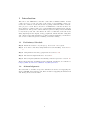
Introduction
Welcome to the ARM microcontroller course 2015 of ETSV Scintilla. In this
course we hope to teach you some of the basics of programming a microcontroller, the common caveats and the fun of getting a mixed hardware and software project to work. We’ve chosen for an ARM microcontroller as these are
more and more common, with a lot of chip manufacturers having their own implementations. The goal is to build a function generator using a Nucleo-F411RE
board, made by ST, and a the shield. In order to build that, we’ll talk about
using digital input and outputs, analog peripherals, timers and SPI. Using that
and a little background information on Direct Digital Synthesis, you should be
able to have a function generator running on the last evening.
1.1
Preliminary Schedule
Day 0 Install the software on your laptop. See section 2 for a guide.
Day 1 C for microcontrollers, using GPIO and event handling. Sections 4 to
8.
Day 2 Using Timers and analog peripherals. Sections 9 to 10.
Day 3 The Serial Peripheral Interface. Section 11.
Day 4 Direct Digital Synthesis and building a function generator. Section 12.
All necessary material, including reference manuals, datasheets, are available at
http://www.scintilla.utwente.nl/docs/cursus.
1.2
Acknowledgments
We would like to thanks our sponsor ST Microelectronics for supplying the
Nucleo-F411RE development board, Eurocircuits for supplying the shield PCB
and Analog Devices for the DAC.
4
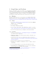
2
Setup Eclipse and Toolchain
In this course Eclipse is used as the IDE, as it’s cross-platform and highly
customizable. It is recommended to use a clean install of Eclipse 4.4 Luna for
C/C++. Besides Eclipse you’ll need to install some Eclipse plugins and drivers
for STLink, the device that connects to your Nucleo board. The guide is written
with Windows and GNU/Linux in mind, but it should work as well on OSX.
2.1
Windows
This guide assumes that you’ve a recent version of Java Runtime Environment
installed. If needed you can download JRE from http://www.oracle.com/
technetwork/java/javase/downloads/jre8-downloads-2133155.html.
2.1.1
Eclipse
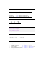
1. Go to http://www.eclipse.org/downloads/ and download Eclipse
IDE for C/C++ Developers
2. Unpack and install.
3. Go to Help → Install New Software
4. click on Add..., fill in Name: GNU ARM Eclipse Plug-ins. Location:
http://gnuarmeclipse.sourceforge.net/updates and press OK
5. select all but the Freescale Project Templates, click Next and install.
2.1.2
Toolchain
1. Get the toolchain from https://launchpad.net/gcc-arm-embedded.
(gcc-arm-none-eabi***-win32.exe)1
2. Install the toolchain, but in the final window disable "Add path to the
environment variable".
3. Download the latest build tools (gnuarmeclipse-build-tools-win32-2.*-*setup.exe) from http://sourceforge.net/projects/gnuarmeclipse/
files/BuildTools/
4. Run the installer, remember the path of the Build Tools.
5. In Eclipse, go to Window → Preferences. C/C++ → Build → Global
Tools Paths
6. Locate the installed Build tools, enter the path in Build Tools folder.
7. Select GNU Tools for ARM Embedded Processors, locate the toolchain and
enter the path in Toolchain folder, and click Apply.
1 On
2/5/2015:
https://launchpad.net/gcc-arm-embedded/
4.9/4.9-2015-q1-update/+download/gcc-arm-none-eabi-4_
9-2015q1-20150306-win32.exe
5
2.1.3
STLink v2
1. Download the latest STLink v2 driver from http://www.st.com/web/
catalog/tools/FM147/SC1887/PF260218
2. Extract files and run stlink_winusb_install
3. Install driver.
4. Download STLink Utility from http://www.st.com/web/en/catalog/
tools/PF258168, install.
2.1.4
Debugger - OpenOCD
This is optional, but a debugger might help you a lot. We’re using OpenOCD
as it’s available for all platforms, and easily integrates with the Eclipse plugins
we installed.
1. Download the latest development (0.9.*) version of OpenOCD for your architecture from http://sourceforge.net/projects/gnuarmeclipse/
files/OpenOCD/Windows/.
2. Follow the installation procedure.
3. In Eclipse go to Window → Preferences → Run/Debug → String Substitutions
4. Fill in the path to the bin directory of OpenOCD in the Value field of
openocd_path, then click OK.
5. The next steps only apply after making a project, see section 3.3.
2.1.5
Packs - Device Support
1. In Eclipse, open the Packs perspective.
2. Click on the Refresh button. It will now load all available packs from Keil.
3. Select the device menu, locate the STM32F4 series and install the package.
2.2
Linux
This guide assumes a working Java runtime environment. It was tested using
OpenJDK 1.8, and should work equally well with a recent version of Oracle
JRE.
2.2.1
Toolchain and Eclipse
1. Get the toolchain from https://launchpad.net/gcc-arm-embedded
(gcc-arm-none-eabi***-linux.tar.bz2)
2. Extract to a directory of your liking.
3. Install Eclipse Luna for C/C++ development, if you haven’t already.2
2 Either via your package manager, or by downloading from http://www.eclipse.org/
downloads/
6
4. open Eclipse, set a workspace and click on Help → Install New software.
5. click on Add..., fill in Name: GNU ARM Eclipse Plug-ins. Location:
http://gnuarmeclipse.sourceforge.net/updates and press OK
6. select all but the Freescale Project Templates, click Next and install.
7. In Eclipse, go to Window → Preferences. C/C++ → Build → Global
Tools Paths
8. Select GNU Tools for ARM Embedded Processors, locate the toolchain
and enter the path in Toolchain folder.
2.2.2
STLink flasher for Linux
The STLink Utility provided by STMicroelectronics is Windows only, but an
open source alternative is available on GitHub.
1. Go to http://github.com/texane/stlink, download the Zip file
2. Extract the zip file to a preferred location.
3. In a terminal cd to the directory the files are in, and build stlink using:
./autogen.sh
./configure
make
sudo make install
4. get the path of st-flash using:
whereis st-flash
5. In Eclipse, click Run → External Tools → External Tools Configurations
6. Click on Program, and then on New. Name the new configuration st-linkv2
flash, and paste the path to st-flash in the Location field.
Working directory: ${project_loc}/Release
Arguments: write ${project_name}.bin 0x8000000
7. Click Apply and close.
2.2.3
Debugger - OpenOCD
This is optional, but a debugger might help you a lot. We’re using OpenOCD
as it’s available for all platforms, and easily integrates with the Eclipse plugins
we installed.
1. Download the latest development (0.9.*) version of OpenOCD for your architecture from http://sourceforge.net/projects/gnuarmeclipse/
files/OpenOCD/GNULinux/.
2. Extract the package to a directory.
3. In Eclipse go to Window → Preferences → Run/Debug → String Substitutions
7
4. Fill in the path to the bin directory of OpenOCD in the Value field of
openocd_path, then click OK.
5. The next steps only apply after making a project, see section 3.3.
2.2.4
Packs - Device Support
1. In Eclipse, open the Packs perspective.
2. Click on the Refresh button. It will now load all available packs from Keil.
3. Select the device menu, locate the STM32F4 series and install the package.
8
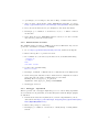
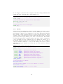
3
Starting a Project
To accompany this guide there is a video walk-through available on https:
//www.youtube.com/watch?v=HxGEBEWRyy8
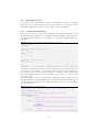
In Eclipse go to File → New C Project. Enter a name for the project,
and select STM32F4xx C/C++ Project from the project type dropdown. From
Toolchains choose the Cross ARM GCC.
In the next menu, for the Nucleo-F411 in the Target processor needs to be
changed to Cortex-M4, the flash size to 512KB, and Content: Empty.
Keep the suggested settings in the Folders menu and Select Configurations menu.
In the Cross GNU ARM Toolchain make sure to select the Toolchain GNU
Tools for ARM Embedded Processors, and if necessary locate the bin
folder of the toolchain. Click Finish. Now a simple project is set up with an
empty main() function.
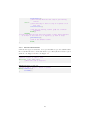
To make optimal use of our Eclipse installation, right-click on the project, and
select Properties. Browse to C/C++ Build → Settings → Devices. Locate
the STM32F411RE, select it and click Okay. You can now test the installation
by pressing the Build icon.
3.1
Clock Configuration
The default clock configuration in the file _initialize_hardware.c, in the src
directory of the project does not work for our Nucleo board. As a start here is
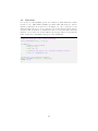
a little bit of code that does. Replace the function configure_system_clock() on
the bottom of the page with the code in snippet 1, which lets the board run on
the external oscillator, with a system frequency of 84MHz.3
3.2
Flashing the Program Memory
To load the binary onto the microcontroller, the STLink Utility can be used, as
well as a debugger.
3.2.1
STLink Utility under Windows
1. Open the STLink Utility
2. Connect to the device by clicking Target → Connect
3. Open the binary projectname.elf and click Burn.
3.2.2
STLink Flash under Linux
1. In Eclipse, go to Project Properties → C/C++ Build → Settings → Build
Steps
2. Add the command to Post-build steps, and give it a description Create
Binary:
arm-none-eabi-objcopy -S -O binary "${ProjName}.elf""${ProjName}.bin
"
3 Try the calculation for yourself using the given formulas in paragraph 6.3.2 of the
datasheet.
9
Snippet 1 84MHz system clock configuration for Nucleo-F411RE
/** System Clock Configuration
*/
void configure_system_clock(void)
{
RCC_OscInitTypeDef RCC_OscInitStruct;
RCC_ClkInitTypeDef RCC_ClkInitStruct;
__PWR_CLK_ENABLE();
__HAL_PWR_VOLTAGESCALING_CONFIG(PWR_REGULATOR_VOLTAGE_SCALE2);
RCC_OscInitStruct.OscillatorType = RCC_OSCILLATORTYPE_HSI;
RCC_OscInitStruct.HSIState = RCC_HSI_ON;
RCC_OscInitStruct.HSICalibrationValue = 16;
RCC_OscInitStruct.PLL.PLLState = RCC_PLL_ON;
RCC_OscInitStruct.PLL.PLLSource = RCC_PLLSOURCE_HSI;
RCC_OscInitStruct.PLL.PLLM = 16;
RCC_OscInitStruct.PLL.PLLN = 336;
RCC_OscInitStruct.PLL.PLLP = RCC_PLLP_DIV4;
RCC_OscInitStruct.PLL.PLLQ = 4;
HAL_RCC_OscConfig(&RCC_OscInitStruct);
RCC_ClkInitStruct.ClockType = RCC_CLOCKTYPE_SYSCLK|
RCC_CLOCKTYPE_PCLK1;
RCC_ClkInitStruct.SYSCLKSource = RCC_SYSCLKSOURCE_PLLCLK;
RCC_ClkInitStruct.AHBCLKDivider = RCC_SYSCLK_DIV1;
RCC_ClkInitStruct.APB1CLKDivider = RCC_HCLK_DIV2;
RCC_ClkInitStruct.APB2CLKDivider = RCC_HCLK_DIV1;
HAL_RCC_ClockConfig(&RCC_ClkInitStruct, FLASH_LATENCY_2);
}
10
3. Now you can run st-flash by clicking Run → External Tools → stlinkv2
3.3
Debugging
This part assumes you installed OpenOCD, as in section 2.1.4 for Windows or
2.2.3 for GNU/Linux.
1. Build the project and make sure the executable file exist.
2. Go to Run → Debug Configurations...
3. Select the GDB OpenOCD Debugging group and click New.
4. In the new configuration, the Main tab should already be filled in. Click
on the Debugger tab.
5. Add the following line to the Config Options
-f board/st_nucleo_f4.cfg
6. Click on the Common tab, and select Shared file
7. Click Apply and Close.
11
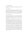
4
Programming C
Due to its low level description, C is a relatively simple language to get started
with: it features only a minimum of possible operations, so there is not that
much to learn.
4.1
Data Types
Every operation needs at least one variable. There are two types of variables:
integer type variables (for integer numbers) and floating point variables (for
non-integer numbers). In ARM microcontrollers it is strongly advised to use
unsigned integer type variable with a size of 32 bits or less standard. Longer
data types or floating point variables take more time to perform operations on
and thus decrease performance and increase power consumption. Keep in mind
that an ARM has 32 bit registers: using data types smaller than this will not
save memory, but will just leave the rest of the bits in the register unused.
4.1.1
Integer Data types
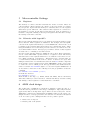
The integer type variables can be found in table 1. This table shows that there
is no Boolean type variable. To be able to process operations which require a
true/false input, any other integer data type can be used. Giving the value “0”
as the argument of a function will execute the same as a logic “false” and any
other value will be processed as a logic “true”. The code snippet in Snippet 2
will thus switch on an LED. The LED will switch on for every value of x, as
long as it not 0.
In microcontrollers it is very common to use an integer as an array of bits.
For example a 16 bits unsigned integer (uint16_t) can not only be used to store
a 16 bit number, but could also be used to store 16 bits. For this we have to
know how unsigned integers are stored. This type of integers is stored as a
binary number. If we consider the decimal number “1234”, this can be stored in
binary as “0b0000010011010010”. The “0b” is a marking which determines that
a number is given in binary and the zeros at the beginning are added to show
this is a 16 bit number. Microcontrollers often have setting registers where one
bit e.g. determines if a hardware peripheral is switched on. To alter this specific
bit one can use bitwise operators, which will be discussed later in this manual.
Apart from the binary “0b” notation, hexadecimal notation is very common
as well. Instead of base 10 (decimal) or base 2 (binary) we now use base 16.
This notation can be considered to be a short form of binary notation which
groups four bits in one digit. The star of a hexadecimal number is indicated
with “0x”. In hexadecimal notation one can now count 0, 1, 2, 3, 4, 5, 6, 7, 8,
9, A, B, C, D, E, F. In this base 16, 0x0 is the same as 0b0000, 0x5 is the same
as 0b0101 and 0xE is the same as 0b1110. The longer decimal number 1234
can be converted to hexadecimal by separating the binary number in groups of
four digits and rewriting these groups to hexadecimal. “0b0000 0100 1101 0010”
in hexadecimal notation will become “0x04D2”. Hexadecimal numbers have the
advantages of both binary and decimal notation: it is grouped per bit, but the
notation is still short.
12
Snippet 2 Example of an integer as a Boolean
uint16_t x = 1615;
if(x){
setLED();
}else{
resetLED();
}
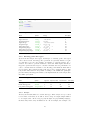
Table 1 Integer data types in C
Name
Syntax
Range
Size (bits)
Boolean
Signed character
Unsigned character
Signed integer
Unsigned integer
Signed long integer
Unsigned long integer
Signed long long integer
Unsigned long long integer
Non-existent
int8_t
uint8_t
int16_t
uint16_t
int32_t
uint32_t
int64_t
uint64_t
There are no Booleans in standard C
−128 to 127
0 to 255
−32, 768 to 32, 767
0 to 65, 535
−231 to 231 − 1
0 to 232 − 1
−263 to 263 − 1
0 to 264 − 1
1
8
8
16
16
32
32
64
64
4.1.2
Floating point data types
Apart from the integer data types, non-integer or “floating point” data types
can be used as well. Floating point operations are generally harder for a microcontroller to process. For example, it is harder to perform 1.23456 · 101 +
9.87654 · 10−2 than to perform 12345678 + 98765432. This implies that floating point operations take longer to calculate and thus decrease performance. It
can be concluded that it is unwise to use floating point numbers when this is
not necessary. The possible floating point types can be found in Table 2. The
long double indicated here is specified according to the “IEEE 754 quadrupleprecision binary floating-point format”, but implementations of the long double
may differ per system.
Table 2 Floating point data types in C
Name
Syntax
Sign bit
Exponent bits
Fraction bits
Size (bits)
Floating point
Double floating point
Long double floating point
float
double
long double
1
1
1
8
11
15
23
52
112
32
64
128
4.1.3
Arrays
An array is an indexed lists of a certain data type. These arrays can e.g. be used
to store lists of variables, as we will do later to map an output sample number
to an output value. As in every properly thought out programming language,
the first entry in the array is numbered “0”. As an example, the example code
13
in code snippet 3 generates a list of squares of the first 8 integer numbers and
returns the value of the fifth square. This should be 25.
Snippet 3 Example code for reading and writing of an array
//generate a list of 8 signed numbers of 16 bits named "y"
uint16_t y[8];
//fill the list with the squares of the index numbers
for(uint16_t i=0; i<8; i++){
y[i] = i*i;
}
//return the value of the fifth square
return y[5];
4.1.4
Structs
C is no object oriented language, but has a feature which comes close to object
oriented storing of variables. This can be done by defining a so called “struct”
type variable. A struct can be considered to be an object with several variables
in it. Structs are used often where there is a clear repetition in data sets. As an
example, a microcontroller has several sets of input and output pins (or “general
purpose input and output (GPIO) ports”, more about this later). Each GPIO
port has (amongst others) a setting for pin modes. Data could be organized in
a very convenient way if we could make an object “GPIO port” with as one of
its internal variables a value for the pin mode for that port. In code snippet
4 the type definition (similar to a class) for the GPIO ports is given, a struct
(similar to an object) “GPIOA” is created, and one of its variables is changed
and returned.
Snippet 4 Example of defining and working with a struct
//give a type definition for the GPIO structs
typedef struct
{
uint32_t MODER;
//GPIO port mode register
uint32_t OTYPER;
//GPIO port output type register
uint32_t OSPEEDR; //GPIO port output speed register
uint32_t PUPDR;
//GPIO port pull-up/pull-down register
uint32_t IDR;
//GPIO port input data register
uint32_t ODR;
//GPIO port output data register
uint32_t BSRR;
//GPIO port bit set/reset register
uint32_t LCKR;
//GPIO port configuration lock register
uint32_t AFR[2];
//GPIO alternate function registers
} GPIO_TypeDef;
//initialize GPIO port "GPIOA"
GPIO_TypeDef GPIOA;
//Set the variable "MODER" in the struct "GPIOA" to "0x0001"
GPIOA->MODER = 0x0001;
//return the variable "MODER" of struct "GPIOA"
return GPIOA->MODER;
14
4.1.5
Enumerated type
An enumerated type is a limited list of keywords, using symbolic names to make
a program clearer to the programmer. This data type will be useful when you
want to implement a state machine, as in code snippet 5. The defined keywords
can be used directly in code.
Snippet 5 Example of a state machine using enumerated type
//define the enumerated type States with three possible values
typedef enum
{
startState,
waitState,
processState
} States;
//declare and initialize mystate to startState.
States mystate = startState;
4.2
Operators
To perform operations on variables, operators can be used. These operators can
be categorized into 4 main categories:
1. Mathematical (arithmetic) operators
2. Comparison operators
3. Logical operators
4. Bitwise operators
This section gives a brief overview of these operators.
4.2.1
Standard Operators
A list of standard mathematical operators in C can be found at: http://en.
wikipedia.org/wiki/Operators_in_C_and_C%2B%2B#Arithmetic_operators
A list of standard comparison operators can be found at: http://en.wikipedia.
org/wiki/Operators_in_C_and_C%2B%2B#Comparison_operators.2Frelational_
operators
4.2.2
Logical Operators
Logical operator do operations on word. This means That a variable is processed
as a logical “false” if its value is 0 and is processed as a logical “true” if it has
any other value. A list of the possible logical operators is given in Table 3.
Table 4 shows how the operation 0b1100 && 0b0110 is performed.
These operators base their input on a whole word. There are also operations
which perform logical operations based in each individual bit in a word. These
are called bitwise operators
15
Table 3 List of logical operators on words
Name
Syntax
Application
Logical NOT
Logical OR
Logical AND
!a
a || b
a && b
Returns the logical inverse of a
Returns “true” if a, b or both are true
Returns “true” if a and b are both true
Table 4 Processing of a logical operation on a word
a
b
1
0
4.2.3
1
1
0
1
0
0
→
→
TRUE
TRUE
return value:
TRUE
&&
Bitwise operators
A bitwise operator performs the logical operation not per word, but per bit. A
list of possible bitwise operators is given in table 5
Table 6 shows how the operation 0b1100 & 0b0110 is performed. This shows
that the logical and operation is performed for every column and not for the
whole word. This will later prove very useful for reading, setting and clearing
specific bits.
4.2.4
Compound assignment operators
It is very common to perform bitwise operation where a certain variable is
both one of the arguments, as well as the location to store the result of the
operation. For this a shortened form called a “compound assignment operator” can be used. This allows to for shorter code over which the programmer has a better overview. For example the logical operations in code snippet 6 perform exactly the same operation. A full list of these operators can
be found at http://en.wikipedia.org/wiki/Operators_in_C_and_
C%2B%2B#Compound_assignment_operators
Snippet 6 Example of compound statements
//initializing the variables
uint8_t x = 0b01010101;
uint8_t y = 0b00001111;
//performing a bitwise operation on variable x
x = x & y;
//performing the same operation again using a compound assignment
operator
X &= y;
An example which uses a lot of these bitwise operators is the resetting of a
specific bit. It might sound simple to set a single “1” to a “0”, but takes quite
some steps to clear bit 5 as is Table 7. To perform this operation, the code in
code snippet 7 is used. This code is explained step by step in table 8.
16
Table 5 List of bitwise operators
Name
Bitwise
Bitwise
Bitwise
Bitwise
Bitwise
Bitwise
NOT
OR
AND
exclusive OR
left shift
right shift
Syntax
Application
~a
a | b
a & b
a ^ b
a << b
a >> b
Flips all bits in a
ORs the first bit of a with the first bit of b, etc.
ANDs the first bit of a with the first bit of b, etc.
XORs the first bit of a with the first bit of b, etc.
Shifts the bits in a b places to the left
Shifts the bits in a b places to the right
Table 6 Processing of a bitwise operator
a
b
1
0
1
1
0
1
0
0
return value:
0
1
0
0
&
Snippet 7 Example of the clearing of a single bit in a register
//initializing the variables
uint8_t x = 0b10101010;
uint8_t bitToClear = 5;
//clearing the bit to clear
x &= ~(1<<bitToClear);
Table 7 Example of clearing of a single bit
Bit number
7
6
5
4
3
2
1
0
Current value of x
Desired value of x
1
1
0
0
1
0
0
0
1
1
0
0
1
1
0
0
Table 8 Step by step explanation of the code in snippet 7
#
Description
Substituted code
1
2
3
4
5
6
7
Original statement
Rewriting &= to the full form
Substituting x and bitToClear
Rewriting 1 to binary
Performing the bitshift between brackets
Performing the bitwise NOT operation
Performing the AND operation
x
x
x
x
x
x
x
17
&= ~(1 << bitToClear);
= x & ~(1 << bitToClear);
= 0b10101010 & ~(1 << 5);
= 0b10101010 & ~(0b00000001 << 5);
= 0b10101010 & ~(0b00100000);
= 0b10101010 & 0b11011111;
= 0b10001010;
4.3
Statements in C
To build logical blocks with these operators, statements are added to determine
when and how to perform the logical operations. This can be done using control
statements. This section will cover some basic control statements.
4.3.1
Conditional Statements
There are two types of conditional statements: if statements and switch cases.
In this manual we assume you are familiar with if statements. The syntax for
a C if statement is as given in code snippet 8, both with or without the “else”
statement.
Snippet 8 Example of an if statement with and without an else clause
int16_t x = -3;
int16_t y;
//set y as the absolute value of x
if(x > 0){
y = x;
}else{
y = -x;
}
//set x to its absolute value
if(x < 0){
x = -x;
}
Alternative to the if statement, a switch statement can be used. The given
argument determines to which line in the statement the program will jump. In
code snippet 9 an example of a morning routine is given. If you wake up on
time, there is time to take a shower and have breakfast, if there is little time
left, you will skip some steps and if your wake up very early or too late you will
go back to sleep.
The same routine could be realized using if statements, but in many cases the
switch statement is more insightful and convenient. Switch statements are extremely useful to implement state machines and execute some code depending
on a state variable.
Snippet 9 Example of a switch statement
//variable for time until your lecture starts in quarters of an hour
int16_t timeToLecture = 2;
//choose what to skip depending on how much time you have
switch(timeToLecture){
case 4:
//just do the same routine as when you had 3 quarters
of an hour
case 3:
//if you have 3 quarters of an hour start by taking a
shower
takeAShower();
//then continue with the next step of your morning
routine
case 2:
//if you have 2 quarters of an hour have some breakfast
18
haveBreakfast();
//then continue with the next step of your morning
routine
case 1:
//leave directly if there is only on 1 quarter of an
hour left
leaveForLecture();
//and end your morning routine (jump out of switch
statement)
break();
default:
//in the case that the time until the lecture is more than 4 quarters
of an hour or less than 1 (0 or negative), go back to sleep.
goBackToSleep();
//end of the default routine
break;
}
4.3.2
Iteration Statements
C knows two types of iterations: for loops and while loops. It is assumed that
the reader knows how to work with these loops. The syntax for these loops is
given in code snippet 10 and code snippet 11.
Snippet 10 Example of a for loop
//perform a piece of code 10 times
for(uint16_t i=0; i<10; i++){
//write the code to loop here
}
Snippet 11 Example of a while loop
//blink an LED as long as a button is pushed
while(readButton()){
blinkLED();
}
19
4.4
Functions
If code is to be used multiple places, it is advised to make functions of these
blocks of code. This manual assumes you know what functions are. The C
syntax for functions is as given in code snippet 12. Use a reference to the
function inside the main() scope and the code in the function block will be
executed. The declaration of a function needs to be before the first call of the
function. To do that you can use function prototypes, where you specify the
name, return type and number and types of the arguments.
Snippet 12 Example of a function
//function prototype of the function multiply
int16_t multiply(int16_t, int16_t);
int main(){
//define some variables
int16_t a = 4;
int16_t b = 5;
//calculate the value for c using the multiply function
int16_t c = multiply(a, b);
}
//definition of the function multiply
int16_t multiply (int16_t x, int16_t y){
return x * y;
}
20
5
Microcontroller Settings
5.1
Registers
The memory of a microcontroller is divided into words of 32 bits. These are
called “registers”. These registers can contain e.g. the stored value of a variable
in your process. Apart from the memory for variables, there are also registers
which have special functions. The values in these registers are connected to
in hardware to specific blocks with specific functions, such as settings for a
hardware component. Writing to those special registers allow the user to change
the settings of the microcontroller.
5.2
Libraries with “typedef ”s
The special registers mentioned above are physical places in the memory of the
microcontroller. These registers are numbered. For example, the least significant bit in the register with memory location 0x40023830 controls if the clock
to GPIO port A is enabled (this register will soon be explained in detail). These
hexagonal numbers are not the most practical reference, as it will soon be unclear which number means. In larger projects where dozens of these registers
are used it is too confusing to use this notation.
For more clarity, libraries with type definitions can be used. These tables function as a table which links a practical name to a register location. The library
with this table for the registers which have to do with the “reset and clock control” (RCC) settings is "stm32f4xx.h". This library sets a variable name for
a certain memory address in the form of a struct. A struct is an object with
multiple variables in it. For the RCC the struct is called RCC and the component
needed enable clocks to GPIO ports is called “AHB1ENR”. In the case we want
to enable the clock to GPIO port A the typedef library has defined that the
value for variable RCC->AHB1ENR ought to be stored in register 0x40023830. If
we now want to enable the clock to GPIO port A, the programmer can use the
command
RCC->AHB1ENR = RCC->AHB1ENR | 0x0001;
Or in shorter notation:
RCC->AHB1ENR |= 0x0001;
Each module of the chip, e.g. GPIO, timers and ADCs, has its own library
with those memory location references. Include this library and the reading
and writing to these registers becomes much more convenient.
6
ARM clock design
The architecture of ARM microcontrollers is designed to make the user do a
tradeoff between performance and energy consumption. Especially in mobile
applications, this is an important aspect which can save battery life. As the
ARM microcontrollers are implemented in CMOS technology, the energy consumption is more or less proportional to the amount of clock ticks of the system
clock. To reduce power consumption there are two possible options:
1. Reduce the clock speed
2. Disable parts of the system
21
Both these options can be configured in the system settings of an ARM. After a
reset or power down, the ARM reboots and sets a 16MHz internal RC oscillator
as system clock and disables all hardware peripherals. This means that to use
any subsystem of the chip, e.g. GPIO pins, DACs and timers, the clock to this
module has to be enabled first.
If clock frequencies higher than 16MHz are required (which it will be near the
end of the course), the internal phase locked loop (PLL) has to be used. This
PLL uses the 16MHz RC oscillator as an input and multiplies this frequency to
generate a high frequency clock. If this PLL output is then set to function as
the system clock, higher performance can achieved at the cost of a higher power
consumption.
7
GPIO
GPIO is an abbreviation for “General Purpose Input and Output” and allows
the programmer to read or set the voltages on the pins of the microcontroller
to a high (3.3V) or low (0V) value. In ARM microcontrollers, the input and
output pins can be read and written to similar to a memory address. Input
pins are connected to a (read only) input data register which can be read in the
same way any other register is read. Output pins are connected to an output
data register. This is a register just like any other, except this memory cell
is connected to pins, so the bits in this register determine the voltages on the
pins of the chip. This principle of interacting with GPIO pins in the same
way as with memory addresses is called “memory mapped input and output” or
“memory mapped IO”.
The GPIO pins are grouped in functional units called ports. The microcontroller
used for this course features six ports: port A, B, C, D, E and F. Each port
has multiple registers to change the settings for the pins in it. The rest of this
chapter will use a small x to indicate a register, this x can be replaced by the
letters A, B, C, D, E and F to function for this specific port. E.g. the mode
register (GPIOx_MODER) for port B is “GPIOB_MODER”. The registers
with the possible settings for GPIO pins are given in table 11.
Exercise 1
Turn on the LED on the Nucleo board. To do this follow the following steps:
1. Find out to which microcontroller pin the user LED is connected (refer to
chapter 5.4 and table 15 of the Nucleo user manual)
2. Enable the clock to this pin.
3. Initialize this pin
4. Switch on the LED
8
Polling and Interrupts
There are three ways of writing a microcontroller program. The first way is write
a program which executes all lines of code from top to bottom and then finishes,
22
Table 9 List of possible GPIO settings in ARM microcontrollers
Register
CH.
Full name
Function
GPIOx_MODER
8.4.1
Mode register
Sets a pin as input or output pin
GPIOx_OTYPER
8.4.2
Output type
register
Sets an output pin as push pull
or open drain mode
GPIOx_OSPEEDR
8.4.3
Output speed
register
Sets the maximum speed of an
output pin to 2MHz, 10MHz or
50MHz
GPIOx_PUPDR
8.4.4
Pull-up/pull-down
register
Allows to add a pull-up or
pull-down register
GPIOx_IDR
8.4.5
Input data register
Allows to read the digital value
of an input pin
GPIOx_ODR
8.4.6
Output data
register
Sets the digital value to output
to a pin
GPIOx_BSRR
8.4.7
Bit set/reset
register
Allows to set or clear a bit in the
output data register in one step.
GPIOx_LCKR
8.4.8
Lock register
Allows locking of the settings
above
GPIOx_AFRL GPIOx_AFRH
8.4.9
8.4.10
Alternate function
register (64-bits
long)
Allows to set alternative
functions for a pin
similar to e.g. a MATLAB calculation. This is what you have done in exercise
1. In virtually all practical cases a microcontroller executes a continuous task
and is never finished with its program. This leaves us the other two options.
8.1
Polling
A way to program a microcontroller program to run until the end of times is
with the use of a while(1){} loop. As the argument for the loop will be true
forever, the microcontroller will loop the code within the braces forever. Your
code can now be split up in two parts: first an initialization to be performed
once, followed by a loop with the code which should be run continuously. An
example project which turns on an LED when a button is pressed could be
as in code example 13. Keep in mind that this example refers to a library
(buttonLED.h) to call functions from, so this example code alone is not enough
to switch the LED on and off. This approach, the microcontroller will check the
state of the button every time the loop is performed. Processes in which the
processor checks for input, such as the LED example in code example 13 are
called “polling”. Polling is easy to implement and gives programmer complete
control over the order of the performed instructions, but it does have some
downsides.
23
Snippet 13 Example of using a while(1) loop and polling
//include a libraries here
#include buttonLED.h
int main(){
//run the initialization code here
initPins();
while(1){
//the code to loop continuously goes here
//check if the button is pushed
if(readButton()){
//switch on LED if the button is pushed
setLED();
}else{
//switch off LED if button is not pushed
resetLED();
}
}
}
Exercise 2
Switch on the LED when the user button is pushed. To do this follow the
following steps:
1. Find out to which microcontroller pin the user button is connected (refer
to chapter 5.5 of the Nucleo user manual)
2. Enable the clock to this pin and the LED pin.
3. Initialize these pins
4. Read the button input (the electrical connection of the button to the
microcontroller can be found in figure 25 of the Nucleo user manual).
5. Switch on the LED when the button is pushed using polling.
Exercise 3
A problem occurring often is that buttons physically bounce when pushed. The
effect of this is that instead of switching on neatly, the button input might flicker
a few times before staying on. You can compensate for this by letting your code
check if the button input is stable over a longer period. Toggle the LED state
when you press the user button: switch the LED on when the user button is
pushed and off when it is pushed again. If the button seems to “fail” sometimes
when you press it, you are experiencing bouncing.
8.2
Interrupts
Alternative to polling, event based interrupts can be used. In this way of designing a process, the processor does not check for input, but a set event will trigger
the processor to jump to a certain part of your code. In the case of the switching
24
of the LED it would be more convenient if we could write a program which executes the function setLED() when the button input becomes high, and performs
the function resetLED() when the button input becomes low. This means we
only have to execute code when the button input changes. In your code you can
program at which events you want the microcontroller to generate an interrupt
and how to handle this when this happens. Some examples of things which can
generate interrupts are changing levels on input pins (pin change interrupts),
periodic interrupts (timer interrupts) or input on communication busses (e.g.
SPI interrupts).
To enable an interrupt for a specific function, you first have to enable the Nested
Vector Interrupt Controller (NVIC), for the specific interrupt vector. After an
event occurs for which you enabled the interrupt, the program pointer automatically switches to a callback function, called the interrupt service routine (ISR)
or interrupt handler. In this function you must clear the interrupt flag. An
example for enabling an interrupt and an interrupt handler is given in snippet
14. All interrupt registers can be found in chapter 10 of the reference manual.
Snippet 14 Example of enabling an interrupt and ISR
// for button at PC0
// EXTI0, bit 2 (SYSCFG->EXTICR[0], bit 2)
NVIC_EnableIRQ(EXTI0_IRQn); // enable IRQ for ext signals on EXTI0_IRQn
NVIC_SetPriority(EXTI0_IRQn, 13); // set the priority
SYSCFG->EXTICR[0] = SYSCFG_EXTICR1_EXTI0_PC;
EXTI->RTSR |= 0x00000001;
// set EXTI line 0 (EXTI0) to rising
trigger enabled
EXTI->IMR |= 0x00000001;
// enable interrupt for EXTI0
// the ISR:
void EXTI0_IRQHandler(void)
{
if(EXTI->PR & 1) {
// do some fancy stuff
}
EXTI->PR |= 1; //clear interrupt flag of EXTI0 by writing a 1.
}
Exercise 4
In exercise 3 polling was used to read out the button. A good exercise before
going on to timers would be to try it with an interrupt. Enable the interrupt
for the user button, then write an interrupt service routine in which you toggle
the LED.
8.3
Polling vs. Interrupts
Polling and interrupts both have their advantages and disadvantages, but in the
general case polling is easier and interrupts are faster and more efficient.
25
Table 10 Comparison of polling and interrupts
Principle
Implementation
Polling
Interrupts
Let the processor check if inputs have
changed
A while(1){} loop (very easy)
Execute code immediately at
an event
Event triggers and event
handlers (less simple)
Interrupts can cause delays
at unwanted moments,
causing errors.
Immediately
The processor only executes
code when an event takes
place.
Processor can run slower
when there is no event,
saving power.
Robustness
Code is always executed in the same
order without interruption
Reaction time
Processor time costs
Every time the loop is executed
The processor wastes clock ticks on
checking variables which are the same
most of the time.
Processor always runs at 100% : energy
consumption is always maximum.
Power consumption
26
9
Timers
A peripheral found in all microcontrollers is the timer. Timers is a counter fed
by a clock. It can be considered to be a register which increments or decrements
(depending on the timer settings) by one on every tick of a clock connected to
it.
The microcontroller on the Nucleo has seven general purpose timers: TIM2
-TIM5 and TIM9 - TIM11 of which the latter only count upwards. The timers
can be fed with different clock sources, internally or externally. This clock
source is fed through a programmable 16-bit clock divider called "prescaler" to
generate a clock signal for the timer. If the counter TIMx_CNT reaches a so
called auto-reload value TIMx_ARR it resets the counter to zero and throws a
event.
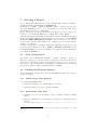
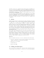
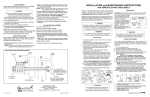
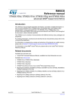
The counter is connected to four input capture/ output compare channels
TIMx_OC. These channels can be connected to a output pin and can work in
different modes ranging from measuring the pulse length on a input to toggle a
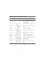
output. In figure 1 a simplified sketch is made to give insight in the purpose of
the auto-reload and the output compare registers. Of course is this only one of
the possible modes of operation. Look in the reference manual in chapter 13 or
14 for more in depth information about which registers to use.
There are also timers with more specific task: The main purpose of a watchdog is to check whether or not the code not hangs, it does this by being set
periodically to an initial value, if for some reason this does not happen, then
the device gets reset or an event is thrown.
Another timer is the Systick timer. This timer runs on the background and is
used to generate so called ticks which are used by a realtime operating system
to schedule slots for the different task.
Exercise 5
Use a Timer 2 to make an LED blink. To do this follow the following steps
1. Set up the the LED as output.
2. Enable the clock to timer 2.
3. Initialize the timer using a TIM_HandleTypeDef from the HAL.
4. Set up the timer interrupt NVIC priority and enable this interrupt using
the HAL.
5. Start the timer using the HAL.
6. Make an interrupt routine for TIM2_IRQHandler to call to HAL_TIM_IRQHandler
7. Make the LED blink on the "period elapsed" routine (HAL_TIM_PeriodElapsedCallback).
27
Table 11 List of possible GPIO settings in ARM microcontrollers
Register
CH.
Full name
Function
TIMx_CR1
13.4.1 Control register one
Main control register, used for enabling the
counter and setting the counter mode
TIMx_CR2
13.4.2 Control register two
Second control register, used for setting DMA
and other triggering
TIMx_SMCR
13.4.3 Slave mode control
register
Settings used for using the timer in slave mode
TIMx_DIER
13.4.4 DMA / interupt
enable register
Used for enabling the different interupt/ dma
events
TIMx_SR
13.4.5 Status register
Houses all the interrupt flags
TIMx_EGR
13.4.6 Event generation
register
Settings for generating DMA events
TIMx_CCMR1
13.4.7 Capture/ Compare
mode register 1
Mode selection of the different channels
TIMx_CCER
13.4.9 Capture/ Compare
enable register
Setting for the polarity of the channels and
enabling them
TIMx_CNT
13.4.10Counter register
The register containing the counter value
TIMx_PSC
13.4.11Prescaler register
Prescaler used for dividing the clock
TIMx_ARR
13.4.12Auto-reload register
The register containing the auto-reload value
TIMx_CCR1
13.4.13Capture/ Compare
register channel 1
The register containing the capture/ compare
value of channel one
TIMx_DCR
13.4.17DMA control register
Settings for the DMA
TIMx_DMAR
13.4.18DMA adress register
for full transfer
The register containing the adress for burst
DMA
TIM2_OR
13.4.19TIM2 option register
Extra options
28
Figure 1: Simplified timing diagram
29
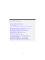
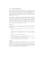
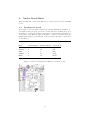
10
Analog Peripherals
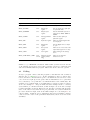
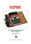
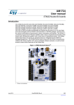
Like most microcontrollers, the used STM32F411 microcontroller has an internal analog to digital converter (ADC). There are 19 input channels to select:
16 GPIO channels, an internal reference voltage, an internal temperature sensor and a battery voltage monitoring feature, connected via an internal voltage
divider. To function properly, the ADC requires a proper ADCCLK clock,
from the ADC prescaler. An overview of this can be seen in figure 2, from the
STM32F411 reference manual.
The ADC can be started from various triggers, both internal and external,
and can generate interrupts when done. It also supports several modes: single
conversion mode, free running mode (convert a single channel continuously),
and group conversion (convert a group of channels in sequence, in arbitrary
order). When reading the reference manual, the difference between injected and
regular channels can be a bit unclear, so for clarity: the injected channels can
have a higher priority than the regular ones, making it possible to interrupt a
regular conversion group for an injected conversion.
Exercise 6
Use the ADC to read the output voltage of the potentiometer on the custom
shield and use it to alter the LED blinking frequency. To do this, follow the
following steps:
1. Find the right ADCCLK frequency from the datasheet, and set (and enable it).
2. Find, from the reference manual, what has to be done to use the ADC.
3. Set the ADC to continuously running mode, on the channel for the right
IO pin.
4. Find out what bit is set when the ADC is done.
5. Implement polling for this bit in your main loop from the timer example.
Set the blinking frequency for the LED when required.
6. Replace the polling routine by an interrupt for faster code, by enabling
the ADC interrupt. (Or continue to the next exercise).
Exercise 7
Polling the ADC to check whether it has finished yet cost processor clock ticks,
and results in a false answer most of the time. It thus is a waste of processor
resources to do this using polling. A more elegant and processor efficient approach to execute a routine when the ADC has finished would be by having the
ADC generate an interrupt when it has finished. To do this, replace the polling
routine by an interrupt by enabling the ADC interrupt.
30
Figure 2: ADC block diagram
31
11
SPI
12
Project: build a Function Generator
13
Energy Consumption
32
A
Nucleo Board Hints
This appendix will contain some hints we’ve collected for the Nucleo F411RE
board.
A.1
Breaking the board
It’s possible to use the Nucleo without the attached STLink programmer. So
you might as well put some action in your life and start breaking the board.
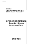
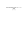
You’ll have to connect an external power supply, as explained in paragraph 5.3.2
of the Nucleo User Manual. Then you’ll have to connect a few wires from the
STLink CN4 connector to the Morpho connector CN7 of the Nucleo, check table
12 and figure 3.
Table 12 STLink connections for a cut Nucleo board.
Name
STLink CN4 pin
Morpho CN7 pin
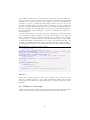
Colour (fig 3)
VDD Target
SWCLK
GND
SWDIO
NRST
1
2
3
4
5
12
15
8
13
14
Purple
Red
Blue
Green
Brown
Figure 3: Connection diagram for STLink to cut Nucleo board.
33
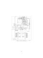
B
Function Generator Shield
In table 13 the connections of the Shield components to the Arduino header
and STM32F411RE microcontroller can be found. LEDx are the LEDs, BUTx
the three buttons, POT is the analog input of the potentiometer and CS, MOSI
and SCK are connected to the DAC. Although you can use the capacitive touch
buttons, P1 to P4, on the shield, it requires some additional programming.
Table 13 Pin connections of the shield to the Arduino header and STM32F411RE microcontroller.
Component
Arduino Pin
STM32 Pin
Alternate function
LED0
LED1
LED2
BUT0
BUT1
BUT2
CS
MOSI
SCK
POT
D3
D5
D6
D7
D8
D9
D10
D11
D13
AD4
PB3
PB4
PB10
PA8
PA9
PC7
PB8
PA7
PA5
PC1
SPI1_CS
SPI1_MOSI
SPI1_SCK
ADC1_11
P1
P2
P3
P4
AD3
AD2
AD1
AD0
PB0
PA4
PA1
PA0
ADC1_8
ADC1_4
ADC1_1
ADC1_0
34
List of Tables
1
2
3
4
5
6
7
8
9
10
11
12
13
Integer data types in C . . . . . . . . . . . . . . . . . . . . . . . 13
Floating point data types in C . . . . . . . . . . . . . . . . . . . 13
List of logical operators on words . . . . . . . . . . . . . . . . . . 16
Processing of a logical operation on a word . . . . . . . . . . . . 16
List of bitwise operators . . . . . . . . . . . . . . . . . . . . . . . 17
Processing of a bitwise operator . . . . . . . . . . . . . . . . . . . 17
Example of clearing of a single bit . . . . . . . . . . . . . . . . . 17
Step by step explanation of the code in snippet 7 . . . . . . . . . 17
List of possible GPIO settings in ARM microcontrollers . . . . . 23
Comparison of polling and interrupts . . . . . . . . . . . . . . . . 26
List of possible GPIO settings in ARM microcontrollers . . . . . 28
STLink connections for a cut Nucleo board. . . . . . . . . . . . . 33
Pin connections of the shield to the Arduino header and STM32F411RE
microcontroller. . . . . . . . . . . . . . . . . . . . . . . . . . . . . 34
Code Snippets
1
2
3
4
5
6
7
8
9
10
11
12
13
14
84MHz system clock configuration for Nucleo-F411RE . . .
Example of an integer as a Boolean . . . . . . . . . . . . . .
Example code for reading and writing of an array . . . . . .
Example of defining and working with a struct . . . . . . .
Example of a state machine using enumerated type . . . . .
Example of compound statements . . . . . . . . . . . . . . .
Example of the clearing of a single bit in a register . . . . .
Example of an if statement with and without an else clause
Example of a switch statement . . . . . . . . . . . . . . . .
Example of a for loop . . . . . . . . . . . . . . . . . . . . .
Example of a while loop . . . . . . . . . . . . . . . . . . . .
Example of a function . . . . . . . . . . . . . . . . . . . . .
Example of using a while(1) loop and polling . . . . . . . .
Example of enabling an interrupt and ISR . . . . . . . . . .
35
.
.
.
.
.
.
.
.
.
.
.
.
.
.
.
.
.
.
.
.
.
.
.
.
.
.
.
.
.
.
.
.
.
.
.
.
.
.
.
.
.
.
10
13
14
14
15
16
17
18
18
19
19
20
24
25