1
GPS 15xH/15xL
TECHNICAL
SPECIFICATIONS
190-00266-03 Revision A
December 2009
© Copyright 2009
Garmin Ltd. or its subsidiaries
All Rights Reserved
Except as expressly provided below, no part of this manual may be reproduced, copied, transmitted,
disseminated, downloaded, or stored in any storage medium, for any purpose without the express
prior written consent of Garmin. Garmin hereby grants permission to download a single copy of this
manual and of any revision to this manual onto a hard drive or other electronic storage medium to be
viewed and to print one copy of this manual or of any revision hereto, provided that such electronic or
printed copy of this manual or revision must contain the complete text of this copyright notice and
provided further that any unauthorized commercial distribution of this manual or any revision hereto
is strictly prohibited.
Information in this document is subject to change without notice. Garmin reserves the right to change
or improve its products and to make changes in the content without obligation to notify any person or
organization of such changes or improvements.
Garmin International, Inc.
1200 East 151st Street
Olathe, KS 66062 U.S.A.
Telephone: 913/397.8200
FAX: 913/397.8282
Garmin (Europe) Ltd.,
Liberty House, Hounsdown Business Park,
Southampton, Hampshire, SO40 9LR UK
Tel. +44 (0) 870.8501241 (outside the UK)
0808 2380000 (within the UK)
Fax +44 (0) 870.8501251
Garmin Corporation
No. 68, Jangshu 2nd Road
Sijhih, Taipei County, Taiwan
Telephone: 886/2.2642.9199
FAX: 886/2.2642.9099
www.garmin.com
GPS 15xH/15xL Technical Specifications
Page ii
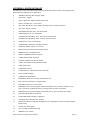
TABLE OF CONTENTS
1
Introduction..................................................................................................................1
1.1 Caution ..............................................................................................................................................1
1.2 Limited Warranty ..............................................................................................................................2
1.3 Overview...........................................................................................................................................3
1.4 Features .............................................................................................................................................3
1.5 Technical Specifications ...................................................................................................................3
1.5.1
1.5.2
1.5.3
1.5.4
1.5.5
1.5.6
2
Physical Characteristics ......................................................................................................................... 3
Electrical Characteristics........................................................................................................................ 4
Environmental Characteristics ............................................................................................................... 4
GPS Performance................................................................................................................................... 4
Interfaces................................................................................................................................................ 4
Antenna Specifications .......................................................................................................................... 5
GPS 15xH/15xL Wire Descriptions and Wiring Diagrams......................................6
2.1 GPS 15xH/15xL Wire Descriptions ..................................................................................................6
2.2 GPS 15xH/15xL Wiring Diagrams ...................................................................................................7
3
Mechanical Characteristics & Mounting...................................................................8
4
GPS 15xH/15xL Software Interface ...........................................................................9
4.1 Received NMEA 0183 Sentences .....................................................................................................9
4.1.1
4.1.2
4.1.3
4.1.4
4.1.5
Almanac Information (ALM)................................................................................................................. 9
Sensor Initialization Information (PGRMI) ..........................................................................................10
Sensor Configuration Information (PGRMC) .......................................................................................10
Additional Sensor Configuration Information (PGRMC1) ...................................................................11
Output Sentence Enable/Disable (PGRMO) .........................................................................................11
4.2 Transmitted NMEA 0183 Sentences...............................................................................................12
4.2.1 Sentence Transmission..........................................................................................................................12
4.2.2 Transmitted Time..................................................................................................................................13
4.2.3 Global Positioning System Almanac Data (ALM)................................................................................14
4.2.4 Global Positioning System Fix Data (GGA) .........................................................................................14
4.2.5 GPS DOP and Active Satellites (GSA) .................................................................................................14
4.2.6 GPS Satellites in View (GSV) ..............................................................................................................15
4.2.7 Recommended Minimum Specific GPS/TRANSIT Data (RMC) .........................................................15
4.2.8 Track Made Good and Ground Speed (VTG) .......................................................................................15
4.2.9 Geographic Position (GLL)...................................................................................................................15
4.2.10 Estimated Error Information (PGRME) ................................................................................................16
4.2.11 GPS Fix Data Sentence (PGRMF) ........................................................................................................16
4.2.12 Map Datum (PGRMM) .........................................................................................................................16
4.2.13 Sensor Status Information (PGRMT)....................................................................................................17
4.2.14 3D Velocity Information (PGRMV) .....................................................................................................17
4.2.15 DGPS Beacon Information (PGRMB) ..................................................................................................17
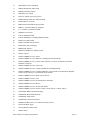
Appendix A: Earth Datum List ......................................................................................18
Appendix B: Garmin Binary Output Format ...............................................................21
Appendix C: Changing the Baud Rate in Garmin Mode.............................................24
GPS 15xH/15xL Technical Specifications
Page iii
Appendix D: Ephemeris Data download (Programming Example)............................25
Synopsis ...........................................................................................................................................................25
Garmin Binary Format Review ........................................................................................................................25
Ephemeris Download Procedure ......................................................................................................................26
Appendix E: GPS 15xH/15xL Windows Serial Mouse Issue .......................................30
Appendix F: Sensor Configuration Software ................................................................32
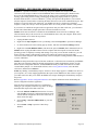
Downloading the Sensor Configuration Software............................................................................................32
Selecting a Model.............................................................................................................................................32
Connecting to the Sensor .................................................................................................................................32
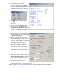
File Menu.........................................................................................................................................................33
Comm Menu ....................................................................................................................................................33
Config Menu ....................................................................................................................................................33
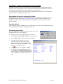
View Menu.......................................................................................................................................................34
Help Menu .......................................................................................................................................................34
LIST OF TABLES AND FIGURES
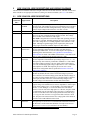
Table 1: GPS 15xH/15xL Wire Descriptions ................................................................................................. 6
Figure 1: Computer Serial Port Interconnection............................................................................................. 7
Figure 2: PDA Serial Port Interconnection..................................................................................................... 7
Figure 3: Basic NMEA Device Interconnection............................................................................................. 7
Figure 4: GPS 15xH-F & 15xL-F Dimensions............................................................................................... 8
Figure 5: GPS 15xH-W & 15xL-W Outline Drawing .................................................................................... 8
Table 2: NMEA 0183 Output Sentence Order and Size ............................................................................... 13
Table 3: Characters per Second for Available Baud Rates........................................................................... 13
GPS 15xH/15xL Technical Specifications
Page iv
1
INTRODUCTION
1.1
CAUTION
The GPS system is operated by the government of the United States, which is solely responsible for its
accuracy and maintenance. Although the GPS 15xH and GPS 15xL are precision electronic NAVigation
AIDs (NAVAIDs), any NAVAID can be misused or misinterpreted, and therefore become unsafe. Use
these products at your own risk. To reduce the risk, carefully review and understand all aspects of these
Technical Specifications before using the GPS 15xH or GPS 15xL. When in actual use, carefully compare
indications from the GPS to all available navigation sources including the information from other
NAVAIDs, visual sightings, charts, etc. For safety, always resolve any discrepancies before continuing
navigation.
FCC Compliance
This device complies with part 15 of the FCC Rules. Operation is subject to the following two conditions:
(1) this device may not cause harmful interference, and (2) this device must accept any interference
received, including interference that may cause undesired operation.
This equipment has been tested and found to comply with the limits for a Class B digital device, pursuant
to part 15 of the FCC rules. These limits are designed to provide reasonable protection against harmful
interference in a residential installation. This equipment generates, uses, and can radiate radio frequency
energy and may cause harmful interference to radio communications if not installed and used in accordance
with the instructions. However, there is no guarantee that interference will not occur in a particular
installation. If this equipment does cause harmful interference to radio or television reception, which can be
determined by turning the equipment off and on, the user is encouraged to try to correct the interference by
one of the following measures:
•
•
•
•
Reorient or relocate the receiving antenna.
Increase the separation between the equipment and the receiver.
Connect the equipment into an outlet that is on a different circuit from the receiver.
Consult the dealer or an experienced radio/TV technician for help.
This product does not contain any user-serviceable parts. Repairs should only be made by an authorized
Garmin service center. Unauthorized repairs or modifications could result in permanent damage to the
equipment, and void your warranty and your authority to operate this device under Part 15 regulations.
GPS 15xH/15xL Technical Specifications
Page 1
1.2
LIMITED WARRANTY
This Garmin product is warranted to be free from defects in materials or workmanship for one year from
the date of purchase. Within this period, Garmin will, at its sole option, repair or replace any components
that fail in normal use. Such repairs or replacement will be made at no charge to the customer for parts or
labor, provided that the customer shall be responsible for any transportation cost. This warranty does not
apply to: (i) cosmetic damage, such as scratches, nicks and dents; (ii) consumable parts, such as batteries,
unless product damage has occurred due to a defect in materials or workmanship; (iii) damage caused by
accident, abuse, misuse, water, flood, fire, or other acts of nature or external causes; (iv) damage caused by
service performed by anyone who is not an authorized service provider of Garmin; or (v) damage to a
product that has been modified or altered without the written permission of Garmin. In addition, Garmin
reserves the right to refuse warranty claims against products or services that are obtained and/or used in
contravention of the laws of any country.
This product is intended to be used only as a travel aid and must not be used for any purpose requiring
precise measurement of direction, distance, location or topography. Garmin makes no warranty as to the
accuracy or completeness of map data in this
THE WARRANTIES AND REMEDIES CONTAINED HEREIN ARE EXCLUSIVE AND IN LIEU OF
ALL OTHER WARRANTIES EXPRESS, IMPLIED, OR STATUTORY, INCLUDING ANY LIABILITY
ARISING UNDER ANY WARRANTY OF MERCHANTABILITY OR FITNESS FOR A PARTICULAR
PURPOSE, STATUTORY OR OTHERWISE. THIS WARRANTY GIVES YOU SPECIFIC LEGAL
RIGHTS, WHICH MAY VARY FROM STATE TO STATE.
IN NO EVENT SHALL GARMIN BE LIABLE FOR ANY INCIDENTAL, SPECIAL, INDIRECT, OR
CONSEQUENTIAL DAMAGES, WHETHER RESULTING FROM THE USE, MISUSE, OR
INABILITY TO USE THIS PRODUCT OR FROM DEFECTS IN THE PRODUCT. SOME STATES DO
NOT ALLOW THE EXCLUSION OF INCIDENTAL OR CONSEQUENTIAL DAMAGES, SO THE
ABOVE LIMITATIONS MAY NOT APPLY TO YOU. Garmin retains the exclusive right to repair or replace (with a new or newly-overhauled replacement
product) the device or software or offer a full refund of the purchase price at its sole discretion. SUCH
REMEDY SHALL BE YOUR SOLE AND EXCLUSIVE REMEDY FOR ANY BREACH OF
WARRANTY.
To obtain warranty service, contact your local Garmin authorized dealer or call Garmin Product Support for
shipping instructions and an RMA tracking number. Securely pack the device and a copy of the original
sales receipt, which is required as the proof of purchase for warranty repairs. Write the tracking number
clearly on the outside of the package. Send the device, freight charges prepaid, to any Garmin warranty
service station.
Online Auction Purchases: Products purchased through online auctions are not eligible for warranty
coverage. Online auction confirmations are not accepted for warranty verification. To obtain warranty
service, an original or copy of the sales receipt from the original retailer is required. Garmin will not
replace missing components from any package purchased through an online auction.
International Purchases: A separate warranty may be provided by international distributors for devices
purchased outside the United States depending on the country. If applicable, this warranty is provided by
the local in-country distributor and this distributor provides local service for your device. Distributor
warranties are only valid in the area of intended distribution. Devices purchased in the United States or
Canada must be returned to the Garmin service center in the United Kingdom, the United States, Canada,
or Taiwan for service.
GPS 15xH/15xL Technical Specifications
Page 2
1.3
OVERVIEW
The GPS 15xH and GPS 15xL sensor boards are designed for a broad spectrum of OEM (Original
Equipment Manufacturer) system applications. Based on the proven technology found in other Garmin
GPS receivers, the GPS 15xH/15xL tracks multiple satellites at a time while providing fast time-to-first-fix,
precise navigation updates, and low power consumption. The GPS 15xH/15xL includes the capability of
Wide Area Augmentation System (WAAS) differential GPS.
The GPS 15xH/15xL requires minimal additional components to be supplied by an OEM or system
integrator. A minimum system must provide the GPS with a source of power, an active GPS antenna, and a
clear view of the GPS satellites. The system may communicate with the GPS 15xH/15xL through its RS232 asynchronous serial port. End-user interfaces, such as keyboards and displays, are the responsibility of
the application designer.
1.4
FEATURES
•
GPS receiver tracks and uses multiple satellites for fast, accurate positioning and velocity estimates.
•
Compact, rugged design ideal for applications with minimal space.
•
May be remotely mounted in an out-of-the-way location.
•
User initialization is not required. Once installed, this device automatically produces navigation data.
•
On-board backup battery to maintain the non-volatile SRAM and real-time clock for up to 21 days.
•
Provision for external power to maintain the charge on the backup battery.
•
Configurable parameters include expected position, current time and date, and preferred position fix
type (2D, 3D, or automatic).
1.5
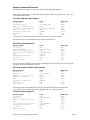
TECHNICAL SPECIFICATIONS
Specifications are subject to change without notice.
1.5.1
Physical Characteristics
1.5.1.1 Size
1.400in. (35.56 mm) wide x 1.805in. (45.85 mm) long x 0.327in. (8.31 mm) high
1.5.1.2 Weight
• GPS 15xH: 0.53 oz. (15.0 g)
•
GPS 15xL: 0.50 oz. (14.1 g)
1.5.1.3 Available Connector Options
GPS 15xH-F and GPS 15xL-F:
8-pin LIF (Low Insertion Force) flex connector, 1-millimeter pitch. For
use with common 1-mm pitch, 8-conductor flex cable, available as
Garmin Part Number 310-00040-01. This flex cable mates with
common 1 mm pitch, 8-pin flex connectors, such as Garmin part
number 330-00346-08 or Molex Part Number 52793-0890. Refer to the
Molex Web site at www.molex.com.
GPS 15xH-W and GPS 15xL-W: 8-pin JST connector, 1-mm pitch. Mating wire harness included
(Garmin Part Number 325-00118-01). The connector housing used on
this harness is equivalent to JST Part Number SHR-08V-S-B. The 8wire crimp socket is equivalent to JST Part Number SSH-003T-P0.2.
Refer to the JST Web site at www.jst.com.
1.5.1.4 Antenna Connector
The GPS 15xH and GPS 15xL series products provide an MCX female connector for connection to an
active GPS antenna. The antenna should be terminated in an MCX male connector. A suitable antenna is
Garmin’s GA 25 MCX (Garmin Part Number 010-10702-00). Other antennas that are terminated in male
BNC connectors may be adapted for use with the GPS 15xH and GPS 15xL series products by using a
Garmin MCX to BNC Adapter Cable (Garmin Part Number 010-10121-00).
GPS 15xH/15xL Technical Specifications
Page 3
1.5.2
Electrical Characteristics
1.5.2.1 Input Voltage
• GPS 15H:
8.0 Vdc to 40 Vdc unregulated
• GPS 15L: 3.3 Vdc to 5.4 Vdc (must have less than 100 mV peak-to-peak ripple)
1.5.2.2 Input Current
• GPS 15H: 60 mA peak, 50 mA nominal @ 8.0 Vdc
40 mA peak, 33 mA nominal @ 12 Vdc
15 mA peak, 12 mA nominal @ 40 Vdc
• GPS 15L: 100 mA peak, 85 mA nominal @ 3.3 to 5.0 Vdc
1.5.2.3 GPS Receiver Sensitivity
-185 dBW minimum
1.5.3
•
•
Environmental Characteristics
Operating Temperature: From -22° to 176°F (from -30° to +80°C)
Storage Temperature: From -40° to 194°F (from -40° to +90°C)
1.5.4
GPS Performance
1.5.4.1 Receiver
WAAS-enabled GPS receiver continuously tracks and uses multiple satellites to compute and update your
position.
1.5.4.2 Acquisition Times
• Reacquisition: Less than 2 seconds
• Hot:
Approx. 1 second (all data known)
• Warm:
Approx. 38 seconds (initial position, time, and almanac known; ephemeris unknown)
• Cold:
Approx. 45 seconds
1.5.4.3 Update Rate
1 second default; NMEA 0183 output interval configurable from 1 to 900 seconds in 1-second increments
1.5.4.4 Accuracy
• GPS Standard Positioning Service (SPS)
Position:
< 15 meters, 95% typical (100 meters with Selective Availability on)
Velocity:
0.1 knot RMS steady state DGPS (USCG/RTCM)
Position:
3-5 meters, 95% typical
Velocity:
0.1 knot RMS steady state
•
DGPS (WAAS)
Position:
<3 meters, 95% typical
Velocity:
0.1 knot RMS steady state
•
PPS Time:
±1 microsecond at rising edge of MPO pulse (subject to Selective Availability)
•
Dynamics:
999 knots velocity (only limited at altitude greater than 60,000 feet), 3g dynamics
1.5.5
Interfaces
1.5.5.1 GPS 15xH/15xL Electrical Characteristics
• True RS-232 output (Port 2 output not used at time of publication), asynchronous serial input
compatible with RS-232 or TTL voltage levels, RS-232 polarity.
• Factory setting is 4800 baud. User-selectable baud: 4800, 9600, 19200, 38400.
GPS 15xH/15xL Technical Specifications
Page 4
1.5.6
Antenna Specifications
The active antenna used with the GPS 15xH/15xL should have the following specifications:
Gain:
Antenna should provide between 10 dB to 30 dB net gain between the antenna
feed point and the connection to the GPS 15xH/15xL. All amplifier gains, filter
losses, cable losses, etc. must be considered when calculating the gain.
RF Connection:
GPS 15xH/15xL RF Connection: MCX Female connector (on the
GPS 15xH/15xL board)
Antenna Connection: MCX Male connector (on the end of the antenna cable)
Garmin Antenna:
GA 25 MCX (Garmin Part Number 010-10702-00) provides the required MCX
Male connector. Other Garmin antennas terminated in a BNC Male connector
may also be used if a Garmin MCX to BNC Adapter Cable (Garmin Part
Number 010-10121-00) is used. Place the MCX to BNC Adapter Cable
between the connector on the end of the antenna cable and the connector on the
GPS 15xH/15xL.
Noise Figure/Gain:
The total noise on the external antenna should be less than 3 dB with a gain
between 10 dB and 30 dB.
Should be properly biased by your choice of:
Power from on-board source: 3.0 Vdc minus the voltage drop across a 7.2 ohm series resistance due
to the current drawn by the antenna. The antenna must not draw more
than 60 mA.
Power from external source: From 3.5 Vdc to 8.0 Vdc bias through the series combination of an
on-board ~5.6 Ohm current sensing resistance, a saturated PNP silicon
transistor and a Schottky diode. The antenna must not draw more than
60 mA. The external source of antenna bias voltage should not have
any significant noise or interference power in the GPS band (20 MHz
bandwidth centered at 1.57542 GHz).
GPS 15xH/15xL Technical Specifications
Page 5
2
GPS 15XH/15XL WIRE DESCRIPTIONS AND WIRING DIAGRAMS
The GPS 15xL-F and GPS 15xH-F use an eight contact flex circuit LIF connector. The GPS 15xL-W and
GPS 15xH-W use an eight pin JST connector (mating wire harness included). (See 1.5.1.3 for details.)
2.1
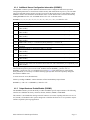
GPS 15XH/15XL WIRE DESCRIPTIONS
GPS
15xH/15xL
Pin #
1
Signal Name
BACKUP
POWER
2
3
GROUND
POWER
4
PORT 1
DATA OUT
5
PORT 1
DATA IN
6
RF BIAS
7
MPO
8
PORT 2
DATA IN
Description
This input provides external power to the battery-backed SRAM and
real-time clock. This enables the user to provide backup power if needed
for longer than the on-board rechargeable battery will provide (roughly
21 days). Input voltage must be between +2.8 and +3.4 Vdc.
Power and Signal Ground
GPS 15xL: +3.3 to +5.4 Vdc (±100 mV ripple) input. Peak operating
current is 100 mA. Nominal operating current is 85 mA. This voltage
drives an LDO with a nominal 3.0 Vdc output.
GPS 15xH: Unregulated 8.0 to 40.0 Vdc input. Peak operating current is
40 mA @ 12 Vdc input. Nominal operating current is 33 mA @ 12 Vdc
input. This voltage drives a switching regulator with a nominal 3.3 Vdc
output. Although a regulated supply is not required, the peak-to-peak
voltage ripple on this line should be kept to less than 100 mV.
Asynchronous Serial Output.
RS-232 compatible output normally provides serial data which is
formatted per NMEA 0183, Version 2.0. This output is also capable of
outputting phase data information; see Appendix B: Garmin Binary
Output Format for details. The NMEA 0183 baud rate is selectable in the
range of 300 to 38400 baud. The default baud rate is 4800.
First Asynchronous Serial Input.
RS-232 compatible with maximum input voltage range of -25 < V < 25.
This input may also be directly connected to standard 3 to 5 Vdc CMOS
logic that uses RS-232 polarity. The low signal voltage requirement is
< 0.6 Vdc, and the high signal voltage requirement is > 2.4 V. Minimum
load impedance is 500 Ω. This input may be used to receive serial
initialization/ configuration data as specified in Section 4.1 Received
NMEA 0183 Sentences.
This input allows the user to externally apply an RF bias to the active
antenna. By default, the unit will use an internal voltage to power the
active antenna. If an external voltage greater than the internal voltage of
the center pin of the antenna (between 3.5 Vdc and 8.0 Vdc) is detected
at this input, the GPS 15xH/15xL will automatically changes to the
external voltage. The antenna must not draw more than 60 mA.
Measurement Pulse Output.
Typical voltage rise and fall times are 300 ns. Impedance is 150 Ω. Open
circuit output voltage is low = 0 Vdc and high = Vin in the GPS 15xL,
and low = 0 Vdc and high = 5.0 Vdc in the GPS 15xH. The default
format is a 100 ms wide active-high pulse at a 1 Hz rate; the pulse width
is configurable in 20 ms increments. The rising edge is synchronized to
the start of each GPS second. This output provides between 800 mVp-p
to 1.7 Vp-p for GPS 15xL and 1.4 Vp-p for the GPS 15xH into a 50 Ω
load. The pulse time measured at the 50% voltage point will be about 50
ns earlier with a 50 Ω load than with no load.
Second Serial Asynchronous Input.
This input may be used to receive serial differential GPS data formatted
per RTCM SC-104 Recommended Standards For Differential Navstar
GPS Service, Version 2.2 (see Section 4.5 for more details).
Table 1: GPS 15xH/15xL Wire Descriptions
GPS 15xH/15xL Technical Specifications
Page 6
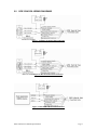
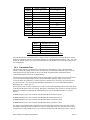
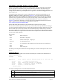
2.2
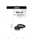
GPS 15XH/15XL WIRING DIAGRAMS
Figure 1: Computer Serial Port Interconnection
Figure 2: PDA Serial Port Interconnection
Figure 3: Basic NMEA Device Interconnection
GPS 15xH/15xL Technical Specifications
Page 7
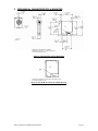
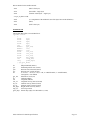
3
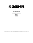
MECHANICAL CHARACTERISTICS & MOUNTING
1. Dimensions in millimeters [inches]
2. Dimension tolerance: +/-0.25 mm [±0.01in.]
3. Use M2 mounting screws.
Figure 4: GPS 15xH-F & 15xL-F Dimensions
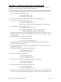
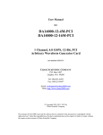
1. Dimensions identical to GPS 15xH-F and GPS 15xL-F
2. Use M2 mounting screws.
Figure 5: GPS 15xH-W & 15xL-W Outline Drawing
GPS 15xH/15xL Technical Specifications
Page 8
4
GPS 15XH/15XL SOFTWARE INTERFACE
The factory default interface protocol of the GPS 15xH/15xL serial com port 1 is based on the National
Marine Electronics Association’s NMEA 0183 ASCII interface specification. This standard is fully defined
in NMEA 0183, Version 2.30. Copies may be obtained from NMEA, www.nmea.org.
In addition to the standard NMEA 0183 sentences, the GPS 15xH/15xL may also be configured to transmit
information over their serial interface using NMEA 0183 compliant Garmin proprietary sentences. These
proprietary sentences begin with the characters, “$PGRM”, instead of the characters “$G” that are typical
of the standard NMEA 0183 sentences. The characters “$P” indicate that the sentence is a proprietary
implementation and the characters and “GRM” indicate that it is Garmin’s proprietary sentence. The
character (or characters) that follow the characters “$PGRM” uniquely identifies that particular Garmin
proprietary sentence.
It is also possible to configure the GPS 15xH/15xL to transmit Garmin binary data over their serial com
port 1 interface. See Appendix B: Garmin Binary Output Format for details.
The following sections describe the NMEA 0183 data format of each sentence transmitted and received by
the GPS 15xH/15xL.
4.1
RECEIVED NMEA 0183 SENTENCES
The following paragraphs define the sentences that can be received on the GPS sensors’ port. Null fields in
the configuration sentence indicate no change in the particular configuration parameter. All sentences
received by the GPS sensor must be terminated with <CR><LF>. Please note that <CR> and <LF> denote
the ASCII characters for carriage return (0D hexadecimal) and line feed (0A hexadecimal), respectively.
So, <CR> and <LF> are each transmitted as single bytes.
The checksum *hh is used for parity checking data and is not required, but is recommended for use in
environments containing high electromagnetic noise. It is generally not required in normal PC
environments. When used, the parity bytes (hh) are the ASCII representation of the upper and lower nibbles
of the exclusive-or (XOR) parity, computed over all of the characters between the “$” and “*” characters,
non-inclusive. The hexadecimal representation uses capital letters, such as 3D instead of 3d. Sentences may
be truncated by <CR><LF> after any data field and valid fields up to that point will be acted on by the
sensor.
4.1.1
Almanac Information (ALM)
The $GPALM sentence can be used to initialize the GPS sensor’s stored almanac information in the event
of non-volatile memory loss or after storing longer than six months without tracking GPS satellites.
$GPALM,<1>,<2>,<3>,<4>,<5>,<6>,<7>,<8>,<9>,<10>,<11>,<12>,<13>,<14>,<15>*hh<CR><LF>
<1>
<2>
<3>
<4>
<5>
<6>
<7>
<8>
<9>
<10>
<11>
<12>
<13>
<14>
<15>
Total number of ALM sentences to be transmitted by the GPS sensor during almanac download.
This field can be null or any number when sending almanac to the GPS sensor.
Number of current ALM sentence. This field can be null or any number when sending almanac
to the GPS sensor.
Satellite PRN number, 01 to 32
GPS week number
SV health, bits 17–24 of each almanac page
Eccentricity
Almanac reference time
Inclination angle
Rate of right ascension
Root of semi major axis
Omega, argument of perigee
Longitude of ascension node
Mean anomaly
af0 clock parameter
af1 clock parameter
GPS 15xH/15xL Technical Specifications
Page 9
4.1.2
Sensor Initialization Information (PGRMI)
The $PGRMI sentence provides information used to initialize the GPS sensor’s last known position and to
set the time on the real time clock. This information is used by the GPS receiver on the next power cycle to
predict which satellites will be visible in the sky as an aid for more rapid satellite acquisition. Receipt of
this sentence by the GPS sensor during satellite acquisition causes the software to restart the satellite
acquisition process. If there are no errors in the sentence, it will be echoed upon receipt. If an error is
detected, the echoed PGRMI sentence will contain the current default values. Current PGRMI defaults
(with the exception of the Receiver Command, which is a command rather than a mode) can also be
obtained by sending $PGRMIE<CR><LF> or $PGRMIE*04<CR><LF> to the GPS sensor.
$PGRMI,<1>,<2>,<3>,<4>,<5>,<6>,<7>*hh<CR><LF>
<1>
<2>
<3>
<4>
<5>
<6>
<7>
4.1.3
Latitude, ddmm.mmm format (leading zeros must be transmitted)
Latitude hemisphere, N or S
Longitude, dddmm.mmm format (leading zeros must be transmitted)
Longitude hemisphere, E or W
Current UTC date, ddmmyy format
Current UTC time, hhmmss format
Receiver Command, A = Auto Locate, R = Unit Reset
Sensor Configuration Information (PGRMC)
The $PGRMC sentence provides information used to configure the GPS sensor’s operation. Configuration
parameters are stored in non-volatile memory and retained between power cycles. The GPS sensor will
echo this sentence upon its receipt if no errors are detected. If an error is detected, the echoed PGRMC
sentence will contain the current default values. Current default values can also be obtained by sending
$PGRMCE<CR><LF> or $PGRMCE*0E<CR><LF> to the GPS sensor.
$PGRMC,<1>,<2>,<3>,<4>,<5>,<6>,<7>,<8>,<9>,<10>,<11>,<12>,<13>,<14>*hh<CR><LF>
<1>
<2>
<3>
Fix mode, A = Automatic, 3 = 3D exclusively
Altitude above/below mean sea level, -1500.0 to 18000.0 meters
Earth datum index. If the user datum index (96) is specified, fields <4> through <8> must contain
valid values. Otherwise, fields <4> through <8> must be null. Refer to Appendix A: Earth Datum List
for a list of earth datum and the corresponding earth datum index.
<4>
User earth datum semi-major axis, 6360000.000 to 6380000.000 meters (.001 meters resolution)
<5>
User earth datum inverse flattening factor, 285.0 to 310.0 (10-9 resolution)
<6>
User earth datum delta x earth centered coordinate, -5000.0 to 5000.0 meters (1 meter resolution)
<7>
User earth datum delta y earth centered coordinate, -5000.0 to 5000.0 meters (1 meter resolution)
<8>
User earth datum delta z earth centered coordinate, -5000.0 to 5000.0 meters (1 meter resolution)
<9>
Differential mode, A = Automatic (output DGPS data when available, non-DGPS otherwise), D =
Differential exclusively (output only differential fixes)
<10> NMEA 0183 Baud rate, 3 = 4800, 4 = 9600, 5 = 19200, 8 = 38400
<11> No Effect (This field is not used on the GPS 15xH/15xL and is included only for compatibility with
other models.)
<12> PPS mode, 1 = No PPS, 2 = 1 Hz
<13> PPS pulse length, 0-48 = (n+1)*20 ms. Example: n = 4 corresponds to a 100 ms wide pulse
<14> Dead reckoning valid time 1 to 30 seconds
All configuration changes take effect after receipt of a valid value except baud rate. Baud rate changes take
effect on the next power cycle or an external reset event.
GPS 15xH/15xL Technical Specifications
Page 10
4.1.4
Additional Sensor Configuration Information (PGRMC1)
The $PGRMC1 sentence provides additional information used to configure the GPS sensor operation.
Configuration parameters are stored in non-volatile memory and retained between power cycles. The GPS
sensor will echo this sentence upon its receipt if no errors are detected. If an error is detected, the echoed
PGRMC1 sentence will contain the current default values. Current default values can also be obtained by
sending $PGRMC1E<CR><LF> or PGRMC1E*3F<CR><LF> to the GPS sensor.
$PGRMC1,<1>,<2>,<3>,<4>,<5>,<6>,<7>,<8>,<9>,<10>,<11>,<12>,<13>*hh<CR><LF>
<1>
<2>
<3>
NMEA 0183 output time 1 to 900 (sec).
Garmin Binary Output, 1 = Off, 2 = On.
No Effect (This field is not used on the GPS 15xH/15xL and is included only for compatibility with
other models.)
<4>
No Effect (This field is not used on the GPS 15xH/15xL and is included only for compatibility with
other models.)
<5>
No Effect (This field is not used on the GPS 15xH/15xL and is included only for compatibility with
other models.)
<6>
No Effect (This field is not used on the GPS 15xH/15xL and is included only for compatibility with
other models.)
<7>
NMEA 0183 version, 1 = version 2.20 (factory default), 2 = version 2.30
<8>
DGPS WAAS mode, A = Automatic, W = WAAS Only , R = RTCM Only, N = None (DGPS
Disabled)
<9>
Power Save Mode, P = Power Save mode, N = Normal
<10> No Effect (This field is not used on the GPS 15xH/15xL and is included only for compatibility with
other models.)
<11> No Effect (This field is not used on the GPS 15xH/15xL and is included only for compatibility with
other models.)
<12> No Effect (This field is not used on the GPS 15xH/15xL and is included only for compatibility with
other models.)
<13> PPS Auto Off Mode, 1 = Off, 2 = On
<14> No Effect (This field is not used on the GPS 15xH/15xL and is included only for compatibility with
other models.)
Configuration changes take effect immediately, with the exception of Garmin Binary Output, which takes
effect on the next power cycle or a reset event. Send the sentence $PGRMI,,,,,,,R<CR><LF> or
$PGRMI,,,,,,R*3F<CR><LF> to command a reset (refer to 4.1.2). If the GPS sensor is in the Garmin
binary data mode, it is necessary to send the following eight-byte data stream to temporarily change the
data format to NMEA 0183:
10 0A 02 26 00 CE 10 03 (Hexadecimal)
Follow by sending a PGRMC1 sentence that turns off the Garmin Binary Output format:
$PGRMC1,,1<CR><LF> or $PGRMC1,,1*4B<CR><LF>
4.1.5
Output Sentence Enable/Disable (PGRMO)
The $PGRMO sentence provides the ability to enable and disable specific output sentences. The following
sentences are enabled at the factory: GPGGA, GPGSA, GPGSV, GPRMC, and PGRMT.
This sentence is not intended for turning on and off sentences as a means of polling while the receiver is in
use; instead, it is intended to allow systems integrators to initialize the GPS receiver so it produces only the
sentences required by the target application.
GPS 15xH/15xL Technical Specifications
Page 11
$PGRMO,<1>,<2>*hh<CR><LF>
<1>
<2>
Target sentence description (for example, PGRMT, GPGSV, etc.)
Target sentence mode, where:
0 = Disable specified sentence,
1 = enable specified sentence,
2 = Disable all output sentences,
3 = Enable all output sentences (except GPALM),
4 = Restore factory default output sentences
The following notes apply to the PGRMO input sentence:
If the target sentence mode is “2” (Disable all), “3” (Enable all), or “4” (Restore defaults), the target
sentence description is not checked for validity. In this case, an empty field is allowed (for example,
$PGRMO,,3), or the mode field may contain from 1 to 5 characters.
If the target sentence mode is “0” (Disable) or “1” (Enable), the target sentence description field must be an
identifier for one of the sentences that can be output by the GPS sensor.
If either the target sentence mode field or the target sentence description field is not valid, the PGRMO
sentence will have no effect.
$PGRMO,GPALM,1<CR><LF> will cause the GPS sensor to transmit all stored almanac information. All
other NMEA 0183 sentence transmission will be suspended temporarily.
$PGRMO,,G<CR><LF> will cause the COM port to change to Garmin Binary Output mode for the
duration of the power cycle or until 10 0A 02 26 00 CE 10 03 (Hexadecimal) is sent to the GPS receiver in
order to return to NMEA 0183 mode as described in Section 4.1.4 . Garmin binary mode is required for
GPS 15xH/15xL series product software updates.
4.2
TRANSMITTED NMEA 0183 SENTENCES
The subsequent paragraphs define the sentences that can be transmitted on COM 1 by the GPS sensor.
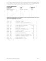
4.2.1
Sentence Transmission
Sentences are transmitted with respect to the user selected baud rate.
Regardless of the selected baud rate, the information transmitted by the GPS sensor is referenced to
theUTC second boundary immediately preceding the GPRMC sentence, or whichever sentence is
output first in the burst (see Table 3 below).
The GPS sensor will transmit each sentence (except where noted in particular transmitted sentence
descriptions) at a periodic rate based on the user selected baud rate and user selected output sentences. The
GPS sensor will transmit the selected sentences contiguously. The length of the transmission can be
determined by the following equation and Tables 3 and 4:
length of transmission
=
GPS 15xH/15xL Technical Specifications
total characters to be transmitted
--------------------------------------------characters transmitted per second
Page 12
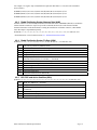
Sentence
Output by Default?
Maximum Characters
9
GPRMC
74
9
GPGGA
82
9
GPGSA
66
9
GPGSV
70
PGRME
35
GPGLL
44
GPVTG
42
PGRMV
32
PGRMF
82
PGRMB
40
PGRMM
32
PGRMT
Once per minute
50
Table 2: NMEA 0183 Output Sentence Order and Size
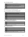
Baud
Characters per Second
4800
480
9600
960
19200
1920
38400
3840
Table 3: Characters per Second for Available Baud Rates
The maximum number of fields allowed in a single sentence is 82 characters including delimiters. Values
in the table include the sentence start delimiter character “$” and the termination delimiter <CR><LF>. The
factory set defaults result in a once per second transmission at the NMEA 0183 specification transmission
rate of 4800 baud.
4.2.2
Transmitted Time
The GPS sensor outputs Coordinated Universal Time (UTC) date and time of day in the transmitted
sentences. Before the initial position fix, the on-board clock provides the date and time of day. After the
initial position fix, the date and time of day are calculated using GPS satellite information and are
synchronized with the closest UTC second boundary.
The GPS sensor uses information obtained from the GPS satellites to add or delete UTC leap seconds and
correct the transmitted date and time of day. The transmitted date and time of day for leap second
correction follow the guidelines in “National Institute of Standards and Technology Special Publication
432 (Revised 1990)” (for sale by the Superintendent of Documents, U.S. Government Printing Office,
Washington, D.C., 20402, U.S.A.).
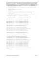
When a positive leap second is required, one second is inserted at the beginning of the first hour (0h 0m 0s)
of the day that the positive leap is occurring. The minute containing the leap second is 61 seconds long. The
GPS sensor would have transmitted this information for the leap second added December 31, 1998 as
follows:
$GPRMC,235959,A,3851.3651,N,09447.9382,W,000.0,000.0,311298,003.3,E*65
$GPRMC,000000,A,3851.3651,N,09447.9382,W,000.0,000.0,010199,003.3,E*64
$GPRMC,000000,A,3851.3651,N,09447.9382,W,000.0,000.0, 010199,003.3,E*64
$GPRMC,000001,A,3851.3651,N,09447.9382,W,000.0,000.0, 010199,003.3,E*65
If a negative leap second should be required, one second will be deleted at the end of some UTC month.
The minute containing the leap second will be only 59 seconds long. In this case, the GPS sensor will not
transmit the time of day 0h 0m 0s (the “zero” second) for the day from which the leap second is removed.
GPS 15xH/15xL Technical Specifications
Page 13
For example, if a negative leap second had been required on December 31, 1998, the result would have
been as follows:
$GPRMC,235959,A,3851.3651,N,09447.9382,W,000.0,000.0,311298,003.3,E*65
$GPRMC,000001,A,3851.3651,N,09447.9382,W,000.0,000.0,010199,003.3,E*65
$GPRMC,000002,A,3851.3651,N,09447.9382,W,000.0,000.0,010199,003.3,E*66
4.2.3
Global Positioning System Almanac Data (ALM)
Almanac sentences are not normally transmitted. Send the GPS sensor a $PGRMO,GPALM,1 command to
initiate almanac transmission. Upon receipt of this command, the GPS sensor will transmit available
almanac information on GPALM sentences. During the transmission of almanac sentences, other NMEA
0183 data output is suspended temporarily.
$GPALM,<1>,<2>,<3>,<4>,<5>,<6>,<7>,<8>,<9>,<10>,<11>,<12>,<13>,<14>,<15>*hh<CR><LF>
<field information> can be found in Section 4.1.1 Almanac Information (ALM).
4.2.4
Global Positioning System Fix Data (GGA)
$GPGGA,<1>,<2>,<3>,<4>,<5>,<6>,<7>,<8>,<9>,M,<10>,M,<11>,<12>*hh<CR><LF>
<1>
<2>
<3>
<4>
<5>
<6>
<7>
<8>
<9>
<10>
<11>
<12>
4.2.5
UTC time of position fix, hhmmss format
Latitude, ddmm.mmmm format (leading zeros will be transmitted)
Latitude hemisphere, N or S
Longitude, dddmm.mmmm format (leading zeros will be transmitted)
Longitude hemisphere, E or W
GPS quality indication, 0 = fix not available, 1 = Non-differential GPS fix available, 2 =
Differential GPS (WAAS) fix available, 6 = Estimated
Number of satellites in use, 00 to 12 (leading zeros will be transmitted)
Horizontal dilution of precision, 0.5 to 99.9
Antenna height above/below mean sea level, -9999.9 to 99999.9 meters
Geoidal height, -999.9 to 9999.9 meters
Null (Differential GPS)
Null (Differential Reference Station ID)
GPS DOP and Active Satellites (GSA)
$GPGSA,<1>,<2>,<3>,<3>,<3>,<3>,<3>,<3>,<3>,<3>,<3>,<3>,<3>,<3>,<4>,<5>,<6>*hh<CR><LF>
<1>
<2>
<3>
<4>
<5>
<6>
Mode, M = Manual, A = Automatic
Fix type, 1 = not available, 2 = 2D, 3 = 3D
PRN number, 01 to 32, of satellite used in solution, set to null if unused (leading zeros will be
transmitted)
Position dilution of precision, 0.5 to 99.9
Horizontal dilution of precision, 0.5 to 99.9
Vertical dilution of precision, 0.5 to 99.9
GPS 15xH/15xL Technical Specifications
Page 14
4.2.6
GPS Satellites in View (GSV)
$GPGSV,<1>,<2>,<3>,<4>,<5>,<6>,<7>,...<4>,<5>,<6>,<7>*hh<CR><LF>
<1>
Total number of GSV sentences to be transmitted
<2>
Number of current GSV sentence
<3>
Total number of satellites in view, 00 to 12 (leading zeros will be transmitted)
<4>
Satellite PRN number, 01 to 32 (leading zeros will be transmitted)
<5>
Satellite elevation, 00 to 90 degrees (leading zeros will be transmitted)
<6>
Satellite azimuth, 000 to 359 degrees, true (leading zeros will be transmitted)
<7>
Signal to noise ratio (C/No) 00 to 99 dB (leading zeros will be transmitted)
Note: Items <4>,<5>,<6>, and <7> repeat for each satellite in view to a maximum of four (4) satellites per
sentence. Additional satellites in view information must be sent in subsequent GPGSV sentences.
Individual fields may be set to null if the corresponding data is unavailable.
4.2.7
Recommended Minimum Specific GPS/TRANSIT Data (RMC)
$GPRMC,<1>,<2>,<3>,<4>,<5>,<6>,<7>,<8>,<9>,<10>,<11>,<12>*hh<CR><LF>
<1>
<2>
<3>
<4>
<5>
<6>
<7>
<8>
<9>
<10>
<11>
<12>
4.2.8
UTC time of position fix, hhmmss format
Status, A = Valid position, V = NAV receiver warning
Latitude, ddmm.mmmm format (leading zeros will be transmitted)
Latitude hemisphere, N or S
Longitude, dddmm.mmmm format (leading zeros will be transmitted)
Longitude hemisphere, E or W
Speed over ground, 000.0 to 999.9 knots (leading zeros will be transmitted)
Course over ground, 000.0 to 359.9 degrees, true (leading zeros will be transmitted)
UTC date of position fix, ddmmyy format
Magnetic variation, 000.0 to 180.0 degrees (leading zeros will be transmitted)
Magnetic variation direction, E or W (westerly variation adds to true course)
Mode indicator (only output if NMEA 0183 version 2.30 active), A = Autonomous, D =
Differential, E + Estimated, N = Data not valid
Track Made Good and Ground Speed (VTG)
$GPVTG,<1>,T,<2>,M,<3>,N,<4>,K,<5>*hh<CR><LF>
<1>
<2>
<3>
<4>
<5>
4.2.9
True course over ground: 000 to 359 degrees (leading zeros will be transmitted)
Magnetic course over ground: 000 to 359 degrees (leading zeros will be transmitted)
Speed over ground: 000.0 to 999.9 knots (leading zeros will be transmitted)
Speed over ground: 0000.0 to 1851.8 kilometers per hour (leading zeros will be transmitted)
Mode indicator (only output if NMEA 0183 version 2.30 active), A = Autonomous,
D = Differential, E = Estimated, N = Data not valid
Geographic Position (GLL)
$GPGLL,<1>,<2>,<3>,<4>,<5>,<6>,<7>*hh<CR><LF>
<1>
<2>
<3>
<4>
<5>
<6>
<7>
Latitude, ddmm.mmmm format (leading zeros must be transmitted)
Latitude hemisphere, N or S
Longitude, dddmm.mmmm format (leading zeros must be transmitted)
Longitude hemisphere, E or W
UTC time of position fix, hhmmss format
Status, A = Valid position, V = NAV receiver warning
Mode indicator (only output if NMEA 0183 version 2.30 active), A = Autonomous,
D = Differential (WAAS), E = Estimated, N = Data not valid
GPS 15xH/15xL Technical Specifications
Page 15
4.2.10 Estimated Error Information (PGRME)
$PGRME,<1>,M,<2>,M,<3>,M*hh<CR><LF>
<1>
<2>
<3>
Estimated horizontal position error (HPE), 0.0 to 999.9 meters
Estimated vertical position error (VPE), 0.0 to 999.9 meters
Estimated position error (EPE), 0.0 to 999.9 meters
4.2.11 GPS Fix Data Sentence (PGRMF)
$PGRMF,<1>,<2>,<3>,<4>,<5>,<6>,<7>,<8>,<9>,<10>,<11>,<12>,<13>,<14>,<15>*hh<CR><LF>
<1>
<2>
<3>
<4>
<5>
<6>
<7>
<8>
<9>
<10>
<11>
<12>
<13>
<14>
<15>
GPS week number (0 to 1023)
GPS seconds (0 to 604799)
UTC date of position fix, ddmmyy format
UTC time of position fix, hhmmss format
GPS leap second count
Latitude, ddmm.mmmm format (leading zeros must be transmitted)
Latitude hemisphere, N or S
Longitude, dddmm.mmmm format (leading zeros must be transmitted)
Longitude hemisphere, E or W
Mode, M = Manual, A = Automatic
Fix type, 0 = no fix, 1 = 2D fix, 2 = 3D fix
Speed over ground, 0 to 1851 kilometers/hour
Course over ground, 0 to 359 degrees, true
Position dilution of precision, 0 to 9 (rounded to nearest integer value)
Time dilution of precision, 0 to 9 (rounded to nearest integer value)
4.2.12 Map Datum (PGRMM)
The Garmin Proprietary sentence $PGRMM gives the name of the map datum currently in use by the GPS
sensor. This information is used by the Garmin MapSource real-time plotting application.
$PGRMM,<1>*hh<CR><LF>
<1>
Name of map datum currently in use (variable length field, for example, “WGS 84”)
GPS 15xH/15xL Technical Specifications
Page 16
4.2.13 Sensor Status Information (PGRMT)
The Garmin Proprietary sentence $PGRMT gives information concerning the status of the GPS sensor.
This sentence is transmitted once per minute regardless of the selected baud rate.
$PGRMT,<1>,<2>,<3>,<4>,<5>,<6>,<7>,<8>,<9>*hh<CR><LF>
<1>
<2>
<3>
<4>
<5>
<6>
<7>
<8>
<9>
Product, model and software version (variable length field, for example, “GPS 15xH/15xL VER
2.05”)
No Effect (This field is not used on the GPS 15xH/15xL and is included only for compatibility with
other models.)
No Effect (This field is not used on the GPS 15xH/15xL and is included only for compatibility with
other models.)
No Effect (This field is not used on the GPS 15xH/15xL and is included only for compatibility with
other models.)
No Effect (This field is not used on the GPS 15xH/15xL and is included only for compatibility with
other models.)
No Effect (This field is not used on the GPS 15xH/15xL and is included only for compatibility with
other models.)
No Effect (This field is not used on the GPS 15xH/15xL and is included only for compatibility with
other models.)
No Effect (This field is not used on the GPS 15xH/15xL and is included only for compatibility with
other models.)
No Effect (This field is not used on the GPS 15xH/15xL and is included only for compatibility with
other models.)
4.2.14 3D Velocity Information (PGRMV)
$PGRMV,<1>,<2>,<3>*hh<CR><LF>
<1>
<2>
<3>
True east velocity, -514.4 to 514.4 meters/second
True north velocity, -514.4 to 514.4 meters/second
Up velocity, -999.9 to 999.9 meters/second
4.2.15 DGPS Beacon Information (PGRMB)
$PGRMB,<1>,<2>,<3>,<4>,<5>,K,<6>,<7>,<8>*hh<CR><LF>
<1>
<2>
<3>
<4>
<5>
<6>
<7>
<8>
No Effect (This field is not used on the GPS 15xH/15xL and is included only for compatibility with
other models.)
No Effect (This field is not used on the GPS 15xH/15xL and is included only for compatibility with
other models.)
No Effect (This field is not used on the GPS 15xH/15xL and is included only for compatibility with
other models.)
No Effect (This field is not used on the GPS 15xH/15xL and is included only for compatibility with
other models.)
Distance to beacon reference station in kilometers
No Effect (This field is not used on the GPS 15xH/15xL and is included only for compatibility with
other models.)
DGPS fix source: R = RTCM, W = WAAS, N = No DGPS fix available
Currently selected DGPS mode as specified by the PGRMC1 sentence of Section 4.1.4: A =
Automatic (factory default), W = WAAS only, R = RTCM only, N = None (No DGPS enabled)
GPS 15xH/15xL Technical Specifications
Page 17
APPENDIX A: EARTH DATUM LIST
The following is a list of the Garmin GPS 15xH/15xL Earth datum indices and the corresponding earth
datum name (including the area of application):
0
ADINDAN–Ethiopia, Mali, Senegal, Sudan
1
AFGOOYE - Somalia
2
AIN EL ABD 1970 - Bahrain Island, Saudi Arabia
3
ANNA 1 ASTRO 1965 - Cocos Island
4
ARC 1950 - Botswana, Lesotho, Malawi, Swaziland, Zaire, Zambia, Zimbabwe
5
ARC 1960 - Kenya, Tanzania
6
ASCENSION ISLAND 1958 - Ascension Island
7
ASTRO BEACON E - Iwo Jima Island
8
AUSTRALIAN GEODETIC 1966 - Australia, Tasmania Island
9
AUSTRALIAN GEODETIC 1984–Australia, Tasmania Island
10
ASTRO DOS 71/4–St. Helena Island
11
ASTRONOMIC STATION 1952–Marcus Island
12
ASTRO B4 SOROL ATOLL–Tern Island
13
BELLEVUE (IGN)–Efate and Erromango Islands
14
BERMUDA 1957–Bermuda Islands
15
BOGOTA OBSERVATORY–Colombia
16
CAMPO INCHAUSPE–Argentina
17
CANTON ASTRO 1966–Phoenix Islands
18
CAPE CANAVERAL–Florida, Bahama Islands
19
CAPE–South Africa
20
CARTHAGE–Tunisia
21
CHATHAM 1971–Chatham Island (New Zealand)
22
CHUA ASTRO–Paraguay
23
CORREGO ALEGRE–Brazil
24
DJAKARTA (BATAVIA)–Sumatra Island (Indonesia)
25
DOS 1968–Gizo Island (New Georgia Islands)
26
EASTER ISLAND 1967–Easter Island
27
EUROPEAN 1950–Austria, Belgium, Denmark, Finland, France, Germany, Gibraltar, Greece,
Italy, Luxembourg, Netherlands, Norway, Portugal, Spain, Sweden, Switzerland
28
EUROPEAN 1979–Austria, Finland, Netherlands, Norway, Spain, Sweden, Switzerland
29
FINLAND HAYFORD 1910–Finland
30
GANDAJIKA BASE–Republic of Maldives
31
GEODETIC DATUM 1949–New Zealand
32
ORDNANCE SURVEY OF GREAT BRITAIN 1936–England, Isle of Man, Scotland, Shetland
Islands, Wales
33
GUAM 1963–Guam Island
34
GUX 1 ASTRO–Guadalcanal Island
35
HJORSEY 1955–Iceland
GPS 15xH/15xL Technical Specifications
Page 18
36
HONG KONG 1963–Hong Kong
37
INDIAN–Bangladesh, India, Nepal
38
INDIAN–Thailand, Vietnam
39
IRELAND 1965–Ireland
40
ISTS O73 ASTRO 1969–Diego Garcia
41
JOHNSTON ISLAND 1961–Johnston Island
42
KANDAWALA–Sri Lanka
43
KERGUELEN ISLAND–Kerguelen Island
44
KERTAU 1948–West Malaysia, Singapore
45
L.C. 5 ASTRO–Cayman Brac Island
46
LIBERIA 1964–Liberia
47
LUZON–Mindanao Island
48
LUZON–Phillippines (excluding Mindanao Island)
49
MAHE 1971–Mahe Island
50
MARCO ASTRO–Salvage Islands
51
MASSAWA–Eritrea (Ethiopia)
52
MERCHICH–Morocco
53
MIDWAY ASTRO 1961–Midway Island
54
MINNA–Nigeria
55
NORTH AMERICAN 1927–Alaska
56
NORTH AMERICAN 1927–Bahamas (excluding San Salvador Island)
57
NORTH AMERICAN 1927–Central America (Belize, Costa Rica, El Salvador, Guatemala,
Honduras, Nicaragua)
58
NORTH AMERICAN 1927–Canal Zone
59
NORTH AMERICAN 1927–Canada (including Newfoundland Island)
60
NORTH AMERICAN 1927–Caribbean (Barbados, Caicos Islands, Cuba, Dominican Republic,
Grand Cayman, Jamaica, Leeward Islands, Turks Islands)
61
NORTH AMERICAN 1927–Mean Value (CONUS)
62
NORTH AMERICAN 1927–Cuba
63
NORTH AMERICAN 1927–Greenland (Hayes Peninsula)
64
NORTH AMERICAN 1927–Mexico
65
NORTH AMERICAN 1927–San Salvador Island
66
NORTH AMERICAN 1983–Alaska, Canada, Central America, CONUS, Mexico
67
NAPARIMA, BWI–Trinidad and Tobago
68
NAHRWAN–Masirah Island (Oman)
69
NAHRWAN–Saudi Arabia
70
NAHRWAN–United Arab Emirates
71
OBSERVATORIO 1966–Corvo and Flores Islands (Azores)
72
OLD EGYPTIAN–Egypt
73
OLD HAWAIIAN–Mean Value
74
OMAN–Oman
GPS 15xH/15xL Technical Specifications
Page 19
75
PICO DE LAS NIEVES–Canary Islands
76
PITCAIRN ASTRO 1967–Pitcairn Island
77
PUERTO RICO–Puerto Rico, Virgin Islands
78
QATAR NATIONAL–Qatar
79
QORNOQ–South Greenland
80
REUNION–Mascarene Island
81
ROME 1940–Sardinia Island
82
RT 90–Sweden
83
PROVISIONAL SOUTH AMERICAN 1956–Bolivia, Chile, Colombia, Ecuador, Guyana, Peru,
Venezuela
84
SOUTH AMERICAN 1969–Argentina, Bolivia, Brazil, Chile, Colombia, Ecuador, Guyana,
Paraguay, Peru, Venezuela, Trinidad and Tobago
85
SOUTH ASIA–Singapore
86
PROVISIONAL SOUTH CHILEAN 1963–South Chile
87
SANTO (DOS)–Espirito Santo Island
88
SAO BRAZ–Sao Miguel, Santa Maria Islands (Azores)
89
SAPPER HILL 1943–East Falkland Island
90
SCHWARZECK–Namibia
91
SOUTHEAST BASE–Porto Santo and Madeira Islands
92
SOUTHWEST BASE–Faial, Graciosa, Pico, Sao Jorge, and Terceira Islands (Azores)
93
TIMBALAI 1948–Brunei and East Malaysia (Sarawak and Sabah)
94
TOKYO–Japan, Korea, Okinawa
95
TRISTAN ASTRO 1968–Tristan da Cunha
96
User defined earth datum
97
VITI LEVU 1916–Viti Levu Island (Fiji Islands)
98
WAKE-ENIWETOK 1960–Marshall Islands
99
WORLD GEODETIC SYSTEM 1972
100
WORLD GEODETIC SYSTEM 1984
101
ZANDERIJ–Surinam
102
CH-1903–Switzerland
103
Hu-Tzu-Shan
104
Indonesia 74
105
Austria
106
Potsdam
107
Taiwan–modified Hu-Tzu-Shan
108
GDA–Geocentric Datum of Australia
109
Dutch
GPS 15xH/15xL Technical Specifications
Page 20
APPENDIX B: GARMIN BINARY OUTPUT FORMAT
In binary output mode, the GPS 15xH/15xL will transmit packets once per second. The record contains
primarily post-process information such as position and velocity information. The default serial port
settings in binary output mode is 4800 baud, 8 data bits, 1 start bit, 1 stop bit and no parity. Of those
settings, only the baud rate may be changed. Please see Appendix C for details on changing the baud rate in
binary output mode.
To enable the binary output mode as a power-on default (powers up with this mode enabled), use the
$PGRMC1 NMEA 0183 sentence as described in Section 4.1.4. (You must currently be operating in
NMEA 0183 mode in order for NMEA 0183 configuration sentences to have any effect.) If you wish to
enable the binary output mode and you do not wish to alter the setting for which mode (NMEA 0183 or
binary output) is enabled at power on, use the $PGRMO NMEA 0183 sentence as described in
Section 4.1.5. Refer to the Garmin Device Interface Specification found in the Garmin Device Interface
SDK for details on how to form and parse Garmin packets, available at
www.garmin.com/support/commProtocol.html.
Note that the satellite data information is also enabled when the position record is enabled.
Records sent over RS232 begin with a delimiter byte (10 hex). The second byte identifies the record type
(33 hex for a position record and 72 hex for a satellite data record). The third byte indicates the size of the
data. The fourth byte is the first byte of data. The data is then followed by a checksum byte, a delimiter
byte (10 hex), and an end-of-transmission character (03 hex). Additionally, any DLEs (0x10) that appear
between the delimeters are escaped with a second DLE. There is sample code at the end of this section that
will strip off the DLEs and ETXs.
RS232 Packet:
- 0x10
(DLE is first byte)
- 0x##
(Record ID – single byte)
- 0x##
(Number of data bytes – single byte)
- data bytes
(See descriptions below)
- 0x##
(2’s complement of the arithmetic sum of the bytes between the delimiters)
- 0x10
(DLE)
- 0x03
(ETX is last byte)
The data bytes of each packet contain the record specified by the record ID. A description of each record
follows.
Satellite Data Record
The satellite data has a record ID of 0x72 with 84 (0x54) data bytes. The data bytes contain data for 12
satellites as described below.
typedef
struct
{
uint8
svid; //space vehicle identification (1–32 and 33–64 for
WAAS)
uint16
snr;
//signal-to-noise ratio
uint8
elev; //satellite elevation in degrees
uint16
azmth;
//satellite azimuth in degrees
uint8
status; //status bit-field
} cpo_sat_data;
The status bit field represents a set of Booleans described below:
Bit
Meaning when bit is one (1)
0
The unit has ephemeris data for the specified satellite.
1
The unit has a differential correction for the specified satellite.
2
The unit is using this satellite in the solution.
This pattern is repeated for 12 satellites for a total of 12 × 7 bytes = 84 (0x54) bytes.
GPS 15xH/15xL Technical Specifications
Page 21
RS-232 Packet for the Satellite Record:
- 0x10
(DLE is first byte)
- 0x72
(Record ID – single byte)
- 0x54
(Number of data bytes – single byte)
- 12 cpo_sat_data records:
- 0x##
(2’s complement of the arithmetic sum of the bytes between the delimiters)
- 0x10
(DLE)
- 0x03
(ETX is last byte)
Position Record
The Position Record has a record identifier of
typedef struct
{
float
alt;
float
epe;
float
eph;
float
epv;
int
fix;
double
gps_tow;
double
lat;
double
lon;
float
lon_vel;
float
lat_vel;
float
alt_vel;
float
msl_hght;
int
leap_sec;
long
grmn_days;
} cpo_pvt_data;
alt
epe
eph
epv
fix
Ellipsoid altitude (meters)
Estimated position error (meters)
Position error, horizontal (meters)
Position error, vertical (meters)
0 = no fix; 1 = no fix; 2 = 2D; 3 = 3D; 4 = 2D differential; 5 = 3D differential;
6 and greater = not defined
gps_tow
GPS time of week (sec)
lat
Latitude (radians)
lon
Longitude (radians)
lon_vel
Longitude velocity (meters/second)
lat_vel
Latitude velocity (meters/second)
alt_vel
Altitude velocity (meters/second)
msl_hght
Height (mean sea level) (meters)
leap_sec
UTC leap seconds
grmn_days Garmin days (days since December 31, 1989)
GPS 15xH/15xL Technical Specifications
Page 22
DLE and ETX bytes:
Sample C code to receive the two records should filter DLE and ETX bytes as described below:
typedef enum
{
DAT,
DLE,
ETX
} rx_state_type;
/* Declare and initialize static variables */
static char
in_que[ 256 ];
static int
in_que_ptr = 0;
static rx_state_type rx_state = DAT;
.
.
.
void add_to_que( char data )
{
#define DLE_BYTE 0x10
#define ETX_BYTE 0x03
if ( rx_state == DAT )
{
if ( data == DLE_BYTE )
{
rx_state = DLE;
}
else
{
in_que[ in_que_ptr++ ] = data;
}
}
else if ( rx_state == DLE )
{
if ( data == ETX_BYTE )
{
rx_state = ETX;
}
else
{
rx_state = DAT;
in_que[ in_que_ptr++ ] = data;
}
}
else if ( rx_state == ETX )
{
if ( data == DLE_BYTE )
{
rx_state = DLE;
}
}
if ( in_que_ptr > 255 )
{
in_que_ptr = 0;
}
}
GPS 15xH/15xL Technical Specifications
Page 23
APPENDIX C: CHANGING THE BAUD RATE IN GARMIN MODE
In certain cases, you may need to change the default baud rate of your Garmin GPS receiver while in
Garmin mode. Follow these steps to temporarily change the baud rate.
Refer to the Garmin Device Interface Specification found in the Garmin Device Interface SDK for details
on how to form and parse Garmin packets, available at www.garmin.com/support/commProtocol.html.
1.
Turn off all requests by transmitting packet:
id = IOP_RQST_DATA (0x1C)
data = 0 (16-bit unsigned integer )
2.
The GPS unit will respond by sending a packet with id = IOP_ACK_BYTE (0x06)
3.
After you receive the above packet, transmit packet:
id = IOP_BAUD_RQST_DATA (0x30)
data = baud rate to change to (32-bit unsigned integer; for example, 38400)
4.
The GPS unit will respond by sending a packet:
id = IOP_BAUD_ACPT_DATA (0x31)
data = highest acceptable baud rate closest to what was requested
(32-bit unsigned integer; for example, 38361 decimal)
5.
Determine the actual baud rate value from the data sent in step 4. This value will be within +/- 5% of
the actual baud rate. (For example, the GPS unit might send a baud rate of 38361, which correlates to a
baud rate of 38400).
6.
If the baud rate in step 5 is acceptable, transmit packet:
id = IOP_ACK_BYTE (0x06)
data = IOP_BAUD_ACPT_DATA (0x31)
7.
Sleep for a small amount of time, about 100 milliseconds, to make sure the packet in (6) was
successfully transmitted to the GPS unit.
8.
Close the current connection to the GPS unit and immediately open a new connection with the new
baud rate obtained in step 5.
9.
Immediately after establishing a connection, transmit packet:
id = IOP_CMND_DATA (0x0A)
data = IOP_ACK_PING (0x3A)
10. The GPS will respond by sending a packet:
id = IOP_ACK_BYTE (0x06)
data = IOP_CMND_DATA (0x0A)
11. After you receive the above packet, transmit the same packet in step 9 again.
id = IOP_CMND_DATA (0x0A)
data = IOP_ACK_PING (0x3A)
12. The GPS will respond again with the same packet in step 10.
id = IOP_ACK_BYTE (0x06)
data = IOP_CMND_DATA (0x0A)
13. The baud rate has been successfully changed upon receiving the above packet. If the GPS unit does not
receive these two IOP_CMND_DATA packets within two seconds, it will reset its baud rate to 9600.
GPS 15xH/15xL Technical Specifications
Page 24
APPENDIX D: EPHEMERIS DATA DOWNLOAD (PROGRAMMING EXAMPLE)
Synopsis
This section describes, using an example, how to download ephemeris information from a Garmin 15, 15x,
16, 16x, 17, 18 or 18x family GPS unit with the exception of the GPS 15-W and the GPS 15-F.
Garmin Binary Format Review
To download the ephemeris data, you must first command the unit to output information in Garmin Binary
Format (Garmin mode) instead of the default NMEA output format. To put the unit in Garmin mode,
connect to the unit using a terminal program and send the following NMEA sentence:
$PGRMO,,G*hh<CR><LF>
The checksum *hh is used for parity checking data and generally is not required in normal PC
environments, but is recommended for use in environments containing high electromagnetic noise. When
used, the parity bytes (hh) are the ASCII representation of the exclusive-or (XOR) sum of all the characters
between the “$” and “*” characters, non-inclusive. Sentences may be truncated by <CR><LF> after any
data field and valid fields up to that point will be acted on by the GPS sensor. See Section 4 Software
Interface. The unit will stay in Garmin mode until the next power cycle.
Now that the unit is in Garmin binary format, transmitted and received packets are structured as follows:
Byte Description
Packet Delimiter
Packet ID (type)
Data Size
Name
DLE
ID
SIZE
Data bytes
.
.
.
Checksum
DATA
.
.
.
CHKSUM
Packet Delimiter
End of Packet
Notes
0x10
Packet type
Number of bytes in data portion(not
including escaped DLEs. See below)
Not to exceed 256 bytes
.
.
.
2’s complement of the arithmetic
sum of all the bytes from the
Packet ID byte to the last DATA
byte(inclusive) not counting
escaped DLEs. See below
DLE
0x10
ETX
0x03
The DLE (0x10) is a delimiter byte used in conjunction with the ETX byte to determine beginning and
ending of a packet. However, a 0x10 could appear in the data itself; if this occurs, the byte is escaped with
another DLE byte (sometimes referred to as DLE stuffing). In other words, if a DLE occurs in the data,
another DLE is transmitted immediately after to indicate that it is a data byte and it is not being used as a
delimiter. Note that the size byte of the packet does not count the second DLE byte in an escaped DLE pair
in the data field. Since a DLE that is a part of the data will have a second DLE to escape it, a single DLE
followed by an ETX byte means that the end of a packet has been reached.
To interpret these packets properly, remove the escaped DLE bytes. This can be achieved using an
algorithm similar to the Sample C code fragment on page 23.
GPS 15xH/15xL Technical Specifications
Page 25
Ephemeris Download Procedure
The following is the sequence of events that occurs when downloading ephemeris.
Send a packet containing the command that requests ephemeris data (IOP_DOWN_LOAD_EPH). The
packet should look like this:
TX Packet: Ephemeris Data Request
Byte Description
Name
HEX Value
Delimiter
DLE
0x10
Command Data ID
IOP_CMND_DATA
0x0A
Number of bytes in data
SIZE
0x02
Request to D/L ephemeris
IOP_DOWN_LOAD_EPH
0x5D
Pad to 2 bytes
DATA
0x00
Checksum calculation
CHKSUM
0x97*
Delimiter
DLE
0x10
End
ETX
0x03
* From now on, checksum calculation will not be shown for every packet example
The unit will return an acknowledgement packet that will look like this:
RX Packet: Acknowledgement
Byte Description
Delimiter
Acknowledgement ID
Number of bytes in data
Request to D/L ephemeris
Pad
Checksum calculation
Delimiter
End of packet
Name
DLE
IOP_ACK_BYTE
SIZE
IOP_CMND_DATA
DATA
CHKSUM
DLE
ETX
HEX Value
0x10
0x06
0x02
0x0A
0x00
---0x10
0x03
Then, the unit will immediately send a packet communicating how many data packets to expect for the
ephemeris download (a maximum of twelve):
RX Packet: Number of Data Packets to Expect
Byte Description
Delimiter
Record ID
Number of bytes in data
Number of records
Pad
Checksum calculation
Delimiter
End of packet
Name
DLE
IOP_RECORDS
SIZE
NUM_SV
DATA
CHKSUM
DLE
ETX
HEX Value
0x10
0x1B
0x02
0x0C
0x00
---0x10
0x03
This packet requires acknowledgement, as shown below (note that the data field contains the
IOP_RECORDS ID to indicate the acknowledgement of the IOP_RECORDS packet):
TX Packet: Acknowledgement
Byte Description
Delimiter
Record ID
Number of bytes in data
Pad
ID of packet being ACK’d
Checksum calculation
Delimiter
End of packet
GPS 15xH/15xL Technical Specifications
Name
DLE
IOP_ACK_BYTE
SIZE
DATA
IOP_RECORDS
CHKSUM
DLE
ETX
HEX Value
0x10
0x06
0x02
0x00
0x1B
---0x10
0x03
Page 26
Next, the unit will send the specified number of packets containing the ephemeris information. An example
packet is shown below. Each packet should be acknowledged as before. (Be sure to modify the ACK packet
to indicate what type of packet being acknowledged. For ephemeris data, the ID is 0x35.)
RX Packet: Ephemeris Data
Byte Description
Delimiter
Ephemeris data ID
Number of bytes in data
Ephemeris data
.
.
.
Checksum calculation
Delimiter
End of packet
Name
DLE
IOP_SPC_EPH_DATA
SIZE
DATA
.
.
.
CHKSUM
DLE
ETX
HEX Value
0x10
0x35
0x78
---.
.
.
---0x10
0x03
The data portion of each packet can then be parsed into an instance of the following structure. Each of these
structures represents data from a single satellite.
typedef struct
{
sint16 wn;
float
toc;
float
toe;
float
af0;
float
af1;
float
af2;
float
ura;
double e;
double sqrta;
double dn;
double m0;
double w;
double omg0;
double i0;
float
odot;
float
idot;
float
cus;
float
cuc;
float
cis;
float
cic;
float
crs;
float
crc;
unsigned char iod;
} SDM_spc_eph_type;
/* ephemeris data record for SPC
*/
/*
/*
/*
/*
/*
/*
/*
/*
/*
/*
/*
/*
/*
/*
/*
/*
/*
/*
/*
/*
/*
/*
/*
*/
*/
*/
*/
*/
*/
*/
*/
*/
*/
*/
*/
*/
*/
*/
*/
*/
*/
*/
*/
*/
*/
*/
week number (weeks)
reference time of clock parameters (s)
reference time of ephemeris parameters (s)
clock correction coefficient - group delay
(s)
clock correction coefficient
(s/s)
clock correction coefficient
(s/s/s)
user range accuracy
(m)
eccentricity
(-)
square root of semi-major axis (a) (m**1/2)
mean motion correction
(r/s)
mean anomaly at reference time
(r)
argument of perigee
(r)
right ascension
(r)
inclination angle at reference time
(r)
rate of right ascension
(r/s)
rate of inclination angle
(r/s)
argument of latitude correction, sine
(r)
argument of latitude correction, cosine (r)
inclination correction, sine
(r)
inclination correction, cosine
(r)
radius correction, sine
(m)
radius correction, cosine
(m)
issue of data
GPS 15xH/15xL Technical Specifications
Page 27
An example function to do the parsing is shown below. Note that the double data types are converted by the
function cnvt_ieee_double(). This function merely swaps the upper and lower words of the double.
This is necessary for GPS 15, 15x. 16, 16x. 17, 18 and 18x series sensors due to a compatibility issue with
the IEEE floating point standard. In this example, the array m_TempArray contains the data portion of
the ephemeris packet (with DLE stuffing removed).
/****************************************************************************
*
*
PROCEDURE NAME:
*
copyData - ephemeris data unpacker
*
*
DESCRIPTION:
*
unpacks data from ephemeris packet DATA field after extraneous DLEs
*
have been removed. Note that sint16 refers to a signed 16-bit
*
integer type.
*
****************************************************************************/
void GPM_ephList::copyData
/* ephemeris data unpacker
*/
(
GPM_ephData* pTemp
/* pointer to ephemeris data array
*/
)
{
pTemp->EphStruct.wn = *(sint16*)&m_TempArray[IDX_EPH_WN];
pTemp->EphStruct.toc = *(float*)&m_TempArray[IDX_EPH_TOC];
pTemp->EphStruct.toe = *(float*)&m_TempArray[IDX_EPH_TOE];
pTemp->EphStruct.af0 = *(float*)&m_TempArray[IDX_EPH_AF0];
pTemp->EphStruct.af1 = *(float*)&m_TempArray[IDX_EPH_AF1];
pTemp->EphStruct.af2 = *(float*)&m_TempArray[IDX_EPH_AF2];
pTemp->EphStruct.ura = *(float*)&m_TempArray[IDX_EPH_URA];
cnvt_ieee_double((long *)&m_TempArray[IDX_EPH_E]);
pTemp->EphStruct.e = *(double*)&m_TempArray[IDX_EPH_E];
cnvt_ieee_double((long *)&m_TempArray[IDX_EPH_SQRTA]);
pTemp->EphStruct.sqrta = *(double*)&m_TempArray[IDX_EPH_SQRTA];
cnvt_ieee_double((long *)&m_TempArray[IDX_EPH_DN]);
pTemp->EphStruct.dn = *(double*)&m_TempArray[IDX_EPH_DN];
cnvt_ieee_double((long *)&m_TempArray[IDX_EPH_M0]);
pTemp->EphStruct.m0 = *(double*)&m_TempArray[IDX_EPH_M0];
cnvt_ieee_double((long *)&m_TempArray[IDX_EPH_W]);
pTemp->EphStruct.w = *(double*)&m_TempArray[IDX_EPH_W];
cnvt_ieee_double((long *)&m_TempArray[IDX_EPH_OMG0]);
pTemp->EphStruct.omg0 = *(double*)&m_TempArray[IDX_EPH_OMG0];
cnvt_ieee_double((long *)&m_TempArray[IDX_EPH_I0]);
pTemp->EphStruct.i0 = *(double*)&m_TempArray[IDX_EPH_I0];
pTemp->EphStruct.odot = *(float*)&m_TempArray[IDX_EPH_ODOT];
pTemp->EphStruct.idot = *(float*)&m_TempArray[IDX_EPH_IDOT];
pTemp->EphStruct.cus = *(float*)&m_TempArray[IDX_EPH_CUS];
pTemp->EphStruct.cuc = *(float*)&m_TempArray[IDX_EPH_CUC];
pTemp->EphStruct.cis = *(float*)&m_TempArray[IDX_EPH_CIS];
pTemp->EphStruct.cic = *(float*)&m_TempArray[IDX_EPH_CIC];
pTemp->EphStruct.crs = *(float*)&m_TempArray[IDX_EPH_CRS];
pTemp->EphStruct.crc = *(float*)&m_TempArray[IDX_EPH_CRC];
pTemp->EphStruct.iod = *(unsigned char*)&m_TempArray[IDX_EPH_IOD];
return;
}
/* copyData */
GPS 15xH/15xL Technical Specifications
Page 28
Each data member of the ephemeris data structure is indexed into the data array of the ephemeris packet
and cast as the appropriate data type. The indices are as follows (note that they correlate to the data
members of the structure respectively):
#define
#define
#define
#define
#define
#define
#define
#define
#define
#define
#define
#define
#define
#define
#define
#define
#define
#define
#define
#define
#define
#define
#define
IDX_EPH_WN
IDX_EPH_TOC
IDX_EPH_TOE
IDX_EPH_AF0
IDX_EPH_AF1
IDX_EPH_AF2
IDX_EPH_URA
IDX_EPH_E
IDX_EPH_SQRTA
IDX_EPH_DN
IDX_EPH_M0
IDX_EPH_W
IDX_EPH_OMG0
IDX_EPH_I0
IDX_EPH_ODOT
IDX_EPH_IDOT
IDX_EPH_CUS
IDX_EPH_CUC
IDX_EPH_CIS
IDX_EPH_CIC
IDX_EPH_CRS
IDX_EPH_CRC
IDX_EPH_IOD
0
4
8
12
16
20
24
28
36
44
52
60
68
76
84
88
92
96
100
104
108
112
116
The last packet will be a “download complete” packet that will look like this:
TX Packet: Download Complete
Byte Description
Delimiter
Download Complete ID
Number of bytes in data
Ephemeris Download ID
Pad
Checksum calculation
Delimiter
End of packet
Name
DLE
IOP_DL_CMPLT
SIZE
IOP_DOWN_LOAD_EPH
DATA
CHKSUM
DLE
ETX
HEX Value
0x10
0x0c
0x02
0x5D
0x00
---0x10
0x03
After properly acknowledging this packet (ACK the IOP_DL_CMPLT ID), the ephemeris download is
complete.
GPS 15xH/15xL Technical Specifications
Page 29
APPENDIX E: GPS 15XH/15XL WINDOWS SERIAL MOUSE ISSUE
Problem: It is possible for Windows to incorrectly interpret the NMEA 0183 output of the GPS
15xH/15xL as the output of a Microsoft Serial BallPoint Mouse. When that happens, Windows loads
drivers for the Serial BallPoint Mouse. This causes the cursor to move erratically about the display,
clicking, right-clicking, double-clicking, and dragging and dropping displayed items as it goes. On
Windows 2000 and newer versions of Windows , you may not experience the problem if you wait until
after the computer is booted before connecting the GPS 15xH/15xL to the serial communications port. This
problem is not specific to the GPS 15xH/15xL. Any NMEA 0183 device connected to a Windows
computer’s serial port is likely to cause this problem. Below are several possible solutions to this problem.
If you wish to use a different navigation software application with your GPS 15xH/15xL, you will need to
de-select the Garmin Binary Output option that is discussed in Solution 3 below.
Solution 1: The easiest solution is to disable the Serial BallPoint mouse in the Device Manager. This
solution assumes that you do not need to use a Serial BallPoint mouse with your computer. When erratic
mouse movements occur, follow the steps below.
1.
Unplug the DB9 connector.
2.
Right-click the My Computer icon on your desktop, and select Properties to open Device Manager.
3.
Go to the hardware tab of the resulting pop-up window, and click on the Device Manager button.
4.
Right-click on Serial BallPoint Mouse, and choose the option to Disable (NOT uninstall) this device.
Solution 2: Do not plug the DB9 connector into the computer until the computer is turned on and the
operating system is completely booted up and running. Every time you use the GPS 15xH/15xL, you will
need to start the computer and operating system before making the connection between the GPS
15xH/15xL and the computer. This solution usually works on computers running Windows 2000 and newer
versions of Windows.
Solution 3: Change the default output of the GPS 15xH/15xL so that it does not automatically send NMEA
0183 data to the computer (change the default configuration to enable Garmin Binary Output). Use the
Garmin Sensor Configuration Software, named SNSRXCFG.EXE, provided on the Web site to enable
“Garmin Binary Output.” To download the software, start at www.garmin.com/oem, select the GPS
15xH/15xL, and then select Software.
NOTE: By enabling “Garmin Binary Output,” the device will no longer appear as a NMEA 0183 device to
your computer. As a result, mapping applications that expect to hear NMEA 0183 data will not recognize
your GPS 15xH/15xL until you re-enable the NMEA 0183 output, disabling the Garmin Binary Output in
the process.
Refer to Appendix F: Sensor Configuration Software for complete information about downloading the
Sensor Configuration Software application.
After the Sensor Configuration Software is installed and
running on your computer, follow the steps below to change
the default data output of the GPS 15xH/15xL.
1.
Select the GPS 15x/15xH/15xL from the list of sensors,
and click OK. The Sensor Configuration Software opens
with the default configuration file for the 15xH/15xL, as
shown on the next page.
2.
Select Config > Switch to NMEA Mode (or press the
F10 key).
3.
Select Comm > Setup to open the Comm Setup
Window.
GPS 15xH/15xL Technical Specifications
Page 30
4.
Select the serial port to which the
15xH/15xL is connected. Select Auto to
have the program automatically determine
the baud rate, or select Manual to
manually select the baud rate of the GPS
15xH/15xL. Click OK when done.
5.
Click
Connect, or select Comm >
Connect to connect to the GPS
15xH/15xL.
6.
To view the current programming of the
GPS 15xH/15xL, select Config > Get
Configuration from GPS (or press the F8
key). The current programming of the GPS
15xH/15xL is displayed in the window, as
shown on the previous page.
7.
Open the Sensor Configuration Window
by pressing the F6 key or selecting Config
> Sensor Configuration.
8.
Place a check mark in the box next to
Garmin Binary Output to change the GPS
15xH/15xL to Garmin Mode. The unit will
keep this change in the programming until
you change it again in the software.
Note: Selecting Config > Switch to
Garmin Mode (or pressing the F11 key)
only changes the unit to work in Garmin
Mode until power is cycled through the
unit again. For a more permanent change,
refer to step 8 above.
9.
Click OK.
10. When you are ready to upload the changes
into the GPS 15xH/15xL, select Config >
Send Configuration to GPS (or press the
F9 key). The new configuration is then
loaded into the GPS 15xH/15xL.
11. You may disconnect and close the
software when finished. The software
configuration can also be saved for future reference.
Refer to Appendix F: Sensor Configuration Software for complete information about downloading the
Sensor Configuration Software application.
GPS 15xH/15xL Technical Specifications
Page 31
APPENDIX F: SENSOR CONFIGURATION SOFTWARE
SNSRXCFG configures the GPS sensors based on user-selected parameters. Some application features
include the ability to download GPS sensor configuration, maintain different configurations in files, and
perform GPS sensor configurations quickly with the use of one function key.
This section provides a brief overview of the Sensor Configuration Software. Refer to this section when
using the software to configure your Garmin sensor.
Downloading the Sensor Configuration Software
The Garmin Sensor Configuration Software (SNSRXCFG.exe) is available from the Garmin Web site. To
download the software, start at http://www.garmin.com/oem, select the 15xH/15xL, and then select
Software. The Garmin Sensor Configuration Software (SNSRXCFG.exe) is included in the software
update download.
Selecting a Model
After opening the program (SNSRXCFG.exe), the following screen appears. Select the radio button next to
the type of Garmin sensor you are configuring and click OK.
Connecting to the Sensor
After selecting the type of sensor, the following window opens. This is
the Main Interface Screen for the program.
To configure your sensor, you must first connect to the sensor.
1.
Select Config > Switch to NMEA Mode (or press the F10 key).
2.
Select Comm > Setup to open the Comm Setup Window.
3.
Select the Serial Port to which the sensor is
connected. Select Auto to have the program
automatically determine the Baud Rate, or select
Manual to manually select the Baud Rate of the
15xH/15xL. Click OK when done.
4.
Click
5.
To view the current programming of the sensor,
select Config > Get Configuration from GPS (or
press the F8 key). The current programming of the
sensor is displayed in the window shown to the
right.
Connect or select Comm > Connect.
GPS 15xH/15xL Technical Specifications
Page 32
File Menu
The File Menu allows you to open, save, and print sensor configurations. The items in the File Menu work
like most Windows-based programs.
Comm Menu
The Comm (Communication) Menu allows you to set the port number, baud rate, and then connect and
disconnect from the sensor.
Setup: Opens the Comm Setup Window, shown to the left. Select
the Serial Port to which the sensor is connected from the dropdown list.
Select Auto (the program determines the baud rate on its own) or
Manual (you then enter the baud rate) for the Baud Rate entry.
Connect: Select Connect to connect to the sensor to change or
view the configuration.
Disconnect: Select Disconnect to disconnect from the sensor.
Config Menu
The Config (Configuration) Menu allows you
to configure the sensor as it is connected.
Sensor Configuration (F6): Opens the
Sensor Configuration Window, shown to the
right. Many of the fields in this window
should be left alone. Please refer to the
beginning of this manual for clarification
about some of these fields. This window is
primarily used to enter a new Latitude,
Longitude, and Altitude for the sensor. This is
especially helpful when you are programming
the sensor for use in a particular geographic
location.
Resetting the Unit (Reset Unit) performs a
reset on the unit, much like cycling the power.
Resetting the non-volatile memory (Reset
NonVol) will clear all of the data from the
non-volatile memory.
NMEA Sentence Selections (F7): Displays
the NMEA Sentence Selections Window. If
the sentence is enabled, a check mark appears
in the box to the left of the sentence name.
Click the box to enable or disable the
sentence.
Get Configuration From GPS (F8): Retrieves the current programming from the sensor. The
programming is then displayed in the Main Interface Window.
Send Configuration To GPS (F9): Sends the programming changes you have made to the sensor.
Switch to NMEA Mode (F10): Switches the unit to NMEA 0183 Mode. The sensor must be in NMEA
0183 Mode in order to establish a serial connection to this software (see “Connecting to the Sensor” on
page 32).
Switch to Garmin Mode (F11): Switches the unit to Garmin Mode.
GPS 15xH/15xL Technical Specifications
Page 33
View Menu
The View Menu allows you to view the NMEA 0183 sentences transmitted by the sensor. You can also
customize how the program looks by showing and hiding the Toolbar and Status Bar.
Help Menu
The Help Menu displays the software version and copyright information.
GPS 15xH/15xL Technical Specifications
Page 34
For the latest free software updates (excluding map data) throughout the life of your
Garmin products, visit the Garmin Web site at www.garmin.com.
© 2009 Garmin Ltd. or its subsidiaries
Garmin International, Inc.
1200 East 151st Street, Olathe, Kansas 66062, U.S.A.
Garmin (Europe) Ltd.
Liberty House, Hounsdown Business Park, Southampton, Hampshire, SO40 9LR, UK
Garmin Corporation
No. 68, Jangshu 2nd Road, Sijhih, Taipei County, Taiwan
www.garmin.com
Part Number 190-00266-03 Rev. A