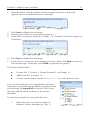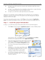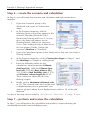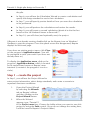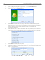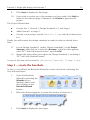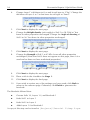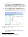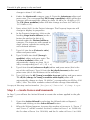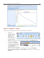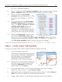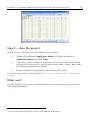
1
Geocentrix
Repute 2
Quick-Start Guide
Onshore pile design and analysis
2
Geocentrix Repute 2 Quick-Start Guide
Notices
Information in this document is subject to change without notice and does not
represent a commitment on the part of Geocentrix Ltd. The software described in
this document is furnished under a licence agreement or non-disclosure agreement
and may be used or copied only in accordance with the terms of that agreement. It
is against the law to copy the software except as specifically allowed in the licence
or non-disclosure agreement. No part of this manual may be reproduced or
transmitted in any form or by any means, electronic or mechanical, including
photocopying and recording, for any purpose, without the express written
permission of Geocentrix Ltd.
©2002-11 Geocentrix Ltd. All rights reserved.
“Geocentrix” and “Repute” are registered trademarks of Geocentrix Ltd. Other
brand or product names are trademarks or registered trademarks of their respective
holders. PGroupN is used under exclusive licence from Geomarc Ltd. PGROUP
code used under licence from TRL Ltd.
Set in Optimum using Corel® WordPerfect® X5. Printed in the UK.
Acknowledgments
Repute 2 was developed with the generous support of Corus, Atkins, and Stent
Foundations.
Repute 2 was designed and written by Dr Andrew Bond of Geocentrix, with the
assistance of Ian Spencer of Honor Oak Systems.
PGroupN was designed and written by Dr Francesco Basile of Geomarc. Special
recognition goes to the late Dr Ken Fleming of Cementation Foundations Skanska
for his invaluable advice and support during the development of PGroupN.
The Repute Quick-Start Guide was written by Andrew Bond.
The following people/organizations assisted with the production of the program
and its documentation: Romain Arnould, Francesco Basile, Jenny Bond, Joe Bond,
Tom Bond, Halcrow Group, and Jack Offord. The following gave generously of
their time during beta testing: Francesco Basile and Dave Rowbottom.
Revision history
Last revised 18 April 2011 (for version 2.0.8).
Table of contents
3
TABLE OF CONTENTS
TABLE OF CONTENTS . . . . . . . . . . . . . . . . . . . . . . . . . . . . . . . . . . . . . . . . . . . . . . 3
INTRODUCING REPUTE 2 . . . . . . . . . . . . . . . . . . . . . . . . . . . . . . . . . . . . . . . . . . .
What’s new in Repute 2?
New geotechnical capabilities
New user interface features
Reporting
Documentation
Quick-start guide (this booklet)
User manual
Reference manual
Help system
Software Re-Assurance™
Notes
6
6
6
6
7
7
7
7
7
8
8
8
TUTORIAL 1
H-PILE IN CLAY AND SAND . . . . . . . . . . . . . . . . . . . . . . . . . . . . . . . . . . . . . . . . . . 9
Overview
9
Step 1 – create the project
10
Step 2 – create the borehole
12
Step 3 – create the pile
14
Step 4 – create the force
16
Step 5 – create the calculations
17
Step 6 – perform and review the calculations
18
Step 7 – produce a report
19
Step 8 – close the project
21
What next?
21
TUTORIAL 2
FLEMING’S HYPERBOLIC ANALYSIS . . . . . . . . . . . . . . . . . . . . . . . . . . . . . . . . . . .
Step 1 – create the project information
Step 2 – create the ground conditions
Step 3 – create the pile
Step 4 – create the force
Step 5 – sleeve the pile
Step 6 – create the scenario and calculation
Step 7 – perform and review the calculation
Step 8 – close the project
What next?
22
23
24
25
26
26
27
27
29
29
4
Geocentrix Repute 2 Quick-Start Guide
TUTORIAL 3
SINGLE PILE DESIGN TO EUROCODE 7 . . . . . . . . . . . . . . . . . . . . . . . . . . . . . . . . .
Overview
Step 1 – create the project
Step 2 – create the borehole
Step 3 – add a water table
Step 4 – create the pile
Step 5 – create the forces
Step 6 – create the calculation
Step 7 – customize the calculation
Step 8 – perform and review the calculations
Step 9 – change the design standard
What next?
TUTORIAL 4
PILE GROUP IN CLAY AND SAND
30
30
31
33
35
35
37
38
39
41
42
44
.....................................
Overview
Step 2 – create the pile group
Step 3 – create the borehole
Step 4 – enter the soils’ stiffness properties
Step 5 – create forces and moments
Step 6 – create the calculation
Step 7 – perform and review the calculation
Step 8 – produce a report
Step 9 – close the project
What next?
45
45
47
48
50
51
53
54
55
56
56
TUTORIAL 5
NON-LINEAR ANALYSIS OF PILE GROUP IN STIFF CLAY OVERLYING ROCK . . . . . . . . .
Overview
Step 1 – create the project
Step 2 – create the pile group
Step 3 – create the soil
Step 4 – create a layer and borehole
Step 5 – create forces and moments
Step 6 – create the calculation
Step 7 – perform and review the calculation
Step 8 – export the results
Step 9 – close the project
What next?
57
58
58
59
62
63
64
65
65
66
67
67
Table of contents
TUTORIAL 6
ASYMMETRIC PILE GROUP UNDER 3D LOADING . . . . . . . . . . . . . . . . . . . . . . . . .
Overview
Step 1 – open and modify an existing project
Step 2 – specify a new pile group
Step 3 – move the piles to their final positions
Step 4 – modify the loads
Step 6 – close the project
What next?
5
68
69
69
70
73
74
77
77
6
Geocentrix Repute 2 Quick-Start Guide
INTRODUCING REPUTE 2
Repute® 2 provides a rich set of capabilities for engineers to design/analyse:
!
various types of single pile, using current and historical design standards
(such as Eurocode 7 and BS 8004)
!
pile groups under generalized 3-dimensional loading, using linear of nonlinear soil models
Repute considers single pile response using a variety of calculation methods for
ultimate and serviceability limit states. Both traditional lumped factors-of-safety and
modern partial factors can be applied in these calculations.
Repute considers pile group behaviour using the boundary element method,
employing the leading analytical program PGroupN (developed by and included
under exclusive licence from Geomarc). PGroupN provides a complete 3D
non-linear boundary element solution of the soil continuum, which overcomes
limitations of traditional interaction-factor methods and gives more realistic
predictions of deformations and the load distribution between piles.
What’s new in Repute 2?
New geotechnical capabilities
!
Verification of vertical load-bearing capacity of single piles
!
Calculation of vertical settlement of single pile
!
Estimation of load-settlement characteristics
!
Full support for design to Eurocode 7 and traditional working stress
design standards
!
Pile group analysis extended to include response to torque
!
Wide range of algorithms allow customization of pre-defined calculations
New user interface features
!
New Re/x Design Studio, with a rich interface for both the simplest and
most complicated of tasks
!
Drawing Board provides plan, elevation, and cross-section views of your
project
!
Property Inspector allows ’live’ editing of any object in the project
Introducing Repute 2
7
!
Project Manager allows quick access to individual components of the
project
!
Stockyard contains over 100 predefined items for use in your project
!
Wide selection of wizards to guide you through commonly performed
procedures
!
Workbook provides a spreadsheet-like display of all results
!
Graph Paper gives a highly customizable visual display of results
!
Message Board records program activities and displays warning and error
messages as appropriate
Reporting
!
Greatly improved reporting capabilities
!
Individual reports may be fully customized in some editions of the
program
Plus, a completely revised and updated Online Help and new Quick-start Guide.
Documentation
Repute 2 is supplied with a detailed Quick-start Guide, comprehensive User
Manual, and authoritative Reference Manual. The latest versions of these manuals
(including any corrections and/or additions since the program’s first release) are
available in electronic (Adobe® Acrobat®) format from the Geocentrix website.
(www.geocentrix.co.uk/repute and follow links to Repute’s documentation).
Quick-start guide (this booklet)
The Repute Quick-start Guide includes six tutorials that show you how to use the
main features of Repute. Each tutorial provides step-by-step instructions on how to
drive the program. There are three tutorials dealing with single pile design and
three with pile group design. The tutorials increase in difficulty and are designed to
be followed in order.
User manual
The Repute User Manual explains how to use Repute. It provides a detailed
description of the program’s user interface, which is being rolled out across all of
Geocentrix’s software applications.
Reference manual
The Repute Reference Manual gives detailed information about the engineering
8
Geocentrix Repute 2 Quick-Start Guide
theory that underpins Repute’s calculations. The manual assumes you have a
working knowledge of the geotechnical design of single piles and pile groups, but
provides appropriate references for further study if you do not.
Help system
Repute’s help system contains detailed information about the program, including
most of the information contained in the Repute Quick-Start Guide, User Manual,
and Reference Manual – plus additional information regarding Repute that is not
found in any of these documents.
Help appears in a separate window to Repute, allowing you to view the help topics
while you continue to work with Repute itself. To open the help system:
!
Press F1
!
Click the Help button in any dialog box
!
Click on the Help button on the right hand side of Repute’s Ribbon
Software Re-Assurance™
Software Re-Assurance (which includes maintenance updates, version upgrades,
and technical support) for Repute is available direct from Geocentrix or through
your local distributor. To obtain Re-Assurance, please contact Geocentrix as
follows:
Repute Technical Support
Geocentrix Ltd
Scenic House, 54 Wilmot Way
Banstead, Surrey
SM7 2PY, United Kingdom
Please quote your licence number on
all correspondence
Voice: +44 (0)1737 373963
Fax: +44 (0)1737 373980
E-mail: [email protected]
Web: www.geocentrix.co.uk/support
Please be at your computer and have
your licence number ready when you
call
Maintenance updates are available free-of-charge from the Geocentrix website.
Notes
The screenshots in this guide were produced on Windows XP. Your screen may
differ, depending on the version of Windows on which you run Repute. Not all
options are available in every edition of Repute.
In this guide, ‘[Projects]’ refers to the folder where your Repute projects are
saved, typically C:\Program Files\Geocentrix\Repute 2\Projects.
Tutorial 1: H-pile in clay and sand
9
TUTORIAL 1
H-PILE IN CLAY AND SAND
This tutorial demonstrates the basic features of Repute, through a worked example
involving the analysis of a single H-pile installed in clay and sand:
!
Ground conditions comprise 5m of clay overlying 20m of dense sand.
3
The clay has unit weight of 20.5 kN/m , angle of shearing resistance of
23E, and undrained shear strength of 60 kPa. The sand has unit weight of
3
18 kN/m and angle of shearing resistance of 35E.
!
The foundation comprises a 305 x 305 x 110 H-pile of steel grade
Advance 275.
!
A vertical load of 700 kN is to be applied to the pile.
!
You want to determine the minimum length of pile needed to safely carry
the applied action according to traditional UK practice.
This tutorial is written for users of the Standard, Enterprise, and Trial Editions of
Repute 2 only. Users of the Professional Edition should look at Tutorials 4-6.
Overview
!
In Step 1, you will use the Project Wizard to enter project information,
select a design standard, and create scenarios to represent short- and
long-term conditions.
!
In Step 2, you will use the Borehole Wizard to create a borehole
containing the clay and sand layers.
!
In Step 3, you will create an H-pile and specify its cross-section and steel
grade.
!
In Step 4, you will create the force applied to the pile.
!
In Step 5, you will use the Calculation Wizard to create the calculations
you want Repute to perform.
!
In Step 6, you will perform the calculations and review the results.
!
In Step 7, you will produce a report summarising the results of the
calculations.
!
In Step 8, you will close (and optionally save) the project.
If Repute is not already running, double-click on the Repute icon on Windows’
Desktop to start the program. Once the splash screen has disappeared, Repute
displays its Welcome page.
10
Geocentrix Repute 2 Quick-Start Guide
If you have an existing project open, click Close
on the program’s Application menu. (You will
be prompted to save your work if you have not
already done so.)
To display the Application menu, click on the
program’s Application button, which is located
in the top-left hand corner of Repute’s user
interface (it contains the program’s icon in a
circle).
Step 1 – create the project
In Step 1, you will use the Project Wizard to enter project information, select a
design standard, and create scenarios to represent short- and long-term conditions.
1
2
3
4
5
Open the Project Wizard by
selecting the Wizards tab on
Repute’s ribbon and then
clicking on the Project Wizard
button.
When the Wizard appears, type
“Tutorial 1” in the Project name
box. Choose the folder where you want to save this project by using the Path
control. (If you do not change the setting here, it will be saved in Repute’s
Projects folder.)
Enter “H-pile in clay and sand” in the Description box.
Enter “0001” in the Project ID box.
Click Next to display the next page. The design standards that appear here
depend on which edition of Repute you are running (the Enterprise Edition
supports more design standards than the Standard and Professional editions).
Tutorial 1: H-pile in clay and sand
11
6
Select BS 8004: 1986 by clicking on the relevant checkbox (a tick mark
appears next to a standard when it is selected).
7
8
9
Click Next to display the next page.
Increase the number of construction stages to 2.
In the table, change the longevity of Stage 1 to “Transient” but leave Stage 2 as
“Persistent”.
10 Click Next to display the final page.
11 If you wish to review any of the settings you have made, click Back to return to
the relevant page. Otherwise, click Finish to generate the project.
The Project Wizard then:
!
Creates Site 1, Ground 1, Design Standard 1, and Stages 1-2
!
Adds Ground 1 to Stages 1-2
!
Creates a new project named Tutorial 1.rpx with all these items
You can view these items by right-clicking anywhere
inside the Project Manager to display its context menu
and selecting the Expand All command. The Project
Manager will then look as shown in the picture
alongside.
To view the properties of any particular item:
1.
Select the item you want to inspect in
Repute’s Project Manager (e.g. Site 1)
12
Geocentrix Repute 2 Quick-Start Guide
2.
Display the Property Inspector for that item by:
!
!
3.
Right-clicking on the item, to display its context menu, and clicking
the Properties... command
Or ... Double-clicking on the item
Repute’s Property Inspector will open and
display the properties of the selected item.
(For example, for Site 1 the description is
shown as “H-pile in clay and sand” and the
Project ID as “0001”.)
A copy of this step can be found at
[Projects]\Tutorial 1\Step 1.rpx.
Step 2 – create the borehole
In Step 2, you will use the Borehole Wizard to create a borehole containing the
clay and sand layers.
1.
Open the Borehole
Wizard by selecting the
Wizards tab on
Repute’s ribbon and
then clicking on the
Borehole Wizard
button.
2.
When the Wizard appears, increase the number of layers to 2.
3.
Click Next to display the next page.
4.
Change Layer 1's thickness to 5m and its soil type to “Clay”. Change the
thickness of Layer 2 to 20m but leave its soil type as “Sand”.
5.
Click Next to display the next page.
Tutorial 1: H-pile in clay and sand
6.
13
3
Change the Weight density (unit weight) of Soil 1 to 20.5 kN/m and its
Angle of shearing to 23E. Change the weight density of Soil 2 to
3
18 kN/m and its angle of shearing to 35E. Leave the Cohesion of both
soils unchanged.
7.
Click Next to display the next page.
8.
Change the Strength of Soil 1 to 60 kPa. Leave all other properties
unchanged. (Note that Soil 2 does not appear on this page, since it is a
sand and so does not have undrained properties.)
9.
Click Next to display the next page.
10.
Click All to select both scenarios.
11.
Click Next to display the final page.
12.
If you wish to review any of the settings you have
made, click Back to return to the relevant page.
Otherwise, click Finish to generate the borehole.
The Borehole Wizard then:
!
Creates Soils 1-2, Layers 1-2, and Borehole 1
!
Links Soil 1 to Layer 1
!
Links Soil 2 to Layer 2
!
Adds Layers 1-2 to Borehole 1
A copy of this step can be found at [Projects]\Tutorial 1\Step 2.rpx.
14
Geocentrix Repute 2 Quick-Start Guide
Step 3 – create the pile
In Step 3, you will create an H-pile and specify its cross-section and steel grade.
1.
Open the
Stockyard
by selecting
the View
tab on
Repute’s
ribbon and
then clicking on the Construct button.
2.
When the program has switched to its
Construction Desktop (in which the
Drawing Board, Project Manager, and
Stockyard are displayed), right-click
anywhere inside the Stockyard to display
its context menu and select the Bearing
Piles command. The Bearing Piles group
will open.
3.
Create the section by selecting the item
labelled “UKBP 305x305x95”, rightclicking to display its context menu, and
then selecting the command Create
‘UKBP 305x305x95’.
4.
The newly-created hot-rolled section will
appear in the Project Manager (under
Sections).
5.
Next, right-click anywhere inside the Stockyard to display its context
menu and select the Steels command. The Steels group will open.
6.
Create the steel by holding the Ctrl key down and clicking on the item
labelled “Advance 275”. (When the Ctrl key is pressed, Repute
automatically creates any item that you select in the Stockyard. This saves
you the effort of displaying the popup menu each time you want to
create a new item.)
7.
The newly-created steel will appear in the
Project Manager (under Materials).
8.
Finally, click on the Stockyard’s Structural
Elements caption (near the bottom of the
Stockyard). The Structural Elements panel
will open.
Tutorial 1: H-pile in clay and sand
15
9.
Create the pile by holding the Ctrl key down and clicking on the item
labelled “H-pile”.
10.
The newly-created pile will appear in the
Project Manager (under Structural Elements).
11.
In the Project Manager, right-click on the
newly-created pile (“Pile 1”) to display its
context menu and select the Properties...
command. The Property Inspector will
appear.
12.
In the Property Inspector, change the
Material Name (under Material Properties)
from “Not specified” to “Steel 1”. Then change the Section Name (under
Section Properties) from “Not specified” to “Section 1”. Leave all other
properties of the pile unchanged.
13.
Returning to the Project Manager, select
Stage 1 (under Scenarios).
14.
In the Property Inspector, place a tick next
to Pile 1 (under Structural Elements) and
press Enter to add the pile to this
scenario. The Drawing Board will refresh.
15.
Repeat the previous instruction for Stage
2.
In this step, you have:
!
Created Section 1, Steel 1, and Pile 1
!
Linked Section 1 and Steel 1 to Pile 1
!
Added Pile 1 to Stages 1 and 2
The Drawing Board will now look something like this:
A copy of this step can be found at [Projects]\Tutorial 1\Step 3.rpx.
16
Geocentrix Repute 2 Quick-Start Guide
Step 4 – create the force
In Step 4, you will create the force applied to the pile.
1.
Open the
Stockyard’s
Actions panel by
selecting the
Insert tab on
Repute’s ribbon
and then clicking
on the Action button.
2.
The Actions group will open in the Stockyard.
3.
Hold the Ctrl key down and click on the item
labelled “Force”.
4.
The newly-created force will appear in the
Project Manager (under Actions).
5.
In the Property Inspector, change the
Variability of Force 1 (under General) to
“Permanent” and the value for Fz (under
Action) to 700 kN and press Enter. The
Resultant will automatically change to 700
kN.
6.
In the Project Manager, select “Stage 1”
(under Scenarios).
7.
In the Property Inspector, place a tick next
to Force 1 (under Actions) and press Enter to add the action to this
scenario. The Drawing Board will refresh and now look like this:
8.
Repeat the previous instruction for Stage 2.
Tutorial 1: H-pile in clay and sand
17
In this step, you have:
!
Created Force 1
!
Added Force 1 to Stages 1 and 2
A copy of this step can be found at [R]\Projects\Tutorial 1\Step
4.rpx.
Step 5 – create the calculations
In Step 5, you will use the Calculation Wizard to create the calculations you want
Repute to perform.
1.
Open the Calculation Wizard by selecting the Wizards tab on Repute’s
ribbon and then clicking on the Calculation Wizard button.
2.
When the Wizard appears, select “Longitudinal ULS”. (The calculations
that appear here depend on which edition of Repute you are running.
The Enterprise Edition provides more calculations than the Standard and
Professional editions.)
3.
Click Next to display the next page.
4.
Select “Design Standard 1” (this is the BS 8004 design standard created
in Step 1 of this tutorial).
5.
Click Next to display the next page.
6.
Click All to select both scenarios.
7.
Click Next to display the final page.
8.
If you wish to review any of the settings you have made, click Back to
return to the relevant page. Otherwise, click Finish to generate the
calculations.
The Calculation Wizard then:
18
Geocentrix Repute 2 Quick-Start Guide
!
Creates Calculations 1-2
!
Links Stage 1 to Calculation 1
!
Links Stage 2 to Calculation 2
!
Links Design Standard 1 to Calculations 1-2
A copy of this step can be found at [Projects]\Tutorial 1\Step 5.rpx.
Step 6 – perform and review the calculations
In Step 6, you will perform the calculations and review the results.
1.
Run the
calculation by
selecting the
Build tab on
Repute’s ribbon
and then clicking
on the Run All
button.
2.
Repute will perform all the calculations that you have
specified (i.e. Calculations 1 and 2) and then change to its
Checking Desktop (which displays the Workbook, Graph
Paper). You can switch to this display at any time by
clicking on the Check button on the View tab of Repute’s
ribbon.
3.
Your screen will now look something like this:
Tutorial 1: H-pile in clay and sand
4.
19
The Graph Paper (top right panel) shows:
!
!
!
the effect of the actions E (equal to the sum of the applied forces
and the self-weight of the pile) increasing with depth
the separate components of shaft and base resistances, Rs and Rb,
also increasing with depth
the total compressive resistance, Rc = Rs + Rb, exceeding the effect
of actions (E # Rc) at a depth of about 15.15 m
5.
The Workbook (top left panel) shows the
same information, but in tabular format.
The Workbook contains a lot more
information than is initially shown. To
display this additional information, click on
the button labelled ‘*’ in the top-left-hand
corner of the Workbook (to the left of the
heading ‘Depth’) and select the data you
want to see.
6.
To view the results of the first calculation,
select Calculation 1 in the Project
Manager. Repute will automatically update
the Workbook and Graph Paper with this calculation’s data. (To display
the Project Manager, selecting the View tab on Repute’s ribbon and then
click on the Project Manager button.)
Step 7 – produce a report
In Step 7, you will produce a report summarising the calculations.
1.
Display Repute’s reporting
tools by selecting the View
tab on Repute’s ribbon
and then clicking on the
Review button.
2.
Next, create a report by
selecting the Reporter tab
on Repute’s ribbon and clicking on the
Refresh button.
3.
Repute will generate the requested report
and display it, together with a set of
thumbnails, in the Reporter.
20
1
Geocentrix Repute 2 Quick-Start Guide
4.
You can navigate
around the report
using the controls on
the Reporter tab on
Repute’s ribbon: First
Page, Previous Page, Next Page, and Last Page. You can jump to specific
pages by clicking on the thumbnails on the left-hand side of the Reporter.
5.
You can also re-size the report using the Fit Width, Fit Height, Zoom In,
and Zoom Out controls.
6.
You can choose what to
include in your report by
selecting or deselecting
individual items in the Report
Elements group, then clicking
the Refresh button.
7.
You can edit the report’s layout using the Modify
command (this is only available in the Enterprise Edition of
the program).
8.
Finally, you can output the report onto paper using the
Print command and choosing from the options provided in the dialog
1
box that appears on your screen.
You cannot print the project in the Trial Edition of Repute
Tutorial 1: H-pile in clay and sand
21
Step 8 – close the project
2
In Step 8, you will close and (optionally) save the project.
1.
Display the program’s Application Menu by clicking on Repute’s
Application Button.
2.
When the menu appears, close the project by clicking on the Close
command.
3.
If you have made changes to the project since it was last saved, Repute
will ask you if you want to save before proceeding. Answer Yes or No by
clicking the appropriate button.
4.
Repute will then (if requested) save and close the project.
A copy of this project can be found at [Projects]\Tutorial 1\Tutorial
1.rpx.
What next?
Tutorial 2 shows you how to set up Fleming’s hyperbolic analysis.
2
You cannot save the project in the Trial Edition of Repute
22
Geocentrix Repute 2 Quick-Start Guide
TUTORIAL 2
FLEMING’S HYPERBOLIC ANALYSIS
Tutorial 2 shows you how to construct a load vs displacement curve for a single
pile, using Fleming’s hyperbolic analysis, described in his 1992 Géotechnique paper
“A new method for single pile settlement prediction and analysis” (see vol. 42, no.
3, pp 411-425). This tutorial demonstrates how to setup a calculation in Repute
without using the program’s built-in wizards, thereby showing you how versatile the
program’s user interface is.
The worked example is taken from Figure 6 in Fleming’s paper (referenced above),
which is based upon from tests carried out at Wembley by Whitaker & Cooke. We
are interested in replicating the load vs displacement curve given by Fleming’s
analysis.
!
Ground conditions at the site are not given in the paper, so we will
assume 25m of London Clay with an undrained strength of 100 kPa and
an angle of shearing resistance of 23E.
!
The pile studied is a 12.2 m long, 775 mm diameter bored pile made of
concrete with Young’s modulus equal to 19.5 GPa.
!
A vertical load of 200 tonnes (approximately 2000 kN) is applied at the
centre of the pile.
!
The ultimate load that the pile can carry has been calculated (separately)
as 1994 kN on the shaft and 1002 kN from the base. The soil modulus
below the pile base is 33.125 MPa. Other parameters used by Fleming
are the shaft flexibility factor (0.0017 or 0.17%) and effective column
length factor (0.45).
This tutorial is written for users of the Standard, Enterprise, and Trial Editions of
Repute 2 only. Users of the Professional Edition should look at Tutorials 4-6.
Overview
!
In Step 1, you will enter project information about the site and the
Engineer.
!
In Step 2, you will define the site’s ground conditions.
!
In Step 3, you will create a bored pile and specify its cross-section and
concrete grade.
!
In Step 4, you will create the force applied to the pile.
!
In Step 5, you will sleeve the pile through the made ground.
Tutorial 2: Fleming’s hyperbolic analysis
23
!
In Step 6, you will create the scenario and calculation and link various
items together.
!
In Step 7, you will perform the calculation and produce a report showing
the relationship between load and displacement.
!
In Step 8, you will close (and optionally save) the project.
If Repute is not already running, double-click on the Repute icon on Windows’
Desktop to start the program. Once the splash screen has disappeared, Repute
displays its Welcome page.
If you have an existing project open, click Close on the program’s Application
menu. You will be prompted to save your work if you have not already done so.
Step 1 – create the project information
In Step 1, you will enter project information about the site and the Engineer.
1.
Click New on the program’s Application menu to create a blank project.
Alternatively, click on the New button on the Quick-access toolbar,
located on the right-hand side of the Application Button.
2.
Open the Stockyard’s Project Information group by
selecting the Insert tab on Repute’s ribbon and
then clicking on the Project Information button.
3.
The Project Information group will open in the
Stockyard.
4.
Hold the Ctrl key down and click on the
item labelled “Construction Site”. A newlycreated site will appear in the Project
Manager (under Project Information).
5.
In the Project Manager, double-click on
the newly-created site (“Site 1”) to open its
Property Inspector.
24
Geocentrix Repute 2 Quick-Start Guide
6.
In the Property Inspector, change the Name to “Wembley”.
7.
Enter “Fleming’s Hyperbolic Analysis” in the Description box and click
OK to confirm what you have typed.
8.
Enter “Fig. 6” in the Project ID box.
9.
Returning to the Stockyard, create a Party by holding down the Ctrl key
and clicking on the item labelled “Party”. A newly-created party will
appear in the Project Manager (under Project Information) as “Party 1”
and the Property Inspector will display its default properties.
10.
In the Property Inspector, change the Name of the newly-created party to
“Whitaker and Cooke” and their role to “Engineer” (if not already
selected).
A copy of this step can be found at [Projects]\Tutorial 2\Step 1.rpx.
Step 2 – create the ground conditions
In Step 2, you will define the site’s ground
conditions.
1.
Returning to the Stockyard, click on the
button labelled Common to open the
Common group, where you will find
(amongst other items) Plane Ground.
2.
Hold the Ctrl key down and click on the
item labelled “Plane Ground” to create it.
3.
In the Property Inspector, change the
Name of the Plane Ground to “Horizontal
Ground” but leave its other (default)
properties unchanged.
4.
Back in the Stockyard, open the Materials
group so that you can create a Clay. You
may need to click one of the small buttons
at the bottom of the Stockyard to display
this group. You can move the mouse over
each button in turn to display a tooltip
indicating which panels they control.
Create the Clay by Ctrl-clicking on it.
5.
In the Property Inspector, change the
Name of the new Clay to “London Clay”,
and enter the following properties: under
Drained Strength, angle of shearing
resistance 23E; under Undrained Strength,
Tutorial 2: Fleming’s hyperbolic analysis
25
minimum undrained strength 100 kPa. The maximum undrained strength
will automatically change to 100 kPa also.
6.
In the Stockyard, open the Geotechnical Constituents group and create
both a Soil Layer and a Borehole.
7.
Select the layer in the Project Manager and then (in the Property
Inspector) change its Name to “Clay Layer”, its Thickness to 25m, and
select “London Clay” in its Soil box.
8.
Now select the borehole in the Project Manager and then (in the
Property Inspector) rename it “Wembley Borehole” and, under Layers >
Next, select “Clay Layer”.
A copy of this step can be found at [Projects]\Tutorial 2\Step 2.rpx.
Step 3 – create the pile
In Step 3, you will create a bored pile and specify its cross-section and concrete
grade.
1.
Open the Concretes group in the
Stockyard and create a concrete of grade
C35/45.
2.
In the Property Inspector, attempt to
change the Young’s modulus (E) of the
new concrete to 19.5 GPa.
3.
When you press enter, the value will revert back to 34 GPa and the
Message Board will open to reveal the error message “Young’s modulus
must be >= 27 GPa and <= 44 GPa. Value entered = 19.5 GPa”. You can
see this message more easily if you click on the Errors tab at the top of
the Message Board.
4.
Since the value of Young’s modulus used by Fleming is outside of the
allowable range for Grade Concrete, we will use Custom Concrete
instead.
5.
Back in the Concretes panel, create a Custom Concrete. Then set its
Young’s modulus to 19.5 GPa as described in item 2 above. (This should
succeed.)
6.
Because we no longer need the Grade Concrete, we can delete it from
26
Geocentrix Repute 2 Quick-Start Guide
the project by right-clicking on ‘Concrete 1’ in the Project Manager and
selecting Edit > Delete. When prompted, confirm that you want to delete
‘Concrete 1’.
7.
Open the Structural Elements group in the Stockyard and create a Bored
Pile.
8.
In the Property Inspector, change the Length of the new pile to 12.2 m
and its Shaft diameter to 775 mm. The base diameter will automatically
increase to 775 mm (displayed as 0.78 m). Finally, select “Concrete 2” in
the box Material name.
A copy of this step can be found at [Projects]\Tutorial 2\Step 3.rpx.
Step 4 – create the force
In Step 4, you will create the force applied to the pile.
1.
Open the Actions group in the Stockyard
and create a Force.
2.
In the Property Inspector, change the
Variability of the new force to
“Permanent” and its Fz component to
2000 kN. The resultant will automatically
change to 2000 kN.
A copy of this step can be found at
[Projects]\Tutorial 2\Step 4.rpx.
Step 5 – sleeve the pile
In Step 5, you will sleeve the pile through the made ground.
1.
Open the Algorithms group in the
Stockyard and create a Shrinkagealgorithm.
2.
In the Property Inspector, change the
Name of the new algorithm to “Length in
made ground” and its Shrinkage depth to
1.4m. The Algorithm Option will
automatically change to “Custom
shrinkage”. This tells the calculation to
ignore the top 1.4m of the pile shaft when calculating skin friction.
A copy of this step can be found at [Projects]\Tutorial 2\Step 5.rpx.
Tutorial 2: Fleming’s hyperbolic analysis
27
Step 6 – create the scenario and calculation
In Step 6, you will create the scenario and calculation and link various items
together.
1.
Open the Scenarios group in the
Stockyard and create a Construction
Stage.
2.
In the Property Inspector, tick the
following items so that they appear in this
scenario: Wembley Borehole, Pile 1,
Horizontal Ground, and Force 1. As you
do so, the items will appear on the
Drawing Board. (Make sure you press
Enter after ticking the last of these items,
for it to appear.) Finally, change the
scenario’s Situation to “Transient”.
3.
Open the Calculations group in the Stockyard so that you can create a
Fleming Analysis.
4.
In the Property Inspector, set the Construction Stage to “Stage 1” and
the Shrinkage to “Length in made ground”.
5.
Enter the following values for the
calculation’s other properties: Ultimate
shaft load (Us) 1994 kN; Ultimate base
load (Ub) 1002 kN; Base stiffness (Eb)
33.125 MPa; Shaft flexibility (Ms) 0.17%;
and Effective column length (Ke) 0.45.
These values are taken directly from
Fleming’s paper.
6.
Finally, set the Maximum settlement ratio
to 1%. This controls how much of the load
vs displacement curve is generated. You
want to go up to about 8 mm displacement, which is 1% of the pile
diameter.
A copy of this step can be found at [Projects]\Tutorial 2\Step 6.rpx.
Step 7 – perform and review the calculation
In Step 7, you will perform the calculation and produce a report showing the
relationship between load and displacement.
28
Geocentrix Repute 2 Quick-Start Guide
1.
Run the calculation by selecting the
Build tab on Repute’s ribbon and
then clicking on the button labelled
Run ‘Stage 1’.
2.
Repute performs all the calculations
that are linked to Stage 1 and then
changes to its Checking Desktop
(which displays the Workbook, and Graph Paper).
3.
Your screen will now look something like this:
4.
The Graph Paper (centre) displays a graph which is almost identical to
Figure 6 in Fleming’s paper, showing:
!
!
!
5.
Base load vs displacement (in blue)
Shaft load vs displacement (in pink)
Total load vs displacement (in green)
You can view the data on which this graph is based in the Workbook
(left).
Tutorial 2: Fleming’s hyperbolic analysis
29
Step 8 – close the project
3
In Step 8, you will close and (optionally) save the project.
1.
Display the program’s Application Menu by clicking on Repute’s
Application Button and click Close.
2.
If you have made changes to the project since it was last saved, Repute
will ask you if you want to save it before proceeding. Answer Yes or No
by clicking the appropriate button.
3.
Repute will then (if requested) save and close the project.
A copy of this project can be found at [Projects]\Tutorial 2\Tutorial
2.rpx.
A Repute project which reproduces all nine hyperbolic analyses from of Fleming’s
paper can be found in [Projects]\Examples\Fleming (1992).rpx.
What next?
Tutorial 3 shows you how to design a single pile in accordance with the
requirements of Eurocode 7.
3
You cannot save the project in the Trial Edition of Repute
30
Geocentrix Repute 2 Quick-Start Guide
TUTORIAL 3
SINGLE PILE DESIGN TO EUROCODE 7
Tutorial 3 shows you how to design a single pile according to the requirements of
Eurocode 7. The worked example is taken from Chapter 13 of the book “Decoding
Eurocode 7” by Bond and Harris (2008), London: Taylor and Francis.
!
Ground conditions comprise 8 m of medium strength sandy CLAY
overlying medium dense gravelly SAND. The clay has characteristic
undrained strength of 45 kPa and characteristic weight density of 18.5
3
kN/m . The sand a characteristic angle of shearing resistance of 36E, zero
3
effective cohesion, and characteristic weight density of 20 kN/m . The
sand’s constant-volume angle of shearing-resistance is 33E.
!
Groundwater at the site is at 1 m depth and skin friction above
groundwater will be ignored.
!
The pile studied is a 10 m long, 400 mm square pile made of concrete
3
with characteristic weight density of 25 kN/m .
!
Vertical loads of 650 kN (permanent) and 250 kN (variable) will be
applied to the pile.
!
You want to determine the minimum pile length required by Eurocode 7
according to the National Annexes published in Ireland and in the United
Kingdom.
Full hand calculations for this example are given as Examples 13.1 and 13.2 in Bond
and Harris (2008).
This tutorial is written for users of the Standard, Enterprise, and Trial Editions of
Repute 2 only. Users of the Professional Edition should look at Tutorials 4-6.
Overview
!
In Step 1, you will use the Project Wizard to enter project information,
select design standards, and create a scenario to represent short-term
conditions.
!
In Step 2, you will use the Borehole Wizard to create a borehole
containing the clay and sand layers.
!
In Step 3, you will add a water table to the scenario.
!
In Step 4, you will create a pile and specify its cross-section and concrete
grade.
!
In Step 5, you will use the Action Wizard to create the forces applied to
Tutorial 3: Single pile design to Eurocode 7
31
the pile.
!
In Step 6, you will use the Calculation Wizard to create a calculation and
specify the design standard to use in that calculation.
!
In Step 7, you will specify precise details of how you want the calculation
to be performed.
!
In Step 8, you will perform the calculations and review the results.
!
In Step 9, you will create a second calculation, identical to the first but
based on the UK National Annex to Eurocode 7.
!
In Step 10, you will close (and optionally save) the project.
If Repute is not already running, double-click on the Repute icon on Windows’
Desktop to start the program. Once the splash screen has disappeared, Repute
displays its Welcome page.
If you have an existing project open, click Close
on the program’s Application menu. (You will
be prompted to save your work if you have not
already done so.)
To display the Application menu, click on the
program’s Application button, which is located
in the top-left hand corner of Repute’s user
interface (it contain’s the program’s icon in a
circle).
Step 1 – create the project
In Step 1, you will use the Project Wizard to
enter project information, select design standards, and create a scenario to
represent short-term conditions.
1.
Open the Project Wizard
by selecting the Wizards
tab on Repute’s ribbon
and then clicking on the
Project Wizard button.
2.
When the Wizard
appears, type “Tutorial 3“
in the Project name box. Choose the folder where you want to save this
project by using the Path control. (If you do not change the setting here,
it will be saved in Repute’s Projects folder.)
32
Geocentrix Repute 2 Quick-Start Guide
3.
Enter “Single pile design to Eurocode 7” in the Description box.
4.
Enter “0003” in the Project ID box.
5.
Click Next to display the next page. The design standards that appear
here depend on which edition of Repute you are running (the Enterprise
Edition supports more design standards than the Standard and
Professional editions).
6.
Select BS EN 1997-1: 2007 and IS EN 1997-1 by clicking on the relevant
check-boxes (a tick mark appears next to a standard when it is selected).
7.
Click Next to display the next page.
8.
Keep the number of construction stages as 1, but change the longevity of
Stage 1 to “Transient”.
Tutorial 3: Single pile design to Eurocode 7
9.
Click Next to display the final page.
10.
If you wish to review any of the settings you have made, click Back to
return to the relevant page. Otherwise, click Finish to generate the
project.
33
The Project Wizard then:
!
Creates Site 1, Ground 1, Design Standards 1-2, and Stage 1
!
Adds Ground 1 to Stage 1
!
Creates a new project named Tutorial 3.rpx with all of these items
in it
Finally, you will rename the design standards to make it easier to identify them
later.
11.
Locate Design Standard 1 (under “Design Standards”) in the Project
Manager, right-click on it and select Rename. In the box that appears,
enter “EC7 with UK National Annex” and click OK.
12.
Repeat the instructions given above for Design Standard 2, renaming it
“EC7 with Irish National Annex”.
A copy of this step can be found at [Projects]\Tutorial 3\Step 1.rpx.
Step 2 – create the borehole
In Step 2, you will use the Borehole Wizard to create a borehole containing the
clay and sand layers.
1.
Open the Borehole
Wizard by selecting the
Wizards tab on
Repute’s ribbon and
then clicking on the
Borehole Wizard
button.
2.
When the Wizard appears, increase the number of layers to 2.
3.
Click Next to display the next page.
34
Geocentrix Repute 2 Quick-Start Guide
4.
Change Layer 1’s thickness to 8 m and its soil type to “Clay”. Change the
thickness of Layer 2 to 5 m but leave its soil type as “Sand”.
5.
Click Next to display the next page.
6.
Change the Weight density (unit weight) of Soil 1 to 18.5 kN/m but
leave its other properties unchanged. Change the Angle of shearing of
Soil 2 to 36E but leave its other properties unchanged.
7.
Click Next to display the next page.
8.
Change the Strength of Soil 1 to 45 kPa. Leave all other properties
unchanged. (Note that Soil 2 does not appear on this page, since it is a
sand and so does not have undrained properties.)
3
9.
Click Next to display the next page.
10.
Place a tick in the checkbox for Stage 1.
11.
Click Next to display the final page.
12.
If you wish to review any of the settings you have made, click Back to
return to the relevant page. Otherwise, click Finish to generate the
borehole.
The Borehole Wizard then:
!
Creates Soils 1-2, Layers 1-2, and Borehole 1
!
Links Soil 1 to Layer 1
!
Links Soil 2 to Layer 2
!
Adds Layers 1-2 to Borehole 1
A copy of this step can be found at [Projects]\Tutorial 3\Step 2.rpx.
Tutorial 3: Single pile design to Eurocode 7
35
Step 3 – add a water table
In Step 3, you will add a water table to the scenario.
1.
Open the Stockyard’s
Geotechnical Constituents
panel by selecting the Insert
tab on Repute’s ribbon and
then clicking on the
Geotechnical Constituents
button.
2.
The Geotechnical Constituents panel will open in the Stockyard.
3.
Hold the Ctrl key down and click on the item labelled “Ground Water
Table”.
4.
The newly-created water table will appear in the Project Manager (under
Geotechnical Constituents).
5.
In the Property Inspector, change the Depth (under Dimensions) of
Water Table 1 to 1 m.
6.
In the Project Manager, select “Stage 1” (under Scenarios).
7.
In the Property Inspector, place a tick next to Water Table 1 (under
Geotechnical Constituents) and press Enter to add the water table to
this scenario. The Drawing Board will refresh.
In this step, you have:
!
Created Water Table 1
!
Added Water Table 1 to Stage 1
You will find a copy of the project in its current state at [Projects]\Tutorial
3\Step 3.rpx.
Step 4 – create the pile
In Step 4, you will create a pile and specify its cross-section and concrete grade.
1.
Open the Stockyard by
selecting the View tab
on Repute’s ribbon and
then clicking on the
Construct button.
36
Geocentrix Repute 2 Quick-Start Guide
2.
When the program has switched to its Construction Desktop (in which
the Drawing Board, Project Manager, and Stockyard are displayed), rightclick anywhere inside the Stockyard to display its context menu and
select the Concretes command. The Concretes group will open.
3.
Create the concrete by holding the Ctrl key down and clicking on the
item labelled “C30/37”. (When the Ctrl key is pressed, Repute
automatically creates any item that you select in the Stockyard.) The
newly-created concrete will appear in the Project Manager (under
Materials).
4.
Next, click on the Stockyard’s Structural Elements caption (near the
bottom of the Stockyard). The Structural Elements group will open.
5.
Create the pile by holding the Ctrl key down and clicking on the item
labelled “Square Pile”.
6.
The newly-created pile will appear in the Project Manager (under
Structural Elements).
7.
In the Project Manager, right-click on the newly-created pile (“Pile 1”) to
display its context menu and select the Properties... command. The
Property Inspector will appear.
8.
In the Property Inspector, change the
Material Name (under Material Properties)
from “Not specified” to “Concrete 1”.
Then change the pile’s Length (under
Dimensions) to 10 m and its Breadth
(under Section Properties) to 400 mm.
Leave all other properties of the pile
unchanged.
9.
Returning to the Project Manager, select
Stage 1 (under Scenarios).
10.
In the Property Inspector, place a tick next
to Pile 1 (under Structural Elements) and
press Enter to add the pile to this
scenario. the Drawing Board will refresh.
In this step, you have:
!
Created Concrete 1 and Pile 1
!
Linked Concrete 1 to Pile 1
!
Added Pile 1 to Stage 1
A copy of this step can be found at [Projects]\Tutorial 3\Step 4.rpx.
Tutorial 3: Single pile design to Eurocode 7
37
Step 5 – create the forces
In Step 5, you will use the Action Wizard to create the forces applied to the pile.
1.
Open the Action Wizard by selecting the Wizards tab on Repute’s
ribbon and clicking on the Action Wizard button.
2.
When the Wizard appears, increase the number of forces to 2; “Force 1”
and “Force 2” will be created. Set the Fz value for Force 1 to 650 kN and
change its Variability to “Permanent”. Then set the Fz value for Force 2
to 250 kN but keep its Variability as “Variable”.
3.
Click Next to display the next page.
4.
Since no moments are applied to the pile, leave the number of moments
as 0 and click Next to display the next page.
5.
Increase the number of combinations to 1; “Combination 1” will be
created. Under then column Forces to include..., tick Force 1 and Force
2.
6.
Click Next to display the last page.
7.
If you wish to review any of the settings you have made, click Back to
return to the relevant page. Otherwise, click Finish to generate the
actions and their combination.
8.
Returning to the Project Manager, select Stage 1 (under Scenarios). Then,
in the Property Inspector, place a tick next to Combination 1 (under
Actions) and press Enter to add the combination to this scenario. The
38
Geocentrix Repute 2 Quick-Start Guide
Drawing Board will refresh.
The Actions Wizard has:
!
Created Forces 1-2
!
Created Combination 1
!
Added Forces 1-2 to Combination 1
And you have:
!
Added Combination 1 to Stage 1
A copy of this step can be found at [Projects]\Tutorial 3\Step 5.rpx.
Step 6 – create the calculation
In Step 6, you will use the Calculation Wizard to create a calculation and specify
the design standard to use in that calculation.
1.
Open the Calculation Wizard by selecting the Wizards tab on Repute’s
ribbon and then clicking on the Calculation Wizard button.
2.
When the Wizard appears, select “Longitudinal ULS”. (The calculations
that appear here depend on which edition of Repute you are running.
The Enterprise Edition provides more calculations than the Standard and
Professional editions.)
3.
Click Next to display the next page.
4.
Select “EC7 with Irish National Annex”.
Tutorial 3: Single pile design to Eurocode 7
39
5.
Click Next to display the next page.
6.
Place a tick in the checkbox next to Stage 1.
7.
Click Next to display the final page and then Finish to generate the first
calculation.
The Calculation Wizard then:
!
Creates Calculation 1
!
Links Stage 1 to Calculation 1
!
Links “EC7 with Irish National Annex” to Calculation 1
A copy of this step can be found at [Projects]\Tutorial 3\Step 6.rpx.
Step 7 – customize the calculation
In Step 7, you will specify precise details of how you want the calculation to be
performed. (These choices correspond to the decisions made by Bond and Harris,
2008.)
1.
Open the Stockyard’s Algorithms group
by selecting the Insert tab on Repute’s
ribbon and then clicking on the
Algorithm button.
2.
Hold the CTRL key down and click on
“Shrinkage” in the Stockyard. Then, in
the Property Inspector, change the Name of the new algorithm to “No
skin friction” and enter “Ignore skin friction above water table” in its
Notes field. Change the value of the Shrinkage depth to 1.0 m,
whereupon the Algorithm Option will automatically change to “Custom
shrinkage”.
40
Geocentrix Repute 2 Quick-Start Guide
3.
Hold the CTRL key down and click on
“Alpha” in the Stockyard. Change the
Name of the new algorithm to “Alpha in
clay” and enter “From US Army Corps of
Engineers” in its Notes field. Change the
value of Alpha to 0.8, whereupon the
Option will automatically change to
“Custom alpha”.
4.
Hold the CTRL key down and click on
“Lateral earth pressure coefficient” in the Stockyard. Change the Name of
the new algorithm to “Ks in sand” and enter “= Nq/50” in its Notes field.
Change the value of the Compressive lateral coefficient to 1.59,
whereupon the Option will automatically change to “Custom
coefficient”.
5.
Hold the CTRL key down and click on “Wall friction” in the Stockyard.
Change the Name of the new algorithm to “Delta in sand” and enter “=
constant volume angle of shearing resistance” in its Notes field. Change
the value of Wall friction to 33E, whereupon the Option will
automatically change to “Custom friction”.
6.
Hold the CTRL key down and click on “Bearing capacity algorithm” in
the Stockyard. Change the Name of the new algorithm to “Nq in sand”.
Change the Option to Berezantzev. The values of Nq, Ny, and Nc will
update their values corresponding to the parameters entered into the
Ready Reckoner. Try changing the values in the Angle of shearing
resistance and Slenderness ratio fields to see the effect.
7.
Finally, select “Calculation 1” in the
Project Manager and then, in the Property
Inspector, set a link to the bearing
capacity algorithm you have just created
by clicking on the down arrow to the right
of the heading Bearing Capacity Factor
and selecting ‘Nq in sand’.
8.
Repeat the previous instruction for the
other four algorithms that you have
created (the only link that should not be
set is Beta, which is not used in this
example).
9.
Also tick the Undrained resistance option
to ensure that the calculation is based on
total stresses in the clay.
A copy of this step can be found at [Projects]\Tutorial 3\Step 7.rpx.
Tutorial 3: Single pile design to Eurocode 7
41
Step 8 – perform and review the calculations
In Step 8, you will perform the calculation and review the results.
1.
Run the calculation by selecting the
Build tab on Repute’s ribbon and
then clicking on the Run ‘Stage 1’
button.
2.
Repute will perform the specified
calculation and then change to its
Check Desktop (which displays the
Workbook and Graph Paper). Your screen will now look something like:
3.
The Graph Paper (top right panel) shows the:
!
!
!
4.
Effect of the action (E, equal to the sum of the applied forces and
the self-weight of the pile) increasing with depth
separate components of Base resistance (Rb) and Shaft resistance (Rs)
also increasing with depth
Compressive resistance (Rc = Rs + Rb) exceeding the effect of actions
(E # Rc) at a depth between 11 and 12 m
The Workbook (top left panel) shows the same information, but in
tabular format. The Workbook contains a lot more information than is
42
Geocentrix Repute 2 Quick-Start Guide
initially shown. To display this additional information, click on the button
in the top-left-hand corner (labelled *) and select the data you want to
see. The picture here show results for the depth 10 m.
5.
The results calculated by Repute differ from those given in the book by
Bond and Harris (2008), where a model factor on resistance of 1.5 was
used (following the draft Irish National Annex). Instead, Repute uses the
value 1.75 that appears in the final version of the Irish National Annex.
You can check this by selecting the View tab on
Repute’s ribbon and then clicking on the Specify
button. Then, select ‘EC7 with Irish National Annex’
in the Project Manager to display its properties in
the Property Inspector. Expand the category labelled
Options (if necessary) and read the value for Model
factor on resistance.
A Repute project which reproduces Bond and Harris’s calculations can be found in
[Projects]\Examples\Bond and Harris (2008) Ex 13.1.rpx.
Step 9 – change the design standard
In Step 9, you will create a second calculation, identical to the first but based on
the UK National Annex to Eurocode 7.
1.
Returning to the Project Manager, create
a copy of Calculation 1 by right-click on it
(under ‘Calculations’) and selecting the
Edit > Duplicate command.
2.
With Calculation 2 selected in the Project
Manager, change the Design Standard
selected for this calculation in the Property
Inspector, from ‘EC7 with Irish National
Annex’ to ‘EC7 with UK National Annex’.
Tutorial 3: Single pile design to Eurocode 7
43
3.
In the Project Manager, select the Design Standard ‘EC7 with UK
National Annex’. Then in the Property Inspector, expand the category
labelled Options (if necessary) and change the option for ‘Pile testing’ to
‘Investigation tests’. The values of the partial factors and the model factor
will change. This setting is appropriate when the calculated resistance will
be checked by static pile load tests taken to ultimate load.
4.
Run the new calculation by selecting the Build tab on Repute’s ribbon
and then clicking on the Run ‘Calculation 2’ button. (If this button is
disabled or reads Run ‘Calculation 1’, then go back to the Project
Manager and select Calculation 2, then re-try.) Your screen will now look
something like this:
A copy of this step can be found at [Projects]\Tutorial 3\Step 9.rpx.
Step 10 – close the project
4
In Step 10, you will close and (optionally) save the project.
1.
4
Display the program’s Application Menu by clicking on Repute’s
Application Button.
You cannot save the project in the Trial Edition of Repute
44
Geocentrix Repute 2 Quick-Start Guide
2.
When the menu appears, close the project by clicking on the Close
command.
3.
If you have made changes to the project since it was last saved, Repute
will ask you if you want to save before proceeding. Answer Yes or No by
clicking the appropriate button.
4.
Repute will then (if requested) save and close the project.
A copy of this project can be found at [Projects]\Tutorial 3\Tutorial
3.rpx.
What next?
Tutorial 4 shows how the boundary element method can analyse a pile group.
Tutorial 4: pile group in clay and sand
45
TUTORIAL 4
PILE GROUP IN CLAY AND SAND
Tutorial 4 demonstrates how the boundary element method can be used to analyse
a pile group. The worked example involves a group of four piles in stiff clay
overlying dense sand:
!
Ground conditions comprise 8m of stiff clay overlying dense sand. Both
soils will be modelled as linear elastic materials.
!
The stiff clay has a vertical Young’s modulus of 40 MPa and a horizontal
modulus of 20 MPa, with Poisson’s ratio equal to 0.5.
!
The dense sand has the same Young’s modulus vertically and
horizontally, equal to 50 + 10z MPa (where z is the depth below the top
of the sand in metres), and Poisson’s ratio equal to 0.3.
!
The piles are installed on a 2 x 2 grid, at 3 m spacing (centre-to-centre).
Each pile is 20 m long, 1050 mm in diameter, with a free-standing length
of 0.5 m, and Young’s modulus (vertically and horizontally) of 30 GPa.
!
A characteristic vertical force of 12 MN (permanent), horizontal force of
1 MN (variable), and moment of 2 MNm (variable) are applied at the
centre of the pile group.
!
You want to determine the displacement and rotation of the pile cap
under serviceability conditions.
This tutorial is written for users of the Professional, Enterprise, and Trial Editions
of Repute 2 only. Users of the Standard Edition should look at Tutorials 1-3.
Overview
!
In Step 1, you will use the Project Wizard to enter project information
and create a scenario to represent a persistent design situation.
!
In Step 2, you will use the Pile Group Wizard to create a 2 x 2 pile group
and specify the piles’ properties.
!
In Step 3, you will use the Borehole Wizard to create a borehole
containing the stiff clay and dense sand layers.
!
In Step 4, you will enter the stiffness parameters for Soils 1 and 2.
!
In Step 5, you will use the Action Wizard to create the actions applied to
the pile group.
!
In Step 6, you will use the Calculation Wizard to create the calculation
you want Repute to perform.
46
Geocentrix Repute 2 Quick-Start Guide
!
In Step 7, you will perform the calculation and review the results.
!
In Step 8, you will produce a report summarising the calculation.
!
In Step 9, you will close the project.
If Repute is not already running, double-click on the Repute icon on Windows’
Desktop to start the program. Once the splash screen has disappeared, Repute
displays its Welcome page.
If you have an existing project open, click Close on the program’s Application
menu. You will be prompted to save your work if you have not already done so.
Step 1 – create the project
In Step 1, you will use the Project Wizard to enter project information and create a
scenario to represent the design situation to be analysed.
1.
Open the Project Wizard
by selecting the Wizards
tab on Repute’s ribbon
and then clicking on the
Project Wizard button.
2.
When the Wizard
appears, type "Tutorial 4"
in the Project name box. Choose the folder where you want to save this
project by using the Path control. (If you do not change the setting here,
it will be saved in Repute’s Projects folder.)
3.
Enter “Pile group in clay and sand” in the Description box.
4.
Enter “0004” in the Project ID box.
5.
Click Next to display the next page. Since we are not going to use a
design standard, there is nothing to set on this page.
6.
Click Next to display the next page.
7.
In the table, change the longevity of Stage 1 to “Persistent” (if it is not
already set).
8.
Click Next to display the final page.
9.
Click Finish to generate the project.
The Project Wizard then:
!
Creates Site 1, Ground 1, and Stage 1
!
Adds Ground 1 to Stage 1
Tutorial 4: pile group in clay and sand
!
47
Creates a new project named Tutorial 4.rpx with all of these items
in it
A copy of this step can be found at [Projects]\Tutorial 4\Step 1.rpx.
Step 2 – create the pile group
In Step 2, you will use the Pile Group Wizard to create a 2 x 2 pile group and
specify the piles’ properties.
1.
Open the Pile Group
Wizard by selecting
the Wizards tab on Repute’s
ribbon and clicking on
the Pile Group Wizard
button.
2.
When the Wizard
appears, choose the Predefined plan arrangement and
change the Total number of piles to 4. The picture on
the left-hand side of the Wizard will change to show
you the default 2 x 2 pile arrangement.
3.
Change the Spacing between the piles to 3m, but leave
the Cover at its default value (200mm).
4.
Click Next to display the next page.
5.
Choose ‘Bored pile’ as the pile type, change the Section/Diameter to
1050mm, and select C20/25 as the Concrete grade to be used. By
default, this concrete has Young’s modulus of 30 GPa.
6.
Click Next to display the next page.
7.
Change the Embedded length (L) to 19.5m and the Upstand (U) to
0.5m.
48
Geocentrix Repute 2 Quick-Start Guide
8.
Click Next to display the next page.
9.
Leave all the values on this page as zero – this will position the pile group
centrally in the co-ordinate system (and not rotated) .
10.
Click Next to display the next page.
11.
Tick “Stage 1” to add the pile group to the scenario.
12.
Click Next to display the last page.
13.
If you wish to review any of the settings you have made, click Back to
return to the relevant page. Otherwise, click Finish to generate the pile
group.
The Pile Group Wizard then:
!
Creates Piles 1-4
!
Creates Pile Group 1
!
Creates Concrete 1
!
Links Piles 1-4 to Concrete 1
!
Adds Piles 1-4 to Pile Group 1
!
Adds Pile Group 1 to Stage 1
A copy of this step can be found at
[Projects]\Tutorial 4\Step 2.rpx.
Step 3 – create the borehole
In Step 3, you will use the Borehole Wizard to
Tutorial 4: pile group in clay and sand
49
create a borehole containing clay and sand layers.
1.
Open the Borehole Wizard by selecting the Wizards tab on Repute’s
ribbon and clicking on the Borehole Wizard button.
2.
When the Wizard appears, increase the number of layers to 2.
3.
Click Next to display the next page.
4.
Change the thickness of Layer 1 to 8m and its type to “Clay”. Change the
thickness of Layer 2 to 20m and its type to “Sand”.
5.
Click Next to display the next page.
6.
Change the weight density of Soil 1 to 18 kN/m but leave its angle of
3
shearing as 25E. Change the weight density of Soil 2 to 21.5 kN/m and
set its angle of shearing to 36E. Leave the cohesion of both soils
unchanged at 0 kPa.
7.
Click Next to display the next page.
8.
Change the undrained strength of Soil 1 to 100 kPa, its increase in
strength to 500 kPa, and the distance over which the increase occurs to
8m.
9.
Click Next to display the next page.
10.
Tick “Stage 1” to add the borehole to the scenario.
11.
Click Next to display the last page.
3
50
Geocentrix Repute 2 Quick-Start Guide
12.
If you wish to review any of the settings you have made, click Back to
return to the relevant page. Otherwise, click Finish to generate the
borehole.
The Borehole Wizard then:
!
Creates Soils 1-2
!
Creates Layers 1-2
!
Creates Borehole 1
!
Links Soil 1 to Layer 1
!
Links Soil 2 to Layer 2
!
Adds Layers 1-2 to Borehole 1
!
Adds Borehole 1 to Stage 1
An error message will appear in the Message Board,
notifying you that the dry weight of Soil 2 must be
less than a certain value. You can ignore this
message in this instance.
A copy of this step can be found at
[Projects]\Tutorial 4\Step 3.rpx.
Step 4 – enter the soils’ stiffness properties
In Step 4, you will enter the stiffness parameters for Soils 1 and 2.
1.
Select Soil 1 in the Project Manager (under “Materials”), and double-click
to show its properties.
2.
Click on the heading Large-strain
stiffness (or the + button to the left of
it), located under the Undrained
stiffness category. The inspector will
expand to show various controls for
setting the soil’s undrained stiffness.
3.
Display the Young’s modulus Units
control by clicking on the + button to
the left of the E (Young’s modulus)
label. Change the units from kPa to
MPa (if not already selected). Then
type 40 into the E (Young’s modulus)
editor and press enter. The G (shear
modulus) editor will automatically
Tutorial 4: pile group in clay and sand
51
change to show 13.33 MPa.
4.
Under the Horizontal category, type 0.5 into the Anisotropy editor and
press enter. The corresponding Eh (Young’s modulus) editor within that
category will automatically change to show 20 MPa (i.e. 40 MPa x 0.5).
The Gh (shear modulus) editor will also change to show 6.67 MPa (i.e.
13.33 MPa x 0.5).
5.
Next, select Soil 2 in the Project Manager. The Property Inspector will
change to display its properties.
6.
In the Property Inspector, click on the
heading Large-strain stiffness (or the +
button located to the left of it),
located under the Drained stiffness
category. The inspector will expand to
show various controls for setting the
soil’s drained stiffness.
7.
Type 0.3 into the v (Poisson’s ratio)
editor and press enter.
8.
Type 50 MPa into the E (Young’s
modulus) editor and press enter. The
G (shear modulus) editor will
automatically change to show 19.23
MPa, corresponding to G = E / 2(1 + v).
9.
Type 8 into the z0 (reference depth) editor and press enter (this is the
top of the soil layer). Type 20 into the dz (depth increase) editor and
press enter (this is the thickness of the soil layer).
10.
Type 200 into the dE (Young’s modulus increase) editor and press enter.
The dE/dz (change in Young’s modulus with depth) editor will
3
automatically change to show 10 MN/m , corresponding to dE/dz = 200
MPa / 20m. The shear modulus values will also change automatically.
A copy of this step can be found at [Projects]\Tutorial 4\Step 4.rpx.
Step 5 – create forces and moments
In Step 5, you will use the Action Wizard to create the actions applied to the pile
group.
1.
Open the Action Wizard by selecting the Wizards tab on Repute’s
ribbon and clicking on the Action Wizard button.
2.
When the Wizard appears, increase the number of forces to 2; “Force 1”
and “Force 2” will be created. Set the Fz value for Force 1 to 12000 kN,
the Fx value of Force 2 to 1000 kN, and the Fz value of Force 2 to 0 kN.
52
Geocentrix Repute 2 Quick-Start Guide
Change the Variability of Force 1 to “Permanent”, but leave that for
Force 2 as “Variable”.
3.
Click Next to display the next page.
4.
Increase the number of moments to 1; “Moment 1” will be created. Set
its My value to 2000 kNm, but leave its Variability as “Variable”.
5.
Click Next to display the next page.
6.
Increase the number of combinations to 1; “Combination 1” will be
created. Under the column Forces to include..., tick Force 1 and Force 2.
Under the column Moments to include..., tick Moment 1.
7.
Click Next to display the last page.
8.
If you wish to review any of the settings you have made, click Back to
return to the relevant page. Otherwise, click Finish to generate the
actions and their combination.
9.
Returning to the Project Manager, select Force 1 (under Actions). Then,
in the Property Inspector, change the Level of this action to 0.5m. The
Depth will automatically change to !0.5m. This raises the force up so that
Tutorial 4: pile group in clay and sand
53
it acts at the bottom of the pile cap.
10.
Repeat the previous instruction for Force 2, Moment 1, and Combination
1.
11.
Returning to the Project Manager, select Stage 1 (under Scenarios). Then,
in the Property Inspector, place a tick next to Combination 1 (under
Actions) to add the combination to this scenario. Press Enter to refresh
the Drawing Board.
The Actions Wizard has:
!
Created Forces 1-2
!
Created Moment 1
!
Created Combination 1
!
Added Forces 1-2 and Moment 1 to
Combination 1
And you have:
!
Added Combination 1 to Stage 1
A copy of this step can be found at [Projects]\Tutorial 4\Step 5.rpx.
Step 6 – create the calculation
In Step 6, you will use the Calculation Wizard to create the calculation you want
Repute to perform.
1.
Open the Calculation Wizard by selecting the Wizards tab on Repute’s
ribbon and then clicking the Calculation Wizard button.
2.
When the Wizard appears, select “Boundary Element Analysis”. (The
calculations that appear here depend on which edition of Repute you are
running. The Enterprise Edition provides more calculations than the
Standard and Professional editions.)
3.
Click Next to display the next page.
4.
Since there are no standards to select from, click Next to display the next
page.
54
Geocentrix Repute 2 Quick-Start Guide
5.
Select “Stage 1” to link the boundary element analysis to that scenario.
6.
Click Next to display the last page.
7.
If you wish to review any of the settings you have made, click Back to
return to the relevant page. Otherwise, click Finish to generate the
calculation.
8.
Finally, select “Calculation 1” in the
Project Manager and then edit its
properties in the Property Inspector.
Change the Stress-strain model to
“Linear-elastic” (where-upon the Nonlinear options will disappear).
The Calculation Wizard does the following:
!
Creates Calculation 1
!
Links Calculation 1 to Stage 1
A copy of this step can be found at [Projects]\Tutorial 4\Step 6.rpx.
Step 7 – perform and review the calculation
In Step 7, you will perform the calculation and review the results.
1.
Run the calculation by selecting the
Build tab on Repute’s ribbon and
clicking on the Run ‘Stage 1’ button.
2.
Repute will perform all the
calculations that are linked to Stage
1 (in this case, just Calculation 1)
and then change its display to show
its Checking Desktop (which displays the Workbook, and Graph Paper).
You can switch to this display at any time by clicking on the Check
button on the View tab of Repute’s ribbon.
3.
Your screen will now look something like this:
Tutorial 4: pile group in clay and sand
55
Step 8 – produce a report
In Step 8, you will produce a report summarising the calculation.
1.
Switch to
Repute’s Review
Desktop (which
displays the
Reporter and
Project Manager)
by selecting the
View tab of Repute’s ribbon and then clicking on the Review button.
2.
Create the report by
clicking on the Refresh
button located at the top
of the Reporter. Repute
will generate the
requested report and then
show it. You can navigate around the report using the First Page,
Previous Page, Next Page, and Last Page controls, also at the top of the
Reporter.
56
Geocentrix Repute 2 Quick-Start Guide
3.
You can choose
which elements
appear in the
report by turning
items on or off via
the buttons in the
Report Elements
group on the Reporter tab.
4.
Finally, you can print the report by clicking on Print button on the
5
Reporter tab.
Step 9 – close the project
6
In Step 8, you will close and (optionally) save the project.
1.
Display the program’s Application Menu by clicking on Repute’s
Application Button and click Close.
2.
If you have made changes to the project since it was last saved, Repute
will ask you if you want to save it before proceeding. Answer Yes or No
by clicking the appropriate button.
3.
Repute will then (if requested) save and close the project.
A copy of this project can be found at [Projects]\Tutorial 4\Tutorial
4.rpx.
What next?
Tutorial 5 shows you how to set up a non-linear boundary element analysis of a pile
group in stiff clay overlying rock.
5
You cannot print the project in the Trial Edition of Repute
6
You cannot save the project in the Trial Edition of Repute
Tutorial 5: Non-linear analysis of pile group in stiff clay overlying rock
57
TUTORIAL 5
NON-LINEAR ANALYSIS OF PILE GROUP IN STIFF CLAY
OVERLYING ROCK
This tutorial demonstrates non-linear boundary element analysis of a pile group. It
shows you how to:
!
Specify a non-linear analysis
!
Introduce a rigid layer into the calculations
!
Produce a load-displacement graph for the pile cap
!
Print the results of your calculations
The worked example involves the analysis of a group of 4 piles installed in stiff clay
overlying rock.
!
The ground conditions at the site comprise 35m of stiff clay (Young's
modulus 75 + 10z MPa vertically and half that horizontally, where z is the
depth below the top of the layer; Poisson's ratio 0.5) overlying a rigid
layer of rock.
!
A non-linear soil model will be used for the clay, which has a unit weight
3
of 19.8 kN/m , undrained strength of 75 + 10z kPa, and adhesion factor
of 0.5.
!
The water table is at the ground surface.
!
The piles will be installed on a 2 x 2 grid, at 3m spacing (centre-to-centre)
along the edge of the grid. Each pile is 20m long, 1m in diameter, with a
free-standing length of 0.5m and Young's modulus of 30 GPa (both
axially and laterally). This is the same pile group as was used in Step 2 of
Tutorial 1.
!
You are interested in the displacements and rotation of the pile cap
under a combined vertical load of 20 MN, horizontal load of 2 MN, and
moment of 3 MNm. The loads will be applied at the centre of the pile
cap.
!
Hyperbolic curve-fitting constants of 0.5 (for the shaft), 0.99 (for the
base), and 0.9 (for lateral response) should be used.
!
Two analyses will be run, one without any limit on the mobilized shaft
stresses and one with a limit of 100 kPa.
This tutorial is written for users of the Professional, Enterprise, and Trial Editions
of Repute 2 only. Users of the Standard Edition should look at Tutorials 1-3.
58
Geocentrix Repute 2 Quick-Start Guide
Overview
!
In Step 1, you will use the Project Wizard to enter project information
and create a scenario to represent the design situation to be analysed.
!
In Step 2, you will use the Pile Group Wizard to create a 2 x 2 pile group
and specify the piles’ properties.
!
In Step 3, you will create a stiff clay and specify its properties.
!
In Step 4, you will create a layer and borehole to hold the stiff clay.
!
In Step 5, you will create a force, moment, and combination of actions
(to combine the force and moment).
!
In Step 6, you will create the calculation that you want Repute to
perform.
!
In Step 7, you will perform the calculation.
!
In Step 8, you will export results to a Microsoft Excel spreadsheet.
!
In Step 9, you will close and (optionally) save the project.
If Repute is not already running, double-click on the Repute icon on Windows’
Desktop to start the program. Once the splash screen has disappeared, Repute
displays its Welcome page.
If you have an existing project open, click Close on the program’s Application
menu. You will be prompted to save your work if you have not already done so.
Step 1 – create the project
In Step 1, you will use the Project Wizard to enter project information and create a
scenario to represent the design situation to be analysed.
1.
Open the Project Wizard
by selecting the Wizards
tab on Repute’s ribbon
and then clicking on the
Project Wizard button.
2.
When the Wizard
appears, type "Tutorial 5"
in the Project name box. Choose the folder where you want to save this
project by using the Path control. (If you do not change the setting here,
it will be saved in Repute’s Projects folder.)
3.
Enter “Pile group in stiff clay overlying rock” in the Description box.
4.
Enter “0005” in the Project ID box.
Tutorial 5: Non-linear analysis of pile group in stiff clay overlying rock
5.
Click Next to display the next page. Since we are not going to use a
design standard, there is nothing to set on this page.
6.
Click Next to display the next page. Since the longevity of Stage 1 is
already set to “Persistent”, there is nothing to change on this page.
7.
Click Next to display the final page.
8.
Click Finish to generate the project.
59
The Project Wizard creates a new project named Tutorial 5.rpx containing
the following items:
!
Project Information: Site 1
!
Geometrical Objects: Ground 1
!
Scenarios: Stage 1
A copy of this step can be found at [Projects]\Tutorial 5\Step 1.rpx.
Step 2 – create the pile group
In Step 2, you will create 4 piles and connect them together in a pile group.
1.
Switch to
Repute’s
Construction
Desktop by
selecting the
View tab on
Repute’s ribbon
and clicking on the Construct button. (The Construction Desktop
displays the Drawing Board, Project Manager, and Stockyard.)
2.
In the Stockyard, click on the heading labelled “Concretes” to open the
Concretes group.
3.
Then click on the item labelled “C20/25” and keep the left mouse button
pressed.
4.
Drag the cursor away from the
Stockyard towards the Project
Manager. The cursor will change to
signal the dragging operation.
5.
Finally, release the left mouse button
when the cursor is located over the
Project Manager to drop the concrete
there, where it will appear as Concrete
1 (under the heading “Materials”).
60
Geocentrix Repute 2 Quick-Start Guide
6.
Back in the Stockyard, click on the heading labelled “Structural Elements”
to open the Structural Elements group.
7.
Then click on the item labelled “Bored Pile” and drag it to the Project
Manager, in the manner described above.
8.
Repeat the previous instruction for “Pile Group”.
9.
Switch to
Repute’s
Specification
Desktop by
selecting the
View tab on
Repute’s ribbon
and clicking on the Specify button. (The Specification Desktop displays
the Drawing Board, Project Manager, and Property Inspector.)
10.
In the Project Manager, select Pile 1 (located under the heading
“Structural Elements”). The Property Inspector will change to show its
properties.
11.
In the Property Inspector, under the
heading “Dimensions”, change the
pile’s X-position to 1.5m, its Y-position
to 1.5m, its Length to 20m, and its
Free-standing length to 0.5m.
12.
Under the heading “Material
Properties”, select “Concrete 1” in the
Material name box.
13.
Finally, under the heading “Section
Properties”, change the pile’s Shaft
diameter to 1.05m.
14.
Next, duplicate Pile 1 by right-clicking
on it in the Project Manager and
selecting the Edit > Duplicate
command. “Pile 2” will appear in the
Project Manager and its properties in
the Property Inspector.
15.
In the Property Inspector, change the
X-position of Pile 2 to !1.5m and
press Enter. Leave all its other properties unchanged.
16.
Duplicate Pile 2 by right-clicking on it in the Project Manager and
selecting the Edit > Duplicate command.
Tutorial 5: Non-linear analysis of pile group in stiff clay overlying rock
61
17.
In the Property Inspector, change the Y-position of Pile 3 to !1.5m and
press Enter. (Note, its X-position will also be !1.5m .)
18.
Finally, duplicate Pile 3 and change the X-position of “Pile 4” to +1.5m.
(Note, its Y-position will be !1.5m .)
19.
In the Project Manager, select Pile
Group 1. The Property Inspector will
change to show its properties. Then
place ticks next to all four piles.
20.
Lastly, select Stage 1 (under
“Scenarios”) in the Project Manager
and tick “Pile Group 1” in the
Property Inspector to add the pile
group to the scenario.
In this step you have:
!
Created Concrete 1, Pile 1, and Pile Group 1
!
Linked Pile 1 to Concrete 1
!
Duplicated Pile 1 as Pile 2 and changed its location
!
Duplicated Pile 2 as Pile 3 and changed its location
!
Duplicated Pile 3 as Pile 4 and changed its location
!
Added Piles 1-4 to Pile Group 1
!
Adds Pile Group 1 to Stage 1
The Drawing Board will now look something like this.
A copy of this step can be found at [Projects]\Tutorial 4\Step 2.rpx.
62
Geocentrix Repute 2 Quick-Start Guide
Step 3 – create the soil
In Step 3, you will create a stiff clay and specify its properties.
1.
Open the Stockyard‘s Materials group by
selecting the Insert tab on Repute’s ribbon and
clicking on the Material button.
2.
When the Stockyard appears, click on the item
labelled “Clay” and keep the left mouse button
pressed.
3.
Drag the cursor away from the
Stockyard towards the Project
Manager. The cursor will change to
signal you are dragging.
4.
Finally, release the left mouse button
when the cursor is located over the
Project Manager to drop the clay
there, where it will appear as Soil 1
(under the heading “Materials”).
5.
Next, open the Property Inspector for
“Soil 1” by double-clicking on it within
the Project Manager.
6.
Under the category Mass/weight
densities, change the clay’s dry and
3
wet weight densities to 19.8 kN/m .
(You will need to set the dry weight
density first, to avoid getting error
messages.)
7.
Under the category Undrained
strength, change the clay’s minimum
undrained strength to 75 kPa. Enter
350 kPa in the box labelled
“Undrained strength increase” and 35
m into the box labelled “Undrained
strength increases over distance” (i.e.
the thickness of the clay layer). This
results in a strength gradient of 10
kPa/m.
8.
Under the category Undrained
stiffness, double-click on the heading
Small-strain stiffness (or the + button
to its left). The inspector will expand to show various controls for setting
Tutorial 5: Non-linear analysis of pile group in stiff clay overlying rock
63
the clay’s undrained stiffness.
9.
Type 75 MPa into the E (Young’s modulus) editor and press enter. The G
(Shear modulus) editor will automatically change to show 25 MPa.
10.
Type 35m into the dz (Depth
increase) editor and press enter. (This
represents the thickness of the clay
layer.)
11.
Type 350 MPa into the dE (Young’s
modulus increase) editor and press
enter. The dE/dz (Change in Young’s
modulus with depth) editor will
automatically change to show
3
10 MN/m , corresponding to dE/dz =
350 MPa / 35 m. The shear modulus
values will also change automatically.
12.
Under the Horizontal category, type
0.5 into the Anisotropy editor and
press enter. The corresponding Eh (Young’s modulus) editor within that
category will automatically change to show 37.5 MPa (i.e. 75 MPa x 0.5).
The Gh (Shear modulus) editor will also change accordingly.
A copy of this step can be found at [Projects]\Tutorial 5\Step 3.rpx.
Step 4 – create a layer and borehole
In Step 4, you will create a layer and borehole to hold the stiff clay.
1.
In the Stockyard, open the
Geotechnical Constituents group and
then create a Soil Layer, a Rigid Layer,
and a Borehole, by dragging-anddropping these items from the
Stockyard to the Project Manager.
2.
Select Layer 1 in the Project Manager
and then, in the Property Inspector,
change its Thickness to 25m and
select “Soil 1” in its Soil box.
3.
Now select Borehole 1 in the Project Manager and, in the Property
Inspector, select “Layer 1” under Layers > Next.
4.
Repeat the previous instruction, but now select “Layer 2” under Layers >
Next. This inserts a rigid layer underneath the stiff clay.
5.
Finally, select Stage 1 in the Project Manager and, in the Property
64
Geocentrix Repute 2 Quick-Start Guide
Inspector, tick “Borehole 1” and press Enter. The borehole will appear
on the left-hand side of the Drawing Board.
In this Step you have:
!
Created Layers 1-2 and Borehole 1
!
Linked Soil 1 to Layer 1
!
Added Layers 1-2 to Borehole 1
!
Added Borehole 1 to Stage 1
A copy of this step can be found at [Projects]\Tutorial
5\Step 4.rpx.
Step 5 – create forces and moments
In Step 5, you will create a force, moment, and combination of
actions (to combine the force and moment).
1.
In the Stockyard, open the Actions group and then
create a Force, a Moment, and a Combination of
Actions by dragging-and-dropping
these items from the Stockyard to the
Project Manager.
2.
Select Force 1 in the Project Manager
and then, in the Property Inspector,
change its Level to 0.5 m, its Fx value
to 2000 kN, and its Fz value to
20 000 kN. The Depth will change to
–0.5 m and the Resultant to
20 099.75 kN as you do this. (The
change in level is necessary to place
the force on top of the upstand pile group.)
3.
Select Moment 1 in the Project Manager and, in the Property Inspector,
change its Level to 0.5 m and its My value to 3000 kNm.
4.
Select Combination 1 in the Project Manager and, in the Property
Inspector, tick both Force 1 and Moment 1. Make a note of the Fx, Fz,
and My values (these are resolved about the combination’s current
location). Then change its Level to 0.5 m. The Fx, Fz, and My values will
change automatically.
5.
Finally, select Stage 1 in the Project Manager (under Scenarios) and, in
the Property Inspector, tick “Combination 1” and press Enter. The
combination of actions will appear on the Drawing Board above the pile
group.
Tutorial 5: Non-linear analysis of pile group in stiff clay overlying rock
65
In this Step you have:
!
Created Force 1, Moment 1, and Combination 1
!
Added Force 1 and Moment 1 to Combination 1
!
Added Combination 1 to Stage 1
A copy of this step can be found at [Projects]\Tutorial 5\Step 5.rpx.
Step 6 – create the calculation
In Step 6, you will create the calculation you want Repute to perform.
1.
In the Stockyard, open the
Calculations group and then create a
Boundary Element Analysis by
dragging-and-dropping this item from
the Stockyard to the Project Manager.
2.
Select Calculation 1 in the Project
Manager and then, in the Property
Inspector, select “Stage 1” under Links
> Construction Stage.
In this Step you have:
!
Created Calculation 1
!
Linked Stage 1 to Calculation 1
A copy of this step can be found at [Projects]\Tutorial 5\Step 6.rpx.
Step 7 – perform and review the calculation
In Step 7, you will perform the calculation.
1.
Run the calculation by selecting the
Build tab on Repute’s ribbon and
clicking on the Run ‘Stage 1’ button.
2.
Repute will perform all the
calculations that are linked to Stage
1 (in this case, just Calculation 1)
and then change its display to show
its Checking Desktop (which displays the Workbook and Graph Paper
panels). You can switch to this display at any time by clicking on the
Check button on the View tab of Repute’s ribbon.
66
Geocentrix Repute 2 Quick-Start Guide
3.
Your screen will now look something like this:
Step 8 – export the results
In Step 8, you will export results to a Microsoft Excel spreadsheet.
1.
Right-click in the Workbook panel to reveal its
context menu and select Export. Only the data
that is currently displayed in the Workbook will
be exported. To include other results, click on
the Asterisk (*) in the top left corner of the
Workbook’s table and select the results you want to include.
2.
Select the desired path for the file, enter its name, and then click on the
Save button. This will save the data in an Excel spreadsheet (*.xls file).
3.
You can then view the results by navigating to this folder using Windows
Explorer and opening the file in Excel. The results should look like the
image below.
Tutorial 5: Non-linear analysis of pile group in stiff clay overlying rock
67
Step 9 – close the project
7
In Step 9, you will close and (optionally) save the project.
1.
Display the program’s Application Menu by clicking on Repute’s
Application Button and click Close.
2.
If you have made changes to the project since it was last saved, Repute
will ask you if you want to save it before proceeding. Answer Yes or No
by clicking the appropriate button.
3.
Repute will then (if requested) save and close the project.
A copy of this project can be found at [Projects]\Tutorial 5\Tutorial
5.rpx.
What next?
Tutorial 6 looks at the more complicated case of an asymmetric pile group under
3-dimensional loading.
7
You cannot save the project in the Trial Edition of Repute
68
Geocentrix Repute 2 Quick-Start Guide
TUTORIAL 6
ASYMMETRIC PILE GROUP UNDER 3D LOADING
Tutorial 6 considers a more complicated project: that of an asymmetric pile group
under general 3-dimensional loading. This tutorial shows you how to:
!
Modify an existing project
!
Change the location of individual piles within a pile group
!
Specify 3D loading
The worked example involves the analysis of a group of 15 piles installed in stiff
clay overlying dense sand.
!
The ground conditions at the site are identical to those in Tutorial 5.
!
The piles will be installed on an irregular grid, shown below. The spacing
between adjacent rows is 3m in the X-direction and 1.5m in the Y.
!
Each pile is 20m long, 1m in diameter, and has a Young's modulus of 30
GPa (both axially and laterally).
!
You are interested in the displacements and rotation of the pile cap
under a combined vertical load of 50MN, horizontal loads of 10MN (in
the X-direction) and 7MN (in the Y-direction), and moments of 5MNm (in
the XZ-plane) and 3MNm (in the YZ-plane). The vertical load will be
applied on the pile cap at the location of Pile 9.
This tutorial is written for users of the Professional, Enterprise, and Trial Editions
of Repute 2 only. Users of the Standard Edition should look at Tutorials 1-3.
Tutorial 6: Asymmetric pile group under 3D loading
69
Overview
!
In Step 1, you will open and modify an existing project
!
In Step 2, you will delete the old pile group and then specify a new group
!
In Step 3, you will move the piles to their final (asymmetric) positions.
!
In Step 4, you will modify the actions on the pile group.
!
In Step 5, you will perform the calculations and review the results.
!
In Step 6, you will close and (optionally) save the project.
If Repute is not already running, double-click on the Repute icon on Windows’
Desktop to start the program. Once the splash screen has disappeared, Repute
displays its Welcome page.
If you have an existing project open, click Close on the program’s Application
menu. You will be prompted to save your work if you have not already done so.
Step 1 – open and modify an existing project
In Step 1, you open an existing project and modify its project information.
1.
Display the Application menu by
clicking on the program’s Application
button (located in the top-left hand
corner of Repute’s user interface).
2.
Click on the Open command and, in
the dialog box that appears, navigate
to the folder Projects\Tutorial
6 and select the file Tutorial
4.rpx (this is a copy of the file that
was saved at the end of Tutorial 4).
Click on the Open button to open this
project.
3.
In the Project Manager, double-click on “Site 1” to display its properties
in the Property Inspector.
4.
In the Property Inspector, change the Description to “Asymmetric pile
group under 3D loading” and the Project ID to “0006”.
70
Geocentrix Repute 2 Quick-Start Guide
5.
Then save the project under a
different name, by displaying the
Application menu, clicking on the
Save As command, and clicking on the
option Repute 2 RPX file.
6.
In the dialog box that appears, change
the File name to “Tutorial 6” and click
on the Save button to save the
modified project with a new name. It
will automatically be saved in the
folder Projects\Tutorial 6
unless you choose another location
for it.
A copy of this step can be found at [Projects]\Tutorial 6\Step 1.rpx.
Step 2 – specify a new pile group
In Step 2, you delete the old pile group and then specify a new group.
1.
The pile group specified in Tutorial 4 was a 2 x 2 group. You can see this
most easily by changing the orientation of the Drawing Board to plan
view. To do this, right-click anywhere on the Drawing Board and select
Plan. Alternatively, select the Drawing Board tab on Repute’s ribbon and
then click on the Plan button.
2.
You may also find it easier to see the piles if you increase the Drawing
Board’s scale. To do this, right-click anywhere on the one of the rulers at
the edge of the Drawing Board and select 1:200. Alternatively, there are
buttons on the Drawing Board tab (on Repute’s ribbon) which allow you
to manipulate the scale however you choose.
3.
If you move the mouse over the drawing of the pile
group in the Drawing Board, a balloon will appear
showing its name (which is “Pile Group 1”). You can
select this group by clicking on it, whereupon a blue
selection rectangle will appear with square “handles” at
each corner. “Pile Group 1” will automatically be
highlighted in the Project Manager and its properties
displayed in the Property Inspector.
4.
If you now move the mouse over one of the piles
within the group and click on it, a balloon will appear
showing the pile’s name (e.g. “Pile 4”). You can select
this pile by holding the CTRL key down and clicking on
it, whereupon a blue selection rectangle will appear
with square “handles” at each corner. “Pile 4” will
Tutorial 6: Asymmetric pile group under 3D loading
71
automatically be highlighted in the Project Manager and its properties
displayed in the Property Inspector.
5.
To delete this pile from the project, right-click on it in the Project
Manager and select the Delete command located under the Edit submenu. You will be asked whether you are sure you want to delete ‘Pile 4’
(Bored Pile) and reminded that this pile is being used by ‘Pile Group 1’
(Pile Group). Click Yes to confirm the command, whereupon Pile 4 will
disappear from both the Project Manager and the Drawing Board.
6.
Repeat the previous instruction for Piles 1-3 and, finally, for Pile Group 1.
7.
Next, open the Pile
Group Wizard by
selecting the Wizards
tab on Repute’s ribbon
and clicking on the Pile
Group Wizard button.
8.
When the Wizard
appears, choose the Custom plan arrangement
and change the number of pile rows to m = 5 by
n = 3. The picture on the left-hand side of the
Wizard will change to show you a (generic)
rectangular pile arrangement.
9.
Change the Spacing between the piles to 3m, but
leave the Cover at its default value (200mm).
10.
Click Next to display the next page.
11.
Choose ‘Bored pile’ as the pile type, change the Section/Diameter to
1050mm, and select C20/25 as the Concrete grade to be used. By
default, this concrete has Young’s modulus of 30 GPa.
12.
Click Next to display the next page.
13.
Change the Embedded length (L) to 20m but leave the Upstand (U) as
0m.
72
Geocentrix Repute 2 Quick-Start Guide
14.
Click Next to display the next page.
15.
Change the X position (dX) of the pile group‘s centroid to 6m, its Y
position (dY) to 3m but leave its Rotation (d2) as 0E. This will position
most of the piles in the group close to their desired positions.
16.
Click Next to display the next page.
17.
Tick “Stage 1” to add the pile group to the scenario.
18.
Click Next to display the last page.
19.
If you wish to review any of the settings you have made, click Back to
return to the relevant page. Otherwise, click Finish to generate the pile
group.
The Pile Group Wizard then:
!
Creates Piles 1-15
!
Creates Pile Group 1
Tutorial 6: Asymmetric pile group under 3D loading
!
Creates Concrete 2
!
Links Piles 1-15 to Concrete 2
!
Adds Piles 1-15 to Pile Group 1
!
Adds Pile Group 1 to Stage 1
73
The Drawing Board will now look something like this (with the pile group selected):
A copy of this step can be found at [Projects]\Tutorial 6\Step 2.rpx.
Step 3 – move the piles to their final positions
In Step 3, you move the piles to their final (asymmetric) positions.
1.
Select “Pile 2” in the Project Manager
and then, in the Property Inspector,
change its Y-Position to !1.5m and
press ENTER. The pile’s position on
the Drawing Board will change
automatically.
2.
Repeat the previous instruction for Pile
4.
3.
Next, change the Y-Position of Piles 7
and 9 to +1.5m.
4.
Change the Y-Position of Piles 12 and 14 to +4.5m.
5.
Finally, change the X-Position of Pile 15 to +3.0m and its Y-Position to
+7.5m.
6.
Then, select “Pile Group 1” in the Project Manager and, in the Property
74
Geocentrix Repute 2 Quick-Start Guide
Inspector, change its Pile cap breadth in Y-direction to 10.2m and press
ENTER.
The Drawing Board will now look something like this (with the pile group selected):
A copy of this step can be found at [Projects]\Tutorial 6\Step 3.rpx.
Step 4 – modify the loads
In Step 4, you modify the actions on the pile group.
1.
Select “Force 1” in the Project Manager and then, in the Property
Inspector, change its Fz value to 50 000 kN, its X-position to 6m, and its
Y-position to 3m. When you press ENTER, the force’s position will
change automatically on the Drawing Board.
2.
Select “Force 2” in the Project Manager and, in the Property Inspector,
change its Fx value to 10 000 kN, its Fy value to 7 000 kN, its X-position
to 6m, and its Y-position to 3m. As you do this, the force’s orientation
and position will change automatically on the Drawing Board.
3.
Select “Moment 1” in the Project Manager and, in the Property
Inspector, change its Mx value to 3 000 kNm, its My value to 5 000
kNm, its X-position to 6m, and its Y-position to 3m.
4.
Finally, select “Combination 1” in the Project Manager and, in the
Property Inspector, change its X-position to 6m, and its Y-position to
3m. Again, as you do this, the combination’s orientation and position will
change automatically on the Drawing Board and the various components
of action displayed in the Property Inspector will also change.
Tutorial 6: Asymmetric pile group under 3D loading
75
The Drawing Board will now look something like this (with the pile group selected):
A copy of this step can be found at [Projects]\Tutorial 6\Step 4.rpx.
Step 5 – perform and review the calculation
In Step 5, you will perform the calculation and review the results.
1.
Run the calculation by selecting the
Build tab on Repute’s ribbon and
clicking on the Run ‘Stage 1’ button.
2.
Repute will perform all the
calculations that are linked to Stage
1 (in this case, just Boundary
Element Analysis 1) and then change
its display to show its Checking Desktop (which displays the Workbook
and the Graph Paper). You can switch to this display at any time by
clicking on the Check button on the View tab of Repute’s ribbon.
3.
Your screen will now look something like this:
76
Geocentrix Repute 2 Quick-Start Guide
4.
You can change the graph
that appears on the screen
by selecting the Graph
Paper tab on Repute’s
ribbon and clicking on the
any of the available graphs
that are listed there.
5.
For example, if you click on the Mx vs depth button, the graph will
change to look something like this:
6.
You can change the appearance of the graph by experimenting with the
extensive set of controls provided via its Options box. To display the
Tutorial 6: Asymmetric pile group under 3D loading
77
Graph Options box, click on the Options button on the graph paper tab.
Click on the help button to find instructions for using this box to
customize your graph.
Step 6 – close the project
8
In Step 6, you will close and (optionally) save the project.
1.
Display the program’s Application Menu by clicking on Repute’s
Application Button and click Close.
2.
If you have made changes to the project since it was last saved, Repute
will ask you if you want to save it before proceeding. Answer Yes or No
by clicking the appropriate button.
3.
Repute will then (if requested) save and close the project.
A copy of this project can be found at [Projects]\Tutorial 6\Tutorial
6.rpx.
What next?
Further information about the program’s capabilities can be found in the Repute 2
User Manual and the program’s built-in help system. Details of the theory that
underpins the program’s calculations can be found in the Repute 2 Reference
Manual.
Further resources are available from the Geocentrix website:
www.geocentrix.co.uk
and by telephone (for customers with Software Re-Assurance).
8
You cannot save the project in the Trial Edition of Repute
78
Geocentrix Repute 2 Quick-Start Guide