1
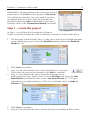
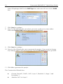
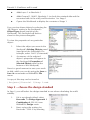
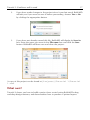
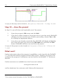
Geocentrix
ReWaRD 2.7
Quick-Start Guide
Embedded retaining wall design
2
Geocentrix ReWaRD 2.7 Quick-Start Guide
Notices
Information in this document is subject to change without notice and does not
represent a commitment on the part of Geocentrix Ltd. The software described in
this document is furnished under a licence agreement or non-disclosure agreement
and may be used or copied only in accordance with the terms of that agreement. It
is against the law to copy the software except as specifically allowed in the licence
or non-disclosure agreement. No part of this manual may be reproduced or
transmitted in any form or by any means, electronic or mechanical, including
photocopying and recording, for any purpose, without the express written
permission of Geocentrix Ltd.
©1992-2013 Geocentrix Ltd. All rights reserved.
“Geocentrix” and “ReWaRD” are registered trademarks of Geocentrix Ltd. Other
brand or product names are trademarks or registered trademarks of their respective
holders.
Set in Optimum using Corel® WordPerfect® X5. Printed in the UK.
Acknowledgments
ReWaRD was originally commissioned by British Steel Ltd (now part of Tata Steel).
ReWaRD 2.x was designed and written by Dr Andrew Bond of Geocentrix, with
the assistance of Ian Spencer of Honor Oak Systems.
The ReWaRD Quick-Start Guide was written by Andrew Bond.
Parts of ReWaRD were developed with the assistance of Professor David Potts of
Imperial College of Science, Technology, and Medicine, London, and Dr Hugh St
John of the Geotechnical Consulting Group, London. The following people assisted
with the testing of this and previous versions of the program: Romain Arnould,
Andy Fenlon, Joe Emmerson, Kieran Dineen, and Jenny Bond.
Revision history
th
Last revised 16 May 2013 (for version 2.7.0 RTM).
Table of contents
3
TABLE OF CONTENTS
TABLE OF CONTENTS . . . . . . . . . . . . . . . . . . . . . . . . . . . . . . . . . . . . . . . . . . . . . . 3
INTRODUCING REWARD 2.7 . . . . . . . . . . . . . . . . . . . . . . . . . . . . . . . . . . . . . . .
What’s in ReWaRD 2?
What’s new in ReWaRD 2.7?
Documentation
Quick-start guide (this booklet)
User manual
Reference manual
Help system
Software Re-Assurance™
Notes
5
5
5
6
6
6
6
6
7
7
TUTORIAL 1
CANTILEVER WALL IN SAND . . . . . . . . . . . . . . . . . . . . . . . . . . . . . . . . . . . . . . . . . 8
Overview
8
Step 1 – create the project
9
Step 2 – choose the design standard
11
Step 3 – calculate structural forces
12
14
Step 5 – check the required embedment
16
Step 6 – close the project
16
What next?
17
TUTORIAL 2
PROPPED WALL IN STIFF CLAY . . . . . . . . . . . . . . . . . . . . . . . . . . . . . . . . . . . . . . .
Overview
Step 1 – create the construction stage
Step 2 – create the ground conditions
Step 3 – create the wall and prop
Step 4 – create the borehole
Step 5 – create water tables
Step 6 – choose the design standard
Step 7 – calculate the required embedment
Step 8 – calculate structural forces
Step 9 – print the results
Step 10 – close the project
What next?
18
18
19
20
23
25
28
30
31
31
32
33
34
4
Geocentrix ReWaRD 2.7 Quick-Start Guide
TUTORIAL 3
COFFERDAM IN MIXED SOILS . . . . . . . . . . . . . . . . . . . . . . . . . . . . . . . . . . . . . . .
Overview
Step 1 – create the project
Step 2 – change the excavation depths
Step 3 – add the missing soils
Step 4 – add missing layers
Step 5 – extend the wall and move the top prop
Step 6 – move existing water tables and create new ones
Step 7 – add a surcharge
Step 8 – select the design standard
Step 9 – calculate earth pressures, structural forces, etc.
What next?
35
36
36
39
40
42
43
45
47
48
49
52
Introducing ReWaRD 2.7
5
INTRODUCING REWARD 2.7
ReWaRD® 2.7 provides a rich set of capabilities for engineers to design/analyse:
!
various types of embedded retaining walls, including sheet pile,
diaphragm, secant and contiguous bored pile sections
!
cantilever, single-propped, double-propped, and multi-propped walls
!
in the common soil types, such as gravel, sand, silt, and clay
!
using various current and historical design standards (such as Eurocode 7
and BS 8002)
ReWaRD employs the limiting equilibrium method to analyse cantilever and singlepropped retaining walls; and the ‘hinge method’ to analyse double-propped and
multi-propped walls. Both traditional lumped factors-of-safety and modern partial
factors can be applied in these calculations.
ReWaRD estimates wall movements by reference to a database of measured wall
displacements and ground settlement.
What’s in ReWaRD 2?
!
Drawing Board provides elevation view of your project
!
’Live’ editing of any object in the project
!
Stockyard allows quick access to individual components of the project
!
Program contains over 100 predefined items for use in your project
!
Construction Wizard guides you through setting up sequenced
construction stages
!
Workbook provides a spreadsheet-like display of all results
!
Workbook gives a graphical views of key results
!
Message View records program activities and displays warning and error
messages as appropriate
!
Comprehensive Reference Manual.
What’s new in ReWaRD 2.7?
!
Implementation of Eurocode 7 (EN 1997-1) design rules for Design
Approaches 1, 2, and 3
!
Option to apply partial factors to actions or effects of actions
6
Geocentrix ReWaRD 2.7 Quick-Start Guide
!
Updated user interface, with better organization of menu options
!
Support for running the program on Windows 7
!
Updated User Manual and new Quick-start Guide.
Documentation
ReWaRD 2.7 is supplied with a detailed Quick-start Guide, comprehensive User
Manual, and authoritative Reference Manual. The latest versions of these manuals
(including any corrections and/or additions since the program’s first release) are
available in electronic (Adobe® Acrobat®) format from the Geocentrix website.
(www.geocentrix.co.uk/ReWaRD and follow links to ReWaRD’s documentation).
Quick-start guide (this booklet)
The ReWaRD Quick-start Guide includes three tutorials that show you how to use
the main features of ReWaRD. Each tutorial provides step-by-step instructions on
how to drive the program. The tutorials increase in difficulty and are designed to be
followed in order.
User manual
The ReWaRD User Manual explains how to use ReWaRD. It provides a detailed
description of the program’s user interface.
Reference manual
The ReWaRD Reference Manual gives detailed information about the engineering
theory that underpins ReWaRD’s calculations. The manual assumes you have a
working knowledge of the geotechnical design of embedded retaining walls, but
provides appropriate references for further study if you do not.
Help system
ReWaRD’s help system contains detailed information about the program, including
most of the information contained in the ReWaRD Quick-Start Guide, User Manual,
and Reference Manual – plus additional information regarding ReWaRD that is not
found in any of these documents.
Help appears in a separate window to ReWaRD, allowing you to view the help
topics while you continue to work with ReWaRD itself. To open the help system:
!
Press F1
!
Click the Help button in any dialog box
!
Click on the Help command on ReWaRD’s main menu and select
Introducing ReWaRD 2.7
7
‘Contents’
Software Re-Assurance™
Software Re-Assurance (which includes maintenance updates, version upgrades,
and technical support) for ReWaRD is available direct from Geocentrix or through
your local distributor. To obtain Re-Assurance, please contact Geocentrix as
follows:
ReWaRD Technical Support
Geocentrix Ltd
Scenic House, 54 Wilmot Way
Banstead, Surrey
SM7 2PY, United Kingdom
Please quote your licence number on
all correspondence
Voice: +44 (0)1737 373963
Fax: +44 (0)1737 373980
E-mail: [email protected]
Web: www.geocentrix.co.uk/support
Please be at your computer and have
your licence number ready when you
call
Maintenance updates are available free-of-charge from the Geocentrix website.
Notes
The screenshots in this guide were produced on Windows 7. Your screen may
differ, depending on the version of Windows on which you run ReWaRD. Not all
options are available in every edition of ReWaRD.
In this guide, ‘[Projects]’ refers to the folder where your ReWaRD projects are
saved, typically:
on Windows XP:
C:\Documents and Settings\All Users\Geocentrix\ReWaRD\2.7
on Windows 7 and later:
C:\Users\Public\Documents\Geocentrix\ReWaRD\2.7
8
Geocentrix ReWaRD 2.7 Quick-Start Guide
TUTORIAL 1
CANTILEVER WALL IN SAND
This tutorial demonstrates the basic features of ReWaRD, through a worked
example involving the analysis of a cantilever wall in sand:
!
Ground conditions comprise 15 m of dense sand. The sand has unit
3
weight of 17 kN/m and angle of shearing resistance of 35E.
!
The groundwater table is 15 m below formation level and hence the sand
can be considered dry throughout.
!
The retaining wall, which is made from a 0.6 m thick diaphragm panel,
will support a 4 m deep excavation without the aid of propping.
!
You want to determine the wall’s minimum depth of embedment and the
maximum bending moment and shear force it must resist.
Overview
!
In Step 1, you will use the Construction Wizard to create the scenario
described above, including the wall, a borehole, excavation, and ground
surface.
!
In Step 2, you will select the design standard to use when calculating the
wall’s stability.
!
In Step 3, you will calculate the resultant structural forces (‘effects of
actions’ in Eurocode terms) acting in the retaining wall
!
In Step 4, you will review the earth pressures that were used to calculate
the resultant structural forces acting in the retaining wall.
!
In Step 5, you will determine the depth of embedment required to satisfy
the requirements of Eurocode 7 with regards to overall stability of the
wall.
!
In Step 6, you will close (and optionally save) the project.
If ReWaRD is not already running,
double-click on the ReWaRD icon on
Windows’ Desktop to start the program.
Once the splash screen has disappeared,
ReWaRD displays its Start-up Wizard. Select
Run the Construction Wizard from the
available options and click Go to proceed.
Tutorial 1: Cantilever wall in sand
9
If ReWaRD is already running and you have an existing
project open, click Close on the program’s File menu.
(You will be prompted to save your work if you have
not already done so.) Then, open the Construction
Wizard by selecting Tools on ReWaRD’s main menu
and then click on the Construction Wizard command.
Step 1 – create the project
In Step 1, you will use the Construction Wizard to
create a scenario including the wall, a borehole, excavation, and ground surface.
1
The first page of the Wizard (‘Step 1’) asks you to specify the finished geometry
of the retaining structure. Select the Cantilever button and set the Retained
Height to 4 m.
2
3
Click Next to continue.
Step 2 of the Wizard asks you to enter the depths of any props.
Since there are none in this example, click Next to continue.
Step 3 of the Wizard asks you to enter the properties of the
predominant soil type. Select ‘Sand’ from the Soil Type box; leave the Wet
3
Mass Density at its default value; enter a Dry Mass Density of 1733 kg/m
3
(equivalent to a weight density of 17 kN/m ); and finally enter an Angle of
Friction of 35E.
4
5
6
Click Next to continue.
Step 4 of the Wizard asks you to choose the type of retaining wall to create.
10
Geocentrix ReWaRD 2.7 Quick-Start Guide
Select ‘Diaphragm Wall’ in the Wall Type box and enter 600 mm in the Width
box.
7
8
Click Next to continue.
Step 5 of the Wizard asks you where you want to place any water tables.
Select the Neither Side button (since the ground is dry).
9 Click Next to continue.
10 Step 6 of the Wizard asks you to generate the project. If you want to change
any settings made in the previous steps, click the Previous button to go back.
11 Click Go to generate the project.
The Construction Wizard then:
!
Creates Ground 1, Wall 1, Soil 1, Layer 1, Borehole 1, Stage 1, and
Excavation 1
!
Attaches Soil 1 to Layer 1
Tutorial 1: Cantilever wall in sand
!
Adds Layer 1 to Borehole 1
!
Adds Ground 1, Wall 1, Borehole 1 (on both the retained side and the
excavated side of the wall), and Excavation 1 to Stage 1
!
Opens the Workbook to display the contents of Stage 1
You can view these objects by selecting the
‘All Objects’ option in the Stockyard’s
Object Types panel (top-left of the
Stockyard). The Stockyard will look as
shown in the picture alongside.
To view the properties of any particular
object:
1.
Select the object you want in the
Stockyard’s Existing Objects panel
(top-right of the Stockyard). For
example, select ‘Soil 1 (Generated)’
2.
A summary of the selected
object’s properties will appear in
the Stockyard’s Properties of
Selected Object panel (at the
bottom of the Stockyard)
Now is a good moment to save your work
to disk, which you can do using the Save or
Save As commands on ReWaRD’s File
menu.
A copy of this step can be found at
[Projects]\Tutorial 1\Step 1.rwd.
Step 2 – choose the design standard
In Step 2, you will select the design standard to use when calculating the wall’s
stability.
1.
If it is not already ticked, select
Eurocode 7 > Design Approach 1
Combination 2 (DA1-2) from
ReWaRD’s Design menu.
2.
Next, review the settings for
Eurocode 7 DA1-2 by selecting
11
12
Geocentrix ReWaRD 2.7 Quick-Start Guide
Design Standard... from the from the Properties menu.
3.
Click on the Load Factors tab to
confirm that a partial factor of 1.0 is
applied to permanent and accidental
actions and 1.3 to variable actions (as
per the requirements of EN 1997-1).
4.
Click on the Material Factors tab to
confirm that the factors applied to
tan n and c’ are 1.25 and to cu is 1.4
(again, as per EN 1997-1).
5.
Review other settings by clicking on
the various tabs in turn.
6.
Click OK to close the property box.
A copy of this step can be found at [Projects]\Tutorial 1\Step 2.rwd.
Step 3 – calculate structural forces
In Step 3, you will calculate the resultant structural forces (‘effects of actions’ in
Eurocode terms) acting in the retaining wall.
1.
If it is not already selected, click on the Workbook to make it active. (The
commands on the Calculate menu are only enabled when a Workbook
is selected.)
2.
Open the Calculate menu and choose the Structural Forces command.
Alternatively, click on the Calculate structural Forces button on the
Workbook’s toolbar (a tooltip will popup when you hover the mouse
over the button).
Tutorial 1: Cantilever wall in sand
13
3.
ReWaRD then calculates the
wall’s required embedment
with the selected partial
factors applied and uses those
earth pressures to calculate
the resultant structural forces
in the wall. The program
displays its results pictorially,
as shown on the right. The
largest factored bending
moment and shear force in
the wall are also given. In
Eurocode terms, these are
ultimate limit state design values.
4.
You can view numerical
values of the structural forces
by selecting Table on the
Workbook’s View menu.
Columns B to E show
structural forces without
partial factors applied to the
effects of actions; columns F
to I show them with the
partial factors applied. (Since the partial factor applied to effects of
actions according to EN 1997-1 is 1.0, these values are the same in this
instance.)
5.
You can search for the maximum bending moment in the wall as follows.
First, click anywhere in the Moment Factored column. Then open the
Edit menu and choose the Find command. Alternatively, click on the
Find button on the Stockyard’s toolbar.
6.
In the Find box that appears, select
what you want to search for (e.g. the
Maximum) and click OK to perform
the search. The Workbook display will
scroll to show the maximum bending
moment along the wall.
A copy of this step can be found at
[Projects]\Tutorial 1\Step 3.rwd.
14
Geocentrix ReWaRD 2.7 Quick-Start Guide
Step 4 – review earth pressures
In Step 4, you will review the earth pressures that were used to calculate the
resultant structural forces acting in the retaining wall.
1.
To display the earth pressures that were used to calculate structural
forces, open the View menu and choose the Earth Pressures > At
Minimum Safe Embedment command. To display the results in graphical
form, re-open the View menu and choose the Picture command.
2.
The drawing shows active and passive earth pressures on either side of
the wall; and indicates (with a red dashed line) the extent of the
unplanned excavation that has automatically been taken into account.
The depth of the earth pressures corresponds to the minimum safe
embedment of the wall. These earth pressures are in equilibrium, with
partial factors from the specified design standard applied.
3.
You can display earth pressures over the full extent of the wall, as follows.
Open the Calculate menu and choose the Earth Pressures > As Built
command. (ReWaRD will automatically display the results of this
calculation when it has finished. Earth pressures for the ‘as built’
condition have partial factors applied in their calculation, but are not
normally in equilibrium, unless the wall’s embedded length happens to
match that required by those factors. See the ReWaRD Reference Manual
for an explanation of the different types of earth pressure that the
program calculates.
Tutorial 1: Cantilever wall in sand
15
4.
You can display earth pressures at the point at which the wall would fail
(i.e. with no safety margin built in), as follows. Open the Calculate menu
and choose the Earth Pressures > At Failure command. Earth pressures
for the ‘at failure’ condition are in equilibrium but have no partial factors
applied in their calculation.
5.
You can view numerical
values of any of these earth
pressures by selecting Table
on the Workbook’s View
menu. In its default
appearance, the Table View
displays design values of
earth, water, and total
pressures on both sides of the wall.
6.
You can view the earth pressure
coefficients used in the calculations, by
selecting Earth Pressures >
Coefficients on the Workbook’s View
menu. In this appearance, the Table
View displays design values of K and
Kc on both sides of the wall (i.e. Ka and
Kac on the retained side and Kp and Kpc
on the excavated side).
7.
Finally, you can view all the values used to calculate earth pressures, by
selecting Earth Pressures > All on the Workbook’s View menu. In this
appearance, the Table View displays the results of every step in the
calculations (see the ReWaRD Reference Manual for details).
16
Geocentrix ReWaRD 2.7 Quick-Start Guide
A copy of this step can be found at [Projects]\Tutorial 1\Step 4.rwd.
Step 5 – check the required embedment
In Step 5, you will determine the depth of embedment required to satisfy the
requirements of Eurocode 7 with regards to overall stability of the wall.
1.
Open the Calculate menu and choose
the Required Embedment command.
(ReWaRD automatically switches the
Workbook to its Summary View.)
2.
The Workbook displays its results in a
tree-like structure, similar to that used
in Windows Explorer. You can expand
any particular node by clicking on the
+ button next to its caption; and you
can collapse a node by clicking on the
! button.
3.
The required embedment of the wall is displayed under the At Minimum
Safe Embedment branch of this tree structure.
4.
To see the partial factors that were
applied in the At Minimum Safe
Embedment calculation, expand the
Partial Factors branch by clicking on
its + button. Then click on the +
button next to Factors on material
properties. The Workbook will display
the values of the partial factors that
were applied to shearing resistance
(1.25), effective cohesion (1.25), and
undrained strength (1.40).
A copy of this step can be found at
[Projects]\Tutorial 1\Step 5.rwd.
Step 6 – close the project
1
In Step 6, you will close and (optionally) save the project.
1.
1
Open the program’s File menu and click Exit.
You cannot save the project in the Trial Edition of ReWaRD
Tutorial 1: Cantilever wall in sand
17
2.
If you have made changes to the project since it was last saved, ReWaRD
will ask you if you want to save it before proceeding. Answer Yes or No
by clicking the appropriate button.
3.
If you have not already named this file, ReWaRD will display its Save As
box. Enter the name you want in the File name box and click the Save
button. ReWaRD will then save and close the project.
A copy of this project can be found at [Projects]\Tutorial 1\Tutorial
1.rwd.
What next?
Tutorial 2 shows you how to build a project from scratch using ReWaRD’s dragand-drop design features; and demonstrates how to produce a printed report.
18
Geocentrix ReWaRD 2.7 Quick-Start Guide
TUTORIAL 2
PROPPED WALL IN STIFF CLAY
Tutorial 2 helps you to extend your knowledge of ReWaRD, by designing a
propped wall in stiff clay. The tutorial shows you how to build a project from
scratch, without using the Construction Wizard; drag engineering objects from the
Stockyard and drop them onto a Workbook's Drawing Board; and obtain a printout
of your input and output data.
The worked example is taken from CIRIA Report 104, Design of retaining walls
embedded in stiff clays (by Padfield and Mair, 1984). Appendix C of that report
includes calculations for propped walls in stiff clay with and without seepage
around the wall. Example C.2 involves design of a wall supporting an excavation in
stiff clay.
!
Ground conditions at the site comprise an unspecified thickness of stiff
3
clay ((dry = (sat = 20 kN/m ; n = 25E; c’ = 0 kPa).
!
Groundwater is at 1 m below ground level on the retained side of the
wall and at 1 m below formation level on the excavated side.
!
The wall (type unspecified, but assumed herein to be secant piled) will
form part of the temporary works and will retain 8 m of soil.
!
The wall is supported by a prop at 2 m below ground level.
!
You want to calculate the wall's minimum depth of embedment; the
maximum bending moment and shear force in the wall; and the force in
the prop.
Overview
!
In Step 1, you will create a construction stage and display its Workbook
showing a blank Drawing Board.
!
In Step 2, you will define the geometry of the ground on both sides of
the wall.
!
In Step 3, you will create a retaining wall of the appropriate type, specify
its length and cross-sectional properties, and then create a prop to
support the wall.
!
In Step 4, you will specify ground conditions at the site – using a soil to
represent the properties of the clay, a layer to represent the geometry
and drainage conditions of that soil, and a borehole to represent the
elevation and ordering of the layers.
Tutorial 2: Propped wall in stiff clay
19
!
In Step 5, you will create two water tables, one on each side of the wall.
!
In Step 6, you will select the design standard to use when calculating the
wall’s stability.
!
In Step 7, you will determine the required embedment for this design
situation, according to CIRIA 104’s Gross Pressure Method.
!
In Step 8, you will determine the resulting structural forces in the wall
according to CIRIA 104.
!
In Step 9, you will obtain a hard copy of your results.
!
In Step 10, you will close (and optionally save) the project.
If ReWaRD is not already running, double-click on the ReWaRD icon on Windows’
Desktop to start the program. Once the splash screen has disappeared, ReWaRD
displays its Start-up Wizard. Select Create new project from the available options
and click Go to proceed.
If ReWaRD is already running and you have an existing project open, click New on
the program’s File menu. (You will be prompted to save your work if you have not
already done so.)
Step 1 – create the construction stage
In Step 1, you will create a construction stage and display its Workbook showing a
blank Drawing Board.
1.
Open the program’s Create menu and click on
Construction Stage... to display the Create
Construction Stage box. Alternatively, click on the
Create Construction Stage button on the
Stockyard’s Toolbar.
2.
The Create Construction Stage box will open.
Since there is only one option to choose from,
click the OK button to proceed.
3.
The ‘Properties of Construction Stage 1’ box
will open. This is a multi-paged dialog box that
allows you to set the properties of the newlycreated construction stage. Change the Name
of the construction stage to ‘Example C2’ and click OK to proceed. (The
stage’s other properties will be set later.)
20
Geocentrix ReWaRD 2.7 Quick-Start Guide
4.
ReWaRD will create a new construction stage with the name ‘Example
C2’, add it to the Stockyard, and then open a Workbook showing the
contents of that stage (which is currently empty). Your screen should
now look something like this:
A copy of this step can be found at [Projects]\Tutorial 2\Step 1.rwd.
Step 2 – create the ground conditions
In Step 2, you will define the geometry of the ground on both sides of the wall.
1.
Click on the Stockyard to make sure it is selected (the commands on the
Create menu are only enabled when the Stockyard is selected).
2.
Open the program’s Create menu and click on Ground Profile... to
display the Create Ground Profile box. Alternatively, click on the Create
Ground Profile button on the Stockyard’s Toolbar.
3.
The Create Ground Profile box will open.
Select ‘Horizontal Ground’ and click OK to
proceed.
Tutorial 2: Propped wall in stiff clay
21
4.
The ‘Properties of Ground Profile 1’ box will open and display its General
page. Change the Name of the ground profile to ‘Ground Surface’ and
click OK to proceed.
5.
ReWaRD will create a new ground profile named ‘Ground Surface’ and
add it to the Stockyard. To add this ground profile to the construction
stage, you drag it from the Stockyard onto the Workbook’s Drawing
Board. To do so...
6.
First, with the cursor located over the
‘Ground Surface’ item in the
Stockyard, click – and hold down –
the left mouse button to select that
item.
7.
Second, without releasing the mouse
button, move (drag) the cursor over
the Workbook (anywhere where do).
The cursor will change to indicate
where you can drop this item.
8.
Finally, release the left mouse button
to drop the ground profile into the
construction stage. The ground profile
will immediately appear on the
drawing, to the left of the vertical
datum line.
9.
Now repeat the above steps for an excavation. Click on the Stockyard to
make sure it is selected (the commands on the Create menu are only
enabled when the Stockyard is selected).
10.
Open the program’s Create menu and click on
Excavation... to display the Create Excavation box.
Alternatively, click on the Create Excavation
button on the Stockyard’s Toolbar.
22
Geocentrix ReWaRD 2.7 Quick-Start Guide
11.
The Create Excavation box will open. Select
‘Horizontal Excavation’ and click OK to
proceed.
12.
The ‘Properties of Excavation 1’ box will open.
Change the Name of the excavation to ‘8 m
dig’.
13.
Click on the Dimensions tab to change page.
Change the Depth of the excavation to 8 m and click OK to proceed.
(The Plan Dimensions of this object will take on default values.)
14.
ReWaRD will create a new excavation
named ‘8 m dig’ and add it to the
Stockyard. To add the excavation to
the construction stage, drag it from
the Stockyard and drop it onto the
Workbook’s Drawing Board as
explained above.
15.
When you release the left mouse button to drop the excavation into the
construction stage, it will immediately appear on the drawing, to the right
of the vertical datum line. The Drawing Board should now look like this:
Tutorial 2: Propped wall in stiff clay
23
A copy of this step can be found at [Projects]\Tutorial 2\Step 2.rwd.
Step 3 – create the wall and prop
In Step 3, you will create a retaining wall of the appropriate type, specify its length
and cross-sectional properties, and then create a prop to support the wall.
1.
Click on the Stockyard to make sure it is selected (the commands on the
Create menu are only enabled when the Stockyard is selected).
2.
Open the program’s Create menu and click on Retaining Wall... to
display the Create Retaining Wall box. Alternatively, click on the Create
Retaining Wall button on the Stockyard’s Toolbar.
3.
The Create Retaining Wall box will open.
Select ‘Secant Pile Wall’ and click OK to
proceed.
4.
The ‘Properties of Retaining Wall 1’ box will
open. Change the Name of the wall to ‘20 m
long wall’.
5.
Click on the Dimensions tab to change page. Change the Toe Depth of
the wall to 20 m.
6.
Click on the Section tab to change page.
Change the Diameter of the piles to 750 mm
and click OK to proceed. An error message
will appear telling you that the ‘Spacing must
be between 100 mm and 750 mm’. (Since this
is a secant piled wall, the spacing must not
exceed the piles’ diameter.) Change the Spacing of the piles to 600 mm
and click OK to proceed. The remaining sectional properties update as
you do so.
24
Geocentrix ReWaRD 2.7 Quick-Start Guide
7.
ReWaRD will create a new retaining wall named ‘20 m long wall’ and
add it to the Stockyard. To add the wall to the construction stage, drag it
from the Stockyard and drop it onto the Workbook’s Drawing Board.
8.
Now repeat the above steps for the prop. Click on the Stockyard to
make sure it is selected. Open the program’s Create menu and click on
Prop... to display the Create Prop box. Alternatively, click on the Create
Prop button on the Stockyard’s Toolbar.
9.
The Create Prop box will open. Select
‘Horizontal Prop’ and click OK to proceed.
10.
The ‘Properties of Prop 1’ box will open and
display its General page. Change the Name of
the prop to ‘Prop at 2 m’.
11.
Click on the Dimensions tab to change page.
Change the Depth of the prop to 2 m and
click OK to proceed.
12.
ReWaRD will create a new prop named ‘Prop at 2 m’ and add it to the
Stockyard. To add the prop to the construction stage, drag it from the
Stockyard and drop it onto the Workbook’s Drawing Board.
13.
Right-click on the Drawing Board’s ruler to change its scale to 1:250 (if
not already set to this value). The Drawing Board should now look like
Tutorial 2: Propped wall in stiff clay
25
this:
A copy of this step can be found at [Projects]\Tutorial 2\Step 3.rwd.
Step 4 – create the borehole
In Step 4, you will specify ground conditions at the site – using a soil to represent
the properties of the clay, a layer to represent the geometry and drainage
conditions of that soil, and a borehole to represent the elevation and ordering of
the layers. This step will also demonstrate a quicker way to create objects.
1.
Right-click on the word ‘Soil’ in the
Stockyard’s Types Pane to display its
context-sensitive menu. Click New to
expand the sub-menu and then click
Clay to create the new soil.
Alternatively, click on the Create Soil
button on the Stockyard’s Toolbar.
2.
The ‘Properties of Soil 1’ box will open and display its General page.
Change the Name of the soil to ‘Stiff clay’.
3.
Click on the Classification tab to change page. Change the soil’s State to
‘Stiff’.
4.
Click on the Density/Weight tab to change page. If not already selected,
click on the Weight Density button. Then (if necessary), change the soil’s
3
Saturated and Unsaturated weight densities to 20 kN/m .
5.
Click on the Effective Stress tab to change page. Change the soil’s Angle
of Friction (i.e. shearing resistance) to 25E, but leave the other properties
26
Geocentrix ReWaRD 2.7 Quick-Start Guide
unchanged.
6.
Click on the Total Stress tab to change page. Change the soil’s undrained
strength to 60 kPa.
7.
Click on the Notes tab to change
page. When you do so, a warning
message will appear telling you that
the ‘soil parameter is outside the
normal range’. This occurs because for
a clay specified as stiff, ReWaRD
expects its strength to be between 75
and 150 kPa. The entered value of
60 kPa will be accepted, but only after confirmation via this warning box.
Click Yes to confirm the value and proceed.
8.
Click on the Notes tab again and then add any information you want to
attach to this soil via the text control there. Finally, click OK to confirm
the entered values and to proceed. ReWaRD will create a new soil
named ‘Stiff clay’ and add it to the Stockyard.
9.
Next, right-click on the word ‘Layer’ in
the Stockyard’s Types Pane to display
its context-sensitive menu. Click New
to expand the sub-menu and then
click Undrained Layer to create a new
layer.
10.
The ‘Properties of Layer 1’ box will
open and display its General page.
11.
Click on the Properties tab to change page. Change the Soil to ‘Stiff clay’
and change the layer’s Thickness to 30 m. Click OK to confirm these
settings and to proceed. ReWaRD will create a new layer named ‘Layer
1’ and add it to the Stockyard.
Tutorial 2: Propped wall in stiff clay
27
12.
Finally, right-click on the word
‘Borehole’ in the Stockyard’s Types
Pane to display its context-sensitive
menu. Click New to expand the submenu and then click Borehole to
create a new borehole.
13.
The ‘Properties of Borehole 1’ box will
open and display its General page.
14.
Click on the Layers tab to change
page. Select ‘Layer 1’ in the Available box and click the --> button to
move it into the Chosen box. Click OK to confirm these settings and to
proceed.
15.
ReWaRD will create a new borehole named ‘Borehole 1’ and add it to
the Stockyard. To add the borehole to the construction stage, drag it
from the Stockyard and drop it onto the Workbook’s Drawing Board. The
Drawing Board should now look like this:
28
Geocentrix ReWaRD 2.7 Quick-Start Guide
A copy of this step can be found at [Projects]\Tutorial 2\Step 4.rwd.
Step 5 – create water tables
In Step 5, you will create two water tables, one on each side of the wall.
1.
Right-click on the words ‘Water Table’
in the Stockyard’s Types Pane to
display its context-sensitive menu.
Click New to expand the sub-menu
and then click Linear Seepage Water
table to create the new water table.
2.
The ‘Properties of Water Table 1’ box
will open and display its General
page. Change the Name of the water
table to ‘Retained water’.
3.
Click on the Properties tab to change page. Change the water table’s
Depth to 1 m. Click OK to confirm the entered values and to proceed.
4.
ReWaRD will create a new water table named ‘Retained water’ and add
it to the Stockyard.
Tutorial 2: Propped wall in stiff clay
29
5.
Repeat the previous steps to create a second Linear Seepage Water
Table named ‘Excavated water’ at a depth of 9 m.
6.
Add the two water tables to the construction stage, by dragging them
from the Stockyard and dropping them onto the Workbook’s Drawing
Board. The ‘Retained water’ object should be dropped to the left of the
wall and the ‘Excavated water’ object to the right. The Drawing Board
should now look like this:
7.
If you make a mistake dropping the water tables, so that they do not
appear as shown above, then you can rectify this by dragging them back
into the Stockyard.
8.
Alternatively, double-click on any white area on the Drawing Board to
display the Construction Stage’s properties box. Click on the Water
Tables tab to change page. Then change the tick marks in the On
Retained Side and On Excavated Side boxes to match the screenshot
below. Click OK to confirm and to proceed.
A copy of this step can be found at [Projects]\Tutorial 2\Step 5.rwd.
30
Geocentrix ReWaRD 2.7 Quick-Start Guide
Step 6 – choose the design standard
In Step 6, you will select the design standard to use to when calculating the wall’s
stability.
1.
If it is not already ticked, select
CIRIA 104 > Gross Pressure
Method from ReWaRD’s Design
menu.
2.
Next, edit the settings for CIRIA
104 Gross Pressure Method by
selecting Design Standard... from
the Properties menu.
3.
On the General page, set the Design Approach to ‘Moderately
Conservative’ and the Works to ‘Temporary’.
4.
Click on the Resistance Factors tab to change page. Confirm that the
factors applied to drained parameters are 1.2 for n # 20E, 1.5 for n $
30E, and 2.0 for undrained parameters (as per CIRIA 104).
5.
Review other settings by clicking on the various tabs in turn. When you
have finished, click OK to close the property box.
Tutorial 2: Propped wall in stiff clay
31
A copy of this step can be found at [Projects]\Tutorial 2\Step 6.rwd.
Step 7 – calculate the required embedment
In Step 7, you will determine the required embedment for this design situation,
according to CIRIA 104’s Gross Pressure Method.
1.
If it is not already selected, click on the Workbook to make it active. (The
commands on the Calculate menu are only enabled when a Workbook
is selected.)
2.
Open the Calculate menu
and choose the Required
Embedment command.
(ReWaRD automatically
switches the Workbook to its
Summary View.)
3.
Expand the Partial Factors
node to display more of the
tree-structure, by clicking on
the + button next to its
caption. Then expand the
Factors on resistance and Factors on structural forces nodes to display
the partial factors that have been applied in this calculation.
4.
The required embedment of the wall is displayed under the At Minimum
Safe Embedment, next to the Depth of toe node. CIRIA 104 reports the
depth of embedment as 7.5 m, which – when added to the retained
height of 8 m – gives a toe depth of 15.5 m.
A copy of this step can be found at [Projects]\Tutorial 2\Step 7.rwd.
Step 8 – calculate structural forces
In Step 8, you will determine the resulting structural forces in the wall according to
CIRIA 104.
1.
If it is not already selected, click on the Workbook to make it active. (The
commands on the Calculate menu are only enabled when a Workbook
is selected.)
32
Geocentrix ReWaRD 2.7 Quick-Start Guide
2.
Open the Calculate menu
and choose the Structural
Forces command. (ReWaRD
automatically switches the
Workbook to its Picture
View.)
3.
ReWaRD then calculates the
resultant structural forces in
the wall and displays the
results pictorially, as shown on
the right. The largest factored
bending moment and shear
force in the wall are also given. CIRIA 104 (on page 137) reports the
maximum unfactored bending moment as 627 kNm/m (corresponding to
a factored bending moment of 627 x 1.5 = 940.7 kNm/m); and the
maximum unfactored shear forces as 232 kN/m (corresponding to a
factored shear force of 232 x 1.5 = 324 kN/m).
A copy of this step can be found at [Projects]\Tutorial 2\Step 8.rwd.
Step 9 – print the results
In Step 9, you will obtain a hard copy of your results.
1.
Click on ReWaRD’s File menu and
choose Print > Page Setup... to display
the program’s Print Page Setup box.
2.
On Stockyard page, tick those objects
about which you want information to
be printed.
3.
Click on the Workbooks tab to
change page and again tick those
objects about which you want information to be printed. Note that this
page automatically selects construction stages for which calculations
have already been performed.
4.
Click on the Pictures tab to change
page and tick those components of
the results that you want to be
printed.
5.
Finally, click on the Results tab to
change page and tick those results
you want to be printed.
6.
Click OK to confirm your selections
Tutorial 2: Propped wall in stiff clay
33
and proceed.
7.
Next, click on ReWaRD’s File menu and choose Print > Print Preview to
display a screen preview of the printed output.
8.
Use the controls on the toolbar at the top of the preview window to
control the appearance of the print preview. Click the X button to close
the preview window.
9.
Finally, click on ReWaRD’s File menu
and choose Print > Print.... The
program’s Print Page Setup box will
be displayed once again (in case you
wish to change any of your
selections). Click OK to confirm and –
this time – the program’s Print box
will appear, giving you a choice of
printers attached to your system to
choose from.
10.
Select your printer and click Print to
produce the hard copy.
A copy of this step can be found at [Projects]\Tutorial 2\Step 9.rwd.
Step 10 – close the project
2
In Step 10, you will close and (optionally) save the project.
2
You cannot save the project in the Trial Edition of ReWaRD
34
Geocentrix ReWaRD 2.7 Quick-Start Guide
1.
Open the program’s File menu and click Exit.
2.
If you have made changes to the project since it was last saved, ReWaRD
will ask you if you want to save it before proceeding. Answer Yes or No
by clicking the appropriate button.
3.
If you have not already named this file, ReWaRD will display its Save As
box. Enter the name you want in the File name box and click the Save
button. ReWaRD will then save and close the project.
A copy of this project can be found at [Projects]\Tutorial 2\Tutorial
2.rwd.
What next?
Tutorial 3 takes you through the design of a more complicated structure – a multipropped cofferdam in mixed soils – using the techniques introduced in Tutorials 1
and 2.
Tutorial 3: Cofferdam in mixed soils
35
TUTORIAL 3
COFFERDAM IN MIXED SOILS
Tutorial 3 helps you to get to grips with ReWaRD’s more advanced features, by
building a multi-propped cofferdam in a mixed soil profile. The tutorial shows you
how to change engineering objects generated by ReWaRD’s Construction Wizard;
add new engineering objects as needed; choose between the available design
standards; check the results of your calculations; and customize the printed output.
The worked example is taken from CIRIA’s Special Publication 95, The design and
construction of sheet-piled cofferdams, by Williams and Waite (1993). Appendix B
of that document describes the design of a sheet pile cofferdam used to support a
sub-surface tank in a mixed soil profile.
!
Ground conditions at the site comprise: 4 m of sand and gravel ((dry = 18
3
3
kN/m ; (sat = 20.3 kN/m ; n = 35E); 2.5 m of firm clay ((sat = 21kN/m³; cu
= 60kPa); 3 m of silty sand ((sat = 20.3kN/m³; n = 30E); 2 m of soft/firm
clay ((sat = 20kN/m³; cu = 40kPa); and medium coarse sand ((sat =
20.3kN/m³; n = 35E).
!
The cofferdam will be open for less than 3 months and open to full
excavation depth for no more than two weeks (hence a total stress
analysis is appropriate).
!
Ground water level is 2.5 m below ground surface. Water pressures in
the medium coarse sand are sub-artesian, with a pressure head of 80 kPa
at the surface of the sand. A pumping system will be installed to lower
the water pressures in the medium coarse sand by 80 kPa throughout the
depth of interest.
!
The permanent works are to be constructed on top of a base slab at a
depth of 8 m. A 0.5 m thick drainage layer is to be placed beneath the
base slab, so that the final formation is at a depth of 8.5 m. The sheet
piles will have an upstand of 1 m.
!
The first frame will be installed at 0.5 m above ground level and the
excavation taken down to 5 m before installing the second frame. The
second frame will be installed at a depth of 4 m and the excavation taken
down to 7.5 m before installing the third frame. The third frame will be
installed at a depth of 6.5 m.
!
The plan dimensions of the cofferdam are 17 m by 12 m.
Overview
36
Geocentrix ReWaRD 2.7 Quick-Start Guide
!
In Step 1, you will use the Construction Wizard to create a sequence of
construction stages.
!
In Step 2, you will change the depths of the excavations generated by the
Construction Wizard to match the project’s specification.
!
In Step 3, you will add soils that are missing from the project.
!
In Step 4, you will add layers that are missing from the project and
include them in the borehole.
!
In Step 5, you will add an upstand to the wall and relocate the top prop
to the head of the wall.
!
In Step 6, you will change the depth of some of the existing water tables
and add new water tables.
!
In Step 7, you will add a surcharge on the retained side of the wall.
!
In Step 8, you will select the design standard to be followed by the
calculations.
!
In Step 9, you will calculate earth pressures, required embedment,
structural forces, and displacements for ‘Stage 2 (Generated)’.
!
In Step 10, you will close (and optionally save) the project.
If ReWaRD is not already running, double-click on the ReWaRD icon on Windows’
Desktop to start the program. Once the splash screen has disappeared, ReWaRD
displays its Start-up Wizard. Select Run the Construction Wizard from the available
options and click Go to proceed.
If ReWaRD is already running and you have an existing project open, click Close
on the program’s File menu. (You will be prompted to save your work if you have
not already done so.) Then, open the Construction Wizard by selecting Tools on
ReWaRD’s main menu and then click on the Construction Wizard command.
Step 1 – create the project
In Step 1, you will use the Construction Wizard to create a sequence of
construction stages to model the multi-staged construction outlined in the project’s
specification.
1.
The first page of the Wizard (‘Step 1’) asks you to specify the finished
geometry of the retaining structure. Select the Multi-propped button, set
the Number of Props to 3, and set the Retained Height to 8.5 m. Click
Next to continue.
Tutorial 3: Cofferdam in mixed soils
37
2.
Step 2 of the Wizard asks you to enter the depths of the props. You want
to place the first prop at 0.5m above ground level, but the Construction
Wizard will not allow you to enter negative depths. Therefore, leave Prop
1 at ground level temporarily (you will change its depth later). Select Prop
2, enter 4 m in the Depth box, and click the Apply button. Then select
Prop 3, enter 6.5 m in the Depth box, and click Apply. Click Next to
continue.
3.
Step 3 of the Wizard asks you to enter the properties of the predominant
soil type. (In this example, we will treat the sand and gravel as the
predominant soil type.) Select ‘Sand’ from the Soil Type box; enter a Wet
3
Mass Density of 2069 kg/m (equivalent to a weight density of 20.3
3
3
kN/m ); enter a Dry Mass Density of 1766 kg/m (equivalent to
3
18 kN/m ); and finally enter an angle of friction of 35E. Click Next to
continue.
38
Geocentrix ReWaRD 2.7 Quick-Start Guide
4.
Step 4 of the Wizard asks you to choose the type of retaining wall to
create. Select ‘Sheet Pile Wall’ in the Wall Type box, then ‘Corus U
Section (Larssen, LX)’ in the Range box, and finally ‘16W’ in the Section.
Click Next to continue.
5.
Step 5 of the Wizard asks you where you want to place any water tables.
Select Both Sides and click Next to continue.
6.
Step 6 of the Wizard asks you to generate the project. If you want to
change any settings made in the previous steps, click the Previous button
to go back. Otherwise, click Go to generate the project.
The Construction Wizard then:
!
Creates Stages 1, 2, 3, and 4
!
Creates Ground 1 and Excavations 1 to 4
!
Creates Soil 1, Layer 1, and Borehole 1
!
Creates Water Tables 1 to 5
!
Creates Wall 1 and Props 1, 2, and 3
!
Attaches Soil 1 to Layer 1 and adds Layer 1 to Borehole 1
!
Adds Ground 1, Wall 1, Borehole 1 (on both sides of the wall), and
Water Table 1 to all stages
!
Adds Excavation 1 and Water Table 2 to Stage 1
Tutorial 3: Cofferdam in mixed soils
!
Adds Excavation 2, Water Table 3, and Prop 1 to Stage 2
!
Adds Excavation 3, Water Table 4, and Prop 2 to Stage 3
!
Adds Excavation 4, Water Table 5, and Prop 3 to Stage 4
!
Opens the Workbooks for Stages 1 to 4
39
Now is a good moment to save your work to disk, which you can do using the
Save or Save As commands on ReWaRD’s File menu.
A copy of this step can be found at [Projects]\Tutorial 3\Step 1.rwd.
Step 2 – change the excavation depths
In Step 2, you will change the depths of the excavations generated by the
Construction Wizard to match the project’s specification.
1.
Open the program’s Window menu and click Tile
to change the arrangement of the open
Workbooks. (In this arrangement, you will see the
effect of each change in property as it is applied.)
2.
Click on ‘Excavation’
in the Stockyard’s
Types Pane (top-left)
and then right-click
on ‘Excavation 2
(Generated)’ in its
Objects Pane (top-right). Choose the command Properties of Excavation
2 (Generated)... to display that object’s properties box.
3.
Click on the Dimensions tab to change page and enter 5 m in the
excavation’s Depth box.
4.
Click on the Plan Dimensions tab to change page. Tick the Has Plan
Length box and enter 17 m in the Length box. Tick the Has Plan Breadth
box and enter 12 m in the Breadth box.
40
Geocentrix ReWaRD 2.7 Quick-Start Guide
5.
Click OK to confirm the values entered and to proceed.
6.
Repeat the previous four steps for Excavations 3 and 4, but enter their
depths of excavation as 7.5 m and 8.5 m respectively.
A copy of this step can be found at [Projects]\Tutorial 3\Step 2.rwd.
Step 3 – add the missing soils
In Step 3, you will add soils that are missing from the project.
1.
Click on ‘Soil’ in the
Stockyard’s Types
Pane and then rightclick on ‘Soil 1
(Generated)’ in its
Objects Pane.
Choose the
command Properties of Soil 1 (Generated)... to display that object’s
properties box.
2.
On the General page, change the soil’s Name to ‘Sand and gravel’.
3.
Click on the Classification tab to change page, but leave the soil’s the
Class as ‘Unclassified’ and State as ’Unspecified’.
4.
Click on the Density/Weight tab to change page. If not already selected,
select the Weight density button. Enter the soil’s Saturated weight
3
3
density as 20.3 kN/m and its Unsaturated weight density as 18 kN/m . If
you get a warning message when you proceed on the next step, click Yes
to confirm the values entered.
Tutorial 3: Cofferdam in mixed soils
41
5.
Click on the Effective Stress tab to change page. If not already selected,
select the Peak button. Enter the soil’s Angle of Friction as 35E and its
Effective Cohesion as 0 kPa.
6.
Click on the OK button to confirm the values entered and to proceed.
7.
Now right-click on ‘Soil’ in the
Stockyard’s Types Pane and choose the
command New > Clay to create a new
clay and display that object’s
properties box.
8.
Repeat the steps above to set the
properties of this new soil, as follows:
Name = ‘Firm clay’; State = ‘Firm’;
Saturated and Unsaturated weight
3
densities both = 21 kN/m ; Angle of
Friction and Effective Cohesion both
take default values. If you get warning messages when you enter any
values, click Yes to confirm them.
9.
Then click on the Total Stress tab to change page. Enter the soil’s
Undrained Strength as 60 kPa.
42
Geocentrix ReWaRD 2.7 Quick-Start Guide
10.
Click on the OK button to confirm the values entered and to proceed.
11.
Repeat the steps above to create a new sand with the following
properties: Name = ‘Silty sand’; Class = ‘Silty’; Saturated and
3
Unsaturated weight densities both = 20.3 kN/m ; Angle of Friction =
30E and Effective Cohesion = 0 kPa. If you get warning messages when
you enter any values, click Yes to confirm them.
12.
Repeat the steps above to create a new clay with the following
properties: Name = ‘Soft/firm clay’; State = ‘Soft’; Saturated and
3
Unsaturated weight densities both = 20 kN/m ; Angle of Friction = 30E
and Effective Cohesion = 0 kPa; Undrained Strength = 40 kPa. If you get
warning messages when you enter any values, click Yes to confirm them.
13.
Finally, right-click on ‘Sand and gravel’
in the Stockyard’s Existing Objects
Pane and choose the command
Duplicate to create a carbon copy of
that soil, called ‘Soil 1’.
14.
Then edit ‘Soil 1’ in order to change its
name to ‘Medium coarse sand’.
You will find a copy of the project in its current
state at [Projects]\Tutorial 3\Step
3.rwd.
Step 4 – add missing layers
In Step 4, you will you will add layers that are missing from the project and include
them in the borehole.
1.
Click on ‘Layer’ in the
Stockyard’s Types
Pane and then rightclick on ‘Layer 1
(Generated)’ in its
Objects Pane.
Choose the
command Properties of Layer 1 (Generated)... to display that object’s
properties box.
2.
On the General page, change the layer’s Name to ‘Layer 1’.
3.
Click on the Properties tab to change page, change the Soil to ‘Sand and
gravel’ and enter the Thickness as 4 m.
Tutorial 3: Cofferdam in mixed soils
43
4.
Click on the OK button to confirm the values entered and to proceed.
The boreholes displayed on the Drawing Board of each stage will update
to reflect this layer’s new thickness.
5.
Now right-click on ‘Layer’ in the
Stockyard’s Types Pane and choose the
command New > Undrained Layer to
create a new undrained layer and
display that object’s properties box.
6.
Repeat the steps above to set the
properties of this new layer, as follows:
Name = ‘Layer 2’; Soil = ‘Firm clay’;
Thickness = 2.5 m.
7.
Repeat the steps above to create a Drained Layer with the properties:
Name = ‘Layer 3’; Soil = ‘Silty sand’; Thickness = 3 m.
8.
Repeat the steps above to create another Undrained Layer with the
properties: Name = ‘Layer 4’; Soil = ‘Soft/firm clay’; Thickness = 2 m.
9.
Repeat the steps above to create another Drained Layer with the
properties: Name = ‘Layer 5’; Soil = ‘Medium coarse sand’; Thickness = 5
m.
10.
Add Layers 2 to 5 to ‘Borehole 1’ by dragging-and-dropping each layer in
turn onto one of the Drawing Boards that are displayed in ReWaRD’s
main window.
A copy of this step can be found at [Projects]\Tutorial 3\Step 4.rwd.
Step 5 – extend the wall and move the top prop
In Step 5, you will add an upstand to the wall and relocate the top prop to the
head of the wall.
1.
Select the retaining wall by clicking on its image on the Drawing Board
for ‘Stage 1 (Generated)’. A selection box will appear around the image
and the wall will be highlighted in the Stockyard.
44
Geocentrix ReWaRD 2.7 Quick-Start Guide
2.
Right-click on the selected wall and
choose Properties of Wall 1
(Generated) from the popup menu
that appears on screen. The wall’s
properties box will appear. Click on
the Dimensions tab to change page.
3.
Change the wall’s Upstand to 0.5 m.
The Total Length box will update to
show 13.25 m. Click OK to confirm the new values. The Drawing Boards
will automatically refresh to show the new upstand.
4.
Next, select the top prop by clicking on its image on the Drawing Board
for ‘Stage 2 (Generated)’. A selection box will appear around the image
and the prop will be highlighted in the Stockyard.
5.
Right-click on the selected prop and
choose Properties of Prop 1
(Generated) from the popup menu
that appears. The prop’s properties
box will appear. Click on the
Dimensions tab to change page.
6.
Click on the downward pointing arrow to the right of the Depth/Level
caption. The arrow will now point upwards, indicating that the value in
the box alongside is now the level above datum, instead of depth below
datum. Change the Level to 0.5 m and click OK to confirm. The Drawing
Boards will automatically refresh to show the new prop level.
7.
ReWaRD’s main screen should now look something like this:
Tutorial 3: Cofferdam in mixed soils
45
A copy of this step can be found at [Projects]\Tutorial 3\Step 5.rwd.
Step 6 – move existing water tables and create new ones
In Step 6, you will change the depth of some of the existing water tables and add
new water tables.
1.
Select ‘Water Table 1’ – the water table on the retained side of the wall –
by clicking on its image on the Drawing Board for ‘Stage 2 (Generated)’.
A selection box will appear around the image and the water table will be
highlighted in the Stockyard.
2.
Right-click on the selected water table
and choose Properties of Water Table
1 (Generated) from the popup menu
that appears. The water table’s
properties box will appear. Click on
the Properties tab to change page.
3.
Change the Depth to 11.5 m and click OK to confirm the new value. The
Drawing Boards will automatically refresh to show the new water table
depth.
46
Geocentrix ReWaRD 2.7 Quick-Start Guide
4.
Repeat the previous steps for ‘Water Table 3’, changing its depth to
5.0 m. This will bring this water table back into line with the formation
level for ‘Stage 2 (Generated)’.
5.
Now right-click on ‘Water Table’ in the
Stockyard’s Types Pane and choose
the command New > Hydrostatic
Water Table to create a new
hydrostatic water table and display
that object’s properties box.
6.
On the General page, change the
water table’s Name to ‘Sub-artesian
water table’.
7.
Click on the Properties tab to change page and change the Depth to
11.5 m.
8.
Click on the Connectivity tab to change page. Untick the Connected to
Overlying Water Tables box and then enter 80 kPa in the Ambient
Pressure box. Click OK to confirm the values entered and proceed.
9.
Add ‘Sub-artesian water table’ to ‘Stage 2 (Generated)’ by dragging-anddropping the water table from the Stockyard onto the Drawing Board for
that stage. The water table will appear on whichever side of the retaining
wall you release the mouse. Repeat this drag-and-drop operation,
releasing the water table on the other side of the wall on the second
occasion. Stage 2 should now look something like this (you may need to
enlarge the Workbook’s window to see the complete picture):
Tutorial 3: Cofferdam in mixed soils
10.
Finally, right-click on ‘Subartesian water table’ in the
Stockyard’s Objects Pane and
choose the command
Duplicate to create a carbon
copy of that water table with
the name ‘Water Table 1’.
11.
Double-click on ‘Water Table
1’ to open its properties box.
12.
On the General page, change
the water table’s Name to
‘Pumped water table’.
13.
Click on the Connectivity tab to change page. Enter 0 kPa in the
Ambient Pressure box and click OK to confirm the values entered.
14.
Add ‘Pumped water table’ to ‘Stage 3 (Generated)’ and ‘Stage 4
(Generated)’ by dragging-and-dropping the water table from the
Stockyard onto the Drawing Boards for those stages. Do this twice,
releasing the water table on both sides of the wall.
47
Finally, you need to change the depth of Water Table 4:
1.
Right-click on the Workbook - Stage 3 (Generated) Drawing Board
command on ReWaRD’s Window menu, to bring the Workbook for
Stage 3 to the front of your screen.
2.
Right-click on ‘Water Table 4’ – the water table that is floating above the
excavation at present – and choose Properties of Water Table 4
(Generated)... from the popup menu that appears. The water table’s
properties box will appear. Click on the Properties tab to change page.
3.
Change the Depth to 7.5 m and click OK to confirm the new value. The
water will now align with the excavation.
A copy of this step can be found at [Projects]\Tutorial 3\Step 6.rwd.
Step 7 – add a surcharge
In Step 7, you will add a surcharge on the
retained side of the wall.
1.
Right-click on ‘Surcharge’ in the
Stockyard’s Types Pane and choose the
command New > Uniform Surcharge
to create a new surcharge and display
that object’s properties box.
48
Geocentrix ReWaRD 2.7 Quick-Start Guide
2.
Click on the Loading tab to change page and (if necessary) change the
Type to ‘HA Loading’ (which results in the Magnitude being set to 10
kPa. Click on the OK button to confirm the values entered and to
proceed.
3.
Add ‘Surcharge 1’ to all the construction stages by dragging-and-dropping
the surcharge from the Stockyard onto the Drawing Boards for those
stages. Be careful to drop the surcharge to the left of the retaining wall,
to make sure it appears on the retained side only.
A copy of this step can be found at [Projects]\Tutorial 3\Step 7.rwd.
Step 8 – select the design standard
In Step 8, you will select the design standard to be followed by the calculations.
1.
If it is not already ticked, select
CIRIA 104 > Gross Pressure
Method from ReWaRD’s Design
menu.
2.
Next, edit the settings for CIRIA
104 Gross Pressure Method by
selecting Design Standard... from
the Properties menu.
3.
On the General page, set the Design Approach to ‘Moderately
Conservative’ and the Works to ‘Temporary’.
Tutorial 3: Cofferdam in mixed soils
4.
49
Review the other settings by clicking on the various tabs in turn. When
you have finished, click OK to close the property box.
A copy of this step can be found at [Projects]\Tutorial 3\Step 8.rwd.
Step 9 – calculate earth pressures, structural forces, etc.
In Step 9, you will calculate earth pressures, required embedment, structural forces,
and displacements for ‘Stage 2 (Generated)’.
1.
Open the Window menu and choose the Close All > Workbooks
command to tidy up ReWaRD’s desktop.
2.
Click on ‘Construction Stage’
in the Stockyard’s Types Pane
and then right-click on ‘Stage
2 (Generated)’ in its Objects
Pane. Select Open Workbook
from the popup menu that appears to display that stage’s Workbook. The
Drawing Board for ‘Stage 2 (Generated)’ should look something like this:
3.
If it is not already selected, click on the Workbook to make it active. (The
commands on the Calculate menu are only enabled when a Workbook
50
Geocentrix ReWaRD 2.7 Quick-Start Guide
is selected.)
4.
Open the Calculate menu and choose the
Calculate All command.
5.
An error message will appear as follows: ‘1
error/warning message(s) generated during the
calculations: please inspect the Messages View
for more information’. Click OK to confirm you
have read this message. ReWaRD will
automatically display its Messages View, which
will look something like this:
6.
This error message occurs because the ground profile at this site
comprise interbedded sands and clays and ReWaRD cannot decide
whether to treat this profile as predominantly sand or clay.
7.
Open the Properties menu and choose the Design Options... command.
A dialog box will appear. Click on the Displacements tab to change page
and untick the Auto-Select box. If necessary, select Sand to tell the
program to treat this profile as sand (despite the presence of clay in it).
Click OK to confirm these changes.
8.
Open the Calculate menu and choose Clear Messages to remove the
old messages from this view. The re-open the Calculate menu and
choose Calculate All again. This time, no error message appears and the
Message View looks something like this:
Tutorial 3: Cofferdam in mixed soils
51
9.
Now use the Workbook’s toolbar to display the main results of the
calculations one at a time on your screen.
10.
Click on the View earth pressures as built button – second button
circled above – to display earth pressures as built. You will also need to
click on the View Picture button – first button circled above – to switch
to picture view.
11.
Click on the View structural forces button – third button circled above –
to display structural forces.
12.
Finally, click on the View displacements button – fourth button circled
above – to display displacements.
52
Geocentrix ReWaRD 2.7 Quick-Start Guide
A copy of this step can be found at [Projects]\Tutorial 3\Step 9.rwd.
Step 10 – close the project
3
In Step 10, you will close and (optionally) save the project.
1.
Open the program’s File menu and click Exit.
2.
If you have made changes to the project since it was last saved, ReWaRD
will ask you if you want to save it before proceeding. Answer Yes or No
by clicking the appropriate button.
3.
If you have not already named this file, ReWaRD will display its Save As
box. Enter the name you want in the File name box and click the Save
button. ReWaRD will then save and close the project.
A copy of this project can be found at [Projects]\Tutorial 3\Tutorial
3.rwd.
What next?
Further information about the program’s capabilities can be found in the ReWaRD
2.7 User Manual and the program’s built-in help system. Details of the theory that
underpins the program’s calculations can be found in the ReWaRD 2.7 Reference
Manual.
Further resources are available from the Geocentrix website:
www.geocentrix.co.uk
and by telephone (for customers with Software Re-Assurance).
3
You cannot save the project in the Trial Edition of ReWaRD