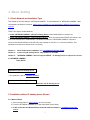
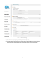
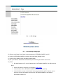
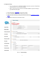
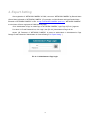
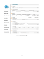
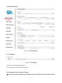
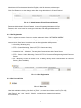
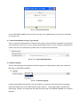
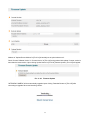
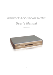
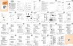
1
Veilux SVSIP-56CDNR Network and / or Analog Camera User’s Manual (IP Part) 1 Introduction The “NETWORK CAMERA” is a built-in MPEG-4 CODEC and Streaming Server. The advantages of the MPEG-4 CODEC and the built in Streaming server allows you to monitor real time image from a remote location, via Internet. “NETWORK CAMERA” server features the Sensor Input, Relay Output, and is designed to control the Pan/Tilt/Zoom functions. These functions are compatible with PLC and may be utilized to control various Electronic Appliances. The “NETWORK CAMERA” supports both Static IP and Dynamic IP, and can change Communication Port, resulting in one IP address supporting multiple. In summary, The “NETWORK CAMERA” server system provides multiple access/control options to the user. The examples of access/controls are as follows: To get SMS message through Mobile Phone and E-mail message from PC upon event. To record Event in FTP server installed in remote place or “NETWORK CAMERA”. To search / delete / down-load / replay the recorded video. To support various wireless devices such as Mobile Phone, PDA to see real time Video in Wireless Internet handset. For more information or inquiry, please contact us to the followings; Home Page : www.Veilux.net Email : [email protected] Telephone : 1-800-510-6528 Software, Server and service may be charged according to change of policy or may be stopped without prior notification. Appearance, function and specification may be changed without prior notification. Our company assumes no responsibility for visible or invisible loss resulted from changes in policy or products. 2 2. Installation and Video Check 2.1 Installation On the assumption that User PC and “NETWORK CAMERA” Sever is used under static IP, and “NETWORK CAMERA” is to be directly connected with User PC or Local Network, the installation procedure is to be ; 1) Connect “NETWORK CAMERA” and PC with LAN Cable (Cross Cable) 2) Power on "NETWORK CAMERA" ( Be sure to use Exclusive Power Adapter) 2.2 Video Check Basic network setting value of “NETWORK CAMERA” is to be ; IP Address : 192.168.1.8 Subnet Mask : 255.255.255.0 Gateway : 192.168.1.1 To connect “NETWORK CAMERA” in user‟s PC, change the setting value of PC network environment. Pic. 2―1 Network Setting of User PC 3 1) Set IP Address, Subnet Mask and Gate-way of User‟s PC with 192.168.1.50, 255.255.255.0 and 192.168.1.1 as shown on [Pic. 2-2]. Pic. 2―2 Web Browser Input 2) Run Web Browser as shown on [Pic. 2-3] and input 192.168.1.8 in URL and click “Enter”, then [Pic. 2-4] is to be shown. In case [2-4] does not appear, re-set Hardware (Reset Button (6) of Pic. 2-1) to return Network Environment of “NETWORK CAMERA” to default and run Web Browser, input 192.168.1.8 in URL line and click “Enter” . Pic. 2―3 “NETWORK CAMERA” Main Page 3) Click “Connect” Button of [Pic. 2-4]. 4 Pic. 2―4 User login 4) Input ID and Password and click on the lock [Pic. 2-5] to see the Video feed. 5) ********Please note when login remote as shown above default ID: admin & password: admin 6) User‟s Authority to see Video feed on “NETWORK CAMERA” is as follows ; Table 2-1 User ID, Password, Rights User ID User Password Rights guest guest Monitor only ptz ptz Monitor, Control of P/T/Z, Control of Relay root root All Function 7) Above [Table 2-1] is the value basically set in “NETWORK CAMERA”. Change the User Information in „General Setting‟ of „4. Expert Setting‟ after installation of “NETWORK CAMERA”. 8) Click (1) after input ID: root, Password: root in [2-5]. Pic. 2―5 ActiveX Download 9) Upon installation, Web Viewer [Pic. 2-7] appears and image of Camera is to be seen. 5 Pic. 2―6 Web Viewer 10) After checking the video feed [Pic 2-7], go to the next Chapter „3. Basic Setting‟ 11) Refer to Web Viewer Manual to see the details how to use Web Viewer. 6 3. Basic Setting 3.1 Check Network and Installation Type This Chapter is for basic setting of “NETWORK CAMERA”. To install Hardware of “NETWORK CAMERA”, basic understanding of Network is required. Please refer to Chpater 6 in case knowledge of Network Environment is required.. There is two ways to install Hardware, 1. install “NETWORK CAMERA” without IP sharing Device under Cable Modem or Leased Line, 2. install “NETWORK CAMERA” under IP sharing Device , which is required under PPPoE environment, and even under Leased Line or Cable Modem. The default IP Address of “NETWORK CAMERA” is preset to 192.168.1.8 and Subnet Mask to 255.255.255.0 and Gateway to 192.168.1.1 in ex-factory condition. This explanation is based upon default value of ex-factory. Caution 1 : Check Video before installation, on „2. Installation and Video Check‟. Caution 2 : In case using IP sharing Device, only Global IP is available. Caution 3: “NETWORK CAMERA” does not support PPPoE. IP Sharing Device is required to connect to “NETWORK CAMERA” under PPPoE. Installation without IP sharing device -> For static IP, refer to „Static IP Setup‟. -> For dynamic IP, refer to ‟ Dynamic IP Setup‟. Installation with IP sharing device -> Should set up with Static IP. Refer to „Installation with IP Sharing Device‟. 3.2 Installation without IP sharing device (Router) 3.2.1 Static IP Setup 1) After checking Video in „Video Check‟, go to the next step. 2) Connect “NETWORK CAMERA” to PC with LAN Cable (Cross Cable). 3) Cable connection and Network Setup should be same as shown in „1. Installation and Video Check‟. 7 4) Run Web Browser and input 192.168.1.8 in URL and click „Enter‟, then [Pic. 3-1] will appear. Pic. 3―1 Main Page of “NETWORK CAMERA” 5) Click „Administrator‟s Page‟ of [Pic. 3-1], then Browser shows [Pic. 3-2] Pic. 3―2 Log-in Page. Administrator Page Log-in 6) Put „admin‟ in ID and Password line, click „Login‟, then [Pic.3-3] „Administrator's Page‟ will be shown. (ID, Password of “NETWORK CAMERA” is preset as admin/admin in Administrator‟s Page. Change Administrator‟s ID and Password in General Setting of „4. Expert Setting‟ 8 Pic. 3―3 Administrator‟s Page 7) Click “Network Setting‟ in left menu on [Pic. 3-3], [Pic. 3-4] appears. 8) Click „Static IP Address‟ in „IP Setting‟ of [Pic. 3-4], and input IP Address, Subnet Mask, Default Gateway according to Network environment to connected “NETWORK CAMERA”. 9) For setting of „DNS Server‟, input DNS Address to fit with Network Environment to set. (Default Address of “NETWORK CAMERA” is DNS Address of „Dacom‟, ‟PIMA‟). Use DNS value normally set in PC. 10) DNS Address should be necessarily input. 11) In case of installation without IP sharing device under Static IP, tick on „Enable‟ of „Direct Connect‟. The „Direct Connect‟ option makes direct connection to IP set on Video connection through Web Viewer. (But not tick „Enable' in case of installation under IP Sharing Device.) 12) Click „Save‟ Button of [3-4] to save setting value. 9 Pic. 3―4 Network Setting 13) Click „Click Here‟ upon appearing of IP Change Window of [Pic. 3-5]. 14) IP Change loading Page appears as [3-6], the Main Page of changed address is connected. (May not find the main page of changed address under Cross Cable connection, but IP been changed.) 10 Pic 3―5 IP Change Pic. 3―6 IP Change loading Page 15) Remove LAN Cable (Cross Cable) connected between “NETWORK CAMERA” and PC. 16) Connect “NETWORK CAMERA” to Network with LAN Cable (Straight Cable). 17) Connect PC to Network with LAN Cable (Straight Cable).. 18) Set up IP Address, Subnet Mask and Gate way of PC according to Network environment. 19) Check Run Web Browser on PC, input IP address set in “NETWORK CAMERA” onto URL and click „Enter‟, Check if IP Setting is correct or not, referring to „Video Check‟ In case Video is seen, “NETWORK CAMERA” has been correctly set up. In case Video is not seen, check whether there may be confliction of IP in Network, and recheck the set value of Network environment of “NETWORK CAMERA”, and Network environment of User‟s PC. 11 3.2.2 Dynamic IP Setup Do not set up Dynamic IP in “NETWORK CAMERA” except direct connection of Cable Modem supporting Dynamic IP with “NETWORK CAMERA”. Reset, in case IP has not been allocated to “NETWORK CAMERA” in Dynamic IP Setting, to go to Initial Value and try again. 1) After checking Video in „Video Check‟, then go to the next step. 2) Connect “NETWORK CAMERA” and LAN Cable (Cross Cable) 3) Cable Connection and Network Setting should be done same as per„1. Installation and Video Check‟. 4) Go to Network Setting Page of Administrator‟s Page‟. Pic. 3―7 Network Setting 12 5) Click on „Dynamic IP Address‟ in „IP Setting‟. 6) Click „Save‟ Button. 7) Upon completion of setting, close the Web Page and find IP of “NETWORK CAMERA” in „IP Utility‟ program provided with Proprietary Viewer 8) If IP found, “NETWORK CAMERA” has been given IP. But in case IP is not found, do re-set of [2-1] to go to initial value because it has not been given IP, then re-start IP Setting. Once “NETWORK CAMERA” is given IP, remove LAN Cable (Cross Cable) connected between “NETWORK CAMERA” and PC. 9) Connect “NETWORK CAMERA” to Network with LAN Cable (Straight Cable). 10) Connect PC to Network with LAN Cable (Straight Cable). 11) Set IP address of PC, Subnet Mask and Gateway properly according to Network Environment. 12) Check After registration of “NETWORK CAMERA” in PIMA Server connect to “NETWORK CAMERA” by Domain Name (Server Name) allocated to “NETWORK CAMERA”. For example, run Web Browser and input Domain Name allocated to “NETWORK CAMERA” in URL. In http://ipcam.pima1.net, „“NETWORK CAMERA”‟ is to be Name of Server registered in PIMA Server by user. If the initial page is shown as [Pic. 3-8], check Video of “NETWORK CAMERA” referring to „1. Video Check‟. If Video is seen, set up is properly done. Pic. 3―8 Initial Page of “NETWORK CAMERA” 13 3.3 Installation with IP Sharing Device (Router) 1) After checking Video in „ 1. Installation and Video Check‟, then go to the next step. 2) Connect “NETWORK CAMERA” and PC with LAN Cable (Cross Cable). 3) Cable Connection and Network Setting should be done same as per „1. Installation and Video Check‟. 4) Go to Network Setting Page of Administrator‟s Page as per 4), 5), 6), 7) of „Static IP Setup‟. 5) Click „Static IP Address‟ in „IP Setting‟ of [3-9], and input IP Address, Subnet Mask, Default Gateway according to Network environment to connected “NETWORK CAMERA” to. 6) For setting of „DNS Server‟, input DNS Address to fit with Network Environment to set. (Default Address of “NETWORK CAMERA” is DNS Address of „KTF‟,‟Hanaro Communication‟). Use DNS value normally set in PC. 7) DNS Address should be input surely. In case “NETWORK CAMERA” is installed under IP Sharing Device, input local IP of Router in 2 nd DNS Server Address. 8) In case of installation without IP sharing device under Static IP, tick on „Enable‟ of „Direct Connect‟. The „Direct Connect‟ option makes direct connection to IP set on Video connection through Web Viewer. (But not tick „Enable' in case of installation under IP Sharing Device.) 9) Click „Save‟ Button of [3-9] to save the set value. 14 Pic. 3―9 Network Setting 10) Click „Click Here‟ upon appearing of IP Change Window of [Pic. 3-10]. 11) IP Change loading Page appears as [3-11], the Main Page of changed address is connected. (may not find the main page of changed address under Cross Cable connection, but IP has been changed.) 15 Pic. 3―10 IP Change 12) It is connected to IP newly set up, in 20 seconds after window of [3-11] appears. 13) Check Video of “NETWORK CAMERA” referring to „1. Video Check‟ as soon as it is connected to IP newly set up. 14) Go to Network Setting Page of Administrator‟s Page as per 4), 5), 6), 7) of Pic. 3―11 IP Change loading Page 16 „Static IP Setup‟. Pic. 3―12 Port Setting 15) Set Port in Port Setting Page of [Pic.3-12]. It is required to set each different Port for many “NETWORK CAMERA” Servers under 1 Router. 16) Click „Save‟ Button to save set value. 17) Remove LAN Cable (Cross Cable) connected between “NETWORK CAMERA” and PC. 18) Connect “NETWORK CAMERA” to Network with LAN Cable (Straight Cable). 19) Connect PC to Network with LAN Cable (Straight Cable). 20) Port-Forward the port designated to use “NETWORK CAMERA”, in IP Sharing Device. Refer to manual of IP Sharing Device for details. 21) Check 1 (local check) Run Web Browser and input IP address of “NETWORK CAMERA” in URL and click „Enter‟. If you changed Web Server Port, you must input „http://IP Address:Port Number‟. For example, If you set IP address of “NETWORK CAMERA” to 192.168.0.100 and changed Web Server port to 81, you must input Http://192.168.1.100:81. Pic. 3―13 Main Page of “NETWORK CAMERA” 17 After [Pic.3-13] appears, check Video of “NETWORK CAMERA” referring to„1. Video Check‟. 22) Check 2 (Check from outside) After registration of “NETWORK CAMERA” in PIMA Server, connect to “NETWORK CAMERA” by Domain Name (Server Name) allocated to S-151. For example, run Web Browser and input Domain Name allocated to “NETWORK CAMERA” in URL. In http://ipcam.pima1.net , „“NETWORK CAMERA”‟ is to be Name of Server registered in PIMA Server by user. If the initial page is shown, check Video of “NETWORK CAMERA” referring to „1. Video Check‟. If Video is seen, set up is properly done. 3.4 Cautions If the firewall is used for security purpose, “NETWORK CAMERA” may not work properly. In this case, open the port of “NETWORK CAMERA”, then it will work properly. The port being used by “NETWORK CAMERA” can be checked on „Port Setting‟ of „Network Setting‟ of „Administrator‟s Page‟. Port of “NETWORK CAMERA” on ex-factory is set default as follows ; Web Connection Port Authentication and Control Port: Port 9000 TCP Video Streaming Port : Port 9001 TCP Audio one-way Port : Port 9002 TCP Audio two-way Port : Port 9003 TCP : Port 80 TCP In setting user port, do not use 1504, 1508, which port is used in “NETWORK CAMERA” itself. 18 4. Expert Setting After registration of “NETWORK CAMERA” in PIMA‟, connect to “NETWORK CAMERA” by Domain Name (Server Name) allocated to “NETWORK CAMERA”. (For example, run Web Browser and input Domain Name allocated to “NETWORK CAMERA” in URL. In http://”NETWORK CAMERA”.pima1.net, „“NETWORK CAMERA”‟ is to be Name of Server registered in PIMA Server by user) Click „Administrator‟s Page‟ on Initial Page of “NETWORK CAMERA”, login Page of [Pic.4-1] appears. Put „admin‟ in ID and Password line, click „Login‟, then [Pic.4-2] „Administrator's Page‟ will be shown. (ID, Password of “NETWORK CAMERA” is preset as admin/admin in Administrator‟s Page. Change ID and Password of Administrator in General Setting of „4. Expert Setting‟. ) Pic. 4―1 Administrator‟s Page Login 19 Pic. 4―2 Administrator‟s Page 20 4.1 General Setting Pic. 4―3 General Setting 4.1.1 Title Setting Pic. 4―4 Title Setting Server title is to be English without space. Click „Save‟ Button to save title after input name. 4.1.2 Administrator‟s ID and Password Change ※ Cautions: Change Administrator‟s ID and Password and do not disclose the information to others. 21 Administrator‟s ID and Password should be English, within 20 characters, without space. Click „Save‟ Button to save the changed value after change Administrator‟s ID and Password. Pic. 4―5 Administrator‟s ID and Password Change Remember Administrator‟s ID and Password. In case of forgetting Administrator‟s ID and Password, click „reset‟ button for returning to initial value, and change Administrator‟s ID and Password. 4.1.3 User Registration This is to register an account of user who monitor and control Video of “NETWORK CAMERA”. Administrator‟s ID and Password should be English, within 20 characters, without space. Allow the authority to users and click „Save‟ button. A maximum user to allow registration is 100 persons. View Only: Monitoring only. PTZ + Control: Monitoring, Control of P/T/Z of Camera and Relay. Audio: Monitoring, and hearing Audio of Server. Interactive Audio : : Monitoring, Two-way Audio Communication with Camera Server PTZ + Control + Audio: Monitoring, Control of P/T/Z of Camera and Relay, Hearing Audio of Camera Server. All : Monitoring, Control of Camera P/T/Z and Relay, two-way Audio Communication with Camera Server, (Preset available) Pic. 4―6 User Registration 4.1.4 User List and Delete Pic. 4―7 User List User list is available on clicking „List Users‟ on [Pic.4-7], to check list and delete user ID in [Pic.4-8]. User ID „guest‟, „ptz‟, „audio‟, „Iaudio‟, „PCAudio‟, „root‟ has be pre-registered as basic user ID on ex-factory. 22 Pic. 4―8 User List 4.1.5 Skip Login (Automatic Monitoring) Pic. 4―9 Skip Login Check on „Skip Login‟ of [Pic.4-9], and click „Connect ID‟ and save the value, then Web Viewer will be appeared automatically and Video of Camera can be seen upon connection to Home Page of “NETWORK CAMERA”. Save „Connect ID‟ according to user authority. If you don‟t check on „Skip Login‟, it is available to connect to “NETWORK CAMERA” Home Page but you can not see the Video feed from the camera. In this case, input user ID and Password for connection to see the Video feed from the Camera. 4.1.6 Time Zone Setting This is to set Time zone of location where “NETWORK CAMERA” is to be installed, to set up local time in case of monitoring from different time zone area. Select one of time zone in „Set Time Zone‟ and save. Pic. 4―10 Time Zone Click „Display‟ in [4-10] to see current time set in “NETWORK CAMERA”. 23 Pic. 4―11 Current Time View In case “NETWORK CAMERA” does not keep correct time, click „Update‟ Button to get new time information from set time zone. 4.1.7 Set Download Route of Plug-in Type ActiveX This is to set how to download Active X of Web Viewer, locally or from outer Server designated. In case setting as local download, it has a merit to use in private network without Internet. In case of setting as download from outside, it has a merit to download the updated Active X of Web Viewer automatically. Pic. 4―12 Plug-in Download Route 4.1.8 Select Language This is to select language to be displayed in all Web Pages such as Administrator‟s Page, Web Viewer and Main Page of “NETWORK CAMERA”. Pic. 4―13 Select Language It supports both English and Japanese. Click „Save‟ Button to save the set value after select the Language. Input ID and Password to connect Administrator‟s Page, and go to „Home Page Update‟->‟Default Home Page Setting‟->‟Default‟, and change the main Page and Login Page of “NETWORK CAMERA” to the selected language. 24 4.2 Network Setting This is to set Network to use “NETWORK CAMERA”. Set Network to fit user‟s network environment in „3. Basic Setting‟ Change Network information to fit environment for “NETWORK CAMERA” to be installed in. 4.3 Video & Audio Setting Pic. 4―14 Video and Audio Setting 4.3.1 Video Setting Select and tick on the Channel to use, input Video format (NTSC or PAL), Resolution, Bit rate, Frame rate and Key frame. 25 Pic. 4―15 Video Setting If you want to factory reset, click the ‘default’ button. [Pic4-16] Pic. 4―16 Video Setting 4.3.2 Audio Setting For one way audio communication, check „Audio Enable (Server -> Client)‟ of [Pic.4-17], And for two way audio communication, check „Interactive Audio Enable (Server -> Client)‟. In case Audio is not used , check „Disable‟. Then click „Save‟ to save Set value. For adjustment of audio volume, select in „Audio Volume Setting‟ and save in [Pic.4-17]. Pic. 4―17 Audio and Volume Setting 26 4.4 Color Setting This is to adjust color of channel. Pic. 4―17 Display Color Setting Upon adjustment of color on [Pic.4-18], then click „Save‟ to save the setting value. In case to return to default value, click „Default‟. Even in this case, it is required to click „Save‟ Button for saving the setting value. 4.5 Alarm Setting 4.5.1 Alarm Event Setting To get Alarm Service on “NETWORK CAMERA”, go to „Administrator's Page‟‟Alarm Setting‟ and tick „Enable‟ in „Alarm‟. 27 Pic. 4―18 Alarm Setting Designate condition to drive Event in „Alarm Condition‟, such as Sensor Event, Motion detection Event or Sensor + Motion detection Event, If Sensor Event is selected, do Sensor setting in „4.6 DIO Setting‟. Sensitivity: To select the sensitivity of motion detection. The larger number represents higher sensitivity to motion. Upon Event situation after setting on ‟Enable‟ in „Alarm‟ of „Alarm Event‟, Event is to be transmitted to user‟s Viewer and inform detection of Event, with flickering on screen and alarm sound. To use SMS Service and E-mail transmitting Event to Alarm Server, go „Alarm Style‟-> „Alarm Server‟ and input Domain Name of Alarm Server. To send the recorded video to FTP Server upon alarm event, go „Alarm Style‟-> „FTP‟ and input FTP Server Address, Directory, User IP and Password, FTP Directory (mandatory). Make user‟s directory in FTP root of User‟s FTP Server to get recorded files to be transmitted. Click „Save‟ Button to save setting value. In case of setting to send Event to Alarm Server, register “NETWORK CAMERA” in PIMA Server to use Alarm Server 4.5.2 Alarm Event Test Click „Test‟ of [Pic 4-19], “NETWORK CAMERA” will work as if Alarm has happened. In case „Alarm Style - >‟Alarm Server‟ is selected, Event is to be notified to Alarm Server and is to recorded into the recorded file (10 seconds before and 20 seconds after Event), and to be sent to Alarm Server. In case user FTP Server is selected to use, the recorded file (10 seconds before and 20 seconds after Event) 28 is to be saved in FTP Server. It may take some time for Alarm Message to get to user‟s Mobile Phone or by E-mail, in some cases. If “NETWORK CAMERA” has been registered in PIMA Server, it is available to check the details of Event and also change the Alarm Message of E-mail and Mobile Phone to be sent upon Event, in Alarm Server Homepage (.pima1.net). 4.6 DIO Setting Pic. 4―19 DIO Setting Tick on sensor to use and select type of sensor to use. Sensor Type : designate type of sensor, NC, NO. Designate name of sensor to use. 4 conditions are selectable for Relay. Relay name is to be input. Disable Remote Control : to control Relay through Internet using Viewer Local Control Remote & Local Control: Control Relay through Internet using Viewer. To be ON : not to use Relay : Relay is on during „Duration‟ time upon Event on Sensor, and then is to be off. during „Duration‟ time upon event on Sensor, then to be OFF. It‟s available to designate name on Relay to use. 29 4.7 RS232C Setting Pic. 4―20 RS232 Setting It is available to select P/T/Z module supported or P/T/Z Integrated Camera. Models of Camera supported by “NETWORK CAMERA” RS232C Bypass Control To use RS232 Bypass, set as „RS232 BYPASS‟. User‟s data is to be sent thought RS232 of “NETWORK CAMERA”. Example) * Transmit Data : 0x6F,0x70,0x,65,0x6E BYB9600=1Aopen * Transmit Data : 0x6F,0x70,0x,65,0x6E BYB9600=1B6F70656E Explanation: ->„BYB‟ : Fixed (not changeable) ->‟9600‟ is baud rate(2400,19200,38400….) ->‟=‟ : fixed (not changeable) ->‟1‟ : type(1: 8bits No parity 1 stop bit 2: 7bits Even parity 1 stop bit 3: 7bits Odd parity 1 stop bit) ->‟B‟ : Type of date to transmit(A:ASCII, B:Binary) ->‟ 6F70656E‟ : Data to transmit 30 4.8 Preset Setting ⑤ ③ ① ④ ② Pic. 4―22 Preset Setting It is available to pre-set Pan/Tilt/Zoom Cameras. Preset Setting is available up to 20, but may be less than 20 for some model of Camera. (1): Select Channel; to select the channel to preset. (2): Preset No. : To select the Preset Number to set up. (3): Preset Name: to input Name of Preset to set up, Preset Name is be 30 character, without space and special characters. (4): Preset SET; „SET‟ button is to set the current coordinate as preset location with name recorded by user. In three seconds after pushing „SET‟ button, the Preset coordinate is to be set. Do not move Camera during the time (about three seconds). (5): Preset Move: to move to the selected preset number. (6): Adjustment of Pan/Tilt/Zoom/Speed/Focus: to move to the location to preset by adjusting Pan/Tilt/Zoom/Focus. 31 4.9 Homepage Update Pic. 4―23 Homepage Update Homepage Update function is for user to upload the main page of “NETWORK CAMERA” onto user‟s Homepage. User‟s Homepage is composed of 3 files as like index.html, top.htm, main.htm. The file for user to use is main.htm. After making Web Page (main.htm) and save it as file name of main.htm, upload by the function of „Homepage Update‟, then manin.htm page is to be the 1st main page of “NETWORK CAMERA”. (Image file is not uploaded in “NETWORK CAMERA”.) User Homepage cannot exceed 300Kbyte. If user wants to re-make user‟s homepage into Homepage provided complimentarily, click „Default Home Page Upload‟. 4. 10 Firmware Update 4.10.1 Remote Upgrade In case firmware is upgraded in the near future, the upgrade is only supported via Internet. Remote Upgrade 32 Pic. 4―21 Firmware Update Address of „Update Server Address‟ in [Pic.4-24] is basically set as „pima1telecom.net‟. Check „Current Software Version‟ in „Current Version‟ of [Pic.4-24] and go ahead with update if current version is lower than the latest version. Upon clicking „Update‟ button in [Pic.4-24] „Remote Update‟, [Pic.4-25] will appear. Pic. 4―22 Firmware Update “NETWORK CAMERA” will be automatically upgraded upon clicking „Download‟ button of [Pic.4-25] after connecting to Upgrade Server and checking version. 33 Pic. 4―23 Firmware Download „Downloading‟ message will be shown until completion of Update as [Pic.4-26] (it may take time according to Network situation). Upon completion of upgrade, there appears message showing upgrade result. [Pic. 4-27] is the message showing that upgrade has been correctly done. Click „Restart‟ in „System Restart‟ to restart System of “NETWORK CAMERA”. Pic. 4―24 Completion of Upgrade If [Pic. 4-28] is displayed as below, it means that “NETWORK CAMERA” has been upgraded to the latest Version, there is no need to update any more. Pic. 4―25 Check of Upgrade Version If user found [Pic. 4-29], there is a error in connection to Upgrade Server, re-check Internet Connection or recheck DNS Server Address in „3. Basic Setting‟ and try to upgrade again. If user keep finding [Pic.4-29] or cannot upgrade, contact head office or local agent. Pic. 4―26 Upgrade Server Connection Error 34 4.10.2 System Re-booting This is the function to re-boot Inner Software of “NETWORK CAMERA”. Click „Restart‟ on „System Restart‟ to reboot all inner program of “NETWORK CAMERA”. 4.11 Periodic Capture Image Transmission system rebooting This function is useful on V4.1 over. Pic 4-30 JPEG Capture Transmission Pic 4-29 /28 upgraded server connection error. Schedule: Setting the available time to capture Resolution: Setting the capture image size Interval: Setting the periodic time to capture Enable: Must be checked to operate the capture & transmission function Server address: Setting the name of target FTP server address Directory: input the target directory name which is the under directory of root directory of FTP server User ID, password: Input the ID & password to access FTP server Base name: Setting the name of captured & saved image Additional file name: the options of setting file name None: useful only Base name Date-Time: Date & time is added after basic file name like as: image_20083011_111223.jpg Sequence Number: Base name + sequential number like as : image_1.jpg, image_2.jpg Additional Caption: Able to input the caption on the captured image 35