1
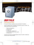
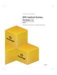
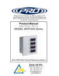
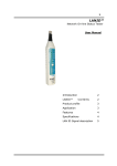
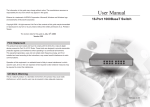
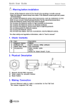
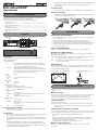
All ports support autonegotiation. The optimal duplex mode (full duplex or
half duplex) and transfer speed (1000, 100, or 10 Mbps) are selected
automatically.
TM
BS-GU2008P
4. Uplink ports
User Manual
Connect other hubs or switches to these ports. These ports don't support PoE.
5. Power connector
Package Contents
Connect the included AC adapter to this connector. Secure the AC adapter
cable with the included cable retainer.
The package contains the items shown below. If any items are missing, please
contact the dealer where you purchased the BS-GU2008P.
The appearance of the BS-GU2008P may vary from the illustration.
•
•
•
•
•
•
•
②
①
Switch (main unit) ........................................................................................................................ 1
AC adapter....................................................................................................................................... 1
Power cable retainer band......................................................................................................... 1
Rubber feet .................................................................................................................................... 4
Serial number stickers ............................................................................................................... 2
User manual (this document)................................................................................................... 1
Warranty .......................................................................................................................................... 1
Layout
1. Indicators
3. PoE ports
Installation
Precautions for Installation
4. Uplink ports
2. Loop prevention switch
③
• Do not install the device in an unstable location such as on an unsteady table or
an inclined surface.
• Do not place another hub or object that generates heat on this unit.
• Please route all cables properly to prevent people from tripping over them.
• Ensure the air vents on the product are not blocked by other equipment or walls.
• Only use the AC adapter included with the product. Using other AC adapters
may result in damage or fire.
5. Power connector
Floor or Shelf Mounting
Attach the supplied rubber feet to the bottom corners of the unit before use.
Mounting to a Metal Surface
To mount to a metal surface, such as the side of a steel desk, use the "BS-MGK-A
Magnet Kit" (sold separately).
PoE Limit (Orange)
PoE is supplying more than 30 watts of power to all devices. For
On:
temperatures above 40℃ (104°F), don't connect devices that
draw more than 30 watts of PoE power total.
Blinking:
PoE power has been disabled to some ports because the
maximum 50 watts of PoE power was exceeded. PoE power was
disabled for ports in order of descending port number until the
total PoE output power was less than 50 watts.
Off:
Normal
Loop (Red)
Blinking:
Off:
Loop blocked (blinks once per second)
Normal
Power (Green)
On:
Off:
Power on
Power off
PoE (Green or Orange)
On (Green): PoE power is available
On (Orange): Overcurrent or excessive power draw
Off:
PoE power is disabled
1000 Mbps (Green)
On:
1000 Mbps Link
Blinking:
If a loop is blocked, the LED for the blocked port blinks once
per second.
Off:
100 Mbps or 10 Mbps Link, No Link
Link/Act (Green)
On:
Link established
Blinking:
Data transfer
If a loop is blocked, the LED for the blocked port blinks once
per second.
Off:
Link not established
2. Loop prevention switch
This switches loop prevention on and off. After flipping the switch, disconnect
and reconnect the power cable.
3. PoE ports
These Ethernet ports support PoE. Connect devices that need Ethernet power
to these ports. Each port can supply up to 15.4 watts.
The maximum total supply for all 6 ports varies according to the operating
temperature. If it is below 40℃ (104°F), 50 watts. If it is above 40℃ (104°F),
30 watts.
Connect Ethernet devices to the switch in ascending order of port
number. If the maximum total power for PoE exceeds 50 watts, power to
ports will be disabled in descending order by port number until the total
output power for PoE is below 50 watts.
Caution: Do not put floppy discs, magnetic cards, or other magnetic storage media
near magnets. Doing so may delete or corrupt data.
Note:
If the switch is secured by the magnet alone, it should be no more than 75
cm (29.5 in) from the floor.
Wall Mounting
To mount the unit to a wall, use 2 screws (not included) with the dimensions shown
below. Install the screws 113 mm (4.4 in) apart and slide the mounting holes in the
base of the BS-GU2008P over them.
Mounting holes
Magnet mounting holes
Use screws where this section is
2 mm or less.
2
3
Indicators are located on the front panel of the product. The functions of each
indicator are shown below.
φ6
1. Indicators
Bottom
Loop Prevention
This unit can detect and prevent network loops that can cause interference in the
network.
What is a Loop?
If both ends of an Ethernet cable are connected to the same hub, or when multiple
connections exist between two hubs, data may be sent in a loop around the
network, wasting network capacity and never getting to its destination. This
continuously circulating data may interfere with other network communication.
Loop Prevention
・Off: Loops are not blocked.
・On: If a network loop is detected, the port is blocked until the loop is fixed. Also,
the loop, link/act, and 1000 Mbps (if active) LEDs for the blocked port blink
once per second.
Turning Loop Prevention On and Off
1. Use the switch on the front of the BS-GU2008P to turn loop prevention on or off.
2. After changing the switch position, disconnect and reconnect the power cable. The
change will take effect when the BS-GU2008P has rebooted.
Notes:
・While loop prevention is enabled, the BS-GU2008P will send a loop detection
packet through the network every two seconds. If these packets disrupt your
network in any way, disable loop prevention.
・Loop prevention cannot detect or block all types of loops.
When a Loop is Detected
Reconnect your Ethernet cabling, making sure that there are no redundant
connections.
Specifications
Check Buffalo’s website (www.buffalotech.com) or the product catalog for
information about the latest products or compatible models.
Standards
IEEE 802.3ab (1000 BASE-T)
IEEE 802.3u (100 BASE-TX)
IEEE 802.3 (10 BASE-T)
IEEE 802.3af (PoE)
Flow Control
IEEE802.3x (when operating at full duplex)
Back pressure (when operating at half duplex)
Ports
PoE ports: 6
Uplink ports: 2
All ports support Auto-MDIX.
Compatible Cables
(*) (**)
1000 BASE-T: Enhanced category 5 or higher UTP
cables
100 BASE-TX: Category 5 or higher UTP/STP cables
10 BASE-T: Category 3 or higher UTP/STP cables
PoE:
Category 5 or higher UTP/STP cables
Connector
RJ-45 8-pin connector (shielded)
Power
AC 100-240 V 50/60 Hz
Power Consumption
Max. 60 W
External Dimensions
200 x 161 x 41 mm; 7.9” x 6.3” x 1.6”
(excluding protruding parts)
Weight
1 kg (2.2 lb.)
Operating
Environment
Operating temperature
0–50℃ (32-122°F) with PoE supplying less than
30 watts
0–40℃ (32-104°F) with PoE supplying more than
30 watts
Operating humidity
10–85% (no condensation)
Acquired Standards
VCCI Class B, FCC Class B, Canada IC Class B, UL
Transmission
Speeds
1000 Mbps (1000 BASE-T)
100 Mbps (100 BASE-TX)
10 Mbps (10 BASE-T)
Switching Method
Store and forward
Jumbo Frames
Up to 9,216 bytes (including 14 byte header + 4 byte
FCS)
Transfer Encryption
Method
8B1Q4/4D-PAM5(1000 BASE-T)
4B5B/MLT-3(100 BASE-TX)
Manchester encoding(10 BASE-T)
Access Method
CSMA/CD
Data Transfer Speed
(Throughput)
1,488,095 packets/second (1000 BASE-T)
148,810 packets/second (100 BASE-TX)
14,881 packets/second (10 BASE-T)
MAC Address Table
8,000 (Self learning)
Buffer Memory
256 KBytes
Aging Time
Approx. 300 seconds
Other
Loop prevention
Power saving (***)
Federal Communication Commission Interference Statement
This equipment has been tested and found to comply with the limits for a Class
B digital device, pursuant to Part 15 of the FCC Rules. These limits are designed
to provide reasonable protection against harmful interference in a residential
installation.
This equipment generates, uses and can radiate radio frequency energy and, if
not installed and used in accordance with the instructions, may cause harmful
interference to radio communications. However, there is no guarantee that
interference will not occur in a particular installation.
If this equipment does cause harmful interference to radio or television
reception, which can be determined by turning the equipment off and on, the
user is encouraged to try to correct the interference by one or more of the
following measures:
- Reorient or relocate the receiving antenna.
- Increase the separation between the equipment and receiver.
- Connect the equipment into an outlet on a circuit different from that to
which the receiver is connected.
- Consult the dealer or an experienced radio/TV technician for help.
This device complies with Part 15 of the FCC Rules. Operation is subject to the
following two conditions: (1) This device may not cause harmful interference,
and (2) this device must accept any interference received, including interference that may cause undesired operation.
* This unit automatically detects and adjusts for straight or crossover Ethernet
cables, so either type of cable may be used.
** Site-terminated Ethernet cables are not recommended. Always use preassembled
cables.
***This function automatically recognizes the port link status and LAN cable length
and adjusts the operating power accordingly.
Troubleshooting
If you are unable to connect to a network, check the following.
• Is the AC adapter connected correctly? Also, is the AC adapter plugged into an
outlet or surge protector?
• Is the LAN cable connected correctly? Are any cables disconnected or broken?
• Is the link/act LED on*?
*If the link/act LED is off, manually set the communication mode of the
connected hub or LAN adapter to 100M half-duplex or 10M half-duplex.
2014 - 5