1
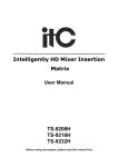
W5200E01-M3 User’s
Guide
Version 1.0
www.wiznet.co.kr
©Copyright 2011 WIZnet Co., Inc. All rights reserved.
1
Introduction ............................................................................................ 4
2
Specification ........................................................................................... 5
3
W5200E01-M3 Block Diagram ........................................................................ 5
4
Hardware Layout ...................................................................................... 6
5
Expansion Port Interface ............................................................................. 7
6
Development environment ........................................................................... 8
6.1
IDE ............................................................................................ 8
6.2
Install Flash loader Demonstrator ....................................................... 8
6.3
USB-to-UART interface IC Driver ......................................................... 8
7
W5200 SPI .............................................................................................. 10
8
W5200 Memory Map .................................................................................. 13
9
Reference Firmware ................................................................................. 14
10
9.1
W5200 Socket API ......................................................................... 15
9.2
Firmware Structure ....................................................................... 17
9.3
Firmware Functions ....................................................................... 18
9.4
Firmware Build and Upload .............................................................. 19
9.4.1
Build – IAR Embedded Workbench IDE ................................................. 19
9.4.2
Upload – Flash Loader Demonstrator ................................................... 20
Application Demonstration .......................................................................... 23
10.1
Flow of Demonstration ................................................................... 23
10.2
Ping TEST ................................................................................... 24
10.2.1 Network configuration for TEST PC .................................................... 24
10.2.2 Ping Test at Command Prompt .......................................................... 24
10.3
App. TEST – Loopback TEST .............................................................. 25
11
Physical Specification ................................................................................ 27
12
Schematic .............................................................................................. 28
© Copyright 2011 WIZnet Co., Inc. All rights reserved.
2
W5200E01-M3 User’s Guide
Table of Contents
Figure 1 W5200E01-M3 Block Diagram....................................................................................................5
Figure 2 W5200E01-M3 Layout ....................................................................................................................6
Figure 3 Download Flash loader demonstrator .....................................................................................8
Figure 4 Currently Supported VCP Drivers (3MAR2010) ...................................................................9
Figure 5 W5200 SPI Interface..................................................................................................................... 10
Figure 6 W5200 Memory Map .................................................................................................................. 13
Figure 7 TCP SERVER /CLIENT.................................................................................................................... 14
Figure 8 Compile on IAR Embedded Workbench IDE ..................................................................... 19
Figure 9 Flow Chat of Demonstration .................................................................................................... 23
Figure 10 W5200E01-M3 Board Dimension ......................................................................................... 27
© Copyright 2011 WIZnet Co., Inc. All rights reserved.
3
W5200E01-M3 User’s Guide
Table of Figures
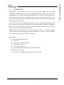
Introduction
W5200E01-M3 is the evaluation board for testing iEthernet W5200 and prototyping
development. W5200E01-M3 is composed of a STM32F103C8 based on ARM Cortex M3 CPU core,
a W5200 which acts as Hardwired TCP/IP embedded Ethernet controller, and a FT232R which
acts as USB-to-UART interface IC. W5200 has been proven in various fields to work as a fully
hardwired TCP/IP implemented chip that processes various protocols such as TCP, UDP, IPv4,
ICMP, ARP, IGMP, PPPoE, and etc.
Cortex-M3 can be used to test W5200’s performance, and the surrounding peripherals can be
used to implement various Ethernet Applications. The USB-to-UART interface IC in W5200E01M3 can be used for UART communication. And the extension pin header (total of 40 pins)
allows the user for easy connection and testing.
W5200E01-M3 can provide simple example codes based on ANSI C to implement various
internet application programs based on W5200. W5200 can be used as a small embedded
deice in Power down mode to save power consumption.
Main features;
W5200 Hardwired TCP/IPcore.
Cortex-M3.
RJ-45 which is integrated transformer.
USB-to-UART interface IC.
40 pin expanded header.
2 user LEDs, 2 Serial TX/RX LEDs ,1 POWER Indicate LED
Mode S/W, Reset S/W
Power source : USB BUS power (500mA), External VIN (5V)
© Copyright 2011 WIZnet Co., Inc. All rights reserved.
4
W5200E01-M3 User’s Guide
1
Specification
Table 1 List of Items Contained in the EVB
Item
Description
Remark
TCP/IP core
W5200
Hardwired TCP/IP core
MCU
Cortex-M3 MCU
STM32F103C8
USB-to-Serial Converter
On board USB-to-UART interface IC,
USB bus power
Ethernet
On board RJ-45 which is integrated transformer
LED
User LED 2Ea
Serial Status LED 2Ea
Button
Reset Switch 1Ea
Program Enable Switch 1Ea
Expansion Port
MCU port expansion
-
PCB
3
in 2.54mm Pitch Pin-Header Hole
28mm * 52mm Size
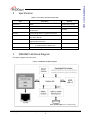
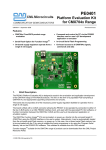
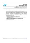
W5200E01-M3 Block Diagram
The Block diagram is shown below.
Figure 1 W5200E01-M3 Block Diagram
© Copyright 2011 WIZnet Co., Inc. All rights reserved.
5
FT232RQ
-
W5200E01-M3 User’s Guide
2
W5200E01-M3 User’s Guide
4
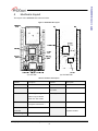
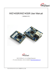
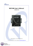
Hardware Layout
The layout of the W5200E01-M3 is shown below.
Figure 2 W5200E01-M3 Layout
(a) SILK TOP
(b) SILK BOTTOM
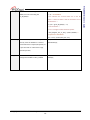
Table 2 Hardware Description
Symbols
Description
Symbols
Description
W5200
Hardwired TCP/IP Core
STM32F103C8
Cortex-M3 MCU
RESET S/W
Reset Switch
User LED1 /
User LED 2Ea
User LED2
PROG S/W
Enable Programming Switch
FT232RQ
USB-to-UART Interface IC
POWER LED
POWER Indicate LED
J1 / J2
20 Pin 2.54mm Pitch
- PROG: Program Enable
- RUN: User APP. Enable
Ethernet Port
RJ-45
( integrated transformer )
Serial TXD /
Serial status LED 2Ea
Serial RXD
Mini USB B-type
Expanded Headers
USB Connector
© Copyright 2011 WIZnet Co., Inc. All rights reserved.
6
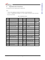
Expansion Port Interface
The expansion port has 2.54mm Pitch Pin-Header Hole.
Note.
1. Some of the expanded pin headers are shared by on board peripherals.
2. Refer to STM32F103C8’s datasheet for more detailed information about alternative
functions of pin header
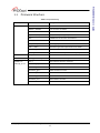
Table 3 Expanded pin header
J1
Alternative Functions
Shared by
J2
Alternative Functions
Shared by
PA0
WKUP/UASRT2_CTS
LED3
nRESET
-
-
PA1
USART2_RTS/ADC12_IN1
LED4
PB1
ADC12_IN9/TIM3_CH4
-
PA2
USART2_TX/ADC12_IN2
-
PB2
-
BOOT1
PA3
USART2_RX/ADC12_IN3
-
PB3
-
-
PA4
SPI1_NSS/USART2_CK
nSS1
PB4
-
-
PA5
SPI1_SCK/ADC12_IN5
SCLK1
PB5
I2C1_SMBAI
-
PA6
SPI1_MISO/ADC12_IN6
MISO1
PB6
I2C1_SCL/TIM4_CH1
-
PA7
SPI1_MOSI/ADC12_IN7
MOSI1
PB7
I2C1_SDA/TIM4_CH2
-
3V3D
-
-
3V3D
-
-
GND
-
-
GND
-
-
GND
-
-
GND
-
-
PA8
USART1_CK/TIM1_CH1
TXD1
PB10
I2C2_SCL/USART3_TX
-
PA9
UART1_TX/TIM1_CH2
RXD1
PB11
I2C2_SDA/USAART3_RX
-
PA10
UART1_RX/TIM1_CH3
-
PB12
SPI2_NSS/I2C2_SMBAI
-
PA11
UART1_CTS/CANRX/
-
PB13
SPI2_SCK/USART3_CTS
-
PA12
UART1_RTS/CANTX
-
PB14
SPI2_MISO/USART3_RTS
-
PA13
-
-
PB15
SPI2_MISO/TIM1_CH3N
-
PA14
-
-
PC13
TAMPER-RTC
-
PA15
-
-
PC14
OSC32_IN
-
VIN_5V
External VIN (5V)
-
PC15
OSC32_OUT
-
© Copyright 2011 WIZnet Co., Inc. All rights reserved.
7
W5200E01-M3 User’s Guide
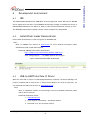
5
Development environment
IDE
6.1
The IAR Embedded Workbench for ARM IDE is currently supported. (Other IDE tools for ARM IDE
will be supported as like Keil.) The W5200E01-M3 software package is released the version of
IAR Embedded Workbench for ARM 5.41. Refer to IAR’s own documentation on how to use it.
The W5200E01-M3 software package contains various examples for using W5200
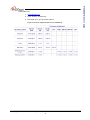
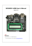
Install Flash loader Demonstrator
6.2
Flash Loader demonstrator is used to program for W5200E01-M3.
Note:
Refer to UM0462 User manual at www.st.com for more detailed information about
STM32F103xx Flash Loader demonstrator
-
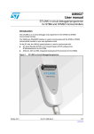
Download: UM0462 Flash loader demonstrator
http://www.st.com/internet/mcu/product/216817.jsp
Click “Design Support” -> SW DEMOS (Bottom end of page)
Figure 3 Download Flash loader demonstrator
USB-to-UART interface IC Driver
6.3
When the mini-USB is connect to USB-equipped Windows computer, the Device Manager will
properly installed USB-to-Serial driver. If USB-to-Serial adaptor not works as expected, you
can download the USB-to-Serial driver at www.ftdichip.com.
Note:
Refer to Installation Guides at www.fuducguo.com more detailed information about
USB-to-Serial converter.
-
Download Installation Guides:
1. www.fidichip.com
2. Click “Support->Documents-> Installation Guides”
3. Download up to your operation system.
© Copyright 2011 WIZnet Co., Inc. All rights reserved.
8
W5200E01-M3 User’s Guide
6
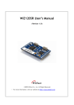
Download Driver
1. www.fidichip.com
2. Click “Drivers->VCP Drivers”
3. Download up to your operation system.
Figure 4 Currently Supported VCP Drivers (3MAR2010)
© Copyright 2011 WIZnet Co., Inc. All rights reserved.
9
W5200E01-M3 User’s Guide
-
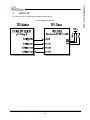
W5200 SPI
The SPI Interface of ST23F103 with W5200 is shown below.
Figure 5 W5200 SPI Interface
© Copyright 2011 WIZnet Co., Inc. All rights reserved.
10
W5200E01-M3 User’s Guide
7
SPI burst mode, and how to use it.
Code 1 Pseudo code for Read with SPI interface
#define data_read_command
uint16 addr;
0x00
//address : 16bits
int16 data_len;
uint8 data_buf[];
//data_length :15bits
// array for data
SpiSendData();
//send data from MCU to W5200
SpiRecvData();
//Receive data from W5200 to MCU
/* Pseudo Code for Read data of 8bit per packet */
{
ISR_DISABLE();
CSoff();
// Interrupt Service Routine disable
// CS=0, SPI start
//SpiSendData
SpiSendData(((addr+idx) & 0xFF00) >> 8);
SpiSendData((addr+idx) & 0x00FF);
//Address byte 1
//Address byte 2
// data write command + data length upper 7bits
SpiSendData((data_read_command | ((data_len & 0x7F00) >> 8)));
// data length bottom 8bits
SpiSendData((data_len & 0x00FF));
SpiSendData(0);
//dummy data
data_buf[idx] = SpiRecvData(idx);
CSon();
//READ data
// CS=1, SPI end
ISR_ENABLE();// Interrupt Service Routine disable
}
© Copyright 2011 WIZnet Co., Inc. All rights reserved.
11
W5200E01-M3 User’s Guide
A pseudo code for read/write with SPI is shown below. Check the W5200 documentation for
#define data_write_command
uint16 addr;
0x80
//address : 16bits
int16 data_len;
uint8 data_buf[];
//data_length :15bits
// array for data
SpiSendData();
//send data from MCU to W5200
SpiRecvData();
//Receive data from W5200 to MCU
/* Pseudo Code for Read data of 8bit per packet */
{
SpiSendData();
ISR_DISABLE();
CSoff();
//send data from MCU to W5200
// Interrupt Service Routine disable
// CS=0, SPI start
SpiSendData(((addr+idx) & 0xFF00) >> 8);
SpiSendData((addr+idx) & 0x00FF);
//Address byte 1
//Address byte 2
// data write command + data length upper 7bits
SpiSendData((data_write_command | ((data_len & 0x7F00) >> 8)));
// data length bottom 8bits
SpiSendData((data_len & 0x00FF));
SpiSendData(data_buf[idx]);
CSon();
// CS=1, SPI end
IINCHIP_ISR_ENABLE();
// Interrupt Service Routine disable
}
© Copyright 2011 WIZnet Co., Inc. All rights reserved.
12
W5200E01-M3 User’s Guide
Code 2 Pseudo code for Write with SPI interface
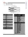
W5200 Memory Map
Refer to W5200 Datasheet for more detail information.
Figure 6 W5200 Memory Map
Table 4 W5200 Memory
Start Address
0x0000
0x0001
0x0005
0x0009
0x000F
0x0013
0x0015
0x0016
0x0017
Register
Mode (MR)
Gateway Address
(GAR[0-1])
Subnet mask Address
(SUBR[0-1])
Source Hardware Address
(SHAR[0-5])
Source IP Address
(SIPR[0-3])
Reserved
Interrupt (IR)
Socket Interrupt Mask (IMR)
0x0020
0x0028
Retry Time
(RTR[0-1])
Retry Count (RCR)
Reserved
Authentication Type in PPPoE
(PATR[0-1])
Authentication Algorithm in PPPoE
(PPPALGO)
Reserved
PPP LCP Request Timer (PTIMER)
0x0029
PPP LCP Magic number (PMAGIC)
0x0030
Interrupt Low Level Timer
(INTLEVEL[0-1])
Reserved
Socket Interrupt (IR2)
PHY Status (PSTATUS)
Interrupt Mask (IMR2)
0x0019
0x001A
0x001C
0x001E
0x0032
0x0034
0x0035
0x0036
n is socket number ( 0, 1, 2, 3, 4, 5, 6, 7 )
© Copyright 2011 WIZnet Co., Inc. All rights reserved.
13
W5200E01-M3 User’s Guide
8
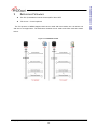
Reference Firmware
The TCP (Transmission Control Protocol) RFC 793 of IETF
TCP Server / Client Loopback
The TCP protocol of W5200 supports both server mode and client mode, user can select one
and use for its application. The difference between server mode and client mode are shown
below.
Figure 7 TCP SERVER /CLIENT
© Copyright 2011 WIZnet Co., Inc. All rights reserved.
14
W5200E01-M3 User’s Guide
9
W5200 Socket API
Table 5 W5200 Socket API
Function
Description
Example code
socket()
To create the SOCKET n (the n-1 th
Method 1 : server mode
SOCKET), use the socket() function to set
/* sets Protocol Number */
the SOCKET number, protocol, port
s = 0; // set SOCKET 0 (From 0 to 7)
number, and flag.
/* OPEN SOCKET 0 */
socket(s, Sn_MR_TCP, port, mode);
while(getSn_SR(s) != SOCK_INIT);
Method 2 : client mode
/* sets Protocol Number */
s = 0; // set SOCKET 0
/* sets port number */
any_port = 1000;
/* OPEN SOCKET 0 */
socket(s, Sn_MR_TCP, any_port++, mode);
while(getSn_SR(s) != SOCK_INIT);
listien()
The LISTEN step is only used during
s = 0; // set SOCKET 0
SERVER mode. After creating the
listen(s);
SOCKETn, change the SOCKET to LISTEN
status so that CLIENT can connect.
connect()
The CONNECT stage is used during CLIENT
s = 0; // set SOCKET 0
mode to connect to the SERVER.
serverip[4] = {192, 168, 1, 2}; // set
server(destination) IP
serverport = 0x5000; set server(destination) port
connect(s, serverip, serverport);
send()
In the case of TCP protocol, the
/* Send data to connected peer. */
connection between the peer is already
// max_size_tx_buf must be smaller than the
complete before sending data
maximum size of the TX buffer
s = 0; //set SOCKET 0
* data_buf[max_size_tx_buf] = (uint8 *)0x7000; //
set position of data buffer
len = 1460; //set length is 1460 Byte
send(s, (uint8 *)data_buf, len);
© Copyright 2011 WIZnet Co., Inc. All rights reserved.
15
W5200E01-M3 User’s Guide
9.1
RECEIVE is similar in usage method to
/* Check received data */
SEND, but it has a checking the
s = 0; //set SOCKET 0
Sn_RX_RSR(n).
/*len indicates the received data size in the RX
buffer. It must be smaller than the maximum size of
the RX buffer */
if ( (len = getSn_RX_RSR(s) ) > 0)
/* Received data */
//len is a length included the DATA packet.
* data_buf[max_size_tx_buf] = (uint8 *)0x7000; //
set position of data buffer
len = recv(s, (uint8 *)data_buf, len);
disconnect()
The disconnect (n) is not used to just
s = 0; // set SOCKET 0
directly close the SOCKET. It is used to
disconnect(s);
send a disconnect-request (FIN packet) to
a peer and wait for a disconnect-reply
(FIN/ACK packet)
close()
Unlike DISCONNECT, CLOSE directly
s = 0; // set SOCKET 0
changes the SOCKET to SOCK_CLOSED
close(s);
© Copyright 2011 WIZnet Co., Inc. All rights reserved.
16
W5200E01-M3 User’s Guide
receive()
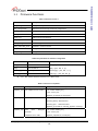
Firmware Structure
Table 6 Project Hierarchy
Directory
Files
Decryption
USER
main.c
W5200E01-M3 main function
W5200.c, W5200.h
I/O functions for W5200
socket.c, socket.h
Socket APIs for W5200
loopback.c, loopback.h
TCP, UDP Loopback Apps implementation
SPI2.c
STM32F103x SPI Interface initialization
util.c, util.h
Utilities
dhcp.c, dhcp.h
DHCP App implementation
md5.c, md5.h
md5 hash algorithm implementation for PPPoE
stm32f10x_it.c
Main Interrupt Service Routines
system_stm32f10x.c
Cortex-M3 Device Peripheral Access Layer System
CMSIS
core_cm3.c
Cortex™ Microcontroller Software Interface Standard
EWARMv5.4
startup_stm32f10x_md.s
STM32F10x Medium Density Devices vector table
EWARMv5.4/
misc.c
miscellaneous firmware functions
StdPeriph_Driver
stm32f10x_bkp.c
BKP firmware functions
stm32f10x_flash.c
FLASH firmware functions
stm32f10x_gpio.c
GPIO firmware functions
stm32f10x_rcc.c
RCC firmware functions
stm32f10x_spi.c
SPI firmware functions
stm32f10x_tim.c
TIM firmware functions
stm32f10xusart.c
USART firmware functions
© Copyright 2011 WIZnet Co., Inc. All rights reserved.
17
W5200E01-M3 User’s Guide
9.2
Table 7 Functions in main.c
Function
Description
RCC_Configuration
Configure the system clocks
NVIC_Configuration
Nested Vectored Interrupt Controller configuration
GPIO_Configuration
Configure the General Purpose I/O Pin
Reset_W5200
W5200 Reset Function
UART1_Init
UART Interface Initialization
WIZ_SPI_Init
W5200 SPI Interface Initialization
Timer_Configuration
Timer Configuration
LED3_onoff/LED4_onoff
USER LED n Control Function
Set_network
Configure Network In formations for W5200
WIZ_Config
Configure Network In formations
Table 8 Key Variables for Network Configuration
Variable
Description
Example Code (Location: main.c)
MAC[6]
MAC address
MAC[6] = {0x00, 0x08, 0xDC, 0x01, 0x02, 0x03};
IP[4]
Local IP address
IP[4] = {192, 168, 11, 4};
GateWay[4]
Gateway address
GateWay[4] = {192, 168, 11, 1};
SubNet[4]
Sub
SubNet[4] = {255, 255, 255, 0};
Note : MAC address should be defined even if DHCP mode.
Table 9 Functions in Loopback.c
Function
Description
Example Code (Location: loopback.c)
loopback_tcps
TCP Loopback server mode
- ch : socket number [0-7]
- port : source port
loopback_tcps(uint8 ch, uint16 port)
loopback_tcpc
TCP Loopback client mode
- ch : socket number [0-7]
-ChConfig.destip : Destination IP
-ChConfig.port
: Destination Port
loopback_tcpc(uint8 ch, CHConfig_TypeDef* ChConfig)
loopback_udp
UDP
(User
Datagram
- ch : socket number [0-7]
Protocol)
- port : source port
Loopback server mode
loopback_udp(uint8 ch, uint16 port)
© Copyright 2011 WIZnet Co., Inc. All rights reserved.
18
W5200E01-M3 User’s Guide
Firmware Functions
9.3
Firmware Build and Upload
9.4.1
Build – IAR Embedded Workbench IDE
To build and link you project choose “Make” form the “Project” menu, or press F7.
Figure 8 Compile on IAR Embedded Workbench IDE
© Copyright 2011 WIZnet Co., Inc. All rights reserved.
19
W5200E01-M3 User’s Guide
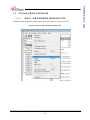
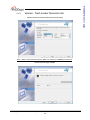
9.4
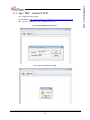
Upload – Flash Loader Demonstrator
Upload 1 Select the Communication port and set setting
Note - PROG S/W should be selected ‘PROG’ to connect to W5200E01-M3 with PC.
Upload 2 Check target readable
© Copyright 2011 WIZnet Co., Inc. All rights reserved.
20
W5200E01-M3 User’s Guide
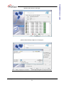
9.4.2
Upload 4 Choose Binary image file in work project
Note - Binary image file’s location:
…\Work\App\Debug\Exe in project directory
© Copyright 2011 WIZnet Co., Inc. All rights reserved.
21
W5200E01-M3 User’s Guide
Upload 3 Select device in the target
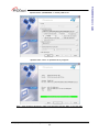
Upload 6 Select “Next” to upload the binary image file
Note - After finishing ‘Download’, PROG S/W should be selected ‘RUN’ to run User APP.
© Copyright 2011 WIZnet Co., Inc. All rights reserved.
22
W5200E01-M3 User’s Guide
Upload 5 Select ”@0x08000000” in memory address list
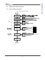
Application Demonstration
10.1 Flow of Demonstration
Figure 9 Flow Chat of Demonstration
© Copyright 2011 WIZnet Co., Inc. All rights reserved.
23
W5200E01-M3 User’s Guide
10
A ping test determines whether your test PC can communicate with the W5200E01-M3 over
the network.
10.2.1
Network configuration for TEST PC
1.
Access the "Start" menu and click "Control Panel."
2.
Click "Network Connections"
3.
Right-click the name of your network in the list of available networks. Select "Properties."
4.
Navigate to the "General" tab. Scroll down through the list of connection types and locate the
"Internet Protocol (TCP/IP)" entry.
5.
Right-click the entry and select "Properties."
6.
Co figurate IP address, subnet mask and Default gateway as follow figure.
Figure 10 Internet Protocol Properties
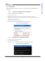
10.2.2
Ping Test at Command Prompt
1.
Access the “ Start” in the menu, click “Run”.
2.
Enter “cmd" in the "Open:" field,
3.
Type “ping 192.168.11.4” (W5200E01-M3 IP address) in Command Prompt window
Figure 11 Ping Test at Command Prompt
© Copyright 2011 WIZnet Co., Inc. All rights reserved.
24
W5200E01-M3 User’s Guide
10.2 Ping TEST
-
AX1 : Loopback test program
-
Download URL : http://www.wiznet.co.kr/UpLoad_Files/ReferenceFiles/AX1.zip
AX1.zip : AXInstallV3.1.exe, AX1 Manual V3.1.pdf
Run 1 Input W5200E01-M3 IP and Port
Run 2 Check “Connected” message
© Copyright 2011 WIZnet Co., Inc. All rights reserved.
25
W5200E01-M3 User’s Guide
10.3 App. TEST – Loopback TEST
Run 4 Check the status message in dialog window
© Copyright 2011 WIZnet Co., Inc. All rights reserved.
26
W5200E01-M3 User’s Guide
Run 3 Set Data format; size and base Value
W5200E01-M3 User’s Guide
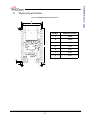
11
Physical Specification
Figure 12 W5200E01-M3 Board Dimension
a
b
g
c
f
e
d
d
© Copyright 2011 WIZnet Co., Inc. All rights reserved.
27
Symbols
Dimensions (mm)
a
28.00
b
25.40
c
52.00
d
1.30
e
1.87
f
2.54
g
1.87
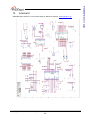
Schematic
W5200E01-M3 Schematic can be downloading at WIZnet Homepage, www.wiznet.co.kr.
© Copyright 2011 WIZnet Co., Inc. All rights reserved.
28
W5200E01-M3 User’s Guide
12
Revision
Ver. 1.0
Data
APR 14, 2011
Description
Release
Copyright Notice
Copyright 2011 WIZnet, Inc. All Rights Reserved.
Technical Support: [email protected]
Sales & Distribution: [email protected]
For more information, visit our website at http://www.wiznet.co.kr
© Copyright 2011 WIZnet Co., Inc. All rights reserved.
29
W5200E01-M3 User’s Guide
Document History Information
Mouser Electronics
Authorized Distributor
Click to View Pricing, Inventory, Delivery & Lifecycle Information:
WIZnet:
W5200E01-M3