1
Version 1.2.1
Because of the variety of uses for the products described in this publication,
those responsible for the application and use of this control equipment must
satisfy themselves that all necessary steps have been taken to assure that each
application and use meets all performance and safety requirements, including any
applicable laws, regulations, codes and standards.
The illustrations, charts, sample programs and layout examples shown in this
guide are intended solely for purposes of example. Since there are many variables
and requirements associated with any particular installation, RS Automation does
not assume responsibility or liability (to include intellectual property liability) for
actual use based upon the examples shown in this publication.
Reproduction of the contents of this manual, in whole or in part, without written
permission of RS Automation Co., Ltd. is prohibited.
Throughout this manual, when necessary, we use notes to make you aware of
safety considerations.
Identifies information about practices or circumstances that
can cause an explosion in a hazardous environment, which
may lead to personal injury or death, property damage, or
economic loss.
Identifies information that is critical for successful application
and understanding of the product.
Identifies information about practices or circumstances that
can lead to personal injury or death, property damage, or
economic loss. Attentions help you identify a hazard, avoid a
hazard, and recognize the consequence.
Labels may be located on or inside the equipment, for
example, a drive or motor, to alert people that dangerous
voltage may be present.
Labels may be located on or inside the equipment, for
example, a drive or motor, to alert people that surfaces may be
at dangerous temperatures.
Trademarks not belonging to RS Automation Co., Ltd. are property of their respective companies.
Important User Information ........................................................................................... 2
Preface .....................................................................................................................6
Introduction ................................................................................................................... 6
Who Should Use This Manual ........................................................................................ 6
Where to Find Help
6
Conventions Used in This Manual .................................................................................. 6
Related Documentation ................................................................................................. 6
Using Online Help ........................................................................................................... 7
RS Automation Support ................................................................................................. 7
Local Product Support
Technical Product Assistance
7
7
Before You Begin ....................................................................................................8
Introduction ................................................................................................................... 8
Chapter Overview .......................................................................................................... 8
Understanding the RSWare Interface ............................................................................. 8
Workspace window
Client Area
Main Menubar
Toolbars
Status Bar
9
10
10
11
11
Starting RSWare..........................................................................................................12
Opening an RSWare File
Scanning the Network
Serial Port Settings
12
12
13
Upgrading Firmware ....................................................................................................13
RSWare Manual
Common Commands for RSWare Drive Configuration ...................................... 14
Chapter Overview ........................................................................................................14
Opening RSWare ..........................................................................................................14
Creating, Opening and Saving RSWare Files.................................................................15
Creating a New RSWare File
Opening an Existing RSWare File
Saving an RSWare File
15
16
17
Creating a New Drive ..................................................................................................17
Importing and Exporting a Drive ...................................................................................18
Exporting a Drive
Importing a Drive
18
19
Working in the Workspace Window ..............................................................................19
Cut
Copy
Paste
Delete
Drag and Drop
19
20
20
21
22
Examining the CSD5 Drive Interface .................................................................. 24
Chapter Overview ........................................................................................................24
Configuring an CSD5 ...................................................................................................25
Configuring Properties for the CSD5 Drive
25
CSD5 Drive Branch ......................................................................................................27
Velocity Control Panel Window
43
Understanding the Analog Window ..............................................................................45
Understanding the Preset Window ...............................................................................47
Understanding the Follower Window............................................................................50
CSD5 User Manual
Understanding the Indexing Window ............................................................................54
Indexing Control Panel
Indexing Teaching Panel
59
60
Understanding the Homing Window .............................................................................61
Understanding the Motor Window ...............................................................................67
Understanding the Tuning Window ..............................................................................70
Understanding the Encoders Window ...........................................................................84
Understanding the Digital Inputs Window ....................................................................86
Understanding the Digital Outputs Window............................................................... 100
Understanding the Analog Outputs Window .............................................................. 108
Understanding the Monitor ....................................................................................... 110
Understanding the Oscilloscope Window................................................................... 112
Channel Setup Window
116
Understanding the Faults Window ............................................................................ 117
Understanding the Service Information Window ....................................................... 123
RSWare Manual
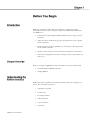
Read this preface to familiarize you with the rest of the manual. This preface
covers the following topics:
• Introduction
• Who Should Use this Manual
• Conventions Used in this Manual
• Related Documentation
• Using Online Help
• RS Automation Support
Use this manual when RSWare Version1.2.1 is used to configure and operate
CSD5 (Firmware Ver1.21) and KNX3 (Firmware Ver1.10) drives.
You can find help for RSWare in both this User Manual, and Online Help.
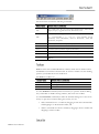
The following conventions are used throughout this manual.
• Bulleted lists provide information, not procedural steps
• Numbered lists provide sequential steps.
• Words you type or select, and keys that you press, appear in bold
These publications provide additional information. To obtain a copy, contact
your local RS Automation office or distributor, or access the documents on-line
at www.rsautomation.co.kr or http://www.rsautomation.biz/.
RSWare User Manual
Information on the installation
of your CSD5 servo drive
Information on the motors
used together with CSD5 servo
drive
CSD5 User Manual
CSD5 Servo Drive Installation
Instructions
CSD5-IN001
Servo Motor User Manual
SMOTORUM002
CSD5 User Manual
CSD5-UM001A
The following types of online help are available:
RSWare Help
Context
Help
Sensitive
Select Contents and Index
from the Help menu.
Navigate the help files using
the Table of Contents, the
Index and the Search tabs
Either:
•Click on a Help button in
the active window, or
•Select an on-screen object
press F1
Descriptions of all on-screen
object.
Object property configuration
settings.
How to information.
For help about the selected
object.
Contact your local RS Automation representative for:
• Sales and order support
• Product technical training
• Warranty support
• Support service agreements
If you need to contact RS Automation for technical assistance, please review
the information in this manual or in the Online Help file first. Then call your
local RS Automation representative. For the quickest possible response, we
recommend that you have the catalog numbers of your products available when
you call.
RSWare User Manual
RSWare is a Windows 2000, XP, Vista, Windows 7 application by RS
Automation that provides a complete setup for the CSD5 and KNX3 drives.
Use RSWare to:
• Communicate with multiple CSD5 and KNX3 drives, using your PC's
serial port.
• Adjust the drives' feedback loop gains and parameters for the specific
motors and loads.
• Define the drives' motion capabilities by selecting the operating modes
for the CSD5 or KNX3.
• Monitor a wide variety of status and motion parameters on the drives.
• Customize the application interface to display only the information you
wish to see.
Before you begin using RSWare, read this chapter to become familiar with:
• Understanding the RSWare Interface
• Starting RSWare
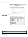
RSWare provides a graphical user interface within which you configure your
drives. The workspace consists of:
• a Workspace window
• a Client Area
• an Output window
• a Main menubar
• a set of Toolbars
• a Status bar
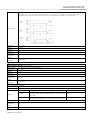
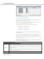
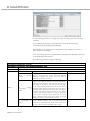
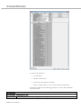
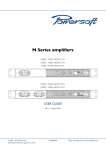
RSWare User Manual
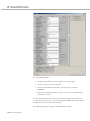
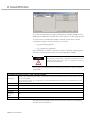
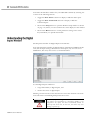
Use the View menu commands to enable and disable these RSWare
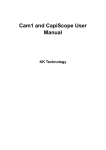
The RSWare user interface for CSD5 and KNX3 drives, with several features
enabled, looks like this:
Main menubar
Toolbars
Workspace Window
Properties Windows:
CSD5
KN3
KN3
KN3
KN3
KN3
KN3
Client area
Status bar
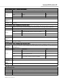
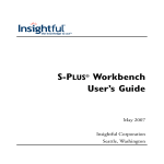
The Workspace window is located, by default, beneath the menubar and
toolbars, and above the Status Bar. Use the F7 key to return focus to the
Workspace window.
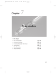
The Workspace window has two main branches:
RSWare User Manual
On-Line
branch
Drives
RSWare
branch
File
All connected on-line drives and their child objects.
All configured off-line CSD5 and KNX3 drives, their child
objects.
Use the Workspace window to navigate to all of the connected on-line and offline objects and perform the following tasks:
• Create new Drive.
• Cut, Copy, Paste and Delete selected Workspace window objects.
• Open the Properties dialog box for selected Workspace window objects.
You can resize and move the Workspace window in several ways:
• With the Workspace window in its default state (i.e., attached to the
RSWare interface) you can double-click on the Workspace window's title
bar to detach it from the RSWare interface.
• Once detached, the Workspace window possesses all the properties of
any window. It can be resized or moved entirely outside the RSWare
interface.
• To return the Workspace window to its default position, just double
click on its title bar.
To hide the Workspace window, de-select the Workspace selection in the View
menu.
The Client Area is the large gray area located, by default, beneath the menubar
and toolbars and to the right of the Workspace window.
Use the Client Area to display:
• Property windows for objects selected in the Workspace window, where
you can configure the selected object's properties.
Selecting Workbook Mode from the View menu displays a tab for each object
in the Client Area. The tab contains the abbreviated name of the related object.
Select a tab to bring the related object to the top of the Client Area.
Unlike windows, the Client Area cannot be directly resized. The size of the
Client Area depends upon the size and location of the surrounding Workspace
and Output windows, the Main menubar, the Status Bar and the several
toolbars.
However, you can use the Cascade, Tile Wide, Tile Tall and Arrange Icons
Window menu commands to arrange the display of windows in the client area.
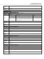
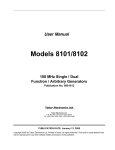
The Main menubar is located at the top of the RSWare interface. Use it to
customize the RSWare main window, and to perform essential functions and
procedures with respect to objects selected in the Main Window.
The main menubar looks like this:
RSWare User Manual
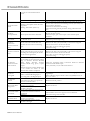
The menu items contain the following commands:
File
New, Open, Save, Save As, Close, Print, Print Preview, Print Setup,
Import, Export, Upgrade Firmware, Recent File, Exit
Undo, Redo, Cut, Copy, Paste, Delete, Find, Replace, Select All, Go
Edit
To… Corresponding { } ( ), Go To …Line Number, Toggle
Bookmark, Next Bookmark, Previous Bookmark, Clear All
Bookmarks, Properties
View
Toolbars, Status Bar, Workspace, Output, Workbook Mode
Insert
CSD5, KNX3
Tools
Customize, Rescan, Rescan Options, Serial Port,
Commands
Enabled
Window
Close All, Cascade, Tile Wide, Tile Tall, Arrange Icons
Contents and Index, Tip Of The Day, Release Notes, About
RSWare
Help
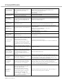
RSWare offers four standard Windows toolbars, which can be detached from
the RSWare user interface and relocated. To return a toolbar to its last docking
position, just double-click on its header bar.
The RSWare toolbars are:
File
Edit
Enable
New, Open, Save, About, Locate
Cut, Copy, Paste, Erase
Enable, Disable All
Use the Toolbars command (in the View menu) to open the Toolbars dialog
box, and enable or disable existing toolbars, and create new toolbars.
Use the Customize command (in either the Toolbars dialog box or the Tools
menu) to open the Customize dialog box, where you can:
• add a command icon to a toolbar by dragging it from the Command tab
and dropping it on the desired toolbar, and
• delete a command icon from a toolbar by dragging it from a toolbar and
dropping it off the toolbar.
RSWare User Manual
To display the Status bar, use the View menu Status Bar command. The status
bar contains:
• Tooltip help: a description of the menu or button command immediately
beneath the pointer.
• Indicators for caps lock (CAP), num lock (NUM) and scroll lock (SCRL).
• The Row and Column reference for the cursor, if a source file or header
file has focus in the Text Editor.
When the status bar is visible, a check mark appears to the left of the Status Bar
command in the View menu.
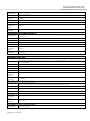
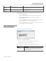
When you start RSWare for the first time, RSWare prompts you to Open Last
File, xxx.udb, Open existing file, or Create new file. After you select the file
to open or create, RSWare scans the network for online drives.
You may need to configure your PC's serial port settings (Refer to Serial Port
Settings on page 13) and rescan the network (Refer to Scanning the Network
on page 12) to insure that RSWare successfully locates all online network drives.
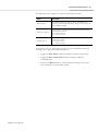
RSWare stores the name and location of any open RSWare file in its memory,
when you last closed RSWare. Each time RSWare opens, it displays a dialog
box that lets you do one of the following:
Open
Last
File,
xxx.udb and then OK
Open existing file and
then OK
Create new file and
then OK
Cancel
Opens the most recently used RSWare file.
Open another, existing RSWare file of your choice.
Open a new RSWare file.
Open RSWare without an active file in the Workspace
window.
Note: A new file is stored in temporary storage until saved.
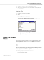
Every time RSWare opens, it conducts a search of the network for all
connected drives. A Scan For On-Line Drives dialog box appears. This dialog
box displays RSWare's progress in checking for on-line drives on nodes 0 to 10,
and the specific task RSWare is currently undertaking (e.g., Scanning Node…
or Attaching to Node…).
RSWare User Manual
To stop the process of scanning for - and attaching to - on-line drives, click on
the Stop Scanning button.
RSWare displays every drive it detects in the On-Line Drives branch of the
Workspace window. Because RSWare does not automatically update the
Workspace window, select Rescan from the Tools menu to display the list of
drives that are currently on-line.
After you open RSWare for the first time, you may wish to change the
configuration of your PC's serial port and baud rate settings from the defaults
of COM1, 57600 Baudrate, 8 Data bits and No Parity. To do this:
1.
Select Serial Port… from the Tools menu.
2.
In the PC Communications Setup dialog box, type the appropriate serial
port settings.
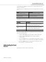
You can use the RSWare interface to upgrade the firmware for a selected online drive. Use the Upgrade Firmware…command (in the File menu) to open
the Firmware Upgrade dialog box, where you can perform a flash upgrade to
the firmware of a drive appearing in the On-Line Drives branch of the
Workspace window. Before issuing the Upgrade Firmware…command, be sure
to first obtain a copy of the new firmware and any related instructions.
To upgrade firmware in the Firmware Upgrade dialog box:
1.
Select the drive for firmware upgrade from the list of On-Line Drives. If a
drive name has been left blank, it is identified as < Drive>.
2.
Enter the pathname of the new firmware file. Either type in the pathname,
or use the browse button (marked with an ellipsis "…") to navigate to the
new firmware file. (The new firmware file must have an extension of .hex.)
3.
Select the Begin Load button. RSWare informs you of firmware upgrade
progress using both a progress bar and status messages.
You can cancel the firmware upgrade during the upgrade
process by selecting the Cancel button. However, If you
cancel the firmware upgrade while it is in progress, the selected
drive ceases to be functional. Thereafter, the selected drive can
be used only to complete a subsequent firmware upgrade.
RSWare User Manual
Use RSWare to configure both an on-line and an off-line drive. You can
configure an on-line drive, then copy or move it to an off-line RSWare file, or
configure an off-line drive (in an RSWare file), then copy and paste it onto an
existing on-line drive, thereby overwriting the on-line drive's settings. You can
also use RSWare's drag-and-drop functionality to accomplish the copy and
paste process in a single step.
This chapter covers:
• Opening RSWare
• Creating, Opening and Saving RSWare Files
• Creating a New Drive
• Importing and Exporting a Drive
• Working in the Workspace Window
Before you create a new off-line drive, you must first create an RSWare file to
contain the new drive. When RSWare opens for the first time, a dialog box like
the following one appears:
If you:
• Select Open Last File:<filename> and click OK, RSWare opens the
most recently used RSWare file.
• Select Open existing file… and click OK, the Open dialog box appears,
where you can navigate to and open a previously saved RSWare file.
RSWare User Manual
• Select Create new file and click OK, a new, empty file is created.
Note: A new file is stored in temporary storage, and the Workspace icon
displays Unsaved until the file is saved with a filename.
• Click the Cancel button, RSWare does not open an RSWare file.
RSWare displays the selected RSWare file, if any, in an Off-Line branch of the
Workspace window.
An RSWare File is a container that can hold any number or combination of offline CSD5 and KNX3 drives, projects and their children. An RSWare File is
distinguished by its extension of .udb
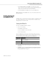
To create a new RSWare DataBase (.udb) file:
1.
Do one of the following:
• Select New in the File menu
• Click on the New icon in the File toolbar
• Press the Ctrl + N keys
Note: If an RSWare file is already open, a Save Changes dialog opens and
requires a response before the request to open a new file executes. Choosing
one of the following from the dialog opens the new RSWare file:
RSWare User Manual
Yes
Saves the open file under the filename and location
previously designated.
No
Discards the changes to the open file.
Cancel
Aborts the new RSWare file, leaving the previous file open.
2.
A new RSWare File, titled Unsaved, appears in the Workspace under OnLine Drives.
3.
The RSWare file can be populated with drives as described in "Creating a
New Drive" on page 17, and saved under a name using the directions in
"Saving an RSWare File" on page 17.
To open an existing RSWare File:
1.
Do one of the following:
• Select Open in the menu.
• Click on the Open icon in the File toolbar
• Press the Ctrl +O Keys
Note: If an RSWare file is already open, a Save Changes dialog opens and
requires a response before the request to open a new file executes. Choosing
one of the following from the dialog opens the new RSWare file:
Yes
Saves the open file under the filename and location
previously designated.
No
Discards the changes to the open file.
Cancel
Aborts the new RSWare file, leaving the previous file open.
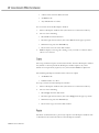
The Open dialog box opens:
RSWare User Manual
2.
Navigate to and select the name of the RSWare File to open.
3.
Click Open. The selected RSWare File appears in the Workspace window.
If the Workspace window had displayed a previously opened RSWare File,
the selected RSWare File is displayed in its place.
To save all changes made to a drive or a project:
1.
Do one of the following:
• Select Save in the File menu.
• Click on the Save icon in the File toolbar
• Press the Ctrl +S keys
To save an RSWare File to a new filename:
1.
Select Save As in the File menu. The Save As dialog box opens:
2.
Type or select a file name.
3.
Navigate to the location where the new RSWare File should be stored.
4.
Click Save.
Note: Save As saves the entire RSWare database (.udb) file to a new name.
With an RSWare File open in the Workspace window, you can add a new offline CSD5 or KNX3 drive.
To add a new CSD5 drive, do one of the following:
• Select CSD5 from the Insert Menu.
• With the RSWare File selected, click the right mouse button, then select
Insert CSD5 from the pop-up menu.
A new CSD5 drive appears as the bottom drive in the Workspace window. The
name of the new drive is Drive or (if Drive already exists) Drive n, where n is
RSWare User Manual
the lowest positive integer that creates a unique drive name for the specific
drive model.( i.e., Two CSD5 drives may be named Drive and Drive1, and two
KNX3 drives may also be named Drive and Drive 1.)
To add a new KNX3 drive, do one of the following:
• Select KNX3 from the Insert Menu.
• With the RSWare File selected, click the right mouse button, then select
Insert KNX3 from the pop-up menu.
A new KNX3 drive appears as the bottom drive in the Workspace window.
The name of the new drive is Drive or (if Drive already exists) Drive n, where n
is the lowest positive integer that creates a unique drive name.
You can import an existing, previously configured drive to an RSWare File
using the File menu's Import command.
Only drives that have been previously exported, using the File menu's Export
command, can be imported. Exporting a drive saves it as an User data
eXchange File with an .uxf extension.
To Export a drive:
1.
Select a drive branch.
2.
Do one of the following:
• Select Export from the File menu, or
• Place the cursor over the select drive branch, click the right mounse
button and select Export from the pop-up menu.
The Export to dialog box opens:
3.
RSWare User Manual
In the Export To dialog box, type or select a name for the drive.
4.
Navigate to a location to which the file should be exported.
5.
Click Save. The exported file is saved as an User data eXchange File (with
an .uxf extension).
1.
To Import a previously exported drive:
2.
Either:
• Select Import from the File menu or
• Place the cursor over the selected RSWare File, click the right mouse
button and select Import from the pop-up menu.
The Import From dialog box open:
3.
In the Import From: dialog box, navigate to and select the User data
eXchange File (.uxf) that contains the desired drive settings.
4.
Click Open. RSWare displays the imported drive in the off-line RSWare
file.
You can use the Edit menu commands to Cut, Copy, Paste and Delete/ Erase
items in the Workspace window. You can also use RSWare's Drag and Drop
function in place of Cut and Paste.
The Cut command removes certain selected items from the Workspace window.
Any item cut from the Workspace window replaces any other item previously
cut (or copied) and stored in RSWare's clipboard.
The following Workspace window items cannot be cut:
• The On-Line Drives branch
RSWare User Manual
• A drive in the On-Line Drives branch
• An RSWare file
• Any child branch of a drive
To cut an item from the Workspace window:
1.
Select a Workspace window item (other than one of those listed above).
2.
Do one of the following:
• Select Cut from the Edit menu
• Click the right mouse button, then select Cut from the pop=up menu
• Simultaneously press the Ctrl +X keys
• Click on the Cut icon in the Edit toolbar.
3.
RSWare displays a message box asking you if you wish to continue. Select
OK to cut or Cancel.
The Copy command copies certain selected items from the Workspace window.
Any branch or item copied in the Workspace window replaces any other
branch or item previously copied (or cut) and stored in RSWare's clipboard.
The following Workspace window items cannot be copied:
• An RSWare file
• Child branches of a drive.
To Copy an item from the Workspace window:
1.
Select a Workspace window item (other than one of those listed above).
2.
Do one of the following:
• Select Copy from the Edit menu
• Click the right mouse button, then select Copy from the pop=up menu
• Simultaneously press the Ctrl +C keys
• Click on the Copy icon in the Edit toolbar.
The Paste command inserts a previously copied or cut Workspace window item
or branch into the selected location of the Workspace window.
RSWare User Manual
When pasting into the Workspace window, three results can occur:
• If the selected Workspace window item is of the same type as the item to
be pasted, the pasted item REPLACES the selected item.
• If the selected Workspace window item is a parent branch that must
always have one child of the same type as the item to be pasted, the
pasted item REPLACES the selected branch's child of the same type.
• If the selected Workspace window branch can have multiple child
branches of the same type as the item to be pasted, the pasted item:
- REPLACES a child branch with the same name as the pasted item, or
- is ADDED as an additional child branch, if no other child branch
shares the pasted item's name.
Any Workspace window item can be selected to receive a pasted item except
the following:
• Child branches of a CSD5 drive.
• Child branches of a KNX3 drive.
To Paste an item in the Workspace window:
1.
Select a Workspace window branch (other than On-Line Drives, a child
project in Archives, or a drive's children.)
2.
Do one of the following:
• Select Paste from the Edit menu
• Click the right mouse button, then select Paste from the pop-up menu
• Simultaneously press the Ctrl + V keys
• Click on the Paste icon in the Edit toolbar.
If you are pasting an item into the Workspace window that replaces
another item of the same name, RSWare displays a message box asking
you if you wish to continue.
3.
Select OK to paste or Cancel.
The Delete command removes selected branches or items from the Workspace
window. The deleted item is permanently destroyed. The Delete command
cannot be reversed by an Undo command.
The following Workspace window items cannot be deleted:
• The On-Line Drives branch
• A drive in the On-Line Drives branch
• An RSWare file
RSWare User Manual
• An immediate child item branching directly from a drive
To Delete an item in the Workspace window:
1.
Select a Workspace window branch (other than one those listed above).
2.
Do one of the following:
• Select Delete from the Edit menu
• Click the right mouse button, then select Delete from the pop-up menu
• Click on the Erase icon in the Edit toolbar.
RSWare displays a message box asking you if you wish to continue.
3.
Select OK to paste or Cancel.
You can use the drag-and-drop method to copy and move a Workspace
window branch or item to other locations within the Workspace window. The
drag-and-drop method combines the Cut, Copy and Paste commands, as
follows:
• the drag-and-drop method copies a Workspace window branch or item
that can be both copied using the Copy command, and pasted using the
Paste command.
• the drag-and-drop method moves a Workspace window branch or item
that can be both cut using the Cut command, and pasted using the Paste
command.
To use the drag-and-drop method to copy a Workspace window branch or item:
1.
Place the cursor arrow on a Workspace window branch or item that can be
copied and hold down the left mouse button
2.
Drag the selected Workspace window branch or item to the desired
destination. One of two things happens:
• If the item can be copied, the pointer continues to appear as an arrow
and a + (plus) sign appears to the right of the arrow (for as long as you
continue drag the item over a place in the Workspace window where it
may be dropped).
• If the item cannot be copied, or if you are dragging the item over a part
of the Workspace window where it may not be dropped, the arrow is
replaced by a circle with a line through it.
3.
Release the mouse button when you arrive at the Workplace window
location where you want to copy the Workspace window branch or item.
The result is the same as if you had Copied then Pasted it to this location.
To use the drag-and-drop method to move a Workspace window branch or
item:
1.
RSWare User Manual
Place the cursor arrow on a Workspace window branch or item that can be
cut and hold down the left mouse button
2.
Drag the selected Workspace window branch or item to the desired
destination. One of two things happens:
• If the item can be cut, the pointer continues to appear as an arrow (for as
long as you continue drag the item over a place in the Workspace
window where it may be dropped).
• If the item cannot be cut, or if you are dragging the item over a part of
the Workspace window where it may not be dropped, the arrow is
replaced by a circle with a line through it.
3.
RSWare User Manual
When you arrive at the Workplace window location where you want to
move the item, release both the mouse button and the Ctrl key. The result
is the same as if you had Cut then Pasted it to this location.
A CSD5 drive may be set up in one of several operational modes.
• Analog Velocity Controller
• Analog Current Controller
• Preset Velocity Controller
• Position Follower using an Auxiliary Encoder
• Position Follower using Step and Direction controls
• Position Follower Step Up and Step Down controls
• Indexing Controller
The CSD5 drive interface also provides Homing, Oscilloscope, drive Tuning
and Monitor capabilities, and Motor and Encoder Diagnostic routines.
This chapter covers:
• Configuring an CSD5 Drive
• Understanding the CSD5 Drive Branch
• Understanding the Analog Window
• Understanding the Preset Window
• Understanding the Follower Window
• Understanding the Indexing Window
• Understanding the Homing Window
• Understanding the Motor Window
• Understanding the Tuning Window
• Understanding the Encoders Window
• Understanding the Digital Inputs Window
• Understanding the Digital Outputs Window
• Understanding the Analog Outputs Window
• Understanding the Monitor
RSWare User Manual
• Understanding the Oscilloscope Window
• Understanding CSD5 Statuses
• Understanding the Faults Window
• Understanding the Service Information Window
Each CSD5 drive in the Workspace window has the following child branches
or windows:
• Operation Modes
-Analog
-Preset
-Follower
-Indexing
-Homing
• Motor
• Tuning
• Encoders
• Digital Inputs
• Digital Outputs
• Analog Outputs
• Monitor
• Oscilloscope
• Faults
• Service Information
Except for the Monitor windows, all of a drive's child branches can and must
be configured in a Properties window.
To configure the properties for an CSD5 drive or one of its child branches:
1.
In the Workspace window, select the drive branch to configure.
2.
Do one of the following:
• Select Properties… from the Edit menu.
RSWare User Manual
• Click the right mouse button and select Properties… from the pop-ip
menu.
• Double click on the selected drive branch.
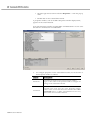
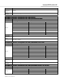
A properties window, such as the Drive Properties window display below,
appears for the selected branch.
Note: The Properties window of CSD5 Drive and KNX3 Drive are not same.
The below is an illustration of CSD5 Drive.
3.
RSWare User Manual
To configure properties for the selected drive branch, use the features of
the Properties window as follows:
Parameters
Located in the upper left part of the Properties window.
Type or select values in the parameter fields to configure the
settings of the selected drive branch.
Commands
Located in the upper right part of the Properties window.
Click a button to issue the associated command. Select show
Commands, below, to display command buttons. Not every
drive branch has associated commands.
Statuses
Located beneath the Parameters and Commands sections.
By default, these fields display the on-line status of the
selected drive branch. Click on Setup to open a window
where you can customize the statuses to be displayed. Status
fields are read-only. Select Show Status to display the status
section.
Note: Status values for off-line drives may not be
meaningful.
Show Status
Select this to display statuses for the selected drive branch.
Show
Command
Select this to display commands for the selected drive branch.
Commands can be executed only for on-line drives. This
selection is grayed-out if no commands are associated with
the selected drive branch.
Setup
Opens the Monitor Setup window, where you can customize
the Statuses that are displayed.
Refer to Understanding the Monitor on page 111 for more
information about using the Monitor window.
Revert
Click this button to return parameter settings to the values
they had when you first opened this window.
Close
Closes the window.
Help
Click this button to get online help for this window.
The remainder of this chapter describes the process of entering and editing
drive configuration settings, the statuses that are displayed by default for each
drive branch when the drive is on-line, and the commands available to a user
for each drive branch when the drive is on-line.
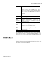
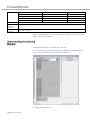
The Properties window for the CSD5 Drive branch looks like this:
Note: The Properties window of CSD5 Drive and KNX3 Drive are not same.
The below is an illustration of CSD5 Drive.
RSWare User Manual
Use this CSD5 window to:
• configure the parameters for an off-line or an on-line drive
• monitor the status of an on-line drive
• execute commands that clear faults, reset the drive or reset the
EEPROM
• open the Control Panel windows, where you can issue commands that
control drive motion
You can edit parameters for both an on-line and an off-line drive. However,
you can monitor statuses (i.e., executed through the RSWare interface) only for
a CSD5 drive in the On-Line Drives branch.
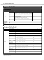
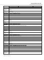
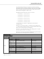
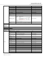
The following parameters apply to the CSD5 Drive window:
RSWare User Manual
Parameter
The name of the drive.
Note: The drive name is displayed in the title bar of the windows relating to this drive.
-
Range:
up to 32 characters long.
Default:
Applicable
Operating
Mode
When
Enabled
Drive
Description
Parameter
Select main power input source
[Ft – 0.02]- Digit 3
Select
Description
Value
Enable.
50~400W drive: Enable single-phase open check 0.8~1.5kW
0x0
drive :Enable 3-phase open check
Disable
Do not check the input power
0x1
Single
phase
Single-phase input
0x2
input
Enable
Description
Range:
Default:
Applicable
Operating
Mode
When
Enabled
Description
Parameter
Range:
Default:
Applicable
Operating
Mode
When
Enabled
Description
Parameter
Range:
Default:
Applicable
Operating
Mode
All
Immediately
All
Servo-Off -> Setting
Set Motor type
Set three items of the motor: motor type, motor rated output, and encoder type.
[Ft – 0.01]
CSMT-04BR for CSD5 Drive; CSM-A3BB for KNX3 Drive
All
Servo-Off -> Setting -> After power cycle
Direction of Motor Rotation
[Ft – 0.02]- Digit 2
Select
Description
The command signal is not inverted so that a positive
Normal
command value results in CW Rotation, (as viewed from
shaft end).
The command signal is inverted so that a positive command
Inverted
value results in CCW Rotation, (as viewed from shaft end).
Normal
All
RSWare User Manual
Value
0x0
0x1
When
Enabled
Description
Parameter
Range:
Default:
Applicable
Operating
Mode
When
Enabled
Description
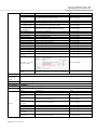
Parameter
Servo-Off -> Setting
Select a unit of measure for position, velocity, and acceleration displays
Select
Description
units for rotary motors are: counts (position), RPM
(velocity), revs/ sec2 (acceleration);units for linear motors are:
Metric
meters (position), meters/ sec2 (velocity), and meters/ sec2
(acceleration).
units for rotary motors are: counts (position), RPM(velocity),
revs/sec2(acceleration);
English
units for linear motors are: inches (position),
inches/sec2(velocity), and inches/sec2(acceleration).,
displays measurements in terms defined by the user in the
User
Units section.
Metric
Default:
-
-
All
Servo-Off -> Setting
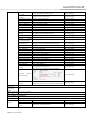
Select the combination of operation modes to be used when the Operation Mode Override digital input is
active or inactive.
[Ft – 0.00]
Select
Description
Value
Follower/None
Range:
Value
Analog
Velocity
Input/ None
Analog
Current
Input/ None
Analog
Velocity
Input/ Follower
Analog
Velocity
Current/ Follower
Analog
Current
Input/Analog
Velocity Input
Preset Velocity /
None
Preset Velocity /
Follower
Preset
Velocity/Analog
Velocity Input
Preset
Velocity/Analog
Current Input
Indexing
Input/
None
Follower/None
RSWare User Manual
Position control mode
F(1)
Speed control mode
S(2)
Torque control mode
C(3)
Speed + position mode
SF(4)
Torque + position control mode
CF(5)
Torque + speed
CS(6)
control mode
Multi-step speed control mode
P(7)
Multi-step speed + position control mode
PF(8)
Multi-step speed + speed control mode
PS(9)
Multi-step speed +Torque control mode
PC(10)
Indexing
I(12)
Applicable
Operating
Mode
When
Enabled
All
Servo-Off -> Setting -> After power cycle
Parameter
Initial torque value applied when the servo drive activated. Prevents the downturn of vertical load during initial
operation
[Ft – 4.06]
Range:
-100~100
Default:
Units:
Applicable
Operating
Mode
When
Enabled
0
% of motor rated continuous current
Description
All
Immediately
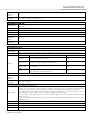
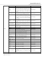
Drive - Velocity Limits - Velocity Limit Mode
Specifies the method for limiting the motor velocity within the motor's rated maximum velocity. The drive will
Description
never exceed the motor's rated maximum velocity. This setting can be used to restrict the motor velocity further.
Parameter
[Ft – 2.13]
Select
Description
Value
Range:
Disabled
Motor‟s rated maximum velocity
0x0
Manual Limit
Limited by "Manual Velocity limit" (Ft-2.12).
0x1
Analog Input
Limited by Analogue Speed Command Value (except Analog
Speed Mode).
0x2
Limited by lesser one between "Manual Velocity limit" (Ft2.12) and Analogue Speed Command.
0x3
Manual
Analog
Default:
Applicable
Operating
Mode
When
Enabled
and
Disabled
All
Servo-Off -> Setting
Description:
• Limits the operation speed to below this set value in all control modes. .
• There are two methods of speed limitation: limitation thorough this value and limitation through speed
command of upper level controller. Configure by referring to speed limit method selection of [Ft-2.13].
• In addition, in torque control mode, the mode is changed automatically to speed control mode if motor
speed exceeds this value; speed control is performed using limit speed command.
• If the analog speed command exceeds motor‟s maximum speed, the excessive speed command warning
“OSC” is issued.
• If excessive speed command warning is issued, the speed command is automatically reduced to the motor‟s
maximum speed.
Parameter:
Range:
Default:
[Ft – 2.12]
1~6000
5000
Units:
RPM for rotary motors, mm/sec for linear motors
RSWare User Manual
Applicable
Operating
Mode:
When Enabled
Follower, Analog Velocity, Preset
Servo-Off -> Setting
Drive -Acceleration Limits-Acceleration Limits
Sets the state of the Acceleration and Deceleration Limits in the drive, for the Analog Velocity and Preset
Description
Velocity operation modes.
Parameter:
Select
Description
Value
Range:
Default:
Applicable
Operating
Mode
When
Enabled
Inactive
Inactive
-
Active
Active
Active
-
All
Servo-Off -> Setting
Description:
Parameter:
Range:
Default:
Units:
Applicable
Operating
Mode:
When
Enabled
Acceleration means slope of the Speed Profile.
[Ft – 2.02]
0.01 ~ 21,474,836.47for rotary,1~2147483647 for linear
416.67for rotary, 41667 for linear
Rev/sec2 for rotary, mm/sec2 for linear
Description:
Parameter:
Range:
Default:
Units:
Applicable
Operating
Mode:
When
Enabled
Deceleration means slope of the Speed Profile.
[Ft – 2.03]
0.01 ~ 21,474,836.47for rotary,1~2147483647 for linear
416.67for rotary, 41667 for linear
Rev/sec2 for rotary, mm/sec2 for linear
Analog Velocity Input, Preset Velocity
Immediately
Analog Velocity Input, Preset Velocity
Immediately
RSWare User Manual
S-operation time set for smooth operation
• Applied only when acceleration/deceleration time have been set. If value is set to „0‟, S-operation is not
performed; if a value other than „0‟ is set, S-operation is performed on acceleration/ deceleration.
Description:
Parameter:
Range:
Default:
Units:
Applicable
Operating
Mode:
When
Enabled
[Ft – 2.04]
0~5000
0
ms
All
Immediately
Drive - Communications - Drive Address
Description:
The drive's communication port address
Parameter:
[Ft – 0.07]
Range:
1~247
Default:
1
Applicable
Operating
All
Mode
When
Immediately
Enabled
Description
Parameter
Range:
Default:
Applicable
Operating
Mode
When
Select the motor‟s rotation direction
[Ft – 0.02]- Digit 2
Select
Description
The command signal is not inverted so that a positive
Normal
command value results in CW Rotation, (as viewed from
shaft end).
The command signal is inverted so that a positive command
Inverted
value results in CCW Rotation, (as viewed from shaft end).
Normal
All
Servo-Off -> Setting
RSWare User Manual
Value
0x0
0x1
Enabled
Description
Parameter
Range:
Default:
Applicable
Operating
Mode
When
Enabled
Description
Parameter
Range:
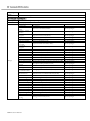
Select a baud rate for the drive.
Note: This parameter is supported for CSD5 drive. There are two types of Baudate for KNX3 Drive. RS-485
Port Baudrate and RS-232C Port Baudrate should be selected respectively.
[Ft – 0.09]- Digit 0
Select
Description
Value
9600bps
9600bps
0x0
14400bps
14400bps
0x1
19200bps
19200bps
0x2
38400bps
38400bps
0x3
56000bps
56000bps
0x4
57600bps
57600bps
0x5
57600bps
All
Immediately
Select the drive's communications port packet framing format.
[Ft – 0.09]- Digit 1
Select
Description
Value
8 Data, No Parity, 1 Stop bit
8, No, 1
0x0
8 Data, Even Parity, 1 Stop bit
8, Even, 1
0x1
8 Data, Odd Parity, 1 Stop bit
8, Odd, 1
0x2
8 Data, No Parity, 2 Stop bit
8, No, 2
0x3
8 Data, Even Parity, 2 Stop bit
8, Even, 2
0x4
8 Data, Odd Parity, 2 Stop bit
8, Odd, 2
0x5
Default:
Applicable
Operating
Mode
When
Enabled
8 Data, No Parity, 1 Stop bit
Description
Parameter
Select the drive‟s communications protocol
[Ft – 0.09]- Digit 2
Select
Description
ASCII
ASCII
MODBUS-RTU
MODBUS-RTU
ASCII
Range:
Default:
Applicable
Operating
Mode
When
Enabled
All
Immediately
All
Immediately
RSWare User Manual
Value
0x0
0x1
Description
Parameter
Select the drive‟s communications Method. Note: This parameter is only supported for CSD5 drive.
[Ft – 0.09]- Digit 3
Select
Description
Value
Range:
RS232
RS232
0x0
RS485
RS232
RS485
0x1
Default:
Applicable
Operating
Mode
When
Enabled
Description
Parameter
Range:
Default:
Applicable
Operating
Mode
When
Enabled
Description
Parameter
Range:
Default:
Applicable
Operating
Mode
When
Enabled
All
Immediately
It is used for selection of run-xx or Input function using Modbus. Run function cannot be used by key pad,
similarly, if the run function is used by Modbus. Note: This parameter is only supported for CSD5 drive.
[Ft – 0.32]- Digit 1
Select
Description
Value
Disable
Not use both Run and Input function by Modbus
0x0
Enable
Use run function only
0x1
Disable
All
Servo-Off -> Setting
It is used for selection of Input function using Modbus. Input function on Hardware cannot be used in case
that the input function is used by Modbus with this parameter. Note: This parameter is only supported for
CSD5 drive.
[Ft – 0.32]- Digit 0
Select
Description
Value
Disable
Not use both Run and Input function by Modbus
0x0
Enable
Use Input function only
0x1
use both Run and Input function by Modbus
0x2
Disable +
Function
Disable
Special
All
Servo-Off -> Setting
Drive - Current Limits - Positive Internal
Description
It limits positive torque in [%] unit related to rated torque. (internally limited)
Parameter
[Ft – 4.01]
Range:
0~500
Default:
300
RSWare User Manual
Units:
Applicable
Operating
Mode:
When
Enabled
% of motor rated continuous current
Description
Parameter
Range:
Default:
Units:
Applicable
Operating
Mode:
When
Enabled
It limits positive torque in [%] unit related to rated torque. (Internally limited)
[Ft – 4.02]
0~500
300
% of motor rated continuous current
All
Immediately
All
Immediately
• The torque imposed on the motor is internally limited automatically by the values set on [Ft-4.01], [Ft-4.02].
Additionally, it is also limited by the values set on [Ft-4.03], [Ft-4.04] when external </P-TL>, </N-TL>
signals are input through sequence input.
• The torque limit according to internal limit [Ft-4.01] and [Ft-4.01] takes precedence to external torque limit
</P-TL> and </N-TL> signals.
• If </P-TL> is ON, it limits positive torque in [%] unit related to rated torque.
Description
Parameter
Range:
Default:
Units:
Applicable
Operating
Mode:
When
Enabled
[Ft – 4.03]
0~500
100
% of motor rated continuous current
Description
Parameter
Range:
Default:
Units:
If </N-TL> is ON, it limits negative torque in [%] unit related to rated torque.
[Ft – 4.04]
0~500
100
% of motor rated continuous current
All
Immediately
RSWare User Manual
Applicable
Operating
Mode:
When
Enabled
Description
Parameter
All
Immediately
Select the software overtravel monitor enablement.
[IN 00.04]
Select
Description
Value
Off
Turns off software overtravel limit checking
0x0
On
Causes the drive to compare the motor feedback
position to the Positive and Negative Software Limits,
below, to determine if the drive has exceeded an
overtravel limit.
0x1
Range:
Default:
Applicable
Operating
Mode
When
Enabled
Off
Description
Parameter
If the motor feedback position is greater than this value, the drive has exceeded the software overtravel limit.
[IN 00.05]
Range:
-2,147,483,647~2,147,483,647
Default:
Applicable
Operating
Mode
When
Enabled
2,147,483,647
Description
Parameter
If the motor feedback position is less than this value, the drive has exceeded the software overtravel limit
[IN 00.06]
Range:
-2,147,483,647~2,147,483,647
Default:
Applicable
Operating
Mode
When
Enabled
-2,147,483,647
Description
Parameter
The stopping distance used when the drive encounters a positive overtravel limit.
[IN 00.02]
Range:
0~2,147,483,647
Default:
Applicable
Operating
Mode
When
Enabled
0
Indexing
Disable drive
Indexing
Disable drive
Indexing
Disable drive
Indexing
Always
RSWare User Manual
Description
Parameter
The stopping distance used when the drive encounters a negative overtravel limit.
[IN 00.03]
Range:
0~2,147,483,647
Default:
Applicable
Operating
Mode
When
Enabled
0
Indexing
Always
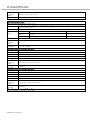
Drive -Speed Functions - Speed Window
If the speed error < Speed Window for 10 ms and the Within Speed Window output signal is assigned, then the
Description
Within Speed Window output is turned ON
Parameter
[Ft-5.03]
Range:
0-1000
Default:
Units:
Applicable
Operating
Mode:
When
Enabled
10
RPM for rotary motors, mm/sec for linear motors
Follower, Analog Velocity Input, Preset Velocity
Immediately
Parameter
If the motor speed > Up to Speed and the Up to Speed output signal is assigned, then the Up to Speed output
is turned ON.
[Ft-5.04]
Range:
1~5000
Default:
Units:
Applicable
Operating
Mode:
When
Enabled
20
RPM for rotary motors, mm/sec for linear motors
Description
All
Immediately
Parameter
If the Analog Speed Command < Zero Clamp, then the analog speed command is ignored and the motor
command speed is set to zero.
[Ft-5.05]
Range:
0~5000
Default:
Units:
Applicable
Operating
Mode:
When
Enabled
0
RPM for rotary motors, mm/sec for linear motors
Description
Analog Velocity
Immediately
RSWare User Manual
Parameter
If position error < In Position Size for 1 ms and the In Position Size output signal is assigned, the In Position
output is turned ON.
[Ft-5.00]
Range:
0~2500
Default:
Units:
Applicable
Operating
Mode:
When
Enabled
10
Counts
Description
Follower
Immediately
Parameter
If position error < Near Position Size and the Near Position output signal is assigned, the Near Position output
is turned ON
[Ft-5.02]
Range:
0~2500
Default:
Units:
Applicable
Operating
Mode:
When
Enabled
20
Counts
Description
Follower
Immediately
Drive - Motor Encoder Units - Position Label
When User is selected for Displayed Units, above, this is the user-defined label for position values relating to
Description
the motor encoder.
Parameter
Range:
Limited to 16 characters in length
Default:
Units:
Applicable
Operating
Mode:
When
Enabled
Counts
All
Immediately
Parameter
When User is selected for Displayed Units, above, this is the user-defined conversion factor used to convert
position values, relating to the motor encoder, into user units. In Counts per User Unit.
-
Range:
-
Default:
Units:
Applicable
Operating
Mode:
When
Enabled
1
In Counts per User Unit
Description
Description
All
Immediately
When User is selected for Displayed Units, above, this is the user-defined label for velocity values relating to
the motor encoder.
RSWare User Manual
Parameter
Range:
Limited to 16 characters in length
Default:
Units:
Applicable
Operating
Mode:
When
Enabled
RPM
All
Immediately
Parameter
When User is selected for Displayed Units, above, this is the user-defined conversion factor used to convert
velocity values, relating to the motor encoder, into user units. In Counts per second per User Unit.
-
Range:
-
Default:
Units:
Applicable
Operating
Mode:
When
Enabled
1
RPM
Description
All
Immediately
Parameter
When User is selected for Displayed Units, above, this is the user-defined label for acceleration values relating
to the motor encoder. Limited to 16 characters in length.
-
Range:
-
Default:
Units:
Applicable
Operating
Mode:
When
Enabled
Revs/s/s
Description
All
Immediately
Parameter
When User is selected for Displayed Units, above, this is the user-defined conversion factor used to convert
acceleration values, relating to the motor encoder, into user units. In Counts per second squared per User Unit.
-
Range:
-
Default:
Units:
Applicable
Operating
Mode:
When
Enabled
1
Revs/s^2 per User Units
Description
All
Immediately
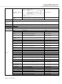
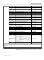
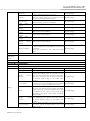
Drive - Stopping Functions - Over Travel Stop Method
Description
Set stopping current with Over travel Current limit parameter
Parameter
[Ft-0.02]-Digit 1
Range:
Select
Description
RSWare User Manual
Value
Default:
Applicable
Operating
Mode
When
Enabled
Current Control
Stop the motor while continuing the normal torque
control.
0x0
Dynamic Brake
Stops at
0x1
"Dynamic Brake" in the mode selected
Current Control
All
Servo-Off -> Setting
Parameter
•Limits the torque imposed on the motor if the motor is halted by overtravel (<P-OT>,<N-OT>) input signal
during rotation.
•Unlike external and internal torque limit, the torque limit value for overtravel input is same for forward and
reverse direction.
[Ft-4.05]
Range:
0~500
Default:
Units
Applicable
Operating
Mode
When
Enabled
300
% of motor rated continuous current
Description
Parameter
Set the Dynamic Brake(DB) stop method
[Ft-0.02]-Digit 0
Select
Description
Value
Brake and hold
DB stop is maintained even after the complete stop.
0x0
Brake and release
DB Stop. DB operation is released after the complete
stop.
0x1
Free stop
The DB is not used, but free run stop.
0x2
Free stop and hold
Free run stop. DB operation is maintained after the
complete stop.
0x3
Description
Range:
Default:
Applicable
Operating
Mode
When
Enabled
All
Immediately
Brake and hold
All
Servo-Off -> Setting
Parameter
Disable Delay is the time from when Drive Disable command is received to when the Drive Disable command
is actually executed.
[Ft-5.07]
Range:
0~10000
Default:
Units:
Applicable
Operating
Mode:
When
0
ms
Description
All
Servo-Off -> Setting
RSWare User Manual
Enabled
Parameter
The Braking Application Speed is the feedback speed below which the motor break is engaged, after disabling
the drive.
[Ft-5.09]
Range:
0~10000
Default:
Units:
Applicable
Operating
Mode:
When
Enabled
100
RPM for rotary motors, mm/sec for linear motors
Description
All
Servo-Off -> Setting
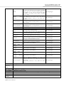
Drive - Auxiliary Function Selection 1- Velocity Observer
Selection of velocity monitor use, When high resolution encoder is used by activating velocity monitor, the
Description
speed ripple occurring at low velocity operation can be reduced.
Parameter
[Ft-0.05]-Digit 1
Select
Description
Value
Range:
Disable
Disable
0x0
Enable
Enable
0x1
Default:
Applicable
Operating
Mode
When
Enabled
Disable
Description
Parameter
Select the emergency stop input enablement
[Ft-0.05]-Digit 3
Select
Description
Value
Disable
Disable
0x0
Enable
Enable
0x1
Range:
Default:
Applicable
Operating
Mode
When
Enabled
All
Servo-Off -> Setting -> After power cycle
Disable
All
Servo-Off -> Setting -> After power cycle
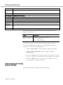
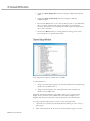
The following statuses are displayed by default for an CSD5 drive in the OnLine Drives branch of the Workspace window:
Note: All ON statuses have a value of 1; all OFF statuses have a value of 0.
Current Operating Mode
RSWare User Manual
ON indicates the current of operating mode setting.
Within Position Window
ON indicates position error has been less than the In
Position Size setting for longer than the In Position
Time setting.
Up to Speed
ON indicates motor velocity feedback is greater than
the Up To Speed setting.
Fault/Warning
Positive Overtravel
Negative Overtravel
If no error, it indicates "no error".
ON indicates positive overtravel limit sensor is
detected or position feedback exceeds positive
software overtravel limit in case of using indexing
mode.
ON indicates negative overtravel limit sensor is
detected or position feedback exceeds negative
software overtravel limit in case of using indexing
mode.
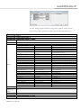
The following commands can be executed for an CSD5 Drive window that is
located in the On-Line Drives branch. These commands are explained in the
following sections:
Velocity Control Panel
Opens the Velocity Control Panel window. Refer to
Velocity Control Panel Window on page 44 for more
information about how to set a drive's velocity
command and monitor its motor velocity or current.
Reset Drive
Resets, or reboots, the hardware and firmware for a
drive.
Reset to Factory settings
Resets a drive's parameters by reinitializing them to
factory default settings. Stored faults and the Time in
Service clock remain unchanged
Save parameters
Save parameters
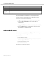
Customize the window for your CSD5 Drive branch by selecting one or more
of the following buttons:
• Toggle the Show Status selection to display or hide the Status pane.
• Toggle the Show Commands selection to display or hide the
Commands pane.
• Click on the Setup button to open the Monitor Setup window as shown
on page 112, where you can customize the status display for this window.
• Click on the Revert button to return parameter settings to the values
they held when you opened this window.
The Properties window for the Velocity Control Panel looks like this:
RSWare User Manual
Note: The command buttons (Jog Forward/Reverse/Enable/Disable) can be
displayed for CSD5 Drive window that is located in the On-Line Drive branch.
Use the Velocity Control Panel window to directly set the drive's velocity
command. In support of these functions, you can also:
• Jog Forward/Jog Reverse
• Jog /Enable or Jog/Disable
The commands you execute override any motion commands originating from
the drive's normal operation mode, set in the CSD5 Drive window.
The Velocity Control Panel commands override the normal
operation mode. The motor moves in response to Velocity
Control Panel commands!
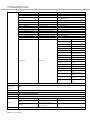
The Velocity Control Panel has the following parameters, statuses and direct
commands:
Parameter
Sets speed for jog operation using (run-00).
The speed, at which the motor turns when the Velocity Mode command executes, provided that the drive is
on-line and enabled.
Note: The drive ramps up, or ramps down, to the commanded velocity at the rate of acceleration set in the
Acceleration input box.
[Ft-2.01]
Range:
0~6000
Default:
Units:
Applicable
Operating
Mode:
When Enabled
50
RPM for rotary motors, mm/sec for linear motors
Description
All
Immediately
The following commands can be executed from the Velocity Control Panel
window of an on-line drive:
RSWare User Manual
Jog Forward
Move forward direction
Jog Reverse
Move reverse direction
Jog Enable
Enables the power stage of a drive
Jog Disable
Disables the power stage of a drive.
Customize the Velocity Control Panel window for your CSD5 Drive by
selecting one or more of the following buttons:
• Toggle the Show Commands selection to display or hide the
Commands pane.
• Click on the Revert button to return parameter settings to the values
they held when you opened this window.
The Properties window for the Analog branch looks like this:
Note: The Properties window for Analog of CSD5 Drive and KNX3 Drive are
not same. The below is an illustration of CSD5 Drive.
Use the Analog window to:
• set Analog Velocity, Current and Command Input drive parameters for
an on-line or off-line drive,
• monitor the status of the incoming Analog Command for an on-line
drive, and
• execute commands that remove Velocity, Current and Input Offsets for
an on-line drive.
These parameters govern drive operations when the Operating Mode is set to
Analog Velocity Input, or Analog Current Input, in the window.
RSWare User Manual
Drive - Mode Configuration - Analog- Velocity Scale
• Sets the speed command value[rpm] for the analog speed command input pin(Pin 19,20 of I/O)
Description
• Speed command[rpm] = Ft-2.00 [rpm/V] x Input voltage[V]
Parameter
[Ft-2.00]
Range:
10.0~2000.0
Default:
Units:
Applicable
Operating
Mode:
When
Enabled
500.0
RPM/V for rotary motors, mm/sec for linear motors
Analog Velocity
Servo-Off -> Setting
Parameter
• Set the speed command value[%] for 1[V] on the analog torque command input pin(pin 21,22 of I/O)
• Torque command[%] = [Ft-4.00] [%/V] x input voltage[V]
[Ft-4.00]
Range:
0-100
Default:
Units:
Applicable
Operating
Mode:
When
Enabled
33.3
% of motor rated continuous current/Volt
Description
Parameter
The drive's velocity input offset value. This value indicates the offset of the Analog Command Input.
-10,000~10,000
Description
Range:
Analog Current Command, Dual Current Command
Servo-Off -> Setting
Default:
Units:
Applicable
Operating
Mode:
When
Enabled
0.0
mV
Analog Velocity Command
Description
Parameter
The drive's current input offset value. This value indicates the offset of the Analog Command Input.
-10,000~10,000
Range:
Default:
Units:
Applicable
Operating
Mode:
When
Enabled
Servo-Off -> Setting
0.0
mV
Analog Velocity Command
Servo-Off -> Setting
You can edit Analog parameters for both an on-line and an off-line drive.
However, you can monitor statuses and execute direct commands (i.e.,
RSWare User Manual
executed through the RSWare interface) only for a Analog window that is the
child of an on-line drive.
The following status is displayed by default for an Analog window of an on-line
drive:
Analog Command - Velocity
External Analog Velocity Command
Analog Command - Current
External Analog Current Command
Command Velocity
Actual Velocity Command
Command Current
Actual Current Command
The following commands can be executed for an Analog window that is located
in the On-Line Drives branch:
Remove Velocity Input
Offset
This command automatically measures the existing
offset of the Analog Command Input, and resets the
Velocity Offset value to eliminate the offset.
Remove Current Input
Offset
This command automatically measures the existing
offset of the Analog Command Input, and resets the
Current Offset value to eliminate the offset.
Save parameters
Save parameters
Customize the Analog window for your CSD5 Drive branch by selecting one or
more of the following buttons:
• Toggle the Show Status selection to display or hide the Status pane.
• Toggle the Show Commands selection to display or hide the
Commands pane.
• Click on the Setup button to open the Monitor Setup window as shown
on page 112, where you can customize the status display for this window.
• Click on the Revert button to return parameter settings to the values
they held when you opened this window.
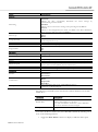
The Properties window for Presets looks like this:
RSWare User Manual
Use the Preset window to configure:
• up to seven preset velocity values
Preset parameters control drive operation when the Operating Mode is set to
Preset Velocity in the CSD5 Drive window.
The drive uses the preset velocity value selected by the Preset Select Lines 0, 1
and 2 as set in the Digital Inputs properties window.
The digital input's Preset Select Line binary values are as follows:
• Preset Select 0 = 1 if active, 0 if not.
• Preset Select 1 = 2 if active, 0 if not.
• Preset Select 2 = 4 if active, 0 if not.
If a Preset Select Line is not assigned to a digital input, the Preset Select Line is
considered inactive.
If you only want to use a single gear ratio, simply set up the Gear Ratio for
Preset 0, and don't assign the Preset Select 0, 1 or 2 to any digital inputs.
Note: Binary values for an active digital input's Preset Select Lines 3, 4 and 5 do
not apply to this calculation.
The Preset window has no associated statuses or direct commands. The Preset
window has the following parameters:
Parameter
• Sets each contact speed commands for contact speed control mode
• The operation speed should be entered in advance into the relevant parameters </C-SP1>, </C-SP2>, </CSP3>.
• According to combination of the sequence input signals </C-SP1>, </C-SP2>, </C-SP3>, operation at
preset speed is possible.
• In addition, sequence input signal </C-DIR> is used to change the rotation direction of each speed
command.
• To reduce impact of speed change, set the acceleration/deceleration time to a sufficient value which should
not interfere with system responsiveness
[Ft-2.05]
Range:
-6000~6000
Description
RSWare User Manual
Default:
0
Units:
RPM for rotary motors, mm/sec for linear motors
Applicable
Operating
Preset
Mode:
When
Immediately
Enabled
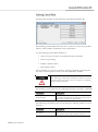
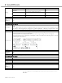
Table. Rotational speed depending on signals </C-SP1>, </C-SP2>, </C-SP3>.
Preset Velocity
Parameters
</C-SP3>
</C-SP2>
Stop Command
Preset Velocity 1
0(rpm)
Ft- 2.05
0
0
0
0
0
1
Preset Velocity 2
Preset Velocity 3
Preset Velocity 4
Preset Velocity 5
Preset Velocity 6
Ft- 2.06
Ft- 2.07
Ft- 2.08
Ft- 2.09
Ft- 2.10
0
0
1
1
1
1
1
0
0
1
0
1
0
1
0
Preset Velocity 7
Ft- 2.11
1
1
1
Description
Parameter
Refer to description of [Ft-2.05]
[Ft-2.06]
Range:
-6000~6000
Default:
Units:
Applicable
Operating
Mode:
When
Enabled
0
RPM for rotary motors, mm/sec for linear motors
Description
Parameter
Refer to description of [Ft-2.05]
[Ft-2.07]
Range:
-6000~6000
Default:
Units:
Applicable
Operating
Mode:
When
Enabled
0
RPM for rotary motors, mm/sec for linear motors
Description
Parameter
Refer to description of [Ft-2.05]
[Ft-2.08]
Range:
-6000~6000
Default:
Units:
Applicable
Operating
Mode:
When
0
RPM for rotary motors, mm/sec for linear motors
Preset
Immediately
Preset
Immediately
Preset
Immediately
RSWare User Manual
</C-SP1>
Enabled
Description
Parameter
Refer to description of [Ft-2.05]
[Ft-2.09]
Range:
-6000~6000
Default:
Units:
Applicable
Operating
Mode:
When
Enabled
0
RPM for rotary motors, mm/sec for linear motors
Description
Parameter
Refer to description of [Ft-2.05]
[Ft-2.10]
Range:
-6000~6000
Default:
Units:
Applicable
Operating
Mode:
When
Enabled
0
RPM for rotary motors, mm/sec for linear motors
Description
Parameter
Refer to description of [Ft-2.05]
[Ft-2.11]
Range:
-6000~6000
Default:
Units:
Applicable
Operating
Mode:
When
Enabled
0
RPM for rotary motors, mm/sec for linear motors
Preset
Immediately
Preset
Immediately
Preset
Immediately
Click on the Revert button to return parameter settings to the values they held
when you opened this window.
The Properties window for Followers looks like this:
RSWare User Manual
Follower parameters control drive operation when the Operating Mode is set to
one of the following:
• Step Up/Step Down. Positive Logic
• Step Up/Step Down. Negative Logic
• Step/Direction. Positive Logic
• Step/Direction. Negative Logic
• Auxiliary Encoder. X1
• Auxiliary Encoder. X2
• Auxiliary Encoder. X4
in the CSD5 Drive window.
The Follower window has no associated statuses or direct commands. The
Follower window has the following parameters:
Description
Parameter
Range:
Note: For Command types 0x4, 0x5, and 0x6:
Motor Counts = Master Lines * MULT * ……
….. (4 * Para3.01) / Para3.02
where MULT is 1, 2 or 4 for command types 0x4, 0x5 and 0x6 respectively.
[Ft-3.00]-Digit0
Select
Description
Step Up/Step Down, Positive logic
Step Up/Step Down, Positive logic
Step Up/Step Down, Negative logic
Step Up/Step Down, Negative logic
Step/Direction, Positive Logic
Step/Direction, Positive Logic
Step/Direction, Negative Logic
Step/Direction, Negative Logic
Auxiliary Encoder, x1
A phase + B phase, x1
Auxiliary Encoder, x2
A phase + B phase, x2
Auxiliary Encoder, x4
A phase + B phase, x4
Step Up/Step Down, Positive logic
Default:
Applicable
Operating
Follower
Mode
When
Servo-Off -> Setting
Enabled
Drive - Mode Configuration - Follower - Controller Output Type
RSWare User Manual
Value
0x0
0x1
0x2
0x3
0x4
0x5
0x6
Description
Parameter
Range:
Default:
Applicable
Operating
Mode
When
Enabled
Description:
Parameter
Range:
Default:
Applicable
Operating
Mode:
When
Enabled
Description:
Parameter
Range:
Default:
Units:
Applicable
Operating
Mode:
When
Enabled
Description:
Parameter
Range:
Default:
Select the host controller output type
[Ft-3.00]-Digit1
Select
Description
Use Low speed Line Drive Output in Host Controller
Line Drive Input
for isolated electrical connection. (900kHz Max)
Use Open Collector in Host Controller. (250kHz
Open Collector Input
Max)
High Frequency Line Use High Frequency Line Drive Output in Host
Drive Input
Controller.(3MHz Max)
Line Drive Input
Value
0x0
0x1
0x2
Follower
Servo-Off -> Setting
Select the drive state to make 1st gear ratio take effect
[Ft-3.00]-Digit3
Select
Description
Enable Only on Drive Disabled
Enable Only on Drive Disabled
Always Enable
Always Enable
Enable Only on Drive Disabled
Value
0x0
0x1
Follower
Servo-Off -> Setting
• Denominator of Electronic gear([Ft-3.01])
• Numerator of Electronic gear([Ft-3.02])
• By using the electronic gear function, the amount of motor rotation pr input command pulse can be set
arbitrarily.
• The following relationship has to be satisfied: No. of pulses per 1 motor rotation x Reduction ratio x 4 (Pr3.02)
• Maximum resolution=1/ ([No.of pulses per 1 motor rotation] x [Reduction ratio] x 4)
[Ft-3.01]( Denominator of Electronic gear), [Ft-3.02]( Numerator of Electronic gear)
1~65535
360:10000
Master Counts : Follower Counts
Follower
Servo-Off -> Setting
• Denominator of 2nd Gear Ratio ([Ft-3.04])
• Numerator of 2nd Gear Ratio ([Ft-3.05])
• By using the electronic gear function, the amount of motor rotation pr input command pulse can be set
arbitrarily.
• The following relationship has to be satisfied: No. of pulses per 1 motor rotation x Reduction ratio x 4 (Ftr3.02)
• Maximum resolution=1/ ([No.of pulses per 1 motor rotation] x [Reduction ratio] x 4)
[Ft-3.04]( Denominator of 2nd Gear Ratio), [Ft-3.05]( Numerator of 2nd Gear Ratio)
1~65535
1:4
RSWare User Manual
Units:
Applicable
Operating
Mode:
When
Enabled
Master Counts : Follower Counts
Description
Parameter
The controller has differential TTL/CMOS outputs
[Ft-3.08]-Digit0
Select
Description
3.000
3.000 MHz
1.750
1.750 MHz
Range:
Default:
Applicable
Operating
Mode
When
Enabled
Description
Parameter
Range:
Default:
Applicable
Operating
Mode
When
Enabled
Description
Parameter
Range:
Follower
Servo-Off -> Setting
1.500
1.000
0.750
0.625
0.562
0.525
1.000
1.500 MHz
1.000 MHz
0.750 MHz
0.625 MHz
0.562 MHz
0.525 MHz
Value
0x0
0x1
0x2
0x3
0x4
0x5
0x6
0x7
All
Servo-Off -> Setting
The controller has single-ended transistor outputs
[Ft-3.08]-Digit1
Select
Description
3.000
3.000 MHz
1.750
1.750 MHz
1.500
1.500 MHz
1.000
1.000 MHz
0.750
0.750 MHz
0.625
0.625 MHz
0.562
0.562 MHz
0.525
0.525 MHz
0.525
Value
0x0
0x1
0x2
0x3
0x4
0x5
0x6
0x7
All
Servo-Off -> Setting
The controller has differential TTL/CMOS outputs
[Ft-3.08]-Digit2
Select
Description
3.000
3.000 MHz
1.750
1.750 MHz
1.500
1.500 MHz
RSWare User Manual
Value
0x0
0x1
0x2
Default:
Applicable
Operating
Mode
When
Enabled
1.000
0.750
0.625
0.562
0.525
3.000
1.000 MHz
0.750 MHz
0.625 MHz
0.562 MHz
0.525 MHz
0x3
0x4
0x5
0x6
0x7
All
Servo-Off -> Setting
Click on the Revert button to return parameter settings to the values they held
when you opened this window.
The Properties window for Indexing looks like this:
Note: The Properties window for Indexing of CSD5 Drive and KNX3 Drive
are not same. The below is an illustration of CSD5 Drive.
Use the Indexing window to:
RSWare User Manual
• configure up to sixty-four indexes (0 ~63)for CSD5 Drive.[ (0~6) for
KNX3 Drive], and
• open the Indexing Control Panel where you can:
-start and stop execution of the index command
-start and stop homing
-enable or disable a drive, and
-monitor the execution of an index.
An index controls drive operation by executing preconfigured motion
commands.
An index controls drive operation when Operating Mode is set to Indexing, in
the CSD5 Drive window. The drive uses the index whose number (0 ~63)
reflects the cumulative binary values of the Preset Select Lines 0, 1, 2, 3, 4 and 5,
that are selected in the Digital Inputs window.
The digital input Preset Select Line binary values are as follows:
• Preset Select 0 = 1 if active, 0 if not.
• Preset Select 1 = 2 if active, 0 if not.
• Preset Select 2 = 4 if active, 0 if not.
• Preset Select 3 = 8 if active, 0 if not.
• Preset Select 4 = 16 if active, 0 if not.
• Preset Select 5 = 32 if active, 0 if not
If a Preset Select Line is not assigned to a digital input, the Preset Select Line is
considered inactive.
The following parameters, statuses and commands apply to Indexing:
Description
Parameter
Range:
Default:
Applicable
Operating
Mode
When
Enabled
When this field is set to "on", the drive will begin executing the selected index whenever the drive enables.
[IN00.00]
Select
Description
Value
Drive starts to move to the selected
Off
index with start indexing input after 0x0
drive enable
Drive starts to move to the selected
On
index without start indexing input after 0x1
drive enable
Off
Indexing
Power Cycling
RSWare User Manual
Description
Parameter
The deceleration used to stop motion when the Stop Index input terminates an index move.
[IN00.01]
Range:
0.01~21474836.47 for rotary; 0.001~2147483.647 for linear.
Default:
Units:
Applicable
Operating
Mode
When
Enabled
62.50 for rotary,6.250for linear
*Rev/sec2 for rotary, mm/sec2 for linear
Indexing
Always
Parameter
This parameter is the user defined distance per motor 1 revolution in order to change the unit of indexing point
distance
[IN00.07]
Range:
0~99,999
Default:
Units:
Applicable
Operating
Mode
When
Enabled
0
User Defined
Description
Description
Parameter
Range:
Default:
Applicable
Operating
Mode
When
Enabled
Description
Parameter
Range:
Default:
Units:
Applicable
Operating
Mode
When
Enabled
Indexing
Power Cycling
Note: The axis must be homed before the drive can execute any index. The
available at Phase 2
[IN02.00~IN02.63]-Digit 0
Select
Description
Moves from its starting position to the specified
Absolute
Position, below.
Moves from its starting position the specified Distance,
Incremental
below.
Incremental
shaded “Registration” is not
Value
0x0
0x1
Indexing
Always
Position: For Absolute mode moves, the fixed position to which the motor will travel.
Distance: For Incremental and Registration mode moves, the relative distance the motor will travel.
[IN04.00~IN04.63]
-2,147,483,647~2,147,483,647
0
Counts
Indexing
Always
RSWare User Manual
Description
Parameter
Range:
Milliseconds to remain at current position before executing
[IN07.00~IN07.63]
0~65,535
Default:
Units:
Applicable
Operating
Mode
When
Enabled
0
ms
Description
Parameter
Range:
Maximum velocity while in motion.
[IN08.00~IN08.63]
0~6000 for rotary;0.000~6.000for liner
Default:
Units:
Applicable
Operating
Mode
When
Enabled
750 for rotary;0.750 for linear
RPM for rotary motors, mm/sec for linear motors
Description
Parameter
Range:
Maximum velocity while in motion.
[IN10.00~IN10.63]
0.01~21474836.47 for rotary; 0.001~2147483.647 for linear.
Default:
Units:
Applicable
Operating
Mode
When
Enabled
62.50 for rotary,6.250for linear
*Rev/sec2 for rotary, mm/sec2 for linear
Description
Parameter
Range:
Maximum deceleration while in motion
[IN11.00~IN11.63]
0.01~21474836.47 for rotary; 0.001~2147483.647 for linear.
Default:
Units:
Applicable
Operating
Mode
When
Enabled
62.50 for rotary,6.250for linear
*Rev/sec2 for rotary, mm/sec2 for linear
Description
Parameter
Range:
The number (0~63) of the next indexed move to execute when Action When Complete is not set to “Stop”.
[IN12.00~IN12.63]
0~63
Default:
Units:
Applicable
Operating
0
-
Indexing
Always
Indexing
Always
Indexing
Always
Indexing
Always
Indexing
RSWare User Manual
Mode
When
Enabled
Description
Parameter
Range:
Default:
Applicable
Operating
Mode
When
Enabled
Always
The drive's action when the index has completed.
[IN02.00~IN02.63]-Digit 1
Select
Description
Ends the execution of indexed move commands
Stop
(default setting).
Commands execution of the Next Index move without
Start next index
additional input, but after the scheduled Dwell.
Commands execution of the Next Index move the next
Wait for Start
time the Start Index input becomes active.
Stop
Value
0x0
0x1
0x2
Indexing
Always
The following statuses can be displayed from a Indexing window of an on-line
drive:
In Motion
In Dwell
Axis Homed
ON indicates the motor is moving in response to an indexed motion
command.
Note: The In Motion status has a value of 1 when ON, and 0 when
OFF.
ON indicates the motor is holding position and waiting the
commanded dwell time.
Note: The In Dwell status has a value of 1 when ON, and 0 when
OFF.
ON indicates that the homing routine has completed.
Note: The Axis Homed status has a value of 1 when ON, and 0
when OFF.
The following command can be executed from a Indexing window of an online drive:
Customize the Indexing window for your CSD5 Drive by selecting one or more
of the following buttons:
• Toggle the Show Status selection to display or hide the Status pane.
• Toggle the Show Commands selection to display or hide the
Commands pane
• Click on the Setup button to open the Monitor Setup window as shown
on page 112, where you can customize the status display for this window.
• Click on the Revert button to return parameter settings to the values
they held when you opened this window.
RSWare User Manual
The Properties window for the Indexing Control Panel looks like this:
The Indexing Control Panel allows the user to select one of sixty-four possible
indexes, and send direct commands to the selected drive.
Use the Indexing Control Panel window to:
• Start or stop the execution of an indexed motion command.
• Start or stop homing.
• Enable or disable a drive.
• Reset all drive faults.
The commands you execute override any motion commands originating from
the drive's normal operation mode, set in the CSD5 Drive window.
The Indexing Control Panel commands override the normal
operation mode. The motor moves in response to Indexing
Control Panel commands!
The Indexing Control Panel has the following parameter, and direct commands:
Index Number
The number (0 - 63) of the indexed motion
command, configured in the Indexing window, which
starts when you select the Start Index.
The following commands can be executed from the Indexing window of an online drive:
Start Index
RSWare User Manual
Begins execution of the indexed motion command (0
- 63) specified in the Index Number parameter.
Stop Index
Stops execution of the indexed motion command (0 63) specified in the Index Number parameter.
Start Homing
Begins execution of the homing sequence as defined
in the Homing window.
Stop Homing
Stops execution of the homing sequence.
Enable Drive
Enables the power stage of a drive.
Disable Drive
Disables the power stage of a drive.
Clear Faults
Clears all drive faults
Note: Closing the window returns the drive to its normal operating mode, but
software disabled. Select the drive and execute an Enable command and
instructed in the Windows' message to make the drive operational.
Customize the Indexing Control Panel window for your CSD5 Drive by
selecting one or more of the following buttons:
• Toggle the Show Status selection to display or hide the Status pane.
• Toggle the Show Commands selection to display or hide the
Commands pane
• Click on the Setup button to open the Monitor Setup window as shown
on page 112, where you can customize the status display for this window.
• Click on the Revert button to return parameter settings to the values
they held when you opened this window.
The Properties window for the Indexing Teaching Panel looks like this:
RSWare User Manual
• Indexing Teaching Panel is added from RSWare Version 1.2.0.
•
After the motor moved by the Jog operation, “Teaching save" button is
pressed, the current value of the Follower position is stored as the
Distance or Position parameters of selected index.
The Properties window for Homing looks like this:
RSWare User Manual
Use the Homing window to configure the type of homing operation the drive
performs.
Note: Homing operations are performed by issuing the Start Homing
command from the Indexing Control Panel.
Homing has no associated statuses. Except for Copy and Paste, it just has a
Save Parameters command.
Note: A homing operation is performed by issuing the Start Homing command
in the Indexing Control Panel.
The following parameters apply to Homing:
Description
Parameter
Range:
Select the type of homing operation the drive will perform
[IN01.00]
Select
Description
The position when a Start Homing signal is inputted
Home to Present becomes the new home. If the Auto Start Homing
Position
function is enabled, the position when the drive is
enabled becomes the new home
After the active-going
edge of the sensor is detected, the drive immediately
reverses motor direction and looks for the inactivegoing edge of the sensor. After the inactive-going edge
of the sensor is detected, the drive looks for the marker.
To
Home
After the marker is detected, the drive moves the motor
sensor/Back
to
the Offset Move Distance from the marker, reversing if
Marker
necessary. The final position becomes the new Home
position. The Homing Velocity is used for the initial
sensor search. After the motor decelerates to a stop
when it finds the active-going sensor edge, the Creep
Velocity is used for all the remaining motion.
This homing procedure is the same as the 'To Home
To Limit/Back to sensor / Back to Marker', only except that the physical
Marker
overtravel is used instead of home sensor input. The
physical overtravel fault is disabled while homing
RSWare User Manual
Value
0x0
0x1
0x2
After the active-going edge of the sensor is detected,
the drive looks for the marker. After the marker is
detected, the drive moves the motor the Offset Move
Distance from the marker, reversing if necessary. The
final position becomes the new Home position.
The homing procedure is the same as the 'To Home
To Limit/Fwd to sensor / Fwd to Marker ', only except that the physical
Marker
overtravel is used instead of home sensor input. The
physical overtravel fault is disabled while homing
The drive moves the motor at the Homing Velocity
until the feedback current reaches the Home Current
Home to Current Value. After the Home Current Value is hit, the drive
Value
immediately stops the motor motion and moves the
Offset Move Distance, reversing if necessary. The final
position becomes the new Home position
After the Home Current Value is reached, the drive
immediately reverses motor direction and looks for the
marker. After the marker is detected, the drive moves
Home to Current the motor the Offset Move Distance from the marker,
Value/Back to Marker reversing if necessary. The final position becomes the
new Home position. The Homing Velocity is used for
the initial motion until the current value is reached. The
Creep Velocity is used for all the remaining motion.
Sometimes, the distance is very short between home
sensor and marker, so it may miss to detect the first
marker. To prevent this, this method has one more
parameter to define a minimum distance to detect
To
Home
Marker. The minimum distance is defined as a time in
sensor/Move/Fwd to
the „moving distance after home sensor‟. After it detects
Marker
the home sensor input, the velocity is decelerated to the
creep velocity and it is maintained until the marker is
detected. After the marker is detected, the motor move
back to the position
After the marker is detected, the drive moves the motor
the Offset Move Distance from the marker, reversing if
Home to Marker
necessary. The final position becomes the new Home
position.
To Home Sensor/Back to Marker
To
sensor/Fwd
Marker
Default:
Applicable
Operating
Mode
When
Enabled
Description
Parameter
Range:
Default:
Applicable
Operating
Mode
When
Enabled
Home
to
0x3
0x4
0x5
0x6
0x7
0x8
Indexing
Disable drive
Causes the drive to begin the homing procedure automatically when the drive is enabled.
[IN01.01]
Select
Description
Value
Automatically starts homing every time the drive is
Active:
0x0
enabled.
Automatically starts homing when a drive is
Active After Reset Only
0x1
enabled, if the drive has not already been homed
Inactive
Starts homing with start homing input
0x2
Inactive
Indexing
Power Cycling
RSWare User Manual
Parameter
The commanded velocity used during homing. The sign of this value (+/-) indicates the direction of motion
during homing.
[IN01.02]
Range:
-6,000~6,000
Default:
Units
Applicable
Operating
Mode
When
Enabled
100
RPM for rotary motors, mm/sec for linear motors
Description
Parameter
The rate of acceleration and deceleration used during homing
[IN01.04]
Range:
62.50
Default:
Units
Applicable
Operating
Mode
When
Enabled
100
Rev/sec2 for rotary, mm/sec2 for linear
Description
Indexing
Disable drive
Indexing
Disable drive
Parameter
The distance the motor position will be from the marker edge (or sensor edge for Sensor only Homing Type)
after the homing sequence is complete.
[IN01.05]
Range:
-2,147,483,647~2,147,483,647
Default:
Units
Applicable
Operating
Mode
When
Enabled
0
Counts
Description
Parameter
The rate of drive deceleration used when homing is stopped.
[IN01.12]
Range:
1~2,147,483,647
Default:
Units
Applicable
Operating
Mode
When
Enabled
6250
Rev/sec2 for rotary, mm/sec2 for linear
Description
Parameter
Range:
Specifies the digital input state which indicates to the drive that the Home Sensor input is active
[IN01.06]
Select
Description
Value
Description
Indexing
Disable drive
Indexing
Disable drive
RSWare User Manual
Default:
Applicable
Operating
Mode
When
Enabled
Active- Going Transition
Inactive- Going Transition
Inactive
Active- Going Transition
Inactive- Going Transition
Indexing
Power Cycling
Description
Parameter
The home position when a homing procedure is completed.
[IN01.07]
Range:
-2,147,483,647~2,147,483,647
Default:
Units
Applicable
Operating
Mode
When
Enabled
0
Counts
Description
Parameter
Range:
Default:
Units
Applicable
Operating
Mode
When
Enabled
Description
Parameter
Range:
Default:
Units
Applicable
Operating
Mode
When
Enabled
0x0
0x1
Indexing
Disable drive
For the To Sensor, then Back to Marker Homing Type, the velocity used for all remaining homing motion after
the motor decelerates to a stop when it finds the sensor edge.
[IN01.03]
0~6,000
20
RPM for rotary motors, mm/sec for linear motors
Indexing
Disable drive
Specifies the torque feedback at which the drive stops moving the motor at the Homing Velocity.
Unit : Percentages of a motor rating torque
[IN01.09]
1~250
100
%
Indexing
Disable drive
Description
Parameter
This value is distance that the drive ignores the marker inputs after the home sensor is detected.
[IN01.08]
Range:
0~2,147,483,647
Default:
Units
Applicable
Operating
Mode
0
Counts
Indexing
RSWare User Manual
When
Enabled
Disable drive
Description
Parameter
The time to when the torque feedback is more than the home current to when the drive detects stopper.
[IN01.10]
Range:
0~1,000
Default:
Units
Applicable
Operating
Mode
When
Enabled
0
ms
Description
Parameter
Drive fault occurs when time for homing is over the homing time limit.
[IN01.11]
Range:
0~65,535
Default:
Units
Applicable
Operating
Mode
When
Enabled
60
sec
Indexing
Disable drive
Indexing
Disable drive
The following statuses can be displayed from a Homing window of an on-line
drive:
In Motion
ON indicates the motor is moving in response to an indexed motion
command.
Note: The In Motion status has a value of 1 when ON, and 0 when
OFF.
In Dwell
ON indicates the motor is holding position and waiting the
commanded dwell time.
Note: The In Dwell status has a value of 1 when ON, and 0 when
OFF.
Axis Homed
ON indicates that the homing routine has completed.
Note: The Axis Homed status has a value of 1 when ON, and 0
when OFF.
Customize the Homing window for your CSD5 Drive by selecting one or more
of the following buttons:
• Toggle the Show Status selection to display or hide the Status pane.
• Click on the Revert button to return parameter settings to the values
they held when you opened this window.
RSWare User Manual
The Properties window for Motors looks like this:
Note: The Properties window for Motors of CSD5 Drive and KNX3 Drive are
not same. The below is an illustration of CSD5 Drive.
Use the Motor window to:
• Select a motor for the associated on-line or off-line CSD5 drive. Once
you select a motor, the status values associated with the selected motor
appears in the Status pane of this window.
• Monitor the statuses that relate to the selected motor.
The following parameters, statuses and commands apply to motors:
Description
Parameter
Select the type of homing operation the drive will perform
[Ft-0.06]- Digit 0
RSWare User Manual
Select
Description
Causes the drive to read motor parameters
from a Motor Model selected, below.
Disabled
Value
0x0
Range:
Causes the drive to read motor parameters
from an intelligent encoder
Enabled
Default:
Applicable
Operating
Mode
When Enabled
Description
Parameter
0x1
Disabled
All
Immediately
(Only if Auto Motor Iden is disabled.) The model name of the selected motor. Only listed motor models are
valid.
Note: RSWare ships with a Motor Configuration utility that lets you create custom motor configurations. Use
that utility to add customized motor selections to the Motor Model list, by clicking on the Start button, then
selecting Programs, OEMax Software, RSWare and Motor Configuration from the pop-up menus.
[Ft-0.01]
•Set three items of the motor: motor type, motor rated output, and encoder type.
•check the model name on the motor nameplate.
•Press Up/Down arrow keys, alphabetic and numeric characters representing each mode is displayed.
•The following figure is an example of the nameplate on the motor. Refer to the following figure to set the
predefined place for each items.
Setting Value:
Default:
Applicable
Operating
Mode
When Enabled
All
Description
Parameter
Load Inertia / Motor Inertia
[Ft-0.04]
Range:
0~6000
Default:
Units:
Applicable
Operating
Mode
When Enabled
1.00
(Load inertia/Motor inertia)
Servo-Off -> Setting -> After power cycle
All
Immediately
The following statuses are displayed by default for the Motor branch of an online drive.
RSWare User Manual
Motor Flag
Motor Type
Torque Constant
Inertia
Poles/Revolution
Integral Limits
Either:
Automatic:
indicates the drive automatically determines the motor settings by
communicating with the encoder.
Standard:
indicates a motor whose status settings come preconfigured by RSWare.
Custom:
indicates a user-configured motor which was added to the Motor Model list,
above, using the utility that ships with RSWare.
Indicate the type of motor:
Linear
Rotary
(Only for rotary motors) The sinusoidal force constant, in Newton
meters/Ampere (N-m/A).
Rotor inertia, in Kilogram-centimeter squared (kg-cm2).
The number of motor poles per revolution.
Indicates whether the motor provides built in feedback for travel limits:
Yes
No
Rated Voltage
Voltage rating of the motor in Volts.
Resistance
The phase-to-phase resistance of the motor stator, in Ohms.
Inductance
Ratings
The phase-to-phase inductance of the motor stator, in milliHenries (mH).
Maximum Speed
Intermittent Current
Continuous Current
Encoder
Commutation
Hall Input Offset
Maximum motor output shaft speed, in revolutions/minute (RPM) for rotary
motors, meters/second (Meters/sec) for linear motors.
Maximum intermittent current of the motor in peak Amperes
Continuous current rating of the motor in peak Amperes.
The encoder type:
Incremental
Sine/Cosine
The type of commutation:
Brush
Trapezoidal
Sinusoidal
Offset Hall Input offset, from standard RS Automation
orientation, in electrical degrees.
The following commands can be executed for a Motor window of an on-line
CSD5 drive:
Refresh Data
Reads the motor definition information from the motor
database and reapplies it to the drive.
Note: This command is useful when a motor definition
in the motor database has been changed.
Save parameters
Save parameters
Customize the Motor window for your CSD5 Drive branch by selecting one or
more of the following buttons:
• Toggle the Show Status selection to display or hide the Status pane.
RSWare User Manual
• Toggle the Show Commands selection to display or hide the
Commands pane.
• Click on the Setup button to open the Monitor Setup window as shown
on page 112, where you can customize the status display for this window.
• Click on the Revert button to return parameter settings to the values
they held when you opened this window.
The Properties window for the Tuning branch looks like this:
Note: The Properties window for Tuning of CSD5 Drive and KNX3 Drive are
not same. The below is an illustration of CSD5 Drive.
RSWare User Manual
Use the Tuning window to:
• Configure Velocity Regulator Response Level and System Gain that are
used in tuning.
• Monitor Velocity, Position and Current loop statuses.
• Open windows where you can execute commands for start autotuning,
copy main gains to 2nd, 3rd, 4th, all gains.
RSWare uses a nested digital servo control loop, consisting of an outer position
regulator (using proportional, integral, derivative and feedforward gains),
around an inner velocity regulator (using its own set of proportional, integral
and derivative gains).
Together, these regulators provide software control over the servo dynamics,
and stabilize the servo system.
RSWare User Manual
The following parameters, statuses and commands apply to this window:
Parameter
Set system gain in proportion to speed response level automatically by referring the estimated inertia ratio after
auto tuning.
[Ft-1.00]
Range:
1~150
Default:
Units:
Applicable
Operating
Mode:
When Enabled
50
%
Description
Description
Parameter
Range:
Default:
Units:
Applicable
Operating
Mode:
When Enabled
All
Immediately
• A higher value results in higher position/speed/torque related gain values and higher responsiveness.
(However, excessive values can result in noise and vibrations)
• Conversely, lower values result in smaller gain and lower responsiveness; however, the whole system‟s stability
is increased.
• Refers to the bandwidth of the entire speed control loop.
• When this value is changed, the gain values [Ft-1.02], [Ft-1.03], [Ft-1.06],[Ft-1.07], [Ft-1.08] are set
automatically according to the control mode while referring to the inertia ratio parameter [Ft-0.04].
•The lower limit is 10 [Hz].
[Ft-1.01]
10~500
50
Hz
All
Immediately
Drive - Tuning - Main Velocity Regulator Gains-P
Proportional gain for the velocity loop. The P gain generates a control signal proportional to the velocity error.
Description
Note: Increasing the P gain improves response time and increases the stiffness of the system. Too high a P
gain value causes instability; too low a P gain value results in loose or sloppy system dynamics.
Parameter
[Ft-1.02]
Range:
0~10000
Default:
60
Units:
Applicable
Operating
Follower, Analog Speed, Preset
Mode:
When Enabled Immediately
Description
Parameter
Range:
Integral gain for the velocity loop. The I gain generates a control signal proportional to the integral of the
velocity error.
Note: I gain improves the steady-state velocity performance of the system. Increasing the integral gain
generally increases the ultimate positioning accuracy of the system. However excessive integral gain results in
system instability.
[Ft-1.03]
0~60000
RSWare User Manual
Default:
Units:
Applicable
Operating
Mode:
When Enabled
Description
Parameter
Range:
Default:
Applicable
Operating
Mode:
When Enabled
Description
Parameter
Range:
Default:
Units:
Applicable
Operating
Mode:
When Enabled
Description
Parameter
Range:
Default:
Units:
Applicable
Operating
Mode:
26
Follower, Analog Speed, Preset
Immediately
During transient response, Speed Response Overshoot can be suppressed by speed controller change from
Proportion Integration (PI) Controller into Proportion (P) Controller. It reduces Position completion time
during Position Control.
[Ft-1.17]
Select
Description
Value
Always On
Do not use P/PI Mode Conversion.
0x0
When Current Command exceeds Current Value in [FtHigh
Current
1.18], Speed Controller is changed from PI Controller to 0x1
Disable
P Controller.
When Speed Command exceeds Speed Value in [Ft-1.18],
Velocity Command
Speed Controller is changed from PI Controller to P 0x2
Disable
Controller.
When Position error exceeds Position error Value in [FtPosition
Error
1.18], Speed Controller is changed from PI Controller to 0x3
Disable
P Controller.
Automatically velocity controller is changed from PI
Automatic Disable
0x4
Controller to P Controller.
Always On
ALL
Servo-Off -> Setting
If the speed torque command or the position tolerance exceeds the value set in this parameter, the speed
controller changes from PI type to P type
[Ft-1.18]
0~3000
100
If [Ft-1.17] = 1, units are % of rated continuous current
If [Ft-1.17] = 2, units are RPM for rotary motors
units are mm/sec for linear motors
If [Ft-1.17] = 3, units are Counts
Follower, Analog Velocity, Preset
Immediately
Derivative gain value for the velocity loop. The D gain generates a control signal proportional to measured
acceleration.
Note: Positive D gain reduces velocity overshoot, and negative D gain should be used only in systems that
exhibit mechanical resonance.
[Ft-1.04]
0~1000
0
Follower, Analog Velocity, Preset
RSWare User Manual
When Enabled
Description
Immediately
• The low pass of velocity command and setting the cutoff frequency to suppress high frequency components.
• System gain value will change its value.
[Ft-1.08]
0~10000
1000
Hz
Parameter
Range:
Default:
Units:
Applicable
Operating
Follower, Analog Speed, Preset
Mode:
When Enabled Immediately
Drive - Tuning - Main Velocity Regulator Gains-Error Filter Bandwidth
Description
High frequency components of the velocity error are filtered.
Parameter
[Ft-1. 05]
Range:
0~2500
Default:
30
Units:
Hz
Applicable
Operating
Follower, Analog Velocity, Preset
Mode:
When Enabled Immediately
Drive - Tuning - Main Position Regulator Gains-Kp
Proportional gain for the position loop. The Kp gain generates a control signal proportional to the position
error.
Description
Note: Increasing the Kp gain improves response time and increases the stiffness of the system. Too high a Kp
gain value causes instability; too low a Kp gain value results in loose or sloppy system dynamics.
Parameter
[Ft-1.06]
Range:
0~700
Default:
20
Units:
Hz
Applicable
Operating
Follower
Mode:
When Enabled Immediately
Description
Feedforward gain for the position loop.The Kff gain generates a feed forward signal proportional to the
commanded speed.
Note: Kff gain reduces position following error. However high values can cause position overshoot.
[Ft-1.15]
0~100
0
%
Parameter
Range:
Default:
Units:
Applicable
Operating
Follower
Mode:
When Enabled Immediately
Drive - Tuning - Main Position Regulator Gains-Kff Low Pass Filter Bandwidth
• Valid if position FF gain [Ft-1.15] is not „0‟.
Description
• If a value other than „0‟ set for [Ft-1.15] results in overshoot or vibration, set this value to „0‟.
RSWare User Manual
Parameter
Range:
Default:
Units:
Applicable
Operating
Mode:
When Enabled
Description
Parameter
Range:
Default:
Units:
Applicable
Operating
Mode:
When Enabled
Description
Parameter
Range:
Default:
Units:
Applicable
Operating
Mode:
When Enabled
Description
Parameter
Range:
Default:
Units:
Applicable
Operating
Mode:
When Enabled
[Ft-1.16]
0~2500
200
Hz
Follower
Immediately
The connected drive's low pass filter's bandwidth. This value indicates the cutoff frequency of the low pass
filter.
Note: This filter reduces noise generated by encoder resolution or mechanical resonance in the system.
[Ft-1.09]
0~10000
0
Hz
All
Immediately
When the position error is greater than the value of High Error Output Threshold, this constant velocity Bias
will be input into the velocity controller.
[Ft-1.19]
0~450
0
Rotary: RPM, Linear: mm/sec
All
Immediately
The value of velocity bias is error standard value inputted into velocity controller.
[Ft-1.20]
0~50000
1000
Counts
All
Immediately
Drive - Tuning - Main Current Regulator Gains - Gain
Description
The bandwith for current control.
Parameter
[Ft-1.21]
Select
Description
High
High bandwidth
Range:
Medium
Medium bandwidth (0.6667 * high)
Low
Low bandwidth (0.3334 * high)
Default:
Medium
Units:
RSWare User Manual
Value
0x0
0x1
0x2
Applicable
Operating
Mode:
When Enabled
Description
Parameter
Range:
Default:
Units:
Applicable
Operating
Mode:
When Enabled
All
Immediately
To suppress high frequency compents of the current command.
It will be changed by the system gain value.
[Ft-1.07]
0~10000
300
Hz
All
Immediately
Description
Parameter
Range:
Default:
Units:
Applicable
Operating
Mode:
When Enabled
Suppresses Vibration by cutting off Current Command in assigned frequency band
[Ft-1.10]
0~10000
10000
Hz
Description
Parameter
Range:
Default:
Units:
Applicable
Operating
Mode:
When Enabled
Suppresses Vibration by cutting off Current Command in assigned frequency band
[Ft-1.12]
0~10000
10000
Hz
Description
Parameter
Range:
Default:
Units:
Applicable
Operating
Mode:
When Enabled
Description
Parameter
Range:
All
Immediately
All
Immediately
Set up the notch width of the 1st resonance suppressing filter in 20 steps. Higher the setup, larger the notch
width you can obtain.
[Ft-1.11]
0~20
10
All
Immediately
Set up the notch width of 2nd resonance suppressing filter in 20 steps. Higher the setup, larger the notch
width you can obtain.
[Ft-1.13]
0~20
RSWare User Manual
Default:
Units:
Applicable
Operating
Mode:
When Enabled
Description
Parameter
Range:
Default:
Units:
Applicable
Operating
Mode:
When Enabled
10
All
Immediately
Set up the 2nd notch depth of the resonance suppressing filter. Higher the setup, shallower the notch depth
and smaller the phase delay you can obtain.
[Ft-1.14]
0~100
100
All
Immediately
Drive - Tuning – Autotuning - Autotuning Speed
Description
The larger the setting value, the higher speed.
Parameter
[Ft-0.03]-Digit2
Range:
200~900
Default:
700
Units:
RPM
Applicable
Operating
All
Mode:
When Enabled Servo-Off -> Setting
Drive - Tuning – Autotuning - Off-Line Tuning Mode
Description
Select Off-Line autotuning mode
Parameter
[Ft-0.03]-Digit0
Select
Description
Inertia Moment Estimation
Inertia Moment Estimation
Inertia Moment Estimation
Inertia Moment Estimation
Range:
and Resonant Frequency
Frequency Detection
Detection
Resonance
frequency
Resonance frequency Detection
Detection
Default:
Inertia Moment Estimation and Resonant Frequency Detection
Applicable
Operating
All
Mode:
When Enabled Servo-Off -> Setting
Description
Parameter
Range:
Value
0x0
and
Select On-Line vibration suppression mode
[Ft-1.22]-Digit0
Select
Description
Disable
Disable
Normal and High Velocity
Normal and High Velocity Mode
Mode
Slow Velocity without initial
Slow Velocity Mode without initial value
value
RSWare User Manual
Resonant
0x1
0x2
Value
0x0
0x1
0x2
Default:
Applicable
Operating
Mode:
When Enabled
Disable
Description
Parameter
Select On-Line vibration suppression gain
[Ft-1.22]
Select
Description
Low
Low
High
High
Low
Range:
Default:
Applicable
Operating
Mode:
When Enabled
All
Servo-Off -> Setting
All
Servo-Off -> Setting
Drive - Tuning – Velocity Regulator Configuration- Velocity Command Filter on Follower
Description
Select to make velocity command low pass filter take effect in follower mode
Parameter
[Ft-1.23]-Digit0
Select
Description
Range:
Disable
Disable
Enable
Enable
Default:
Disable
Applicable
Operating
All
Mode:
When Enabled Servo-Off -> Setting
Drive - Tuning – Gain Switching - Gain Change Enable
Description
When gain value is switched from Second gain to first gain, you can set delay time.
Parameter
[Ft-0.05]-Digit2
Select
Description
Range:
Disable
Disable
Enable
Enable
Default:
Disable
Applicable
Operating
All
Mode:
When Enabled Servo-Off -> Setting -> After power cycle
Description
Parameter
Range:
Value
0x0
0x1
Select the gain switching mode
[Ft-0.06]-Digit2
Select
Description
1st Gain Fix
Fixed to the 1st gain
2nd Gain Fix
Fixed to 2nd gain
Digital Input (G- 2nd gain selection when the gain switching input is turned
SEL)
on.
2nd gain selection when the toque command is larger than
Torque Command the setups (level of gain control switching and hysteresis of
control switching)
RSWare User Manual
Value
0x0
0x1
Value
0x0
0x1
Value
0x0
0x1
0x2
0x3
Velocity Command
Position Error
Position
Command
In-Position
Velocity
Position command
and Speed
Default:
Applicable
Operating
Mode:
When Enabled
2nd gain selection when the command speed is larger than
the setups (level of gain control switching and hysteresis of
control switching)
2nd gain selection when the positional deviation is larger
than the setups (level of gain control switching and hysteresis
of control switching)
2nd gain selection when more then one command pulse exist
between 200usec.
2nd gain selection when the positional deviation counter
value exceeds the setup of Positioning completer range
2nd gain selection when the motor actual speed exceeds the
setup (level of gain control switching and hysteresis of
control switching).
Switches to the 2nd gain while the position command exists.
Switches to the 1st gain when no-position command status
lasts for the setup of delay time of gain switching [x 200usec]
and the speed falls slower than the setups of gain control
switching level and hysteresis of control switching
0x4
0x5
0x6
0x7
0x8
0x9
1st Gain Fix
All
Immediately
Description
When gain value is switched from Second gain to first gain, you can set delay time.
Parameter
[Ft-1.24]
Range:
0~10000
Default:
0
Units:
x 200usec
Applicable
Operating
Follower, Analog Velocity, Preset
Mode:
When Enabled Immediately
Drive - Tuning – Gain Switching - Level of Gain Switching
Description
Set standard value for gain switching. The setting value is for Gain Switching Mode ([Ft-0.06]-Digit2).
Parameter
[Ft-1.25]
Range:
0~10000
Default:
0
Units:
Applicable
Operating
Follower, Analog Velocity, Preset
Mode:
When Enabled Immediately
Description
Parameter
Range:
Default:
Units:
Applicable
Operating
Mode:
When Enabled
Operates Hysteresis based on operation level when gain switching. The setting value is for Gain Switching
Mode ([Ft-0.06]-Digit1).
[Ft-1.26]
0~10000
0
Follower, Analog Velocity, Preset
Immediately
RSWare User Manual
Description
Parameter
Range:
Default:
Units:
Applicable
Operating
Mode:
When Enabled
Adjust as Position Gain Switching Time step by step when switching gain value from first gain to second gain.
[Ft-1.27]
0~10000
0
x 200µsec
Follower, Analog Velocity, Preset
Immediately
Drive - Tuning – 2nd Regulator Gains - P
Description
Parameter which determines the responsiveness of speed control
Parameter
[Ft-1.28]
Range:
0-10000
Default:
60
Units:
Applicable
Operating
Follower, Analog Velocity, Preset
Mode:
When Enabled Immediately
Description
Parameter
Range:
Default:
Units:
Applicable
Operating
Mode:
When Enabled
Description
Parameter
Range:
Default:
Units:
Applicable
Operating
Mode:
When Enabled
Description
Parameter
Range:
Default:
Units:
Applicable
Operating
Mode:
When Enabled
• Removes steady state speed tolerance.
• Overshoot in speed response can occur if set value is too large.
[Ft-1.29]
0~60000
26
Follower, Analog Velocity, Preset
Immediately
Sets low pass cutoff frequency of speed command to suppress high frequency components.
[Ft-1.32]
0~10000
1000
Hz
All
Immediately
• Parameter which determines the responsiveness of position control
• Change set value according to rigidity of load
[Ft-1.30]
0~700
20
Hz
Position
Immediately
RSWare User Manual
Description
Parameter
Range:
Default:
Units:
Applicable
Operating
Mode:
When Enabled
Suppresses high frequency components of torque command
[Ft-1.31]
0~10000
300
Hz
All
Immediately
Drive - Tuning – 3rd Regulator Gains - P
Description
Parameter which determines the responsiveness of speed control
Parameter
[Ft-1.33]
Range:
0-10000
Default:
60
Units:
Applicable
Operating
Follower, Analog Velocity, Preset
Mode:
When Enabled Immediately
Description
Parameter
Range:
Default:
Units:
Applicable
Operating
Mode:
When Enabled
Description
Parameter
Range:
Default:
Units:
Applicable
Operating
Mode:
When Enabled
Description
Parameter
Range:
Default:
Units:
Applicable
Operating
Mode:
• Removes steady state speed tolerance.
• Overshoot in speed response can occur if set value is too large.
[Ft-1.34]
0~60000
26
Follower, Analog Velocity, Preset
Immediately
Sets low pass cutoff frequency of speed command to suppress high frequency components.
[Ft-1.37]
0~10000
1000
Hz
All
Immediately
• Parameter which determines the responsiveness of position control
• Change set value according to rigidity of load
[Ft-1.35]
0~700
20
Hz
Position
RSWare User Manual
When Enabled
Immediately
Description
Parameter
Range:
Default:
Units:
Applicable
Operating
Mode:
When Enabled
Suppresses high frequency components of torque command
[Ft-1.36]
0~10000
300
Hz
All
Immediately
Drive - Tuning – 4th Regulator Gains - P
Description
Parameter which determines the responsiveness of speed control
Parameter
[Ft-1.38]
Range:
0-10000
Default:
60
Units:
Applicable
Operating
Follower, Analog Velocity, Preset
Mode:
When Enabled Immediately
Description
Parameter
Range:
Default:
Units:
Applicable
Operating
Mode:
When Enabled
Description
Parameter
Range:
Default:
Units:
Applicable
Operating
Mode:
When Enabled
Description
Parameter
Range:
Default:
Units:
Applicable
Operating
• Removes steady state speed tolerance.
• Overshoot in speed response can occur if set value is too large.
[Ft-1.39]
0~60000
26
Follower, Analog Velocity, Preset
Immediately
Sets low pass cutoff frequency of speed command to suppress high frequency components.
[Ft-1.42]
0~10000
1000
Hz
All
Immediately
• Parameter which determines the responsiveness of position control
• Change set value according to rigidity of load
[Ft-1.40]
0~700
20
Hz
Position
RSWare User Manual
Mode:
When Enabled
Immediately
Description
Parameter
Range:
Default:
Units:
Applicable
Operating
Mode:
When Enabled
Suppresses high frequency components of torque command
[Ft-1.41]
0~10000
300
Hz
All
Immediately
The following statuses are displayed by default for the Tuning branch of an online drive:
Velocity Loop
Command Velocity
The commanded motor velocity.
Feedback Velocity
The actual motor velocity.
Error
The difference between commanded motor velocity
(Velocity Command) and actual motor velocity (Velocity
Motor Feedback).
Position Loop
Master Position
The commanded motor position
Follower Position
The actual motor position
Error
The difference between commanded motor position
(Position Command) and actual motor position (Position
Feedback).
Current Loop
Command Current
The commanded current.
The following commands can be executed for a Motor branch of an on-line
drive:
Start Auto tuning
Begins the Autotuning procedure
Copy Main Gains To 2nd Gains
This command sets the values in the 2nd, 3rd, and
4th Gain Values section by copying the values set
in Main Gains.
Note: For KNX3 Drive, the command is “Copy
Main Gains To Alternate”.
Copy Main Gains To 3rd Gains
Copy Main Gains To 4th Gains
Copy Main Gains To all Gains
Save Parameters
Saves the current working values as power-up
values in flash memory for the selected On-Line
drive and all of its children
Customize the Manual Velocity Tuning window for your CSD5 Drive branch
by selecting one or more of the following buttons:
RSWare User Manual
• Toggle the Show Status selection to display or hide the Status pane.
• Toggle the Show Commands selection to display or hide the
Commands pane.
• Click on the Revert button to return parameter settings to the values
they held when you opened this window.
The Properties window for Encoders looks like this:
Note: The Properties window for Encoders of CSD5 Drive and KNX3 Drive
are not same. The below is an illustration of CSD5 Drive.
Use the Encoders window to describe the motor and auxiliary encoders, by:
• configuring the motor encoder.
This window has the following parameters:
Description
Configure Encoder Output Forward Direction
Parameter
[Ft-3.00]-Digit2
Select:
Range:
A Leads B
B Leads A
Default:
Applicable
Operating
Mode:
When Enabled
A Leads B
Follower
Servo-Off -> Setting
RSWare User Manual
Description
During Forward Rotation, Encoder Output Phase A have a
During Forward Rotation, Encoder Output Phase B have a
Value
0x0
0x1
Description
Parameter
Range:
Default:
Units:
Applicable
Operating
Mode:
When Enabled
First number: Denominator of Position output pulse adjustment.
Second number: Numerator of Position output pulse adjustment.
• Sets the number of pulses to be output through the servo drive‟s encoder signal output (EA+, EA-, EB+,
EB-) for one motor rotation.
• At [Ft-3.03], the numerator of the encoder‟s output divider ratio is entered. Generally, the number of pulses
to be output at 1 motor rotation is entered.
• At [Ft-3.04], the denominator of the encoder‟s output divider ratio is entered. Generally, the number of
pulses output from the encoder connected to the motor for 1 rotation is entered.
• For the encoder output division ratio, the relationship [Ft-3.03]≤[Ft-3.04] has to be satisfied.
• For the No. of output pulses per rotation to the higher level controller:
([Ft-3.03]/[Ft-3.04]) × . of output pulses per rotation = Output to higher level controller
[Ft-3.04]-First number, [Ft-3.04]-second number
1~32768
1:1
Output Counts : Motor Counts
All
Servo-Off -> Setting
Description
Sets whether battery should be used when using serial absolute value encoder.
Parameter
[Ft-0.05]-Digit0
Select:
Installed
Not Installed
Installed
Range:
Default:
Applicable
Operating
Mode:
When Enabled
Description
Backup Battery Installed
Backup Battery Not Installed
All
Servo-Off -> Setting -> After power cycle
Description
Define the polarity of absolute encoder data
Parameter
[Ft-0.06]-Digit3
Select:
Same as Command
Polarity
Range:
Default:
Applicable
Operating
Mode:
When Enabled
Value
0x0
0x1
Description
Absolute encoder data‟s polarity is changed by command
Polarity
Absolute encoder data‟s polarity is fixed as CCW
Always CCW
direction
Always CW
Absolute encoder data‟s polarity is fixed as CC direction
Same as Command Polarity
Value
0x0
0x1
0x2
All
Immediately
The following commands can be executed on an on-line drive using the
Encoders window:
RSWare User Manual
Absolute Encoder Reset
Reset Absolute Encoder
Save Parameters
Save Parameters
Customize the Encoders window for your CSD5 Drive branch by selecting one
or more of the following buttons:
• Toggle the Show Status selection to display or hide the Status pane.
• Toggle the Show Commands selection to display or hide the
Commands pane.
• Click on the Setup button to open the Monitor Setup window as shown
on page 112, where you can customize the status display for this window.
• Click on the Revert button to return parameter settings to the values
they held when you opened this window.
The Properties window for Digital Inputs looks like this:
Note: The Properties window for Digital Inputs of KNX3 and CSD5 look like
same, but the input setting is different. For One Input, only one can set for
CSD5 Drive, but many more can be set for KNX3 Drive.
Use the Digital Inputs window to:
• assign functionality to digital inputs, and
• monitor the status of digital inputs.
Selecting a function in the Value selection box causes that function to become
active when the associated Digital Input becomes active.
By default, Input 1 is assigned the function Drive Enable. If
you change the assignments so that Drive Enable is not
assigned to any input, the drive automatically enable on
power-up. Be aware that, in this case, the motor may start
moving on power-up.
RSWare User Manual
Note: Preset Selects 0 through 5 are a special case. Instead of activating a
function, Preset Selects 1 through 6 contributes a binary value when a digital
input becomes active. The drive sums the binary values and uses the resulting
integer to determine which Preset Position, Preset Velocity, Preset Current,
Preset Follower Gearing Ratio or Index is used.
The digital input Preset Select binary values are as follows:
• Preset Select 1 = 1 if active, 0 if not.
• Preset Select 2 = 2 if active, 0 if not.
• Preset Select 3 = 4 if active, 0 if not.
• Preset Select 4 = 8 if active, 0 if not.
• Preset Select 5 = 16 if active, 0 if not.
• Preset Select 6 = 32 if active, 0 if not.
If a Preset Select is not assigned to a digital input, the Preset Select is
considered inactive.
The drive uses only the Preset Select 1, 2 and3 binary values (yielding values
1~7) when the drive's Operation mode is set to Preset Position, Preset Velocity,
Preset Current and Preset Follower (Gearing Ratio).
The drive uses all six Preset Select binary values (yielding values 0~ 63) when
the drive's Operation mode is set to Indexing.
There are no commands associated with the Digital Inputs parameter window.
This window has the following parameters and statuses:
Description
Select the drive's digital input assignments.
Parameter
[Ft-0.22]~ [Ft-0.27]
Select:
Unassigned
Alternate
Gain
Select
Current Limit Positive
Current Limit Negative
Drive Enable
Fault Reset
Integrator Inhibit
Operation
Mode
Override
Overtravel
Negative
Overtravel - Positive
Pause Follower
Position Strobe
Range:
RSWare User Manual
Description
Unassigned
Value
Alternate Gain Select(G-SEL)
[Ft-0.13]-Digit2
Positive Current Limit(P-TL)
[Ft-0.11]-Digit2
Negative Current Limit(N-TL)
[Ft-0.11]-Digit1
Drive Enable(SV-ON)
Fault Reset(A-RST)
Integrator Inhibit(P-CON)
[Ft-0.10]-Digit0
[Ft-0.11]-Digit0
[Ft-0.10]-Digit3
Operation Mode Override(C-SEL)
[Ft-0.11]-Digit3
Negative Over-travel(N-OT)
[Ft-0.10]-Digit2
Positive Over-travel(P-OT)
Pause Follower(INHIBIT)
Position Strobe(ABS-DT)
[Ft-0.10]-Digit1
[Ft-0.13]-Digit1
[Ft-0.14]-Digit0
Velocity Direction
Preset Select 1
Preset Select 2
Preset Select 3
Reset Multiturn Data
Zero Speed Clamp
Enable
Position Clear
Moving Enable
Analog
Speed
Command Enable
2nd Electronic Gear
Bank Selection
Home Sensor
Start Homing
Stop Indexing
Pause Indexing
Index Select0 Input
Index Select1 Input
Index Select2 Input
Index Select3 Input
Index Select4 Input
Index Select5 Input
Stop Homing
Start Indexing
Current
LimitAnalog
Preset Direction(C-DIR)
Preset Select 1(C-SP1)
Preset Select 2(C-SP2)
Preset Select 3(C-SP3)
Reset multi-turn data of Absolute Encoder(R-ABS)
[Ft-0.12]-Digit0
[Ft-0.12]-Digit1
[Ft-0.12]-Digit2
[Ft-0.12]-Digit3
[Ft-0.15]-Digit0
Zero Speed Clamp Enable(Z-CLP)
[Ft-0.13]-Digit0
Position clear(PCLR)
Motor Moving Enable (START).
[Ft-0.13]-Digit3
[Ft-0.14]-Digit1
Analog Speed Command Select (C-SP4)
[Ft-0.14]-Digit2
2nd Electronic Gear Bank Selection(GEAR)
[Ft-0.14]-Digit3
Home Sensor(H-SENS)
Start Homing(SHOME)
Stop Indexing(STOP)
Pause Indexing(PAUSE)
Index Select 0 Input(I-SEL0)
Index Select 1 Input(I-SEL1)
Index Select 2 Input(I-SEL2)
Index Select 3 Input(I-SEL3)
Index Select 4 Input(I-SEL4)
Index Select 5 Input(I-SEL5)
Stop Homing(H-STOP)
Start Index(START-I)
[Ft-0.16]-Digit0
[Ft-0.16]-Digit1
[Ft-0.16]-Digit2
[Ft-0.16]-Digit3
[Ft-0.17]-Digit0
[Ft-0.17]-Digit1
[Ft-0.17]-Digit2
[Ft-0.17]-Digit3
[Ft-0.18]-Digit0
[Ft-0.18]-Digit1
[Ft-0.18]-Digit2
[Ft-0.18]-Digit3
Analog Current Limit(A-CL)
[Ft-0.15]-Digit1
Absolute Position Transfer Mode(ABS-MD)
Absolute
Position
Transfer Mode
Default:
Applicable
Operating
Mode:
When Enabled
Current
LimitAnalog
Drive Enable
[Ft-0.15]-Digit2
Please refer to the above content.
Analog Current Limit(A-CL)
Note: This parameter is only added for CSD5 Drive
All
Servo-Off -> Setting
Description
Select the drive's digital input assignments.
Parameter
[Ft-0.22]~ [Ft-0.27]
Select:
Unassigned
Alternate
Gain
Select
Current Limit Positive
Current Limit Negative
Drive Enable
Fault Reset
Integrator Inhibit
Range:
[Ft-0.15]-Digit3
RSWare User Manual
Description
Unassigned
Value
Alternate Gain Select(G-SEL)
[Ft-0.13]-Digit2
Positive Current Limit(P-TL)
[Ft-0.11]-Digit2
Negative Current Limit(N-TL)
[Ft-0.11]-Digit1
Drive Enable(SV-ON)
Fault Reset(A-RST)
Integrator Inhibit(P-CON)
[Ft-0.10]-Digit0
[Ft-0.11]-Digit0
[Ft-0.10]-Digit3
Operation
Mode
Override
Overtravel
Negative
Overtravel - Positive
Pause Follower
Position Strobe
Velocity Direction
Preset Select 1
Preset Select 2
Preset Select 3
Reset Multiturn Data
Zero Speed Clamp
Enable
Position Clear
Moving Enable
Analog
Speed
Command Enable
2nd Electronic Gear
Bank Selection
Home Sensor
Start Homing
Stop Indexing
Pause Indexing
Index Select0 Input
Index Select1 Input
Index Select2 Input
Index Select3 Input
Index Select4 Input
Index Select5 Input
Stop Homing
Start Indexing
Current
LimitAnalog
Operation Mode Override(C-SEL)
[Ft-0.11]-Digit3
Negative Over-travel(N-OT)
[Ft-0.10]-Digit2
Positive Over-travel(P-OT)
Pause Follower(INHIBIT)
Position Strobe(ABS-DT)
Preset Direction(C-DIR)
Preset Select 1(C-SP1)
Preset Select 2(C-SP2)
Preset Select 3(C-SP3)
Reset multi-turn data of Absolute Encoder(R-ABS)
[Ft-0.10]-Digit1
[Ft-0.13]-Digit1
[Ft-0.14]-Digit0
[Ft-0.12]-Digit0
[Ft-0.12]-Digit1
[Ft-0.12]-Digit2
[Ft-0.12]-Digit3
[Ft-0.15]-Digit0
Zero Speed Clamp Enable(Z-CLP)
[Ft-0.13]-Digit0
Position clear(PCLR)
Motor Moving Enable (START).
[Ft-0.13]-Digit3
[Ft-0.14]-Digit1
Analog Speed Command Select (C-SP4)
[Ft-0.14]-Digit2
2nd Electronic Gear Bank Selection(GEAR)
[Ft-0.14]-Digit3
Home Sensor(H-SENS)
Start Homing(SHOME)
Stop Indexing(STOP)
Pause Indexing(PAUSE)
Index Select 0 Input(I-SEL0)
Index Select 1 Input(I-SEL1)
Index Select 2 Input(I-SEL2)
Index Select 3 Input(I-SEL3)
Index Select 4 Input(I-SEL4)
Index Select 5 Input(I-SEL5)
Stop Homing(H-STOP)
Start Index(START-I)
[Ft-0.16]-Digit0
[Ft-0.16]-Digit1
[Ft-0.16]-Digit2
[Ft-0.16]-Digit3
[Ft-0.17]-Digit0
[Ft-0.17]-Digit1
[Ft-0.17]-Digit2
[Ft-0.17]-Digit3
[Ft-0.18]-Digit0
[Ft-0.18]-Digit1
[Ft-0.18]-Digit2
[Ft-0.18]-Digit3
Analog Current Limit(A-CL)
[Ft-0.15]-Digit1
Absolute Position Transfer Mode(ABS-MD)
Absolute
Position
Transfer Mode
Default:
Applicable
Operating
Mode:
When Enabled
Current
LimitAnalog
Home Sensor
[Ft-0.15]-Digit2
Please refer to the above content.
Analog Current Limit(A-CL)
Note: This parameter is only added for CSD5 Drive
All
Servo-Off -> Setting
Description
Select the drive's digital input assignments.
Parameter
[Ft-0.22]~ [Ft-0.27]
Select:
Unassigned
Alternate
Gain
Select
Range:
[Ft-0.15]-Digit3
RSWare User Manual
Description
Unassigned
Value
Alternate Gain Select(G-SEL)
[Ft-0.13]-Digit2
Current Limit Positive
Current Limit Negative
Drive Enable
Fault Reset
Integrator Inhibit
Operation
Mode
Override
Overtravel
Negative
Overtravel - Positive
Pause Follower
Position Strobe
Velocity Direction
Preset Select 1
Preset Select 2
Preset Select 3
Reset Multiturn Data
Zero Speed Clamp
Enable
Position Clear
Moving Enable
Analog
Speed
Command Enable
2nd Electronic Gear
Bank Selection
Home Sensor
Start Homing
Stop Indexing
Pause Indexing
Index Select0 Input
Index Select1 Input
Index Select2 Input
Index Select3 Input
Index Select4 Input
Index Select5 Input
Stop Homing
Start Indexing
Current
LimitAnalog
Positive Current Limit(P-TL)
[Ft-0.11]-Digit2
Negative Current Limit(N-TL)
[Ft-0.11]-Digit1
Drive Enable(SV-ON)
Fault Reset(A-RST)
Integrator Inhibit(P-CON)
[Ft-0.10]-Digit0
[Ft-0.11]-Digit0
[Ft-0.10]-Digit3
Operation Mode Override(C-SEL)
[Ft-0.11]-Digit3
Negative Over-travel(N-OT)
[Ft-0.10]-Digit2
Positive Over-travel(P-OT)
Pause Follower(INHIBIT)
Position Strobe(ABS-DT)
Preset Direction(C-DIR)
Preset Select 1(C-SP1)
Preset Select 2(C-SP2)
Preset Select 3(C-SP3)
Reset multi-turn data of Absolute Encoder(R-ABS)
[Ft-0.10]-Digit1
[Ft-0.13]-Digit1
[Ft-0.14]-Digit0
[Ft-0.12]-Digit0
[Ft-0.12]-Digit1
[Ft-0.12]-Digit2
[Ft-0.12]-Digit3
[Ft-0.15]-Digit0
Zero Speed Clamp Enable(Z-CLP)
[Ft-0.13]-Digit0
Position clear(PCLR)
Motor Moving Enable (START).
[Ft-0.13]-Digit3
[Ft-0.14]-Digit1
Analog Speed Command Select (C-SP4)
[Ft-0.14]-Digit2
2nd Electronic Gear Bank Selection(GEAR)
[Ft-0.14]-Digit3
Home Sensor(H-SENS)
Start Homing(SHOME)
Stop Indexing(STOP)
Pause Indexing(PAUSE)
Index Select 0 Input(I-SEL0)
Index Select 1 Input(I-SEL1)
Index Select 2 Input(I-SEL2)
Index Select 3 Input(I-SEL3)
Index Select 4 Input(I-SEL4)
Index Select 5 Input(I-SEL5)
Stop Homing(H-STOP)
Start Index(START-I)
[Ft-0.16]-Digit0
[Ft-0.16]-Digit1
[Ft-0.16]-Digit2
[Ft-0.16]-Digit3
[Ft-0.17]-Digit0
[Ft-0.17]-Digit1
[Ft-0.17]-Digit2
[Ft-0.17]-Digit3
[Ft-0.18]-Digit0
[Ft-0.18]-Digit1
[Ft-0.18]-Digit2
[Ft-0.18]-Digit3
Analog Current Limit(A-CL)
[Ft-0.15]-Digit1
Absolute Position Transfer Mode(ABS-MD)
Absolute
Position
Transfer Mode
Default:
Applicable
Operating
Mode:
When Enabled
Description
Current
LimitAnalog
Start Homing
[Ft-0.15]-Digit2
Please refer to the above content.
Analog Current Limit(A-CL)
Note: This parameter is only added for CSD5 Drive
All
Servo-Off -> Setting
Select the drive's digital input assignments.
RSWare User Manual
[Ft-0.15]-Digit3
Parameter
Range:
[Ft-0.22]~ [Ft-0.27]
Select:
Unassigned
Alternate
Gain
Select
Current Limit Positive
Current Limit Negative
Drive Enable
Fault Reset
Integrator Inhibit
Operation
Mode
Override
Overtravel
Negative
Overtravel - Positive
Pause Follower
Position Strobe
Velocity Direction
Preset Select 1
Preset Select 2
Preset Select 3
Reset Multiturn Data
Zero Speed Clamp
Enable
Position Clear
Moving Enable
Analog
Speed
Command Enable
2nd Electronic Gear
Bank Selection
Home Sensor
Start Homing
Stop Indexing
Pause Indexing
Index Select0 Input
Index Select1 Input
Index Select2 Input
Index Select3 Input
Index Select4 Input
Index Select5 Input
Stop Homing
Start Indexing
Current
LimitAnalog
Description
Unassigned
Value
Alternate Gain Select(G-SEL)
[Ft-0.13]-Digit2
Positive Current Limit(P-TL)
[Ft-0.11]-Digit2
Negative Current Limit(N-TL)
[Ft-0.11]-Digit1
Drive Enable(SV-ON)
Fault Reset(A-RST)
Integrator Inhibit(P-CON)
[Ft-0.10]-Digit0
[Ft-0.11]-Digit0
[Ft-0.10]-Digit3
Operation Mode Override(C-SEL)
[Ft-0.11]-Digit3
Negative Over-travel(N-OT)
[Ft-0.10]-Digit2
Positive Over-travel(P-OT)
Pause Follower(INHIBIT)
Position Strobe(ABS-DT)
Preset Direction(C-DIR)
Preset Select 1(C-SP1)
Preset Select 2(C-SP2)
Preset Select 3(C-SP3)
Reset multi-turn data of Absolute Encoder(R-ABS)
[Ft-0.10]-Digit1
[Ft-0.13]-Digit1
[Ft-0.14]-Digit0
[Ft-0.12]-Digit0
[Ft-0.12]-Digit1
[Ft-0.12]-Digit2
[Ft-0.12]-Digit3
[Ft-0.15]-Digit0
Zero Speed Clamp Enable(Z-CLP)
[Ft-0.13]-Digit0
Position clear(PCLR)
Motor Moving Enable (START).
[Ft-0.13]-Digit3
[Ft-0.14]-Digit1
Analog Speed Command Select (C-SP4)
[Ft-0.14]-Digit2
2nd Electronic Gear Bank Selection(GEAR)
[Ft-0.14]-Digit3
Home Sensor(H-SENS)
Start Homing(SHOME)
Stop Indexing(STOP)
Pause Indexing(PAUSE)
Index Select 0 Input(I-SEL0)
Index Select 1 Input(I-SEL1)
Index Select 2 Input(I-SEL2)
Index Select 3 Input(I-SEL3)
Index Select 4 Input(I-SEL4)
Index Select 5 Input(I-SEL5)
Stop Homing(H-STOP)
Start Index(START-I)
[Ft-0.16]-Digit0
[Ft-0.16]-Digit1
[Ft-0.16]-Digit2
[Ft-0.16]-Digit3
[Ft-0.17]-Digit0
[Ft-0.17]-Digit1
[Ft-0.17]-Digit2
[Ft-0.17]-Digit3
[Ft-0.18]-Digit0
[Ft-0.18]-Digit1
[Ft-0.18]-Digit2
[Ft-0.18]-Digit3
Analog Current Limit(A-CL)
[Ft-0.15]-Digit1
Absolute Position Transfer Mode(ABS-MD)
Absolute
Position
Transfer Mode
Default:
Applicable
Current
LimitAnalog
Start Indexing
All
RSWare User Manual
[Ft-0.15]-Digit2
Please refer to the above content.
Analog Current Limit(A-CL)
Note: This parameter is only added for CSD5 Drive
[Ft-0.15]-Digit3
Operating
Mode:
When Enabled
Servo-Off -> Setting
Description
Select the drive's digital input assignments.
Parameter
[Ft-0.22]~ [Ft-0.27]
Select:
Unassigned
Alternate
Gain
Select
Current Limit Positive
Current Limit Negative
Drive Enable
Fault Reset
Integrator Inhibit
Operation
Mode
Override
Overtravel
Negative
Overtravel - Positive
Pause Follower
Position Strobe
Velocity Direction
Preset Select 1
Preset Select 2
Preset Select 3
Reset Multiturn Data
Zero Speed Clamp
Enable
Position Clear
Moving Enable
Analog
Speed
Command Enable
2nd Electronic Gear
Bank Selection
Home Sensor
Start Homing
Stop Indexing
Pause Indexing
Index Select0 Input
Index Select1 Input
Index Select2 Input
Index Select3 Input
Index Select4 Input
Index Select5 Input
Stop Homing
Start Indexing
Current
LimitAnalog
Range:
RSWare User Manual
Description
Unassigned
Value
Alternate Gain Select(G-SEL)
[Ft-0.13]-Digit2
Positive Current Limit(P-TL)
[Ft-0.11]-Digit2
Negative Current Limit(N-TL)
[Ft-0.11]-Digit1
Drive Enable(SV-ON)
Fault Reset(A-RST)
Integrator Inhibit(P-CON)
[Ft-0.10]-Digit0
[Ft-0.11]-Digit0
[Ft-0.10]-Digit3
Operation Mode Override(C-SEL)
[Ft-0.11]-Digit3
Negative Over-travel(N-OT)
[Ft-0.10]-Digit2
Positive Over-travel(P-OT)
Pause Follower(INHIBIT)
Position Strobe(ABS-DT)
Preset Direction(C-DIR)
Preset Select 1(C-SP1)
Preset Select 2(C-SP2)
Preset Select 3(C-SP3)
Reset multi-turn data of Absolute Encoder(R-ABS)
[Ft-0.10]-Digit1
[Ft-0.13]-Digit1
[Ft-0.14]-Digit0
Zero Speed Clamp Enable(Z-CLP)
[Ft-0.13]-Digit0
Position clear(PCLR)
Motor Moving Enable (START).
[Ft-0.13]-Digit3
[Ft-0.14]-Digit1
Analog Speed Command Select (C-SP4)
[Ft-0.14]-Digit2
2nd Electronic Gear Bank Selection(GEAR)
[Ft-0.14]-Digit3
Home Sensor(H-SENS)
Start Homing(SHOME)
Stop Indexing(STOP)
Pause Indexing(PAUSE)
Index Select 0 Input(I-SEL0)
Index Select 1 Input(I-SEL1)
Index Select 2 Input(I-SEL2)
Index Select 3 Input(I-SEL3)
Index Select 4 Input(I-SEL4)
Index Select 5 Input(I-SEL5)
Stop Homing(H-STOP)
Start Index(START-I)
[Ft-0.16]-Digit0
[Ft-0.16]-Digit1
[Ft-0.16]-Digit2
[Ft-0.16]-Digit3
[Ft-0.17]-Digit0
[Ft-0.17]-Digit1
[Ft-0.17]-Digit2
[Ft-0.17]-Digit3
[Ft-0.18]-Digit0
[Ft-0.18]-Digit1
[Ft-0.18]-Digit2
[Ft-0.18]-Digit3
Analog Current Limit(A-CL)
[Ft-0.15]-Digit1
[Ft-0.12]-Digit1
[Ft-0.12]-Digit2
[Ft-0.12]-Digit3
[Ft-0.15]-Digit0
Absolute Position Transfer Mode(ABS-MD)
Absolute
Position
Transfer Mode
Default:
Applicable
Operating
Mode:
When Enabled
Current
LimitAnalog
Index Select 0 Input
[Ft-0.15]-Digit2
Please refer to the above content.
Analog Current Limit(A-CL)
Note: This parameter is only added for CSD5 Drive
All
Servo-Off -> Setting
Description
Select the drive's digital input assignments.
Parameter
[Ft-0.22]~ [Ft-0.27]
Select:
Unassigned
Alternate
Gain
Select
Current Limit Positive
Current Limit Negative
Drive Enable
Fault Reset
Integrator Inhibit
Operation
Mode
Override
Overtravel
Negative
Overtravel - Positive
Pause Follower
Position Strobe
Velocity Direction
Preset Select 1
Preset Select 2
Preset Select 3
Reset Multiturn Data
Zero Speed Clamp
Enable
Position Clear
Moving Enable
Analog
Speed
Command Enable
2nd Electronic Gear
Bank Selection
Home Sensor
Start Homing
Stop Indexing
Pause Indexing
Index Select0 Input
Index Select1 Input
Index Select2 Input
Index Select3 Input
Range:
[Ft-0.15]-Digit3
RSWare User Manual
Description
Unassigned
Value
[Ft-0.12]-Digit0
Alternate Gain Select(G-SEL)
[Ft-0.13]-Digit2
Positive Current Limit(P-TL)
[Ft-0.11]-Digit2
Negative Current Limit(N-TL)
[Ft-0.11]-Digit1
Drive Enable(SV-ON)
Fault Reset(A-RST)
Integrator Inhibit(P-CON)
[Ft-0.10]-Digit0
[Ft-0.11]-Digit0
[Ft-0.10]-Digit3
Operation Mode Override(C-SEL)
[Ft-0.11]-Digit3
Negative Over-travel(N-OT)
[Ft-0.10]-Digit2
Positive Over-travel(P-OT)
Pause Follower(INHIBIT)
Position Strobe(ABS-DT)
Preset Direction(C-DIR)
Preset Select 1(C-SP1)
Preset Select 2(C-SP2)
Preset Select 3(C-SP3)
Reset multi-turn data of Absolute Encoder(R-ABS)
[Ft-0.10]-Digit1
[Ft-0.13]-Digit1
[Ft-0.14]-Digit0
Zero Speed Clamp Enable(Z-CLP)
[Ft-0.13]-Digit0
Position clear(PCLR)
Motor Moving Enable (START).
[Ft-0.13]-Digit3
[Ft-0.14]-Digit1
Analog Speed Command Select (C-SP4)
[Ft-0.14]-Digit2
2nd Electronic Gear Bank Selection(GEAR)
[Ft-0.14]-Digit3
Home Sensor(H-SENS)
Start Homing(SHOME)
Stop Indexing(STOP)
Pause Indexing(PAUSE)
Index Select 0 Input(I-SEL0)
Index Select 1 Input(I-SEL1)
Index Select 2 Input(I-SEL2)
Index Select 3 Input(I-SEL3)
[Ft-0.16]-Digit0
[Ft-0.16]-Digit1
[Ft-0.16]-Digit2
[Ft-0.16]-Digit3
[Ft-0.17]-Digit0
[Ft-0.17]-Digit1
[Ft-0.17]-Digit2
[Ft-0.17]-Digit3
[Ft-0.12]-Digit1
[Ft-0.12]-Digit2
[Ft-0.12]-Digit3
[Ft-0.15]-Digit0
Index Select4 Input
Index Select5 Input
Stop Homing
Start Indexing
Current
LimitAnalog
Index Select 4 Input(I-SEL4)
Index Select 5 Input(I-SEL5)
Stop Homing(H-STOP)
Start Index(START-I)
[Ft-0.18]-Digit0
[Ft-0.18]-Digit1
[Ft-0.18]-Digit2
[Ft-0.18]-Digit3
Analog Current Limit(A-CL)
[Ft-0.15]-Digit1
Absolute Position Transfer Mode(ABS-MD)
Absolute
Position
Transfer Mode
Default:
Applicable
Operating
Mode:
When Enabled
Current
LimitAnalog
Index Select 1 Input
[Ft-0.15]-Digit2
Please refer to the above content.
Analog Current Limit(A-CL)
Note: This parameter is only added for CSD5 Drive
All
Servo-Off -> Setting
Description
Select the drive's digital input assignments.
Parameter
[Ft-0.22]~ [Ft-0.27]
Select:
Unassigned
Alternate
Gain
Select
Current Limit Positive
Current Limit Negative
Drive Enable
Fault Reset
Integrator Inhibit
Operation
Mode
Override
Overtravel
Negative
Overtravel - Positive
Pause Follower
Position Strobe
Velocity Direction
Preset Select 1
Preset Select 2
Preset Select 3
Reset Multiturn Data
Zero Speed Clamp
Enable
Position Clear
Moving Enable
Analog
Speed
Command Enable
2nd Electronic Gear
Bank Selection
Home Sensor
Start Homing
Range:
[Ft-0.15]-Digit3
RSWare User Manual
Description
Unassigned
Value
Alternate Gain Select(G-SEL)
[Ft-0.13]-Digit2
Positive Current Limit(P-TL)
[Ft-0.11]-Digit2
Negative Current Limit(N-TL)
[Ft-0.11]-Digit1
Drive Enable(SV-ON)
Fault Reset(A-RST)
Integrator Inhibit(P-CON)
[Ft-0.10]-Digit0
[Ft-0.11]-Digit0
[Ft-0.10]-Digit3
Operation Mode Override(C-SEL)
[Ft-0.11]-Digit3
Negative Over-travel(N-OT)
[Ft-0.10]-Digit2
Positive Over-travel(P-OT)
Pause Follower(INHIBIT)
Position Strobe(ABS-DT)
Preset Direction(C-DIR)
Preset Select 1(C-SP1)
Preset Select 2(C-SP2)
Preset Select 3(C-SP3)
Reset multi-turn data of Absolute Encoder(R-ABS)
[Ft-0.10]-Digit1
[Ft-0.13]-Digit1
[Ft-0.14]-Digit0
[Ft-0.12]-Digit0
[Ft-0.12]-Digit1
[Ft-0.12]-Digit2
[Ft-0.12]-Digit3
[Ft-0.15]-Digit0
Zero Speed Clamp Enable(Z-CLP)
[Ft-0.13]-Digit0
Position clear(PCLR)
Motor Moving Enable (START).
[Ft-0.13]-Digit3
[Ft-0.14]-Digit1
Analog Speed Command Select (C-SP4)
[Ft-0.14]-Digit2
2nd Electronic Gear Bank Selection(GEAR)
[Ft-0.14]-Digit3
Home Sensor(H-SENS)
Start Homing(SHOME)
[Ft-0.16]-Digit0
[Ft-0.16]-Digit1
Stop Indexing
Pause Indexing
Index Select0 Input
Index Select1 Input
Index Select2 Input
Index Select3 Input
Index Select4 Input
Index Select5 Input
Stop Homing
Start Indexing
Current
LimitAnalog
Stop Indexing(STOP)
Pause Indexing(PAUSE)
Index Select 0 Input(I-SEL0)
Index Select 1 Input(I-SEL1)
Index Select 2 Input(I-SEL2)
Index Select 3 Input(I-SEL3)
Index Select 4 Input(I-SEL4)
Index Select 5 Input(I-SEL5)
Stop Homing(H-STOP)
Start Index(START-I)
[Ft-0.16]-Digit2
[Ft-0.16]-Digit3
[Ft-0.17]-Digit0
[Ft-0.17]-Digit1
[Ft-0.17]-Digit2
[Ft-0.17]-Digit3
[Ft-0.18]-Digit0
[Ft-0.18]-Digit1
[Ft-0.18]-Digit2
[Ft-0.18]-Digit3
Analog Current Limit(A-CL)
[Ft-0.15]-Digit1
Absolute Position Transfer Mode(ABS-MD)
Absolute
Position
Transfer Mode
Default:
Applicable
Operating
Mode:
When Enabled
Current
LimitAnalog
Start Indexing
[Ft-0.15]-Digit2
Please refer to the above content.
Analog Current Limit(A-CL)
Note: This parameter is only added for CSD5 Drive
All
Servo-Off -> Setting
Description
Select the drive's digital input assignments.
Parameter
[Ft-0.22]~ [Ft-0.27]
Select:
Unassigned
Alternate
Gain
Select
Current Limit Positive
Current Limit Negative
Drive Enable
Fault Reset
Integrator Inhibit
Operation
Mode
Override
Overtravel
Negative
Overtravel - Positive
Pause Follower
Position Strobe
Velocity Direction
Preset Select 1
Preset Select 2
Preset Select 3
Reset Multiturn Data
Zero Speed Clamp
Enable
Position Clear
Moving Enable
Range:
[Ft-0.15]-Digit3
RSWare User Manual
Description
Unassigned
Value
Alternate Gain Select(G-SEL)
[Ft-0.13]-Digit2
Positive Current Limit(P-TL)
[Ft-0.11]-Digit2
Negative Current Limit(N-TL)
[Ft-0.11]-Digit1
Drive Enable(SV-ON)
Fault Reset(A-RST)
Integrator Inhibit(P-CON)
[Ft-0.10]-Digit0
[Ft-0.11]-Digit0
[Ft-0.10]-Digit3
Operation Mode Override(C-SEL)
[Ft-0.11]-Digit3
Negative Over-travel(N-OT)
[Ft-0.10]-Digit2
Positive Over-travel(P-OT)
Pause Follower(INHIBIT)
Position Strobe(ABS-DT)
Preset Direction(C-DIR)
Preset Select 1(C-SP1)
Preset Select 2(C-SP2)
Preset Select 3(C-SP3)
Reset multi-turn data of Absolute Encoder(R-ABS)
[Ft-0.10]-Digit1
[Ft-0.13]-Digit1
[Ft-0.14]-Digit0
[Ft-0.12]-Digit0
[Ft-0.12]-Digit1
[Ft-0.12]-Digit2
[Ft-0.12]-Digit3
[Ft-0.15]-Digit0
Zero Speed Clamp Enable(Z-CLP)
[Ft-0.13]-Digit0
Position clear(PCLR)
Motor Moving Enable (START).
[Ft-0.13]-Digit3
[Ft-0.14]-Digit1
Analog
Speed
Command Enable
2nd Electronic Gear
Bank Selection
Home Sensor
Start Homing
Stop Indexing
Pause Indexing
Index Select0 Input
Index Select1 Input
Index Select2 Input
Index Select3 Input
Index Select4 Input
Index Select5 Input
Stop Homing
Start Indexing
Current
LimitAnalog
Analog Speed Command Select (C-SP4)
[Ft-0.14]-Digit2
2nd Electronic Gear Bank Selection(GEAR)
[Ft-0.14]-Digit3
Home Sensor(H-SENS)
Start Homing(SHOME)
Stop Indexing(STOP)
Pause Indexing(PAUSE)
Index Select 0 Input(I-SEL0)
Index Select 1 Input(I-SEL1)
Index Select 2 Input(I-SEL2)
Index Select 3 Input(I-SEL3)
Index Select 4 Input(I-SEL4)
Index Select 5 Input(I-SEL5)
Stop Homing(H-STOP)
Start Index(START-I)
[Ft-0.16]-Digit0
[Ft-0.16]-Digit1
[Ft-0.16]-Digit2
[Ft-0.16]-Digit3
[Ft-0.17]-Digit0
[Ft-0.17]-Digit1
[Ft-0.17]-Digit2
[Ft-0.17]-Digit3
[Ft-0.18]-Digit0
[Ft-0.18]-Digit1
[Ft-0.18]-Digit2
[Ft-0.18]-Digit3
Analog Current Limit(A-CL)
[Ft-0.15]-Digit1
Absolute Position Transfer Mode(ABS-MD)
Absolute
Position
Transfer Mode
Default:
Applicable
Operating
Mode:
When Enabled
Current
LimitAnalog
Index Select 2 Input
[Ft-0.15]-Digit2
Please refer to the above content.
Analog Current Limit(A-CL)
Note: This parameter is only added for CSD5 Drive
All
Servo-Off -> Setting
Description
Select the drive's digital input assignments.
Parameter
[Ft-0.22]~ [Ft-0.27]
Select:
Unassigned
Alternate
Gain
Select
Current Limit Positive
Current Limit Negative
Drive Enable
Fault Reset
Integrator Inhibit
Operation
Mode
Override
Overtravel
Negative
Overtravel - Positive
Pause Follower
Position Strobe
Velocity Direction
Preset Select 1
Preset Select 2
Range:
[Ft-0.15]-Digit3
RSWare User Manual
Description
Unassigned
Value
Alternate Gain Select(G-SEL)
[Ft-0.13]-Digit2
Positive Current Limit(P-TL)
[Ft-0.11]-Digit2
Negative Current Limit(N-TL)
[Ft-0.11]-Digit1
Drive Enable(SV-ON)
Fault Reset(A-RST)
Integrator Inhibit(P-CON)
[Ft-0.10]-Digit0
[Ft-0.11]-Digit0
[Ft-0.10]-Digit3
Operation Mode Override(C-SEL)
[Ft-0.11]-Digit3
Negative Over-travel(N-OT)
[Ft-0.10]-Digit2
Positive Over-travel(P-OT)
Pause Follower(INHIBIT)
Position Strobe(ABS-DT)
Preset Direction(C-DIR)
Preset Select 1(C-SP1)
Preset Select 2(C-SP2)
[Ft-0.10]-Digit1
[Ft-0.13]-Digit1
[Ft-0.14]-Digit0
[Ft-0.12]-Digit0
[Ft-0.12]-Digit1
[Ft-0.12]-Digit2
Preset Select 3
Reset Multiturn Data
Zero Speed Clamp
Enable
Position Clear
Moving Enable
Analog
Speed
Command Enable
2nd Electronic Gear
Bank Selection
Home Sensor
Start Homing
Stop Indexing
Pause Indexing
Index Select0 Input
Index Select1 Input
Index Select2 Input
Index Select3 Input
Index Select4 Input
Index Select5 Input
Stop Homing
Start Indexing
Current
LimitAnalog
Preset Select 3(C-SP3)
Reset multi-turn data of Absolute Encoder(R-ABS)
[Ft-0.12]-Digit3
[Ft-0.15]-Digit0
Zero Speed Clamp Enable(Z-CLP)
[Ft-0.13]-Digit0
Position clear(PCLR)
Motor Moving Enable (START).
[Ft-0.13]-Digit3
[Ft-0.14]-Digit1
Analog Speed Command Select (C-SP4)
[Ft-0.14]-Digit2
2nd Electronic Gear Bank Selection(GEAR)
[Ft-0.14]-Digit3
Home Sensor(H-SENS)
Start Homing(SHOME)
Stop Indexing(STOP)
Pause Indexing(PAUSE)
Index Select 0 Input(I-SEL0)
Index Select 1 Input(I-SEL1)
Index Select 2 Input(I-SEL2)
Index Select 3 Input(I-SEL3)
Index Select 4 Input(I-SEL4)
Index Select 5 Input(I-SEL5)
Stop Homing(H-STOP)
Start Index(START-I)
[Ft-0.16]-Digit0
[Ft-0.16]-Digit1
[Ft-0.16]-Digit2
[Ft-0.16]-Digit3
[Ft-0.17]-Digit0
[Ft-0.17]-Digit1
[Ft-0.17]-Digit2
[Ft-0.17]-Digit3
[Ft-0.18]-Digit0
[Ft-0.18]-Digit1
[Ft-0.18]-Digit2
[Ft-0.18]-Digit3
Analog Current Limit(A-CL)
[Ft-0.15]-Digit1
Absolute Position Transfer Mode(ABS-MD)
Absolute
Position
Transfer Mode
Default:
Applicable
Operating
Mode:
When Enabled
Current
Analog
Unassigned
Limit-
[Ft-0.15]-Digit2
Please refer to the above content.
Analog Current Limit(A-CL)
Note: This parameter is only added for CSD5 Drive
All
Servo-Off -> Setting
Description
Select the drive's digital input assignments.
Parameter
[Ft-0.22]~ [Ft-0.27]
Select:
Unassigned
Alternate
Gain
Select
Current Limit Positive
Current Limit Negative
Drive Enable
Fault Reset
Integrator Inhibit
Operation
Mode
Override
Overtravel
Negative
Range:
[Ft-0.15]-Digit3
RSWare User Manual
Description
Unassigned
Value
Alternate Gain Select(G-SEL)
[Ft-0.13]-Digit2
Positive Current Limit(P-TL)
[Ft-0.11]-Digit2
Negative Current Limit(N-TL)
[Ft-0.11]-Digit1
Drive Enable(SV-ON)
Fault Reset(A-RST)
Integrator Inhibit(P-CON)
[Ft-0.10]-Digit0
[Ft-0.11]-Digit0
[Ft-0.10]-Digit3
Operation Mode Override(C-SEL)
[Ft-0.11]-Digit3
Negative Over-travel(N-OT)
[Ft-0.10]-Digit2
Overtravel - Positive
Pause Follower
Position Strobe
Velocity Direction
Preset Select 1
Preset Select 2
Preset Select 3
Reset Multiturn Data
Zero Speed Clamp
Enable
Position Clear
Moving Enable
Analog
Speed
Command Enable
2nd Electronic Gear
Bank Selection
Home Sensor
Start Homing
Stop Indexing
Pause Indexing
Index Select0 Input
Index Select1 Input
Index Select2 Input
Index Select3 Input
Index Select4 Input
Index Select5 Input
Stop Homing
Start Indexing
Current
LimitAnalog
Positive Over-travel(P-OT)
Pause Follower(INHIBIT)
Position Strobe(ABS-DT)
Preset Direction(C-DIR)
Preset Select 1(C-SP1)
Preset Select 2(C-SP2)
Preset Select 3(C-SP3)
Reset multi-turn data of Absolute Encoder(R-ABS)
[Ft-0.10]-Digit1
[Ft-0.13]-Digit1
[Ft-0.14]-Digit0
[Ft-0.12]-Digit0
[Ft-0.12]-Digit1
[Ft-0.12]-Digit2
[Ft-0.12]-Digit3
[Ft-0.15]-Digit0
Zero Speed Clamp Enable(Z-CLP)
[Ft-0.13]-Digit0
Position clear(PCLR)
Motor Moving Enable (START).
[Ft-0.13]-Digit3
[Ft-0.14]-Digit1
Analog Speed Command Select (C-SP4)
[Ft-0.14]-Digit2
2nd Electronic Gear Bank Selection(GEAR)
[Ft-0.14]-Digit3
Home Sensor(H-SENS)
Start Homing(SHOME)
Stop Indexing(STOP)
Pause Indexing(PAUSE)
Index Select 0 Input(I-SEL0)
Index Select 1 Input(I-SEL1)
Index Select 2 Input(I-SEL2)
Index Select 3 Input(I-SEL3)
Index Select 4 Input(I-SEL4)
Index Select 5 Input(I-SEL5)
Stop Homing(H-STOP)
Start Index(START-I)
[Ft-0.16]-Digit0
[Ft-0.16]-Digit1
[Ft-0.16]-Digit2
[Ft-0.16]-Digit3
[Ft-0.17]-Digit0
[Ft-0.17]-Digit1
[Ft-0.17]-Digit2
[Ft-0.17]-Digit3
[Ft-0.18]-Digit0
[Ft-0.18]-Digit1
[Ft-0.18]-Digit2
[Ft-0.18]-Digit3
Analog Current Limit(A-CL)
[Ft-0.15]-Digit1
Absolute Position Transfer Mode(ABS-MD)
Absolute
Position
Transfer Mode
Default:
Applicable
Operating
Mode:
When Enabled
Current
Analog
Unassigned
Limit-
[Ft-0.15]-Digit2
Please refer to the above content.
Analog Current Limit(A-CL)
Note: This parameter is only added for CSD5 Drive
All
Servo-Off -> Setting
Description
Select the drive's digital input assignments.
Parameter
[Ft-0.22]~ [Ft-0.27]
Select:
Unassigned
Alternate
Gain
Select
Current Limit Positive
Current Limit Negative
Drive Enable
Range:
[Ft-0.15]-Digit3
RSWare User Manual
Description
Unassigned
Value
Alternate Gain Select(G-SEL)
[Ft-0.13]-Digit2
Positive Current Limit(P-TL)
[Ft-0.11]-Digit2
Negative Current Limit(N-TL)
[Ft-0.11]-Digit1
Drive Enable(SV-ON)
[Ft-0.10]-Digit0
Fault Reset
Integrator Inhibit
Operation
Mode
Override
Overtravel
Negative
Overtravel - Positive
Pause Follower
Position Strobe
Velocity Direction
Preset Select 1
Preset Select 2
Preset Select 3
Reset Multiturn Data
Zero Speed Clamp
Enable
Position Clear
Moving Enable
Analog
Speed
Command Enable
2nd Electronic Gear
Bank Selection
Home Sensor
Start Homing
Stop Indexing
Pause Indexing
Index Select0 Input
Index Select1 Input
Index Select2 Input
Index Select3 Input
Index Select4 Input
Index Select5 Input
Stop Homing
Start Indexing
Current
LimitAnalog
Fault Reset(A-RST)
Integrator Inhibit(P-CON)
[Ft-0.11]-Digit0
[Ft-0.10]-Digit3
Operation Mode Override(C-SEL)
[Ft-0.11]-Digit3
Negative Over-travel(N-OT)
[Ft-0.10]-Digit2
Positive Over-travel(P-OT)
Pause Follower(INHIBIT)
Position Strobe(ABS-DT)
Preset Direction(C-DIR)
Preset Select 1(C-SP1)
Preset Select 2(C-SP2)
Preset Select 3(C-SP3)
Reset multi-turn data of Absolute Encoder(R-ABS)
[Ft-0.10]-Digit1
[Ft-0.13]-Digit1
[Ft-0.14]-Digit0
[Ft-0.12]-Digit0
[Ft-0.12]-Digit1
[Ft-0.12]-Digit2
[Ft-0.12]-Digit3
[Ft-0.15]-Digit0
Zero Speed Clamp Enable(Z-CLP)
[Ft-0.13]-Digit0
Position clear(PCLR)
Motor Moving Enable (START).
[Ft-0.13]-Digit3
[Ft-0.14]-Digit1
Analog Speed Command Select (C-SP4)
[Ft-0.14]-Digit2
2nd Electronic Gear Bank Selection(GEAR)
[Ft-0.14]-Digit3
Home Sensor(H-SENS)
Start Homing(SHOME)
Stop Indexing(STOP)
Pause Indexing(PAUSE)
Index Select 0 Input(I-SEL0)
Index Select 1 Input(I-SEL1)
Index Select 2 Input(I-SEL2)
Index Select 3 Input(I-SEL3)
Index Select 4 Input(I-SEL4)
Index Select 5 Input(I-SEL5)
Stop Homing(H-STOP)
Start Index(START-I)
[Ft-0.16]-Digit0
[Ft-0.16]-Digit1
[Ft-0.16]-Digit2
[Ft-0.16]-Digit3
[Ft-0.17]-Digit0
[Ft-0.17]-Digit1
[Ft-0.17]-Digit2
[Ft-0.17]-Digit3
[Ft-0.18]-Digit0
[Ft-0.18]-Digit1
[Ft-0.18]-Digit2
[Ft-0.18]-Digit3
Analog Current Limit(A-CL)
[Ft-0.15]-Digit1
Absolute Position Transfer Mode(ABS-MD)
Absolute
Position
Transfer Mode
Default:
Applicable
Operating
Mode:
When Enabled
Current
Analog
Unassigned
Limit-
[Ft-0.15]-Digit2
Please refer to the above content.
Analog Current Limit(A-CL)
Note: This parameter is only added for CSD5 Drive
[Ft-0.15]-Digit3
All
Servo-Off -> Setting
The following statuses are displayed by default for a CSD5 drive in the Digital
Inputs window:
RSWare User Manual
Input 1~10 State
The current state, or condition, of each digital input is
depicted by a light bulb icon, as follows:
ON- a bright light bulb
OFF- a darkened light bulb.
No Special commands are associated with the Digital Inputs window.
Customize the Digital Inputs window for your CSD5 Drive branch by selecting
one or more of the following buttons:
• Toggle the Show Status selection to display or hide the Status pane.
• Toggle the Show Commands selection to display or hide the
Commands pane.
• Click on the Revert button to return parameter settings to the values
they held when you opened this window.
The Properties window for Digital Outputs looks like this
Use the Digital Outputs window to:
• assign functionality to digital outputs,
• set both active and inactive brake delays,
• monitor the status of digital outputs.
The following parameters are associated with this window:
Description
Select the functionality to be assigned to digital output 1
Parameter
[Ft-0.22]~ [Ft-0.27]
RSWare User Manual
Select:
Unassigned
Within
window
position
Up to speed
Brake
Within
window
Speed
Current Limited
Velocity Limited
Range:
With Near Window
Warning
Absolute
position
valid
In Motion
I Dwell
Axis Homed
Default:
Value
Absolute position valid(A-VLD)
[Ft-0.24]-Digit0
Servo drive ready: An active state indicates the drive
is operational and does not have a fault.
In Motion (IMO): An active state indicates an index
move is active and the motor is moving.
In Dwell (I-DW): An active state indicates the
motor is holding position in an index move and
waiting for the commanded dwell time.
Axis Homed (HOMC): An active state indicates
that the homing routine has completed.
Ready
Index
Output
Index
Output
Index
Output
Index
Output
Index
Output
Index
Output
Enable
Description
Unassigned
Within position window (P-COM): An active
output state indicates that the position error has
been less than the Position Functions: In Position
Size setting for longer than the Position Functions:
In Position Time setting in the CSD5 Drive
window.
Up to speed (TG-ON): An active output state
indicates motor velocity feedback is greater than the
Up to Speed setting in the CSD5 Drive window.
Brake control (BK): Used to control a motor brake.
An active state releases the motor brake. The Brake
signal is the same as the Drive Enabled signal, with
the addition of the turn-on and turn-off delays
specified by the Brake Active Delay and Brake
Inactive Delay.
Within Speed window (V-COM): An active output
state indicates that the velocity error is less than the
In Speed Window setting in the CSD5 drive
window.
Current Limited (T-LMT): An active state indicates
the drive's current is being limited as set in the
Drive window.
Velocity Limited (V-LMT) ): An active state
indicates the drive's velocity is being limited as set in
the Drive window.
Near position(NEAR)
Warning(WARN)
Select
0
Select
1
Select
2
Select
3
Select
4
Select
5
Moving
[Ft-0.22]-Digit0
[Ft-0.22]-Digit1
[Ft-0.22]-Digit2
[Ft-0.22]-Digit3
[Ft-0.23]-Digit0
[Ft-0.23]-Digit1
[Ft-0.23]-Digit2
[Ft-0.23]-Digit3
[Ft-0.24]-Digit1
[Ft-0.25]-Digit0
[Ft-0.25]-Digit1
[Ft-0.25]-Digit2
Index Select 0 Out(O-ISEL0)
[Ft-0.25]-Digit3
Index Select 1 Out(O-ISEL1)
[Ft-0.26]-Digit0
Index Select 2 Out(O-ISEL2)
[Ft-0.26]-Digit1
Index Select 3 Out(O-ISEL3)
[Ft-0.26]-Digit2
Index Select 4 Out(O-ISEL4)
[Ft-0.26]-Digit3
Index Select 5 Out(O-ISEL5)
[Ft-0.27]-Digit0
End of Sequence (E-SEQU): An active state
indicates all iterations of the index move have been
End of Sequence
completed.
[Ft-0.27]-Digit1
Note: This parameter is only added for CSD5
Drive.
Within Position Window
RSWare User Manual
Applicable
Operating
Mode:
When Enabled
All
Servo-Off -> Setting-
Description
Select the functionality to be assigned to digital output 2
Parameter
[Ft-0.22]~ [Ft-0.27]
Select:
Unassigned
Within
window
position
Up to speed
Brake
Within
window
Speed
Current Limited
Range:
Velocity Limited
With Near Window
Warning
Absolute
position
valid
In Motion
I Dwell
Axis Homed
RSWare User Manual
Value
Absolute position valid(A-VLD)
[Ft-0.24]-Digit0
Servo drive ready: An active state indicates the drive
is operational and does not have a fault.
In Motion (IMO): An active state indicates an index
move is active and the motor is moving.
In Dwell (I-DW): An active state indicates the
motor is holding position in an index move and
waiting for the commanded dwell time.
Axis Homed (HOMC): An active state indicates
that the homing routine has completed.
Ready
Index
Output
Index
Output
Index
Output
Index
Output
Index
Output
Description
Unassigned
Within position window (P-COM): An active
output state indicates that the position error has
been less than the Position Functions: In Position
Size setting for longer than the Position Functions:
In Position Time setting in the CSD5 Drive
window.
Up to speed (TG-ON): An active output state
indicates motor velocity feedback is greater than the
Up to Speed setting in the CSD5 Drive window.
Brake control (BK): Used to control a motor brake.
An active state releases the motor brake. The Brake
signal is the same as the Drive Enabled signal, with
the addition of the turn-on and turn-off delays
specified by the Brake Active Delay and Brake
Inactive Delay.
Within Speed window(V-COM): An active output
state indicates that the velocity error is less than the
In Speed Window setting in the CSD5 drive
window.
Current Limited (T-LMT): An active state indicates
the drive's current is being limited as set in the
Drive window.
Velocity Limited (V-LMT) ): An active state
indicates the drive's velocity is being limited as set in
the Drive window.
Near position(NEAR)
Warning(WARN)
Select
0
Select
1
Select
2
Select
3
Select
4
[Ft-0.22]-Digit0
[Ft-0.22]-Digit1
[Ft-0.22]-Digit2
[Ft-0.22]-Digit3
[Ft-0.23]-Digit0
[Ft-0.23]-Digit1
[Ft-0.23]-Digit2
[Ft-0.23]-Digit3
[Ft-0.24]-Digit1
[Ft-0.25]-Digit0
[Ft-0.25]-Digit1
[Ft-0.25]-Digit2
Index Select 0 Out(O-ISEL0)
[Ft-0.25]-Digit3
Index Select 1 Out(O-ISEL1)
[Ft-0.26]-Digit0
Index Select 2 Out(O-ISEL2)
[Ft-0.26]-Digit1
Index Select 3 Out(O-ISEL3)
[Ft-0.26]-Digit2
Index Select 4 Out(O-ISEL4)
[Ft-0.26]-Digit3
Index
Output
Enable
Select
5
Moving
Index Select 5 Out(O-ISEL5)
[Ft-0.27]-Digit0
End of Sequence (E-SEQU): An active state
indicates all iterations of the index move have been
completed.
[Ft-0.27]-Digit1
Note: This parameter is only added for CSD5
Drive.
End of Sequence
Default:
Applicable
Operating
Mode:
When Enabled
Up to speed
Description
Select the functionality to be assigned to digital output 3
Parameter
[Ft-0.22]~ [Ft-0.27]
Select:
Unassigned
All
Servo-Off -> Setting-
Within
window
position
Up to speed
Brake
Within
window
Speed
Range:
Current Limited
Velocity Limited
With Near Window
Warning
Absolute
position
valid
In Motion
I Dwell
Axis Homed
RSWare User Manual
Select
Value
Absolute position valid(A-VLD)
[Ft-0.24]-Digit0
Servo drive ready: An active state indicates the drive
is operational and does not have a fault.
In Motion (IMO): An active state indicates an index
move is active and the motor is moving.
In Dwell (I-DW): An active state indicates the
motor is holding position in an index move and
waiting for the commanded dwell time.
Axis Homed (HOMC): An active state indicates
that the homing routine has completed.
Ready
Index
Output
Description
Unassigned
Within position window (P-COM): An active
output state indicates that the position error has
been less than the Position Functions: In Position
Size setting for longer than the Position Functions:
In Position Time setting in the CSD5 Drive
window.
Up to speed (TG-ON): An active output state
indicates motor velocity feedback is greater than the
Up to Speed setting in the CSD5 Drive window.
Brake control (BK): Used to control a motor brake.
An active state releases the motor brake. The Brake
signal is the same as the Drive Enabled signal, with
the addition of the turn-on and turn-off delays
specified by the Brake Active Delay and Brake
Inactive Delay.
Within Speed window (V-COM): An active output
state indicates that the velocity error is less than the
In Speed Window setting in the CSD5 drive
window.
Current Limited (T-LMT): An active state indicates
the drive's current is being limited as set in the
Drive window.
Velocity Limited (V-LMT) ): An active state
indicates the drive's velocity is being limited as set in
the Drive window.
Near position(NEAR)
Warning(WARN)
0
Index Select 0 Out(O-ISEL0)
[Ft-0.22]-Digit0
[Ft-0.22]-Digit1
[Ft-0.22]-Digit2
[Ft-0.22]-Digit3
[Ft-0.23]-Digit0
[Ft-0.23]-Digit1
[Ft-0.23]-Digit2
[Ft-0.23]-Digit3
[Ft-0.24]-Digit1
[Ft-0.25]-Digit0
[Ft-0.25]-Digit1
[Ft-0.25]-Digit2
[Ft-0.25]-Digit3
Index
Output
Index
Output
Index
Output
Index
Output
Index
Output
Enable
Select
1
Select
2
Select
3
Select
4
Select
5
Moving
End of Sequence
Index Select 1 Out(O-ISEL1)
[Ft-0.26]-Digit0
Index Select 2 Out(O-ISEL2)
[Ft-0.26]-Digit1
Index Select 3 Out(O-ISEL3)
[Ft-0.26]-Digit2
Index Select 4 Out(O-ISEL4)
[Ft-0.26]-Digit3
Index Select 5 Out(O-ISEL5)
[Ft-0.27]-Digit0
End of Sequence (E-SEQU): An active state
indicates all iterations of the index move have been
completed.
[Ft-0.27]-Digit1
Note: This parameter is only added for CSD5
Drive.
Default:
Applicable
Operating
Mode:
When Enabled
Brake
Description
Select the functionality to be assigned to digital output 4
Parameter
[Ft-0.22]~ [Ft-0.27]
Select:
Unassigned
All
Servo-Off -> Setting-
Within
window
position
Up to speed
Brake
Range:
Within
window
Speed
Current Limited
Velocity Limited
With Near Window
Warning
Absolute
position
valid
Ready
RSWare User Manual
Description
Unassigned
Within position window (P-COM): An active
output state indicates that the position error has
been less than the Position Functions: In Position
Size setting for longer than the Position Functions:
In Position Time setting in the CSD5 Drive
window.
Up to speed (TG-ON): An active output state
indicates motor velocity feedback is greater than the
Up to Speed setting in the CSD5 Drive window.
Brake control (BK): Used to control a motor brake.
An active state releases the motor brake. The Brake
signal is the same as the Drive Enabled signal, with
the addition of the turn-on and turn-off delays
specified by the Brake Active Delay and Brake
Inactive Delay.
Within Speed window (V-COM): An active output
state indicates that the velocity error is less than the
In Speed Window setting in the CSD5 drive
window.
Current Limited (T-LMT): An active state indicates
the drive's current is being limited as set in the
Drive window.
Velocity Limited (V-LMT): An active state indicates
the drive's velocity is being limited as set in the
Drive window.
Near position(NEAR)
Warning(WARN)
Value
Absolute position valid(A-VLD)
[Ft-0.24]-Digit0
[Ft-0.22]-Digit0
[Ft-0.22]-Digit1
[Ft-0.22]-Digit2
[Ft-0.22]-Digit3
[Ft-0.23]-Digit0
[Ft-0.23]-Digit1
[Ft-0.23]-Digit2
[Ft-0.23]-Digit3
Servo drive ready: An active state indicates the drive
[Ft-0.24]-Digit1
is operational and does not have a fault.
In Motion (IMO): An active state indicates an index
[Ft-0.25]-Digit0
move is active and the motor is moving.
In Dwell (I-DW): An active state indicates the
motor is holding position in an index move and [Ft-0.25]-Digit1
waiting for the commanded dwell time.
Axis Homed (HOMC): An active state indicates
[Ft-0.25]-Digit2
that the homing routine has completed.
In Motion
I Dwell
Axis Homed
Index
Output
Index
Output
Index
Output
Index
Output
Index
Output
Index
Output
Enable
Select
0
Select
1
Select
2
Select
3
Select
4
Select
5
Moving
End of Sequence
Index Select 0 Out(O-ISEL0)
[Ft-0.25]-Digit3
Index Select 1 Out(O-ISEL1)
[Ft-0.26]-Digit0
Index Select 2 Out(O-ISEL2)
[Ft-0.26]-Digit1
Index Select 3 Out(O-ISEL3)
[Ft-0.26]-Digit2
Index Select 4 Out(O-ISEL4)
[Ft-0.26]-Digit3
Index Select 5 Out(O-ISEL5)
[Ft-0.27]-Digit0
End of Sequence (E-SEQU): An active state
indicates all iterations of the index move have been
completed.
[Ft-0.27]-Digit1
Note: This parameter is only added for CSD5
Drive.
Default:
Applicable
Operating
Mode:
When Enabled
Unassigned
Description
Select the functionality to be assigned to digital output 5
Parameter
[Ft-0.22]~ [Ft-0.27]
Select:
Unassigned
All
Servo-Off -> Setting-
Within
window
position
Up to speed
Range:
Brake
Within
window
Speed
Current Limited
RSWare User Manual
Description
Unassigned
Within position window (P-COM): An active
output state indicates that the position error has
been less than the Position Functions: In Position
Size setting for longer than the Position Functions:
In Position Time setting in the CSD5 Drive
window.
Up to speed (TG-ON): An active output state
indicates motor velocity feedback is greater than the
Up to Speed setting in the CSD5 Drive window.
Brake control (BK): Used to control a motor brake.
An active state releases the motor brake. The Brake
signal is the same as the Drive Enabled signal, with
the addition of the turn-on and turn-off delays
specified by the Brake Active Delay and Brake
Inactive Delay.
Within Speed window (V-COM): An active output
state indicates that the velocity error is less than the
In Speed Window setting in the CSD5 drive
window.
Current Limited (T-LMT): An active state indicates
the drive's current is being limited as set in the
Drive window.
Value
[Ft-0.22]-Digit0
[Ft-0.22]-Digit1
[Ft-0.22]-Digit2
[Ft-0.22]-Digit3
[Ft-0.23]-Digit0
Velocity Limited
With Near Window
Warning
Absolute
position
valid
Absolute position valid(A-VLD)
Servo drive ready: An active state indicates the drive
is operational and does not have a fault.
In Motion (IMO): An active state indicates an index
move is active and the motor is moving.
In Dwell (I-DW): An active state indicates the
motor is holding position in an index move and
waiting for the commanded dwell time.
Axis Homed (HOMC): An active state indicates
that the homing routine has completed.
Ready
In Motion
I Dwell
Axis Homed
Index
Output
Index
Output
Index
Output
Index
Output
Index
Output
Index
Output
Enable
Velocity Limited (V-LMT) ): An active state
indicates the drive's velocity is being limited as set in
the Drive window.
Near position(NEAR)
Warning(WARN)
Select
0
Select
1
Select
2
Select
3
Select
4
Select
5
Moving
End of Sequence
[Ft-0.23]-Digit2
[Ft-0.23]-Digit3
[Ft-0.24]-Digit0
[Ft-0.24]-Digit1
[Ft-0.25]-Digit0
[Ft-0.25]-Digit1
[Ft-0.25]-Digit2
Index Select 0 Out(O-ISEL0)
[Ft-0.25]-Digit3
Index Select 1 Out(O-ISEL1)
[Ft-0.26]-Digit0
Index Select 2 Out(O-ISEL2)
[Ft-0.26]-Digit1
Index Select 3 Out(O-ISEL3)
[Ft-0.26]-Digit2
Index Select 4 Out(O-ISEL4)
[Ft-0.26]-Digit3
Index Select 5 Out(O-ISEL5)
[Ft-0.27]-Digit0
End of Sequence (E-SEQU): An active state
indicates all iterations of the index move have been
completed.
[Ft-0.27]-Digit1
Note: This parameter is only added for CSD5
Drive.
Default:
Applicable
Operating
Mode:
When Enabled
Unassigned
Description
Select the functionality to be assigned to digital output 6
Parameter
[Ft-0.22]~ [Ft-0.27]
Select:
Unassigned
Range:
[Ft-0.23]-Digit1
All
Servo-Off -> Setting-
Within
window
Up to speed
RSWare User Manual
position
Description
Value
Unassigned
Within position window (P-COM): An active
output state indicates that the position error has
been less than the Position Functions: In Position
[Ft-0.22]-Digit0
Size setting for longer than the Position Functions:
In Position Time setting in the CSD5 Drive
window.
Up to speed (TG-ON): An active output state
indicates motor velocity feedback is greater than the [Ft-0.22]-Digit1
Up to Speed setting in the CSD5 Drive window.
Brake
Within
window
Speed
Current Limited
Velocity Limited
With Near Window
Warning
Absolute
position
valid
Absolute position valid(A-VLD)
Servo drive ready: An active state indicates the drive
is operational and does not have a fault.
In Motion (IMO): An active state indicates an index
move is active and the motor is moving.
In Dwell (I-DW): An active state indicates the
motor is holding position in an index move and
waiting for the commanded dwell time.
Axis Homed (HOMC): An active state indicates
that the homing routine has completed.
Ready
In Motion
I Dwell
Axis Homed
Index
Output
Index
Output
Index
Output
Index
Output
Index
Output
Index
Output
Enable
Brake control (BK): Used to control a motor brake.
An active state releases the motor brake. The Brake
signal is the same as the Drive Enabled signal, with
the addition of the turn-on and turn-off delays
specified by the Brake Active Delay and Brake
Inactive Delay.
Within Speed window (V-COM): An active output
state indicates that the velocity error is less than the
In Speed Window setting in the CSD5 drive
window.
Current Limited (T-LMT): An active state indicates
the drive's current is being limited as set in the
Drive window.
Velocity Limited (V-LMT): An active state indicates
the drive's velocity is being limited as set in the
Drive window.
Near position(NEAR)
Warning(WARN)
Select
0
Select
1
Select
2
Select
3
Select
4
Select
5
Moving
End of Sequence
[Ft-0.22]-Digit2
[Ft-0.22]-Digit3
[Ft-0.23]-Digit0
[Ft-0.23]-Digit1
[Ft-0.23]-Digit2
[Ft-0.23]-Digit3
[Ft-0.24]-Digit0
[Ft-0.24]-Digit1
[Ft-0.25]-Digit0
[Ft-0.25]-Digit1
[Ft-0.25]-Digit2
Index Select 0 Out(O-ISEL0)
[Ft-0.25]-Digit3
Index Select 1 Out(O-ISEL1)
[Ft-0.26]-Digit0
Index Select 2 Out(O-ISEL2)
[Ft-0.26]-Digit1
Index Select 3 Out(O-ISEL3)
[Ft-0.26]-Digit2
Index Select 4 Out(O-ISEL4)
[Ft-0.26]-Digit3
Index Select 5 Out(O-ISEL5)
[Ft-0.27]-Digit0
End of Sequence (E-SEQU): An active state
indicates all iterations of the index move have been
completed.
[Ft-0.27]-Digit1
Note: This parameter is only added for CSD5
Drive.
Default:
Applicable
Operating
Mode:
When Enabled
Unassigned
Description
The time delay between disabling the drive and deactivating the Brake output, which applies the motor brake.
Parameter
[Ft-5.06]
Range:
0~10000
Default:
0
All
Servo-Off -> Setting
RSWare User Manual
Units:
Applicable
Operating
Mode:
When Enabled
ms
Description
The time delay between enabling the drive and activating the Brake output, which releases the motor brake.
Parameter
[Ft-5.08]
Range:
0~10000
Default:
500
Units:
Applicable
Operating
Mode:
When Enabled
ms
All
Servo-Off -> Setting
All
Servo-Off -> Setting
The following statuses are displayed by default for an CSD5 Drive in the
Digital Outputs window:
Output 1~6 State
The current state, or condition, of each digital output is
depicted by a light bulb icon, as follows:
ON - a bright light bulb
OFF - a darkened light bulb.
No Special commands are associated with the Digital Outputs window.
Customize the Digital Outputs window for your CSD5 Drive branch by
selecting one or more of the following buttons:
• Toggle the Show Status selection to display or hide the Status pane.
• Toggle the Show Commands selection to display or hide the
Commands pane.
• Click on the Setup button to open the Monitor Setup window as shown
on page 112, where you can customize the status display for this window.
• Click on the Revert button to return parameter settings to the values
they held when you opened this window.
The Properties window for Analog Outputs looks like this:
RSWare User Manual
Use the Analog Outputs window to assign drive signals to analog outputs.
The Analog Outputs parameters window has the following parameters:
Description
The drive signal assigned to channel 1 from the Channel Setup dialog box in the Oscilloscope window.
Parameter
[Ft-5.13], [Ft-5.14]
Select
Motor Feedback Position
Master Position
Follower Position
Position Error
Position Command Count
Frequency
Velocity Command
Velocity Feedback
Velocity Error
Current Command
Current Feedback
U Phase Current
V Phase Current
W Phase Current
Commutation Angle
Range:
Default:
Applicable
Operating
Mode:
When Enabled
Description
Mechanical Angle
Shunt Power Limit Ratio
Instantaneous Shunt Power
Drive Utilization
Absolute Rotations
Bus Voltage
Velocity Command Offset
Current Command Offset
Motor Utilization
Analog Command - Velocity
Analog Command - Current
Velocity Feedback
Description
Motor Feedback Position
Master Position
Follower Position
Position Error
Position Command Count
Frequency
Velocity Command
Velocity Feedback
Velocity Error
Current Command
Current Feedback
U Phase Current
V Phase Current
W Phase Current
Commutation Angle
Value
1~99999[count/V]
1~99999[count/V]
1~99999[count/V]
1~99999[count/V]
Mechanical Angle
Shunt Power Limit Ratio
Instantaneous Shunt Power
Drive Utilization
Absolute Rotations
Bus Voltage
Velocity Command Offset
Current Command Offset
Motor Utilization
Analog Command - Velocity
Analog Command - Current
0.1~9999.9[°/V]
1~99999[%/V]
1~99999[W/V]
1~99999[%/V]
1~99999[revolution/V]
1~99999[V/V]
0.1~9999.9[mV/V]
0.1~9999.9[mV/V]
1~99999[%/V]
0.01~999.99[V/V]
0.01~999.99[V/V]
0.1~9999.9[kilocount/V]
1~99999[RPM/V]
1~99999[RPM/V]
1~99999[RPM/V]
changeable with motor type[%/V]
changeable with motor type[%/V]
changeable with motor type[%/V]
changeable with motor type[%/V]
changeable with motor type[%/V]
0.1~9999.9[°/V]
All
Immediately
The amplitude of the channel 1 input signal to be displayed by the oscilloscope.
RSWare User Manual
Parameter
[Ft-5.15], [Ft-5.16]
Range:
1 ~ 99999
Default:
500
Units:
Applicable
Operating
Mode:
When Enabled
Units depend on the channel selection.
All
Immediately
No status is displayed for an CSD5 drive in the Analog Outputs window.
No Special commands are associated with the Analog Outputs window.
Customize the Analog Outputs window for your CSD5 Drive branch by
selecting one or more of the following buttons:
• Toggle the Show Status selection to display or hide the Status pane.
• Toggle the Show Commands selection to display or hide the
Commands pane.
• Click on the Setup button to open the Monitor Setup window as shown
on page 112, where you can customize the status display for this window.
• Click on the Revert button to return parameter settings to the values
they held when you opened this window.
RSWare's Monitor tool lets you select and display all or any combination of
drive statuses for a selected CSD5 on-line drive. The Monitor tool works just
like the status pane of a branch's Properties window.
Use this window to:
• View a collection of statuses.
• Open the Monitor Setup window, where you can select the collection of
statuses to display in this window.
• Load a monitor previously saved.
• Save a monitor for later use.
This window has the following commands:
RSWare User Manual
Format
Select the format for displaying integer values in the monitor:
•Decimal(Range: 0 to 2147483647)
•Hexadecimal, or
•Binary
Note: Do not create negative numbers in the Hexadecimal
or Binary format.
Load
Opens the Monitor Load dialog, where you can:
•Load a previously saved monitor from the list.
•Delete an existing monitor from the list.
•Save as de fault an existing monitor to automatically load each
time you open the Monitor window.
Save
Opens the Monitor Save dialog, where you can:
•Save a monitor, under a new or existing name, for later use.
•Delete an existing monitor from the list.
•Save as de fault an existing monitor to automatically load each
time you open the Monitor window.
Setup
Opens the Monitor Setup window, where you can select the drive
statuses that is displayed in this window.
To monitor your drives:
1.
Double-click the left mouse button on the Monitor icon in the Workspace
window. The Monitor window appears in the Client Area.
2.
Click the Setup… button to open the Monitor Setup window, where you
can customize the display of the Monitor window for the selected on-line
CSD5 drive. The window displays a tree diagram with all the statuses that
can be monitored for the selected drive.
3.
Place a check mark in the checkbox to the left of a status item to monitor
it. Note:
• If you place a check mark beside a parent item, all its child items become
checked and their statuses are displayed.
• If you remove a check mark from a parent item, check marks are
removed from all its child items and their statuses are not displayed
• If you place a check mark next to some - but not all – child items, the
parent item is checked, but grayed.
Note: The Properties window for Motor Setup of KNX3 and CSD5 are
different. The below is an illustration of CSD5 Drive.
RSWare User Manual
4.
After you have finished selecting the statuses you wish to monitor, select
OK to close the Monitor Setup window
5.
The Monitor window now displays all the selected statuses:
The Properties window for the Oscilloscope looks like this
RSWare User Manual
Note: The Properties window for the Oscilloscope of CSD5 Drive and KNX3
Drive are not same. The below is an illustration of CSD5 Drive.
Use the Oscilloscope window to trace one of two drive signals by:
• Configuring the oscilloscope by selecting a drive signal to trace.
• Executing commands that run the oscilloscope's tracing function
continuously or in response to the configured trigger.
• Monitoring the oscilloscope as it traces the selected drive signal.
The Oscilloscope window has the following parameters and commands
associated with it:
Description
Parameter
Range:
Signal Select a drive signal to assign to the selected Channel (A,B) from the Channel Setup dialog box that
opens when you click on the down arrow to the right of this input box.
Note: The resolution of this signal may be confusing if Velocity Feedback is selected. See the topic Velocity
Motor Feedback Resolution for information on how is derived for various motor and feedback combinations.
Select
Description
Value
Motor Feedback Position
Motor Feedback Position
1~99999[count/V]
Master Position
Master Position
1~99999[count/V]
Follower Position
Follower Position
1~99999[count/V]
Position Error
Position Error
1~99999[count/V]
Position Command Count Position Command Count
0.1~9999.9[kilocount/V]
Frequency
Frequency
Velocity Command
Velocity Command
1~99999[RPM/V]
Velocity Feedback
Velocity Feedback
1~99999[RPM/V]
Velocity Error
Velocity Error
1~99999[RPM/V]
Current Command
Current Command
changeable with motor type[%/V]
Current Feedback
Current Feedback
changeable with motor type[%/V]
RSWare User Manual
U Phase Current
V Phase Current
W Phase Current
Commutation Angle
U Phase Current
V Phase Current
W Phase Current
Commutation Angle
changeable with motor type[%/V]
changeable with motor type[%/V]
changeable with motor type[%/V]
Mechanical Angle
Shunt Power Limit Ratio
Instantaneous Shunt Power
Drive Utilization
Absolute Rotations
Bus Voltage
Velocity Command Offset
Current Command Offset
Motor Utilization
Analog Command - Velocity
Analog Command - Current
Mechanical Angle
Shunt Power Limit Ratio
Instantaneous Shunt Power
Drive Utilization
Absolute Rotations
Bus Voltage
Velocity Command Offset
Current Command Offset
Motor Utilization
Analog Command - Velocity
Analog Command - Current
0.1~9999.9[°/V]
1~99999[%/V]
1~99999[W/V]
1~99999[%/V]
1~99999[revolution/V]
1~99999[V/V]
0.1~9999.9[mV/V]
0.1~9999.9[mV/V]
1~99999[%/V]
0.01~999.99[V/V]
0.01~999.99[V/V]
bit 0
Digital Input 1
Digital I/O
Digital I/O
0.1~9999.9[°/V]
bit 1
Digital Input 2
bit 2
Digital Input 3
bit 3
Digital Input 4
bit 4
Digital Input 5
bit 5
Digital Input 6
bit 6
Digital Input 7
bit 7
Digital Input 8
bit 8
Digital Input 9
bit 9
Digital Input 10
bit 10
Estop
bit 11
Digital Output 1
bit 12
Digital Output 2
bit 13
Digital Output 3
bit 14
Fault
Digital Output 4 /
Fault 1
Digital Output 5 /
Fault 2
Digital Output 6 /
Fault 3
bit 15
bit 16
bit 17
Default:
Applicable
Operating
Mode:
When Enabled
Velocity Feedback
Description
Select the division scale and offset setting
Parameter
Select
Range:
All
Immediately
Auto
Manual
Default:
Auto
RSWare User Manual
Description
Value
The division scale and offset
are changed automatically
The division scale and offset
are set manually
Applicable
Operating
Mode:
When Enabled
All
Immediately
Parameter
The amplitude of the selected channel input signal that can be displayed between gridlines of the oscilloscope,
in the units of the drive signal. It is dependent on the signal selected. If the Scale is left at its default value of
0, RSWare auto scales the data to fit the graph.
Note: Visible only if Scale Type is Manual.
[Ft-5.13], [Ft-5.14]
Range:
1 ~ 99999
Default:
0
Units:
Applicable
Operating
Mode:
When Enabled
Units depend on the channel selection.
Description
All
Immediately
Parameter
The trace offset for the selected Channel Input. Its range depends on the signal selected. A value of zero
places the zero value of the signal at the middle grid line. A nonzero offset shifts the trace up or down so that
the offset value is positioned at the middle grid line.
Note: Visible only if Scale Type is Manual.
[Ft-5.15], [Ft-5.16]
Range:
1~99999
Default:
0
Units:
Applicable
Operating
Mode:
When Enabled
Units depend on the channel selection.
Description
All
Immediately
Y-axis Labels
Labels Select which labels to display on the y-axis:
•Default: One reference point for each channel is displayed.
•Channel A
•Channel B
Legend
The legend displays the color of the trace for each displayed input
signal. The colors can be modified by clicking on the color
rectangles displayed in the legend
The following commands can be executed for the Oscilloscope window of an
on-line drive:
Arm Trigger
Turns the oscilloscope trigger ON.
Run Continuous
Runs the oscilloscope continuously, circumventing the trigger
Stop Triggering
Turns the oscilloscope trigger OFF.
Snap Shot
Show the a set of data in Snap Shot Dialog
Customize the Oscilloscope window for your CSD5 Drive branch by selecting
one or more of the following buttons:
RSWare User Manual
• Toggle the Show Properties selection to display or hide the Properties
pane.
• Toggle the Show Commands selection to display or hide the
Commands pane.
• Click on the Save button to save the oscilloscope data to a tab delimited
file on your PC, which can be read by spreadsheet or presentation
software. Information saved includes the Oscilloscope data points from
one or more channels.
• Click on the Revert button to return parameter settings to the values
they held when you opened this window.
Note: Digital I/O option is added only for CSD5.
Use this window to:
• Assign a specific Input Signal to the selected Channel in the Oscilloscope
window for an CSD5 drive, or
• Assign no Input Signal to the selected channel in the Oscilloscope
window for an CSD5 drive.
Much like the Monitor window, this window allows you to customize the
display for the selected on-line CSD5 drive. The window displays a tree
diagram with all the statuses that can be monitored for the selected drive.
To assign a specific input signal, or status, to the selected channel:
RSWare User Manual
1.
Open the tree control to the desired branch by clicking on one or more +
(plus) signs.
2.
Place a check mark in the box next to the desired input signal, or status.
3.
Click OK. The selected input signal appears in the selected Channel in the
Oscilloscope window.
To assign no input signal, or status, to the selected channel:
1.
Be sure no check marks appear next to any input signal, or status.
2.
Click OK. The word Unassigned appears in the selected Channel in
the Oscilloscope window.
The Properties window for the Faults display looks like this:
Note: The Properties window for Faults of CSD5 Drive and KNX3 Drive are
not same. The below is an illustration of CSD5 Drive. (Status 24 is deleted,
Status 25, 86, 104 are added for KNX3 Drive.)
RSWare User Manual
Use the Faults window to:
• Set fault limits
• Monitor fault statuses
• Execute the Clear Faults command
• Open a window where you can review the drive's fault history
The Faults window has the following parameters, statuses and commands
associated with it:
Description
The minimum position error which triggers the Following Error fault.
RSWare User Manual
Parameter
[Ft-5.10]
Range:
0~2,147,483,647
Default:
99999
Units:
Applicable
Operating
Mode:
When Enabled
Counts
Description
The AC Line Loss Fault is inhibited for this amount of time, when a loss of AC power is detected.
Parameter
[Ft-5.12]
Range:
20~1000
Default:
20
Units:
Applicable
Operating
Mode:
When Enabled
ms
Follower
Immediately
All
Servo-Off -> Setting
The Faults window displays the status of the following faults:
Note: Status 24 is deleted, Status 25, 86, 104 are added for KNX3 Drive.
4: Motor
Overtemperature
Fault
Motor thermal switch trips due to:
•High motor ambient temperature, and
/or
•Excessive current
Motor wiring error
Unsuitable motor selection
Motor cable shorted
Occurs when the winding wire of the
motor is shorted internally.
5: IPM Fault
9: Bus
Undervoltage Fault
10: Bus
Overvoltage Fault
Occurs when exceeding the continuous
power rating while operating.
• Operate within the continuous torque rating (not exceeding)
according to the ambient temperature.
• Lower the ambient temperature or increase the motor cooling.
•Check the wiring of the motor.
•Check if the motor selected is suitable.
•Check if the motor power cable and the connector are not
shorted.
Disconnect the motor power cable from the motor. If the motor
will not be rotated by hand, a replacement may be needed.
•Check if the ambient temperature is too high.
•Operate within the continuous power rating.
•Decrease the acceleration rate.
Occurs when an unsuitable IPM
output, short circuit or overcurrent
exist in the drive.
•Check the wiring connections that go from U, V, and W motor
terminals to the DC BUS after disconnecting the power and the
motor. If the connections are normal, check the wires between
terminals or have the drive repaired.
AC line/AC power input is low.
•Check the voltage level of the incoming AC power.
•Check the noise pulse of the AC power or for a voltage drop.
•Install an Uninterruptible Power Supply (UPS) to the AC input.
Attempted to activate the drive without
turning on
the main power.
Occurs when the power regeneration is
excessive.
That is, the drive generates an error to
protect itself from the overload when
its main power supply regenerates
excessive peak energy while the motor
RSWare User Manual
•Before activating the drive, turn on the main power.
•Increase the time assigned in Homing Time Limit (IN-01.11).
•Set the value other than '0' in Homing Velcoity(IN-01.02) and
Creep Velcoity(IN-01.03).
•Check for an obstruction in homing.
•Check the homing related parameter setting and mechanical
parts.
is run by the external mechanical
power.
Excessive AC input voltage
12: Home Search
Failed
Homing is incomplete within the time
assigned in
Homing Time Limit (IN-01.11).
18: Motor
Overspeed Fault
Motor speed exceeds the maximum.
19: Excess Position
Error Fault
Occurs when the position error exceeds
the allowed value.
22: Motor
Continuous
Current Overload
Fault
Occurs when the internal filter that
protects the motor from overheating
trips.
23: Drive Overload
Fault
Occurs when the drive average current
exceeding the rated capacity is needed
for the motion application.
24: Absolute
Position Transfer
Timeout Fault
25: Sensor
Unassigned
27: Axis Not
Homed
28: Encoder Data
Range Fault
30: Encoder Cable
Open Fault
31: Encoder Data
Parameter Fault
•Check the specifications of the input.
•Increase the time assigned in Homing Time Limit (IN-01.11).
•Set the value other than '0' in Homing Velocity (IN-01.02) and
Creep Velocity (IN-01.03).
•Check for an obstruction in homing.
•Check the homing related parameter setting and mechanical
parts.
•Check the wiring of the encoder.
•Retune the drive system.
•Check the input gain of the torque or the external speed
command.
•Increase the Following Error Limit value.
•Check the position loop tuning.
•Decrease the acceleration rate.
•Decrease the duty cycle (ON/OFF) of the motion assigned.
•Increase the time for the motion allowed.
•Use a drive or motor with bigger capacity.
•Check the tuning.
•Decrease the acceleration rate.
•Decrease the duty cycle (ON/OFF) of the motion assigned.
•Increase the time for the motion allowed.
•Use a drive or motor with bigger capacity.
•Check the tuning.
Position Strobe input is not turned
on/off within 5s from the rising/falling
edge of Absolute Position Transfer
Ready during Absolute Position •Verify the sequential timing of Position Strobe & Absolute
Transfer Mode using photo coupler Position Transfer Mode input.
output.
•Verify continuity of I/O cable and connector.
Absolute Position Transfer Mode input
is not turned off within 5s after
absolute data transfer completion
•Configure the sensor to use in a selected Homing Type at the
The sensor (H_SENS, P-OT, N-OT)
Digital Input.
used in a selected Homing Type is
•Select a Homing Type in which a sensor (H_SENS, P-OT, Nnot configured at the Digital Input.
OT) is not used.
Occurs when an axis didn't return to
home before the drive can operate an
•Define the Home position
absolute coordinate index.
Occurs when the encoder is not
properly programmed.
•Replace the motor.
Occurs when the memory of the
encoder is damaged.
Occurs when the communication with
•Check the motor selected.
the interactive encoder cannot be
•Check whether the motor supports an auto-detection.
established.
•Check the wiring of the encoder.
Hall Error
Occurs when the encoder is not
properly programmed.
•Replace the motor.
Occurs when the memory of the
encoder is damaged.
RSWare User Manual
36: Drive
Overtemperature
Fault
37: AC Line Loss
Fault
53: User Parameter
Initialization Fault
54: Current
Feedback Offset
Fault
55: User Parameter
Checksum Fault
56: Watchdog
Timeout Fault
57: PWM
Hardware Fault
58: User Parameter
Range Fault
60: Drive
Initialization Fault
Occurs when the drive overheats.
Occurs when the power is low.
Attempted to activate the drive without
turning on the main power.
A phase is not connected.
The alarm delay parameter is set too
short.
An error exists in the parameter saved
in the memory.
Defective Hardware
•Check if the cooling pan is working
•Check the tuning.
•Decrease the acceleration rate.
•Decrease the duty cycle (ON/OFF) of the motion assigned.
•Increase the time for the motion allowed.
•Use a drive or motor with bigger capacity.
•Increase the instant outage compensation time.
•Before activating the drive, turn on the main power.
•Disconnect the power and check all mechanical connections.
•Increase the Alarm delay parameter value.
•Initialize the parameter.
•Reset the values of the drive to the factory settings.
•Replace the drive.
Excessive System Noise
Defective Hardware
•Check the parameter and reset.
•Reset the values of the drive to the factory settings.
•Check the wiring and the installation method.
•Replace the drive.
Defective Hardware
•Contact your nearest dealer.
Parameter range is invalid.
•Input the parameter within the range.
•Reset the values of the drive to the factory settings.
Hardware Error
•Replace the drive.
75: Shunt Overload
Protection Fault
Exceeds the value allowed by the
voltage of the regeneration resistance.
Regeneration resistance is separated or
damaged.
•Adjust the motion profile and keep the regeneration resistance
within the limit.
•Check the connection of the regeneration resistance.
•Check the values of the regeneration resistance.
79: Shunt
Overcurrent
Protection Fault
The regenerative current exceeds the
allowable instant value.
•Check if the regeneration resistance is shorted or damaged.
•Check if the overload energy is excessive while decelerating.
83: Absolute
Encoder Battery
Fault
84: Absolute
Encoder
Overspeed
85: Absolute
Encoder Multi-turn
Count Fault
86: Encoder Singleturn Count Fault
100: Drive Set Up
Fault
101: Motor Power
Cable Open Fault
102: Motor
Instantaneous
Current Overload
Fault
103: Motor
Mismatch Fault
Checksum Error
The constant of the encoder backup
battery is set as 'installed,' but the
battery is not installed.
The battery voltage is detected under
2.7 V dc.
The encoder rotates mechanically at
high speed while turning off the drive,
when it is powered by the battery.
Noise from Encoder
•Set the constant of the encoder backup battery as 'not installed.'
•Check the battery voltage and the connections.
•Replace the battery.
•Remove the motor from the system.
•Turn off and on the drive and reset the Warning.
•Turn off and on the drive and reset the Warning.
Defective Encoder
•Replace the motor.
Noise in the encoder
Defective encoder
The drive operation mode and the
motor selection are not compatible.
•Cycle power to drive and reset alarm.
•Replace motor.
•Change the operation mode and/or motor selection, and reset
the drive.
The motor cable is not connected.
•Check the power connection between the motor and the drive.
The motion profile requires peak
current for a lengthy time.
•Check the wiring of the motor.
•Adjust the acceleration/deceleration time.
•Check if the motor selected is suitable.
There is a defect in the current
feedback detection.
The dynamic control current of the
selected motor exceeds double the
value of the drive peak current rating.
RSWare User Manual
•Check the phase current.
•Install a different motor.
104 : Continuous
Power Overload
Fault
105: Encoder Type
Mismatch Fault
106: Encoder
Communication
Fault
107: Serial
Communication
Fault
108: Position
Command
Frequency Fault
112: Emergency
Stop
113: Indexing
Position Range
Overflow
114: Motor Phase
Over Current
BAT: Warning:
Absolute Encoder
Battery
CNT: Warning:
Absolute Encoder
Count Overflow
Motion application requires average
drive power in excess of rated
capability
The motor encoder signal does not
match the drive configuration.
Defective Encoder
The wiring between the drive and the
encoder is cut off or problematic. Or
encoder signals are interrupted by the
EMI (noise).
Communication error between the host
and the drive (noise)
The input frequency value exceeds the
limit.
Emergency Stop (E-STOP) is detected.
The constant of the index position
deviates the range.
•When the error occurs while turning
on the power, there is a problem in the
control or main power circuit.
•When this error occurs while in
operation, overcurrent exists. (current
that is 300% over the rated current is
supplied to the motor at more than 250
ms.)
It occurs when the voltage of external
battery of absolute encoder is 3.2 [V] or
less.
In the event the Q, E Type Absolute
Encoder is rotated forward or reverse
over 32768 (H,J Type Absolute
Encoder is for 4096) revolution, it is
displayed.
OCC: Warning:
Over Current
Command
When the external torque command is
inputted with 300 [%] or more of the
rated value, it is displayed.
OSC: Warning:
Over Speed
Command
When the external speed command is
inputted with the maximum speed or
more of the motor, it is displayed.
PIN: Warning:
Digital IO
Assignment
When sequence input & output signal is
duplicated and allotted to the same
input and output channel.
In mixed control mode, when the
control mode conversion </C-SEL>
sequence input signal is not allotted.
In multi-step control mode, when
speed command </C-DIR>,</CSP1>, </C-SP2>, </C-SP3> sequence
input signal is not allotted, it is
RSWare User Manual
•Reduce acceleration rates.
•Reduce duty cycle (ON/OFF) of commanded motion.
•Increase time permitted for motion.
•Use larger drive and motor.
•Check tuning.
•Check the motor selected.
•Replace the motor.
•Check the wiring of the encoder.
•Contact your nearest dealer.
•Check the serial communication cable.
•Check the noise of the serial communication interface.
•Check if the hardware type selected in the drive matches the
physical hardware.
•Change from an open collector to a line drive.
•Decrease the speed command.
•Manipulate the gear.
•Remove the emergency stop condition.
•Erase E-STOP signal.
•Use a value in the range between -2,147,483,647 ~
+2,147,483,647.
•Check the wiring and the power.
•Check the power and set or adjust the acceleration/deceleration
time.
• Replace the battery.
•Reset the Absolute Encoder.
•When the torque command is inputted for 300 [%] or more of
the rated value, the drive is automatically limited at 300 [%]. Also,
when lowering the external torque command to 300 [%] or less
of the rated value, it automatically disassembled.
•When the speed command is inputted with the maximum speed
or more of the motor, the drive is automatically limited at the
maximum speed of motor. Also, when the external speed
command is lowered for less than the maximum speed or less of
the motor, it automatically disassembled
•Resetting sequence input & output signal. After resetting, it is
effective only when the power is re-allowed.
PRE: Warning:
Power Up
Overspeed
PRE: Warning:
Power Up
Overspeed
displayed.
There may be a time of motor rotating
for over 100[RPM] when main power is
ON.
•It only occurs in the event of Absolute Encoder serial of Q, E
Type. And when the resolution of 1 rotation data is 17bit, it
automatically disassembled.
It occurs when motor power is set
higher than the drive rated output.
•Use a motor suitable to the drive or set the torque limit below
the drive capacity.
Customize the Faults window for your CSD5 Drive branch by selecting one or
more of the following buttons:
• Toggle the Show Status selection to display or hide the Status pane.
• Toggle the Show Commands selection to display or hide the
Commands pane.
• Click on the Setup button to open the Monitor Setup window, where
you can customize the status display for this window.
• Click on the Revert button to return parameter settings to the values
they held when you opened this window.
The Service Information window looks like this:
Use the Service Information window to:
• Display and monitor service information about the drive.
• Display the firmware version of the drive.
The following statuses apply to the Service Information window:
Drive Model
RSWare User Manual
The model number of the drive. This is the number you
selected from the Select New Drive dialog after executing the
Insert CSD5 command.
Examining the CSD5 Drive Interface
123
The following statuses apply to the Service Information window:
Status
Description
Drive Model
The model number of the drive. This is the number you
selected from the Select New Drive dialog after executing the
Insert CSD5 command.
Firmware Version
The version of the selected On-Line drive's firmware in the
format XX.YY, where:
XX = major revision
YY = minor revision
CPLD Version
The version of the selected On-Line drive's CPLD in the
format X.YY, where:
X = major revision
YY = minor revision
Customize the Service Information window for your CSD5 Drive branch by
selecting one or more of the following buttons:
• Toggle the Show Status selection to display or hide the Status pane.
• Toggle the Show Commands selection to display or hide the
Commands pane.
• Click on the Revert button to return parameter settings to the values
they held when you opened this window.
RSWare User Manual