1
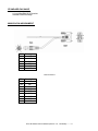
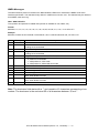
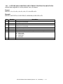
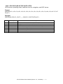
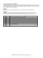
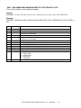
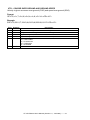
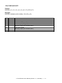
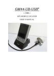
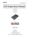
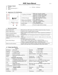
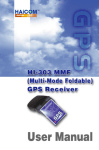
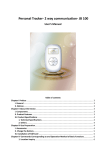
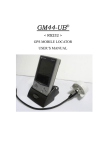
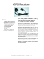
GPS Receiver
UT-41R (DB9 and PS2 cable)
Features
12 parallel channel GPS receiver
4100 simultaneous time-frequency
search bins
SBAS (WAAS, EGNOS) support
-140dBm acquisition sensitivity
-150dBm tracking sensitivity
< 10 second hot start
< 50 second cold start
5m CEP accuracy
PS2 cable
Suitable with the adapter cable
Easy-plug-in Notebook and PC
Fast Acquisition Enhanced Sensitivity
12 Channel GPS Sensor Receiver
The UT-41R is a compact all-in-one GPS module solution
intended for a broad range of Original Equipment
Manufacturer (OEM) products, where fast and easy system
integration and minimal development risk is required.
The receiver continuously tracks all satellites in view and
provides accurate satellite positioning data. The UT-41R is
optimized for applications requiring good performance, low
cost, and maximum flexibility; suitable for a wide range of
OEM configurations including handhelds, sensors, asset
tracking, PDA-centric personal navigation system, and
vehicle navigation products.
Its 12 parallel channels and 4100 search bins provide fast
satellite signal acquisition and short startup time. Acquisition
sensitivity of –140dBm and tracking sensitivity of –150dBm
offers good navigation performance even in urban canyons
having limited sky view.
Satellite-based augmentation systems, such as WAAS and
EGNOS, are supported to yield improved accuracy.
Both the LVTTL-level and RS232-level serial interface are
provided on the interface connector. Supply voltage of
3.8V~8.0V is supported.
UT-41R-RS232 User’s Manual (Version 1.0 , Jun/2006)---------1
TECHNICAL SPECIFICATIONS
Receiver Type
12 parallel channel, L1 C/A code
Accuracy
Position 5m CEP
Velocity 0.1m/sec
Startup Time
< 10sec hot start
< 35sec warm start
< 50sec cold start
Reacquisition
1s
Sensitivity
-140dBm acquisition
-150dBm tracking
Update Rate
1Hz
Dynamics
4G (39.2m/sec )
Operational Limits
Altitude < 18,000m or velocity < 515m/s
(COCOM limit, either may be exceeded but not both)
Serial Interface
LVTTL level and RS-232 level
Protocol
NMEA-0183 V3.01
GPGGA, GPGLL, GPGSA, GPGSV, GPRMC, GPVTG, GPZDA
4800 baud, 8, N, 1 (Default)
Datum
Default WGS-84
User definable
Interface Connector
One 1.0mm pitch WTB S/R wafer 87213 SMT R/A type connector
Input Voltage
3.8V ~ 8.0V
Current Consumption
<100mW
Dimension
34 mm L x 34 mm W x 8.6 mm H
Weight:
14g
Operating Temperature
-40 C ~ +85 C
Humidity
5% ~ 95%
2
o
o
UT-41R-RS232 User’s Manual (Version 1.0 , Jun/2006)---------2
STANDARD PACKAGE
UT-41R Mini-DIN GPS Receiver
Standard OEM Package
MINI-DIN PIN ASSIGNMENT
PS/2 Description
Pin1
N/C
Pin2
N/C
Pin3
GND
Pin4
VCC
Pin5
N/C
Pin6
N/C
* N/C: No Connect
DB9 Description
Pin1
N/C
Pin2
TX
Pin3
RX
Pin4
N/C
Pin5
GND
Pin6
N/C
Pin7
N/C
Pin8
N/C
Pin9
N/C
UT-41R-RS232 User’s Manual (Version 1.0 , Jun/2006)---------3
Customization Package
Color Box
UT-41R-RS232 User’s Manual (Version 1.0 , Jun/2006)---------4
NMEA Messages
The serial interface protocol is based on the National Marine Electronics Association’s NMEA 0183 ASCII
interface specification. This standard is fully define in “NMEA 0183, Version 3.01” The standard may be obtained
from NMEA, www.nmea.org
GGA - GPS FIX DATA
Time, position and position-fix related data (number of satellites in use, HDOP, etc.).
Format:
$GPGGA,<1>,<2>,<3>,<4>,<5>,<6>,<7>,<8>,<9>,M,<10>,M,<11>,<12>,*<13><CR><LF>
Example:
$GPGGA,104549.04,2447.2038,N,12100.4990,E,1,06,01.7,00078.8,M,0016.3,M,,*5C<CR><LF>
Field
1
2
Example
104549.04
2447.2038
3
4
N
12100.4990
5
6
E
1
7
8
9
10
11
06
01.7
00078.8
0016.3
12
13
5C
Description
UTC time in hhmmss.ss format, 000000.00 ~ 235959.99
Latitude in ddmm.mmmm format
Leading zeros transmitted
Latitude hemisphere indicator, ‘N’ = North, ‘S’ = South
Longitude in dddmm.mmmm format
Leading zeros transmitted
Longitude hemisphere indicator, 'E' = East, 'W' = West
Position fix quality indicator
0: position fix unavailable
1: valid position fix, SPS mode
2: valid position fix, differential GPS mode
Number of satellites in use, 00 ~ 12
Horizontal dilution of precision, 00.0 ~ 99.9
Antenna height above/below mean sea level, -9999.9 ~ 17999.9
Geoidal height, -999.9 ~ 9999.9
Age of DGPS data since last valid RTCM transmission in xxx format (seconds)
NULL when DGPS not used
Differential reference station ID, 0000 ~ 1023
NULL when DGPS not used
Checksum
Note: The checksum field starts with a ‘*’ and consists of 2 characters representing a hex
number. The checksum is the exclusive OR of all characters between ‘$’ and ‘*’.
UT-41R-RS232 User’s Manual (Version 1.0 , Jun/2006)---------5
GLL - LATITUDE AND LONGITUDE, WITH TIME OF POSITION FIX AND STATUS
Latitude and longitude of current position, time, and status.
Format:
$GPGLL,<1>,<2>,<3>,<4>,<5>,<6>,<7>*<8><CR><LF>
Example:
$GPGLL,2447.2073,N,12100.5022,E,104548.04,A,A*65<CR><LF>
Field
1
Example
2447.2073
2
3
N
12100.5022
4
5
6
7
E
104548.04
A
A
8
65
Description
Latitude in ddmm.mmmm format
Leading zeros transmitted
Latitude hemisphere indicator, ‘N’ = North, ‘S’ = South
Longitude in dddmm.mmmm format
Leading zeros transmitted
Longitude hemisphere indicator, 'E' = East, 'W' = West
UTC time in hhmmss.ss format, 000000.00 ~ 235959.99
Status, ‘A’ = valid position, ‘V’ = navigation receiver warning
Mode indicator
‘N’ = Data invalid
‘A’ = Autonomous
‘D’ = Differential
‘E’ = Estimated
Checksum
UT-41R-RS232 User’s Manual (Version 1.0 , Jun/2006)---------6
GSA - GPS DOP AND ACTIVE SATELLITES
GPS receiver operating mode, satellites used for navigation, and DOP values.
Format:
$GPGSA,<1>,<2>,<3>,<3>,<3>,<3>,<3>,<3>,<3>,<3>,<3>,<3>,<3>,<3>,<4>,<5>,<6>*<7><C
R><LF>
Example:
$GPGSA,A,3,26,21,,,09,17,,,,,,,10.8,02.1,10.6*07<CR><LF>
Field
1
2
3
4
5
6
7
Example
A
3
26,21,,,09,17,,,,,,
10.8
02.1
10.6
07
Description
Mode, ‘M’ = Manual, ‘A’ = Automatic
Fix type, 1 = not available, 2 = 2D fix, 3 = 3D fix
PRN number, 01 to 32, of satellite used in solution, up to 12 transmitted
Position dilution of precision, 00.0 to 99.9
Horizontal dilution of precision, 00.0 to 99.9
Vertical dilution of precision, 00.0 to 99.9
Checksum
UT-41R-RS232 User’s Manual (Version 1.0 , Jun/2006)---------7
GSV - GPS SATELLITE IN VIEW
Number of satellites in view, PRN number, elevation angle, azimuth angle, and C/No. Only up
to four satellite details are transmitted per message. Additional satellite in view information is
sent in subsequent GSV messages.
Format:
$GPGSV,<1>,<2>,<3>,<4>,<5>,<6>,<7>,…,<4>,<5>,<6>,<7> *<8><CR><LF>
Example:
$GPGSV,2,1,08,26,50,016,40,09,50,173,39,21,43,316,38,17,41,144,42*7C<CR><LF>
$GPGSV,2,2,08,29,38,029,37,10,27,082,32,18,22,309,24,24,09,145,*7B<CR><LF>
Field
1
2
3
4
5
6
7
Example
2
1
08
26
50
016
40
8
7C
Description
Total number of GSV messages to be transmitted
Number of current GSV message
Total number of satellites in view, 00 ~ 12
Satellite PRN number, GPS: 01 ~ 32, SBAS: 33 ~ 64 (33 = PRN120)
Satellite elevation number, 00 ~ 90 degrees
Satellite azimuth angle, 000 ~ 359 degrees
C/No, 00 ~ 99 dB
Null when not tracking
Checksum
UT-41R-RS232 User’s Manual (Version 1.0 , Jun/2006)---------8
RMC - RECOMMANDED MINIMUM SPECIFIC GPS/TRANSIT DATA
Time, date, position, course and speed data.
Format:
$GPRMC,<1>,<2>,<3>,<4>,<5>,<6>,<7>,<8>,<9>,<10>,<11>,<12>*<13><CR><LF>
Example:
$GPRMC,104549.04,A,2447.2038,N,12100.4990,E,016.0,221.0,250304,003.3,W,A*22<CR><
LF>
Field
1
2
3
Example
104549.04
A
2447.2038
4
5
N
12100.4990
6
7
8
9
10
11
12
E
016.0
221.0
250304
003.3
W
A
13
22
Description
UTC time in hhmmss.ss format, 000000.00 ~ 235959.99
Status, ‘V’ = navigation receiver warning, ‘A’ = valid position
Latitude in dddmm.mmmm format
Leading zeros transmitted
Latitude hemisphere indicator, ‘N’ = North, ‘S’ = South
Longitude in dddmm.mmmm format
Leading zeros transmitted
Longitude hemisphere indicator, 'E' = East, 'W' = West
Speed over ground, 000.0 ~ 999.9 knots
Course over ground, 000.0 ~ 359.9 degrees
UTC date of position fix, ddmmyy format
Magnetic variation, 000.0 ~ 180.0 degrees
Magnetic variation direction, ‘E’ = East, ‘W’ = West
Mode indicator
‘N’ = Data invalid
‘A’ = Autonomous
‘D’ = Differential
‘E’ = Estimated
Checksum
UT-41R-RS232 User’s Manual (Version 1.0 , Jun/2006)---------9
VTG - COURSE OVER GROUND AND GROUND SPEED
Velocity is given as course over ground (COG) and speed over ground (SOG).
Format:
GPVTG,<1>,T,<2>,M,<3>,N,<4>,K,<5>*<6><CR><LF>
Example:
$GPVTG,221.0,T,224.3,M,016.0,N,0029.6,K,A*1F<CR><LF>
Field
1
2
3
4
5
Example
221.0
224.3
016.0
0029.6
A
6
1F
Description
True course over ground, 000.0 ~ 359.9 degrees
Magnetic course over ground, 000.0 ~ 359.9 degrees
Speed over ground, 000.0 ~ 999.9 knots
Speed over ground, 0000.0 ~ 1800.0 kilometers per hour
Mode indicator
‘N’ = Data invalid
‘A’ = Autonomous
‘D’ = Differential
‘E’ = Estimated
Checksum
UT-41R-RS232 User’s Manual (Version 1.0 , Jun/2006)---------10
ZDA TIME AND DATE
Format:
$GPZDA,<1>,<2>,<3>,<4>,<5>,<6>*<7><CR><LF>
Example:
$GPZDA,104548.04,25,03,2004,,*6C<CR><LF>
Field
1
2
3
4
5
Example
104548.04
25
03
2004
6
7
6C
Description
UTC time in hhmmss.ss format, 000000.00 ~ 235959.99
UTC time: day (01 ... 31)
UTC time: month (01 ... 12)
UTC time: year (4 digit year)
Local zone hour
Not being output by the receiver (NULL)
Local zone minutes
Not being output by the receiver (NULL)
Checksum
UT-41R-RS232 User’s Manual (Version 1.0 , Jun/2006)---------11