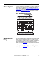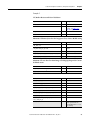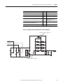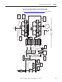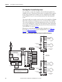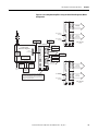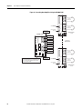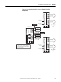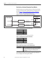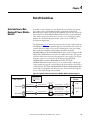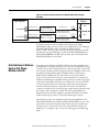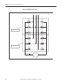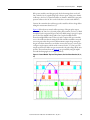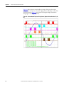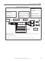
1
User Manual
PowerFlex DC Stand Alone Regulator and Gate
Amplifier
Important User Information
Solid-state equipment has operational characteristics differing from those of electromechanical equipment. Safety
Guidelines for the Application, Installation and Maintenance of Solid State Controls (publication SGI-1.1 available from
your local Rockwell Automation sales office or online at http://www.rockwellautomation.com/literature/) describes some
important differences between solid-state equipment and hard-wired electromechanical devices. Because of this difference,
and also because of the wide variety of uses for solid-state equipment, all persons responsible for applying this equipment
must satisfy themselves that each intended application of this equipment is acceptable.
In no event will Rockwell Automation, Inc. be responsible or liable for indirect or consequential damages resulting from
the use or application of this equipment.
The examples and diagrams in this manual are included solely for illustrative purposes. Because of the many variables and
requirements associated with any particular installation, Rockwell Automation, Inc. cannot assume responsibility or
liability for actual use based on the examples and diagrams.
No patent liability is assumed by Rockwell Automation, Inc. with respect to use of information, circuits, equipment, or
software described in this manual.
Reproduction of the contents of this manual, in whole or in part, without written permission of Rockwell Automation,
Inc., is prohibited.
Throughout this manual, when necessary, we use notes to make you aware of safety considerations.
WARNING: Identifies information about practices or circumstances that can cause an explosion in a hazardous
environment, which may lead to personal injury or death, property damage, or economic loss.
ATTENTION: Identifies information about practices or circumstances that can lead to personal injury or death,
property damage, or economic loss. Attentions help you identify a hazard, avoid a hazard, and recognize the
consequence
SHOCK HAZARD: Labels may be on or inside the equipment, for example, a drive or motor, to alert people that
dangerous voltage may be present.
BURN HAZARD: Labels may be on or inside the equipment, for example, a drive or motor, to alert people that
surfaces may reach dangerous temperatures.
IMPORTANT
Identifies information that is critical for successful application and understanding of the product.
Allen-Bradley, PowerFlex, Rockwell Software, Rockwell Automation, and TechConnect are trademarks of Rockwell Automation, Inc.
Trademarks not belonging to Rockwell Automation are property of their respective companies.
Summary of Changes
This manual contains new and updated information.
Topic
Page
Removed the reference to the S12 / S12R configuration from the Features list.
12
Rockwell Automation Publication 23P-UM001D-EN-P - July 2012
3
Summary of Changes
4
Rockwell Automation Publication 23P-UM001D-EN-P - July 2012
Table of Contents
Preface
Purpose of This Manual . . . . . . . . . . . . . . . . . . . . . . . . . . . . . . . . . . . . . . . . . . . . 7
What This Manual Contains. . . . . . . . . . . . . . . . . . . . . . . . . . . . . . . . . . . . . . . . 7
Drawing Numbers . . . . . . . . . . . . . . . . . . . . . . . . . . . . . . . . . . . . . . . . . . . . . . . . . 7
Additional Resources . . . . . . . . . . . . . . . . . . . . . . . . . . . . . . . . . . . . . . . . . . . . . . . 7
Chapter 1
Introduction
General Precautions . . . . . . . . . . . . . . . . . . . . . . . . . . . . . . . . . . . . . . . . . . . . . . . . 9
Product Overview . . . . . . . . . . . . . . . . . . . . . . . . . . . . . . . . . . . . . . . . . . . . . . . . 10
Stand Alone Regulator. . . . . . . . . . . . . . . . . . . . . . . . . . . . . . . . . . . . . . . . . . . . 12
Gate Amplifier . . . . . . . . . . . . . . . . . . . . . . . . . . . . . . . . . . . . . . . . . . . . . . . . . . . 12
Chapter 2
Stand Alone Regulator
Installation, Wiring and
Configuration
Prepare for Installation . . . . . . . . . . . . . . . . . . . . . . . . . . . . . . . . . . . . . . . . . . .
Mounting Considerations . . . . . . . . . . . . . . . . . . . . . . . . . . . . . . . . . . . . . . . .
CE Conformity . . . . . . . . . . . . . . . . . . . . . . . . . . . . . . . . . . . . . . . . . . . . . . . . . .
Terminal/Signal and Wiring Diagrams. . . . . . . . . . . . . . . . . . . . . . . . . . . . .
Field Power Module Bridge and Ground Wiring . . . . . . . . . . . . . . . . . . . .
AC/DC Voltage and Motor Armature Voltage Feedback Wiring . . . .
Power Module Thermal Switch and Current Transformer Wiring . . .
SAR Gate Output Cable . . . . . . . . . . . . . . . . . . . . . . . . . . . . . . . . . . . . . . . . . .
Control Circuit Power Wiring . . . . . . . . . . . . . . . . . . . . . . . . . . . . . . . . . . . .
SAR Motor Field Current Configuration . . . . . . . . . . . . . . . . . . . . . . . . . .
SAR Sizing . . . . . . . . . . . . . . . . . . . . . . . . . . . . . . . . . . . . . . . . . . . . . . . . . . . . . .
SAR Current Feedback Configuration . . . . . . . . . . . . . . . . . . . . . . . . . . . . .
SAR Programming and Startup. . . . . . . . . . . . . . . . . . . . . . . . . . . . . . . . . . . .
Gate Amplifier Installation and
Wiring
Retrofit Guidelines
13
13
16
18
20
21
24
25
25
26
27
28
40
Chapter 3
Prepare for Installation . . . . . . . . . . . . . . . . . . . . . . . . . . . . . . . . . . . . . . . . . . .
Operating Temperatures. . . . . . . . . . . . . . . . . . . . . . . . . . . . . . . . . . . . . . . . . .
Mounting and Cooling . . . . . . . . . . . . . . . . . . . . . . . . . . . . . . . . . . . . . . . . . . .
Power and Ground Wiring. . . . . . . . . . . . . . . . . . . . . . . . . . . . . . . . . . . . . . . .
Chassis Grounding . . . . . . . . . . . . . . . . . . . . . . . . . . . . . . . . . . . . . . . . . . . . . . .
Control Wiring Connections . . . . . . . . . . . . . . . . . . . . . . . . . . . . . . . . . . . . .
41
41
42
44
45
48
Chapter 4
Gate Interface to Non-Rockwell Power Module, Retrofit . . . . . . . . . . . . 59
Gate Interface to Reliance Electric U.S. Power Modules, Retrofit. . . . . 61
Gate Interface to Dierikon Power Modules . . . . . . . . . . . . . . . . . . . . . . . . . 64
Chapter 5
Power Interface and SCR Firing Parallel Power Modules and Load Share Reactors . . . . . . . . . . . . . . . . . . . 65
Phase Sequence and Armature SCR Firing Order . . . . . . . . . . . . . . . . . . . 65
Order
Rockwell Automation Publication 23P-UM001D-EN-P - July 2012
5
Table of Contents
Specifications
History of Changes
Index
6
Appendix A
Stand Alone Regulator . . . . . . . . . . . . . . . . . . . . . . . . . . . . . . . . . . . . . . . . . . . .
Gate Amplifier . . . . . . . . . . . . . . . . . . . . . . . . . . . . . . . . . . . . . . . . . . . . . . . . . . .
Gate Coupler Assembly Information . . . . . . . . . . . . . . . . . . . . . . . . . . . . . . .
Gate Scaling Module Information. . . . . . . . . . . . . . . . . . . . . . . . . . . . . . . . . .
Cable Specifications . . . . . . . . . . . . . . . . . . . . . . . . . . . . . . . . . . . . . . . . . . . . . .
71
71
73
76
78
Appendix B
23P-UM001C-EN-P, September, 2011 . . . . . . . . . . . . . . . . . . . . . . . . . . . . 83
23P-UM001B-EN-P,
April 2011 . . . . . . . . . . . . . . . . . . . . . . . . . . . . . . . . . . . . . . . . . . . . . . . . . . . . . . . 83
. . . . . . . . . . . . . . . . . . . . . . . . . . . . . . . . . . . . . . . . . . . . . . . . . . . . . . . . . . . . . . . . . 85
Rockwell Automation Publication 23P-UM001D-EN-P - July 2012
Preface
Purpose of This Manual
This manual provides installation instructions and connection and configuration
information for the PowerFlex® DC Stand Alone Regulator (SAR) and the Gate
Amplifier. It is intended for internal Rockwell Automation use only.
What This Manual Contains
This user manual contains the following sections:
• Description of the SAR and Gate Amplifier products and general
integration information
• Installation, connection and configuration instructions for the SAR
• Installation and connection instructions for the Gate Amplifier
• Guidelines for retrofit installations with DC power modules
• SAR and Gate Amplifier specifications
• Specifications for additional components and cables used with the SAR
and Gate Amplifier products
Drawing Numbers
Throughout this manual, drawings are identified by an eight-digit number, for
example, 99999999. Where a drawing number includes an asterisk (*) in the 8th
digit, the “*” represents the latest version number of the drawing, for example,
999999*.
Additional Resources
These documents contain additional information concerning the PowerFlex DC
Stand Alone Regulator and related Rockwell Automation products.
Resource
Description
PowerFlex Digital DC Drive User Manual,
publication 20D-UM001
Provides additional installation, configuration,
and programming information for the Stand
Alone Regulator.
Industrial Automation Wiring and Grounding
Guidelines, publication 1770-4.1
Provides general guidelines for installing a
Rockwell Automation industrial system.
Product Certifications website, http://ab.com
Provides declarations of conformity, certificates,
and other certification details.
You can view or download publications at http://www.rockwellautomation.com/
literature/. To order paper copies of technical documentation, contact your local
Rockwell Automation distributor or sales representative.
Rockwell Automation Publication 23P-UM001D-EN-P - July 2012
7
preface
Notes:
8
Rockwell Automation Publication 23P-UM001D-EN-P - July 2012
Chapter
1
Introduction
General Precautions
Prior to installation of either the Stand Alone Regulator or Gate Amplifier, read
the following precautions.
ATTENTION: Energized industrial control equipment can be hazardous.
Severe injury or death can result from electrical shock, burn, or unintended
actuation of controlled equipment. Hazardous voltages may exist in the
cabinet even with the circuit breaker in the off position. Recommended
practice is to disconnect and lock out control equipment from power
sources, and discharge stored energy in capacitors, if present. If it is
necessary to work in the vicinity of energized equipment, the Safety
Related Practices of NFPA 70E, “ELECTRICAL SAFETY FOR EMPLOYEE
WORKPLACES” must be followed. DO NOT work alone on energized
equipment!
ATTENTION: The following information is merely a guide for proper
installation. The National Electrical Code and any other governing regional
or local code will overrule this information. Rockwell Automation cannot
assume responsibility for the compliance or the noncompliance to any
code, national, local or otherwise for the proper installation of this drive
regulator or associated equipment. A hazard of personal injury and/or
equipment damage exists if codes are ignored during installation.
ATTENTION: The installation of the Stand Alone Regulator and/or the
Gate Amplifier must be planned such that all cutting, drilling, tapping and
welding can be accomplished with the Gate Amplifier removed from the
enclosure. The Stand Alone Regulator and Gate Amplifier are of the open
type construction and any metal debris must be kept from falling into the
enclosure. Metal debris or other foreign matter may become lodged in the
circuitry resulting in component damage.
ATTENTION: An incorrectly applied or installed Stand Alone Regulator or
Gate Amplifier can result in component damage or a reduction in product
life. Wiring or application errors, such as, incorrect or inadequate supply
voltage or excessive ambient temperatures may result in malfunction of
the system.
ATTENTION: Only qualified personnel familiar with DC drives and
associated machinery should plan or implement the installation, start-up
and subsequent maintenance of the system. Failure to comply may result
in personal injury and/or equipment damage.
ATTENTION: The Stand Alone Regulator and Gate Amplifier contain ESD
(Electrostatic Discharge) sensitive parts and assemblies. Static control
precautions are required when installing, testing, servicing or repairing
this assembly. Component damage may result if ESD control procedures
are not followed. If you are not familiar with static control procedures,
reference A-B publication 8000-4.5.2, “Guarding Against Electrostatic
Damage” or any other applicable ESD protection handbook.
Rockwell Automation Publication 23P-UM001D-EN-P - July 2012
9
Chapter 1
Introduction
Product Overview
The PowerFlex DC Stand Alone Regulator (SAR) and Gate Amplifier products
provide an integrated solution for controlling external DC power modules.
Stand Alone Regulator (SAR)
The SAR is a DC drive regulator that provides armature regulation, armature
SCR gate signals and a regulated field supply. The SAR field supply consists of a
single phase, two quadrant (non-reversing,) full wave rectified bridge, available as
40 or 70 Amps. The SAR supports an AC line input voltage range of 230VAC to
690VAC and a field input voltage range of 100VAC to 460VAC.
The SAR uses feedback signals from the AC input line to monitor the incoming
voltage level in order to establish the SCR gate firing sequence relative to the AC
line. The SCR gate firing for the field bridge is established from the AC lines that
supply the field, independent of the armature firing circuit. DC feedback signals
are used to monitor the output voltage from the power module. Additionally,
current signals received from current transformers is used by the SAR regulator to
monitor and control current. The SAR catalog numbers are listed in Catalog
Numbers on page 12. The SAR must be used with the Gate Amplifier in order to
interface with a DC power module(s).
Gate Amplifier
The Gate Amplifier is used to amplify the SCR gate signals supplied by a DC
drive regulator. The gate signal source to the Gate Amplifier can be provided by
either the PowerFlex DC SAR, or the SD3000 PLUS. The Gate Amplifier unit
provides a separate input D-Shell connector for each product. The Power
Module Interface (PMI) Rack is also compatible with the Gate Amplifier and
uses the SD3000 PLUS inputs. The Gate Amplifier model number and
corresponding connection cables part numbers are listed in Model and Cable
Model/Part Numbers on page 12.
In addition to amplifying the gate signals, the forward and reverse signals
provided by the Gate Amplifier are “fanned-out” to enable the driving of multiple
power modules. Four S6 bridges forward and four S6 bridges reverse. When the
S6 bridges are connected in an anti-parallel configuration, the topology is an S6R
providing both motoring and regenerative capability.
The external 48V gate power supply capability of the Gate Amplifier provides the
means to supply additional gate current and voltage and also support the firing of
gate coupler boards connected in series (which requires additional voltage).
Connecting gate couplers in series forces the simultaneous firing of the SCRs,
with power connections in series or parallel. An internal “diode OR” circuit
ensures that the gates are powered by whichever gate power supply voltage is the
greater in amplitude, the internal or the external power supply.
10
Rockwell Automation Publication 23P-UM001D-EN-P - July 2012
Rockwell Automation Publication 23P-UM001D-EN-P - July 2012
To Motor
Field
C1 D1
Power Module
AC / DC
Feedback
DCWVU
KP
Power Module
Armature Voltage
Feedback
1A1 A1 1A2 A2
KA
All Terminals are located
on the bottom of the unit.
Power Module
Thermostat and
CT Feedback
12345678
KPT31
KPT11
(15 Pin D-Shell)
PowerFlex DC
Stand Alone Regulator
Field Supply
40 A or 70 A
(2 Quad)
V1 U1
Normally
Open Contacts
to Stop Circuitry
Gate Cable
RDY
+
-
Ext. P/S
120VAC
REV
FWD
48V Ext P/S
(If Required)
SD3K
REV IN
SD3K
FWD IN
PFDC
Gate Input
Gate Amplifier
P/S
MONITOR
RELAY
To Stop
Circuitry
Motor Field
FWD
1
To Encoder or Resolver
Feedback Port
From Stand-Alone
Regulator
GATE COUPLER
ASSEMBLY
GATE COUPLER
ASSEMBLY
L1, L2, L3
AC
CT FDBK to PFDC SAR
Motor
CTs on
L1 and L3
+DC and -DC
Power Module
Output
REV
1
Encoder or Resolver Feedback
M
AC
Input
Introduction
Chapter 1
Figure 1 - Typical PowerFlex DC Stand Alone Regulator and Gate Amplifier
Interface to S6R
11
Chapter 1
Introduction
Stand Alone Regulator
Features
•
Rockwell Automation Architecture Class networking capable
Available Options
•
Resolver Feedback
Catalog Numbers
This table lists the available catalog numbers for the SAR.
230V / 460V AC Input
Catalog Number
23PMD4
23PMD7
575V / 690V AC Input
Catalog Number:
23PMF4
23PMF7
Field Amps
40
70
Note: All models contain conformal coated circuit boards.
Gate Amplifier
Features
•
•
•
•
Interfaces to the PowerFlex DC, SD3000 PLUS or PMI regulators
Flexible configurations S6 and S6R
Power module interface
Interlock via “Ready Relay” contacts to main drive control
Available Options
•
48V gate drive capability with an external power supply
Model and Cable Model/Part Numbers
This table lists the cable module numbers and part numbers for the Gate
Amplifier.
Product:
Gate Amplifier
PowerFlex DC to Gate Amplifier Cable
SD3000 PLUS to Gate Amplifier Forward Cable
SD3000 PLUS to Gate Amplifier Reverse Cable
PMI Rack to Gate Amplifier Forward Cable
PMI Rack to Gate Amplifier Reverse Cable
Model/Part Number:
23PAMP
See Cable Specifications on page 78.
SD3K-CBLGSCLIFxxx(1)
SD3K-CBLGSCLIRxxx(1)
612432-xxxS(1)
612433-xxxS(1)
(1) xxx = length in inches.
12
Rockwell Automation Publication 23P-UM001D-EN-P - July 2012
Chapter
2
Stand Alone Regulator Installation, Wiring
and Configuration
Prepare for Installation
Prior to installation of the PowerFlex DC Stand Alone Regulator (SAR) read the
General Precautions on page 9.
Mounting Considerations
Operating Conditions and Temperatures
The SAR is designed to operate at 0°…50° C (32°… 122° F) surrounding air
temperature without derating. The unit must be mounted in a clean, dry location.
Contaminants such as oils, corrosive vapors and abrasive debris must be kept out
of the enclosure. NEMA/UL Type Open, IP20 enclosures are intended for
indoor use primarily to provide a degree of protection against contact with
enclosed equipment. These enclosures offer no protection against airborne
contaminants.
Rockwell Automation Publication 23P-UM001D-EN-P - July 2012
13
Chapter 2
Stand Alone Regulator Installation, Wiring and Configuration
Minimum Mounting Clearances
Minimum clearance requirements (indicated in Figure 2 - Drive Enclosure
Minimum Mounting Clearances) are intended to be from enclosure to enclosure.
Other objects can occupy this space; however, reduced airflow may cause
protection circuits to fault the SAR. The SAR must be mounted in a vertical
orientation as shown and must not be mounted at an angle greater than 30
degrees from vertical. In addition, inlet air temperature must not exceed the
product specification.
Figure 2 - Drive Enclosure Minimum Mounting Clearances
Min. 150 mm
(6.0 in.)
Min. 10 0 mm
(0.4 in.)
14
Min. 150 mm
(6.0 in.)
Min. 150 mm
(6.0 in.)
Min. 10 0 mm
(0.4 in.)
Min. 150 mm
(6.0 in.)
Min. 50 mm
(2.0 in.)
Min. 10 0 mm
(0.4 in.)
Rockwell Automation Publication 23P-UM001D-EN-P - July 2012
Airflow through the unit
must not be impeded.
Stand Alone Regulator Installation, Wiring and Configuration
Chapter 2
Approximate Dimensions and Weights
The SAR is available in a NEMA/UL Type Open, IP20 enclosure only.
ATTENTION: Remove all loose packaging materials, including any
desiccant packages from the enclosure before mounting and energizing
the SAR.
Dimensions are shown in mm (in.)
8.4 (0.33)
23.3
(0.92)
250.0 (9.84)
285.4 (11.24)
19.5
(0.77)
275.0
(10.83)
397.9
(15.67)
341.0
(13.43)
266.8
(10.51)
Table 1 - Stand Alone Regulator Weights
Stand Alone Regulator
Stand Alone Regulator and Packaging
12.0 kg (26.5 lb)
14.1 kg (31 lb)
Recommended Mounting Hardware: Metric M6, English 1/4 in.
IMPORTANT
Provide a minimum of 150 mm (6.0 in.) below the unit for cable
connections.
Rockwell Automation Publication 23P-UM001D-EN-P - July 2012
15
Chapter 2
Stand Alone Regulator Installation, Wiring and Configuration
CE Conformity
Conformity with the Low Voltage Directive and Electromagnetic Compatibility
Directive has been demonstrated using harmonized European Norm (EN)
standards published in the Official Journal of the European Communities. The
PowerFlex DC Stand Alone Regulator complies with the EN standards listed
when installed according to this User Manual.
CE Declarations of Conformity are available online at:
www.rockwellautomation.com/products/certification/ce/
Low Voltage Directive (2006/95/EC)
• EN 50178 Electronic equipment for use in power installations.
EMC Directive (2004/108/EC)
• EN 61800-3 Adjustable speed electrical power drive systems Part 3: EMC
product standard including specific test methods.
General Considerations
• For CE compliance, the SAR installation must satisfy requirements related
to both EN 50178 and EN 61800-3 provided in this document.
• The SAR complies with the EMC requirements of EN 61800-3 when
installed according to good EMC practices and the instructions provided
in this document. However, many factors can influence the EMC
compliance of an entire machine or installation, and compliance of the
SAR itself does not necessarily ensure compliance of all applications.
• The SAR is not intended to be used on public supply networks which
supply domestic premises. Without additional mitigation, radio frequency
interference is expected if used on such a network. The installer is
responsible to take measures such as supplementary line filters and
enclosures to prevent interference, in addition to the installation
requirements of this document.
Installation Requirements Related to EN 50178 and the Low
Voltage Directive
• The SAR is compliant with the CE LV Directive when used at altitudes no
greater than 2000 m (6562 ft).
• The SAR provided in enclosure type IP20 must be installed in a pollution
degree 1 or 2 environment to be compliant with the CE LV Directive.
Characteristics of the different pollution degree ratings are provided in
Table 2 on page 17.
16
Rockwell Automation Publication 23P-UM001D-EN-P - July 2012
Stand Alone Regulator Installation, Wiring and Configuration
Chapter 2
Table 2 - Pollution Degree Ratings According to EN 61800-5-1
Pollution Degree
Description
1
No pollution or only dry, non-conductive pollution occurs. The pollution has no
influence.
2
Normally, only non-conductive pollution occurs. Occasionally, however, a
temporary conductivity caused by condensation is to be expected, when the
drive is out of operation.
3
Conductive pollution or dry non-conductive pollution occurs, which becomes
conductive due to condensation, which is to be expected.
4
The pollution generates persistent conductivity caused, for example by
conductive dust or rain or snow.
• The SAR must be installed in a suitable enclosure with at least an IP4X
rating at the top of the enclosure.
• The SAR may produce leakage current in the protective earthing
conductor which exceeds 3.5 mA AC and/or 10 mA DC. The minimum
size of the protective earthing (grounding) conductor used in the
application must comply with local safety regulations for equipment with
high protective earthing conductor current.
• The SAR may not be powered from a “corner-earthed” supply system in
order to maintain compliance with the CE LV Directive.
Installation Requirements Related to EN 61800-3 and the EMC
Directive
• The SAR must be earthed (grounded) as described in this User Manual.
• Output power wiring to the motor (field excitation) must employ cable
with a braided shield providing 75% or greater coverage, or the cable must
be housed in metal conduit, or equivalent shielding must be provided.
Continuous shielding must be provided from the SAR enclosure to the
motor enclosure. Both ends of the motor cable shield (or conduit) must
terminate with a low-impedance connection to earth.
• At the motor end, the motor field excitation cable shield or conduit must
terminate in a shielded connector which must be properly installed in an
earthed motor wiring box attached to the motor. The motor wiring box
cover must be installed and earthed.
• All control (I/O) and signal wiring to the SAR, including gate firing
control, must use cable with a braided or foil shield providing 75% or
greater coverage, or the cables must be housed in metal conduit, or
equivalent shielding must be provided. Only the SAR end of the cable
shield should be terminated with a low impedance connection to earth.
• Power cabling must be separated from control and signal wiring wherever
possible.
Rockwell Automation Publication 23P-UM001D-EN-P - July 2012
17
Chapter 2
Stand Alone Regulator Installation, Wiring and Configuration
Terminal/Signal and Wiring
Diagrams
Use the diagram in Figure 3 - Stand Alone Regulator Terminal/Signal Block
Diagram as a guide for the general location of and connection signals for the main
input/output terminal blocks on the SAR. The diagram in Figure 4 on page 19
represents the recommended wiring for a typical SAR interface to a S6R power
module.
Figure 3 - Stand Alone Regulator Terminal/Signal Block Diagram
Bottom View
V , A C _In
Gate Output
U , A C _ In
C , “+ ”
D , “-”
W, A C _ In
AC / DC Feedback
Front of Unit
Connector
“KP”
Connector
“KPT11”
(P M O ut + “C ”)
M otor A r m F dbk “+ ”
( P M O ut - “D ”)
Mo to r A rm F d bk “-”
Power Module Armature Feedback
1 A1
A1
1 A2
A2
Connector
“KA”
18
Rockwell Automation Publication 23P-UM001D-EN-P - July 2012
3
4
5
C T2 -
C T1 +
2
C T1 -
( No t_U se d )
1
C T2 +
T h e rm _C o m
Connector
“KPT31”
IS O _C o m
PE (GND)
+ V _th e rm , + 1 5 V
Power Module Thermal / CT Feedback
D 1 , D C _ O u t “- ”
V 1 , A C _In
U 1 , A C _In
C 1, D C _O u t “+”
Field Bridge, AC Input / DC Ouput
6
7
8
U1
V1
V
D1
Rockwell Automation Publication 23P-UM001D-EN-P - July 2012
Armature
Voltage
Feedback
Armature
Current
Feedback
Motor Field
C1
+
Field PM Therm
Field Regulator (2 Quad)
See page 21 for
Fuse Sizes
(External to SAR)
Transformer
(External to SAR)
U
From Incoming AC Line
J4
Ext.
Rb
XCT
#S2
(Test
Pt.)
CT2 -
CT2 +
CT1 -
CT1 +
8
7
6
5
4
3
2
1
(PM Out + “C”) 1A1
Pwr Mod / Arm Fdbk
Conn “KA”
D, “-”
C, “+”
W, AC_In
V, AC_In
U, AC_In
AC / DC Feedback
Conn “KP”
0V ISO
(Not_Used)
Therm_Com
ISO_Com
+V_Therm, +15V
Gate Output
Conn “KPT11”
Motor Arm Fdbk “-” A2
(PM Out - “D”) 1A2
Motor Arm Fdbk “+” A1
Internal Fuses
2.5
Ohms
2.5
Ohms
OT
To Voltage
Feedback
Circuits
J5
+15 V ISO
Pwr Mod Thermal / CT Feedback
Conn “KPT31”
Stand Alone Regulator (SAR)
V
(L2)
W
(L3)
“+”
C
U
U
(L1)
M
V
V
(L2)
Fault
W
M
“-”
D
Gate Input
Warning
CT2
W
(L3)
Supplied by SAR
Field Power Module
(or separately excited)
Motor Field
M
CT1
5A, 700V
5A, 700V
To Gate Amplifier
(refer to gate wiring
diagrams)
*(See
Note)
*(See
Note)
U
(L1)
From AC Line Above
Therm
Fault
On Pwr Mod
To Field Power
Module
Transformer
Incoming AC Line
From Gate
Amplifier Output
(refer to gate
wiring diagrams)
Gates
To Digital I/O
(if available)
To SAR
Conn “KPT31”
To SAR
Conn “KP”
* Note: Armature Voltage
Feedback. Jumpers
must always be in place.
W, (L3)
V, (L2)
U, (L1)
Stand Alone Regulator Installation, Wiring and Configuration
Chapter 2
Figure 4 - Typical Stand Alone Regulator Interface to S6R Power Module
19
Chapter 2
Stand Alone Regulator Installation, Wiring and Configuration
Field Power Module Bridge
and Ground Wiring
The SAR contains a two quadrant field power module bridge. The field bridge
input circuit is rated for 100VAC…460VAC, ±10%, 50/60 Hz. The input and
output connections to/from the field bridge are on the bottom of the SAR as
shown.
An external transformer with appropriate primary fusing is required to supply the
field. External fusing is also required at the input terminals V1 and U1 to protect
the field bridge. The recommended fuse types are shown in the Table 4 on
page 21.
The SAR motor field current must configured with a hardware DIP switch and in
firmware. See SAR Motor Field Current Configuration on page 26 for more
information.
Figure 5 - Field Power Module Bridge Terminal Block and Ground Connection
Bottom View of SAR
KPT21
1 Field Power
Module Bridge
Terminal Block
KPT11
D C W V U
V1
U1
C1
D1
KPT31
1 2 3 4 5 6 7 8
2 PE Terminal
PE
1A1 (C)A1 1A2 (D)A2
Table 3 - Field Power Module Bridge and Ground Terminal Specifications
No. Terminal
V1, U1
1
C1, D1
1
2
PE
Description
AC Input Power
Wire Size Range
Maximum
Minimum
25.0 mm2
DC Output Power (2 AWG)
to Motor Field
Safety Ground (1) 16.0 mm2
(6 AWG)
(1) See Safety Ground (PE) on page 21 for more information.
20
Rockwell Automation Publication 23P-UM001D-EN-P - July 2012
Recommended
Torque
10.0 mm2
(10 AWG)
4.0…4.5 N•m
(35.4…39.8 lb•in)
10.0 mm2
(8 AWG)
6.0…8.0 N•m
(53.1…70.8 lb•in)
Stand Alone Regulator Installation, Wiring and Configuration
Chapter 2
Table 4 - Recommended Field Power Module Bridge Input Fuses
Fuse Type:
SAR Field
Bridge Rating
Bussmann
Ferraz Shawmut
Siba
40 A
FWP-50A22Fa
A70QS50-22F
5014006.50
70 A
FWP-100A22Fa
A70QS100-22F
5014006.100
The recommended fuse holder is a Cooper-Bussman, CH222D or equivalent - to
accommodate 22 mm x 58 mm fuses.
Safety Ground (PE)
The Safety Ground - PE must be connected to system ground. Ground
impedance must conform to the requirements of national and local industrial
safety regulations and/or electrical codes. The integrity of all ground connections
should be periodically checked.
For installations within a cabinet, a single safety ground point or ground bus bar
connected directly to building steel should be used. All circuits should be
grounded independently and directly to this point/bar.
AC/DC Voltage and Motor
Armature Voltage Feedback
Wiring
The SAR requires AC feedback connections to connector KP (terminals U, V,
and W) from the incoming line to monitor the incoming voltage level and
establish the SCR gate firing sequence relative to the AC line. DC feedback
connections to connector KP (terminals C and D) are required to monitor the
voltage output from the DC power module. The combined information from the
AC and DC feedback inputs is used to determine if the SCRs are firing properly.
See Figure 4 on page 19 for recommended wiring for a typical SAR interface to
S6R.
Fuses are required between the DC output power wiring on the DC power
module to connector KP on the SAR. This will limit the current to the regulator
in the event of an internal fault in the SAR. The recommended fuse types are
shown in DC Feedback Fusing Requirements on page 22.
Rockwell Automation Publication 23P-UM001D-EN-P - July 2012
21
Chapter 2
Stand Alone Regulator Installation, Wiring and Configuration
Figure 6 - AC /DC Voltage Feedback (KP) and Motor Armature Voltage Feedback
(KA) Terminal Blocks
Bottom View of SAR
KPT21
KPT11
D C W V U
1 AC /DC Voltage
Feedback (KP)
Terminal Block
V1
U1
C1
D1
KPT31
1 2 3 4 5 6 7 8
PE
1A1 (C)A1 1A2 (D)A2
2 Motor Armature
Voltage Feedback
(KA) Terminal
Block
Table 5 - AC / DC Voltage and Motor Armature Voltage Feedback Terminal
Specifications
No. Terminal
W, V, U
1
1
D, C
1A1, A1,
2 1A2, A2
Wire Size Range
Description
Maximum
Minimum
AC Input
Feedback
(connector KP)
DC Output
6.0 mm2
0.2 mm2
Feedback
(10
AWG)
(24 AWG)
(connector KP)
Motor Armature
Voltage Feedback
(connector KA)
Recommended
Torque
0.7…0.8 N•m
(6.2…7.1 lb•in)
DC Feedback Fusing Requirements
The recommended fuses are:
• Bussmann fuse FWP-5A14F (5 A, 700V, Type FWP, 14 x 51mm), or
equivalent.
Note: The AC voltage feedback inputs on the SAR are fused internally.
22
Rockwell Automation Publication 23P-UM001D-EN-P - July 2012
Stand Alone Regulator Installation, Wiring and Configuration
Chapter 2
Connector KP Wiring
• Connect the motor armature terminal C to terminal C on connector KP
• Connect the motor armature terminal D to terminal D on connector KP
Connector KA Wiring
Connector KA must be wired to provide DC voltage feedback to the field
regulator to control the field current based on the armature voltage. Terminal
1A1 is connected internally to terminal C (on connector KP) and terminal 1A2
is connected internally to terminal D (on connector KP). The default
configuration is shown in Figure 7 and is wired as follows:
• Jumper terminal 1A1 to terminal A1
• Jumper terminal 1A2 to terminal A2
The jumpers will provide the field regulator with the power module/armature
voltage feedback. This is the default wiring scheme for connector KA at the
factory.
Figure 7 - Terminals on Connector KA Jumpered
1A1(C) A1 1A2 (D) A2
Place jumpers between
terminals as shown
Rockwell Automation Publication 23P-UM001D-EN-P - July 2012
23
Chapter 2
Stand Alone Regulator Installation, Wiring and Configuration
Power Module Thermal
Switch and Current
Transformer Wiring
Connector KPT31 is used for power module thermal switch monitoring and
current feedback via current transformer connections. Note that the thermal
monitor circuit includes a thermal switch on the field power module within the
SAR.
Figure 8 - Power Module Thermal Switch and Current Transformer Terminal Block
(KPT31)
Bottom View of SAR
KPT21
KPT11
D C W V U
V1
U1
C1
D1
KPT31
1 2 3 4 5 6 7 8
Power Module
Thermal Switch and
Current Transformer
(KPT31) Terminal
Block
PE
1A1 (C)A1 1A2 (D)A2
Table 6 - Power Module Thermal Switch and Current Transformer Terminal
Specifications
Terminal
1, 2, 3
5, 6, 7, 8
Description
Thermal Switch Monitor(1)
Current Transformer Feedback
Wire Size Range
Maximum
Minimum
2.5 mm2
0.2 mm2
(12 AWG)
(24 AWG)
Recommended
Torque
0.5…0.6 N•m
(4.4…5.3 lb•in)
(1) These terminals are jumpered by default. The jumper wires must remain in place if a power module thermal
switch is NOT connected.
Current Transformer Connections
Current transformer 1 (CT1) monitors the U phase, with the “+” output of CT1
connected to terminal 5 of KPT31 and the “-” output of CT1 connected to
terminal 6 of KPT31.
Current transformer 2 (CT2) monitors the W phase, with the “+” output of
CT2 connected to terminal 7 of KPT31 and the “-” output of CT2 connected to
terminal 8 of KPT31.
The “-” side of the CTs are connected together internally in the SAR.
24
Rockwell Automation Publication 23P-UM001D-EN-P - July 2012
Stand Alone Regulator Installation, Wiring and Configuration
SAR Gate Output Cable
Chapter 2
Connect the SAR gate output cable (23PAMP-Cx) to connector KPT11 on the
SAR unit. The opposite end connects to the POWERFLEX DC SAR GATE
INPUT on the Gate Amplifier. See Chapter 3 Gate Amplifier Installation and
Wiring on page 41 for more information on Gate Amplifier installation and
connections. See Cable Specifications on page 78 for information on available
cable lengths for the 23PAMP-Cx cable.
Figure 9 - SAR Gate Output Cable Connection (KPT11)
Bottom View of SAR
KPT21
KPT11
D C W V U
V1
U1
C1
D1
KPT31
1 2 3 4 5 6 7 8
SAR Gate Output
Cable (KPT11)
Connector
PE
1A1 (C)A1 1A2 (D)A2
Control Circuit Power
Wiring
The control circuit for the SAR (not identified in the drawings contained in this
manual) must be powered by an external 230V AC or 115V AC, single phase
power supply. This power supply provides power for the SAR cooling fans and a
HIM, communication adapter, I/O, encoder, or DC analog tachometer (if
installed). See “Control Circuit Input Power” in the PowerFlex Digital DC Drive
User Manual, publication 20P-UM001 for details.
In addition, the control circuit power input terminals require short circuit
protection. See “Control Power Protection” in the PowerFlex Digital DC Drive
User Manual, publication 20P-UM001 for details.
Rockwell Automation Publication 23P-UM001D-EN-P - July 2012
25
Chapter 2
Stand Alone Regulator Installation, Wiring and Configuration
Relay Output and Thermistor/Thermal Switch Wiring
Two normally open relay outputs and one motor thermistor (PTC) or thermal
switch input are available for use and must be configured with the appropriate
parameters. See “Relay Outputs” and “Thermistors and Thermal Switches” in the
PowerFlex Digital DC Drive User Manual, publication 20P-UM001 for details.
I/O, Digital Encoder, and DC Analog Tachometer Wiring
The following standard I/O and feedback options are available with the SAR.
• Eight digital inputs, four digital outputs, three analog inputs, and two
analog outputs are available. Additional digital and analog I/O is available
when using the optional I/O expansion circuit board.
• An input terminal block is available for an incremental, dual channel, two
channel optional (with jumper), differential (recommended) or singleended encoder with an input voltage configurable for +2.5V…5.2V or
+5.4V…15.2V.
• An input terminal block is available for a DC analog tachometer with a
maximum input voltage of 22.7V, 45.4V, 90.7V, 181.6V, or 302.9V and an
input current of 8 mA full scale.
See “I/O Wiring” in the PowerFlex Digital DC Drive User Manual, publication
20P-UM001 for details.
Resolver Feedback Option Module Wiring
A resolver feedback module is available for purchase separately from the SAR.
The resolver feedback option module includes the PowerFlex DC Drive Resolver
Feedback Option Module Installation Instructions, publication 20P-IN071. See
the PowerFlex Digital DC Drive User Manual, publication 20P-UM001 for
resolver configuration details.
SAR Motor Field Current
Configuration
26
The SAR motor field current must be configured with both a hardware DIP
switch (S14) and by setting parameter 374 [Drv Fld Brdg Cur] to the appropriate
value. For each field current rating, in this case 40 and 70 A, there are several
ranges to choose from with regard to the maximum range of the field current.
The lowest range that is greater than the maximum motor field current should be
selected to ensure the best resolution. See “Field Current Configuration” in the
PowerFlex Digital DC Drive User Manual, publication 20P-UM001 for
instructions.
Rockwell Automation Publication 23P-UM001D-EN-P - July 2012
Stand Alone Regulator Installation, Wiring and Configuration
SAR Sizing
Chapter 2
DIP switch S15 is configured for the appropriate SAR size at the factory. Do not
change the settings unless you are installing a replacement control board.
Table 7 - SAR DIP Switch S15 Settings
Description
S15-1
S15-2
S15-3
S15-4
S15-5
S15-6
S15-7
S15-8
SAR 200V
(230V)
Off
Off
Off
Off
Off
On
Off
Off
SAR 400V
(460V)
Off
Off
Off
Off
Off
On
On
Off
SAR 600V
(575V)
Off
Off
Off
Off
Off
On
Off
On
SAR 690V
(690V)
Off
Off
Off
Off
Off
On
On
On
Figure 10 - DIP Switch S15 Location on Control Board
XR
XA
S15
1
2
3
S15
2
4
1
3
5
5
4
6
8
6
7
1
LA LB
2
4
5
7
8
RST
ACT
RUN
PWR
S18
S20
2
S12
1
3
ON
4
S11
5
6
S4
S9
7
S21
S10
8
21 22 23 24 25 26 27 28 29 30
- A B C+
-
A
B
C +
ENC_5 ENC_12
A+ A- B+ B- Z+ Z- COM +V
21 22 23 24 25 26 27 28 29 30
31 32 33 34 35 36 37 38 39 40
31 32 33 34 35 36 37 38 39 40
1 2 3 4 5 6 7 8 9 10
11 12 13 14 15 16 17 18 19 20
1
11 12 13 14 15 16 17 18 19 20
8
6
XFCD
S14
7
3
S3
S2
S1
S0
S3
S2
S1
S0
RST
ACT
RUN
PWR
DEBUG
A+ A- B+ B- Z+ Z- COM +V
2
3
4
5
6
7
8
9 10
Rockwell Automation Publication 23P-UM001D-EN-P - July 2012
27
Chapter 2
Stand Alone Regulator Installation, Wiring and Configuration
SAR Current Feedback
Configuration
Overview
The current feedback to the SAR, provided via current transformers (CTs) that
monitor the U and W phase inputs to the power module, is rectified via a three
phase diode bridge. The output of the diode bridge is connected to a burden
resistor. The voltage across the burden resistor is directly proportional to the
amount of current being drawn by the motor load. This voltage is used by the
regulator to monitor and control the current by comparing its value with the
reference command. There are two on board burden resistor settings to choose
from, depending on the variables of the application. In addition, an optional
external burden resistor may be used for very specific cases. However, consult
with Rockwell Automation Development Engineering prior to using this option
to ensure that the circuit board ratings, as well the power dissipation ratings of the
burden resistor, are properly considered. See Figure 11 on page 37 for details on
the burden resistor circuit and Figure 13 on page 39 for burden resistor jumper
locations.
Note: The current limit of the on-board burden resistors is 1 Amp. This includes
not exceeding 1 Amp for the internal burden resistors in the event of an
instantaneous over-current (IOC).
For retrofit situations current transformers are often already in place on the L1
(U) and L3 (W) AC incoming line conductors to the power module. However,
the secondary current rating of the current transformers may not be 1 Amp and
not well suited for the current feedback scaling and burden resistors of the SAR.
For high current systems, current transformers with 5 Amp secondary windings
are not unusual. These cases can be handled by using an interposing set of current
transformers (cascading the current transformers) between the existing current
transformers and the SAR. The resulting turns ratio is the product of the existing
current transformer's turns ratio multiplied by the interposing current
transformer's turns ratio.
The type of transformer for this application is a wound primary current
transformer. The advantage of this implementation is that existing current
transformers can remain in place, which eliminates the need to disassemble/
reassemble heavy bus bars, and the wiring to the existing and interposing current
transformers is signal level wiring. Care must be taken in the implementation of
the interposing current transformers to ensure that all considerations of sizing the
current transformer configuration are met, such as the following:
• IOC Limits for the existing and interposing current transformers.
• Minimum magnetization currents required.
• Proper resulting turns ratio.
Consult with Engineering for assistance in implementing a current feedback
configuration with interposing (cascade) current transformers.
The voltage across the burden resistor must be normalized for the full load rating
of the power module. The regulator expects a value of 0.612 Volts at the current
feedback input at 100% load of the power module. To ensure that the regulator
receives 0.612 Volts at 100% load of the power module, a scaling operational
28
Rockwell Automation Publication 23P-UM001D-EN-P - July 2012
Stand Alone Regulator Installation, Wiring and Configuration
Chapter 2
amplifier (Op-Amp) circuit has been provided. For reference, the name of this
circuit will be called the “Binary Gain Amp,” because the gain of the amplifier is
set via binary DIP switches. See Figure 12 on page 38 for a diagram of the Binary
Gain Amp circuit and Figure 13 on page 39 for DIP switch locations. When
properly configured, the output of the Binary Gain Amp is 0.612 Volts at 100%
load of the power module.
Note that the basis for scaling the current feedback is the power module, not the
motor. This is a different approach than legacy systems where the motor was used
as the basis for all of the current loop feedback scaling. This scaling works well as
long as the power module and the motor are closely matched. However, when
multiple power modules of the same size are used in the same process to run
different size motors, it may be desirable to enter lower values for parameter 465
[Drive Size] and scale the regulator rating from the motor full load amps. This
will reduce the size of the CT required and increase the resolution of the current
feedback signal.
Though the power module is used as the basis for the current feedback
calculation, the motor load must fall within the rating of the power module. If it
does not, the power module may trip on an overload or IOC when the motor is
running within its rating.
For example, if the regulator is configured so that the power module rating and
the motor rating are equal, and the “Heavy Duty” option is chosen for the motor,
the regulator will trip on a power module overload in 10 seconds when the system
is running at 200% current, instead of the 1 minute desired.
In the SAR configuration the power module rating will be entered by the user and
the regulator will use this value to determine overload and IOC trip points.
• Power Module Overload = 150% for 1 minute, or 200% for 10 seconds.
• Motor Overload - Standard Duty = 150% for 1 minute, (selection via
parameter 376 [MtrOvrld Type])
OR
• Motor Overload - Heavy Duty = 200% for 1 minute, (selection via
parameter 376 [MtrOvrld Type])
• Motor Full Load Amps entered in parameter 179 [Nom Mtr Arm Amps]
Rockwell Automation Publication 23P-UM001D-EN-P - July 2012
29
Chapter 2
Stand Alone Regulator Installation, Wiring and Configuration
Current Feedback Calculations
Inputs to the CT Calculation:
• The variable “IdN_pm_rtg” used in the calculations is the value of
parameter 465 [Drive Size]
• Rb is the burden resistor which can be either 2.5 Ohms or 5.0 Ohms
• CT_pri is the current transformer primary rating
• CT_sec is the current transformer secondary rating
A range of CT values is initially calculated based on the system constraints of
IOC and the recommended gain range of the Binary Gain Amp. For the
constraint based on IOC, the CT minimum size would be at the IOC trip point
of 250%. The CT sizing based on the Binary Gain Amp is based on the error
encountered when using the DIP switch configuration to select the gain versus
exact resistor values. As the gain is increased, the gain becomes more granular and
the error is greater when compared with the exact gain. A gain value of 1.2 has
been chosen as a guideline to keep the error to 1% or less. Lower values of CT
ratio result in the improvement of “real system” resolution. The comparison
between the exact value of gain and the actual gain is shown at the end of the
calculation. There are trade offs between the value of the burden resistor and the
gain of the amplifier. With a larger value of burden resistor (5.0 Ohms), the
required gain is less and the binary value calculated is greater resulting in a more
accurate signal. However, the feedback level at IOC needs to be considered as
discussed later in this section.
Again, a value of 0.612 Volts represents 100% power module current. The
required gain of the Binary Gain Amp is calculated with this in mind. The value
of 0.612 Volts is divided by the actual voltage across the burden resistor at 100%
power module current. This provides the value of gain required to ensure that
0.612 Volts is fed back to the regulator at 100% power module current.
There is a maximum limit of 2.5 Volts that can be accepted by the regulator
current feedback. Beyond 2.5 Volts the circuitry will saturate. To ensure that this
does not occur, the maximum value of current feedback is calculated at the IOC
level.
The binary switch setting is based on the gain desired. The actual binary switch
setting will be obtained by rounding the calculated value to the nearest integer. To
convert from decimal to the required binary value, a calculator or personal
computer can be used.
30
Rockwell Automation Publication 23P-UM001D-EN-P - July 2012
Stand Alone Regulator Installation, Wiring and Configuration
Chapter 2
SAR Current Feedback Calculation Examples
Example 1:
CT, Burden Resistor and Gain Calculation
Input Values
Units
Description
IdN_pm_rtg: = 2600
Amp
Power module rating
Rb:= 5.0
Ohms
Jumper J5 in the “On” position
and jumper J4 in the “Off”
position. See Figure 13 on
page 39 for jumper locations.
CT_pri: = 10000
Amp
CT_sec: = 1
Amp
Minimum CT Primary based on IOC trip point of 2.5 x Power Module rating
Value/Calculation
Units
Description
IOC_mult: = 2.5
CT_pri_min: =
IOC_mult x IdN_pm_rtg x 0.85
CT_pri_min = 5.525 x 10³
0.85 is the ratio of AC to DC
current
Amp
Based on IOC trip point
CT_ratio_min_based_on_ioc: = CT_pri_min / CT_sec
CT_ratio_min_based_on_ioc = 5.525 x 10³
Based on IOC trip point
Maximum CT ratio based on Gain Range of Scaling Op-Amp in the Current
Feedback circuit
Value/Calculation
Units
Description
CT_ratio_max: = 1.2 x (IdN_rtg x Rb) / 0.612
CT_ratio_max = 2.55 x 10⁴
Based on Gain <= 1.2
Value/Calculation
Units
Description
Vf_at_IdN_pm_rtg = 0.612
Volts
Fixed Value
CT_ratio: = CT_pri / CT_sec
CT_ratio = 1 x 10⁴
Ib_at_IdN_pm_rtg: = IdN_pm_rtg / CT_ratio
Ib_at_IdN_pm_rtg = 0.26
Amps
Vb_at_IdN_pm_rtg: = (IdN_pm_rtg / CT_ratio) x Rb
Vb_at_IdN_pm_rtg = 1.3
Volts
Gain_Required: = Vf_at_IdN_pm_rtg /
Vb_at_IdN_pm_rtg
Gain_Required = 0.471
Rockwell Automation Publication 23P-UM001D-EN-P - July 2012
Note: Recommended Gain <=
1.2 (for best accuracy)
31
Chapter 2
Stand Alone Regulator Installation, Wiring and Configuration
Binary Gain Calculation and Checking Gain Error
Binary_Sw_Setting = 108.758
Value to use - 109, Binary = 1101101
MSB
LSB
Bit Value
B11: = 0 B10: = 0 B9: = 0
B8: = 0
B7: = 0
B6: = 1
B5: = 1
B4: = 0
B3: = 1
B2: = 1
B1: = 0
B0: = 1
DIP Switch
Setting
SW3-1
= Off
SW3-4
= Off
SW4-1
= Off
SW4-2
= On
SW4-3
= On
SW4-4
= Off
SW4-5
= On
SW4-6
= On
SW4-7
= Off
SW4-8
= On
SW3-2
= Off
SW3-3
= Off
For DIP switch SW3 and SW4 layout, refer to Table 14 - Binary Gain Amp DIP
Switch to Bit Layout on page 39.
Resistor values are in K Ohms
R_fdbk: =
1
B11 / 0.50 + B10 / 1 + 9 / 2 + B8 / 4 + B7 / 8 + B6 / 16 + B5 / 32 + B4 / 64 + B3 / 128 + B2 / 256 + B1 / 512 + B0 / 1024
Value/Calculation
Units
Description
R_fdbk = 9.394
R_input = 20
Fixed input resistor
Gain_Binary_OA: = R_fdbk / R_input
Gain_Binary_OA = 0.47 versus Gain_Required = 0.471
Per_Cent_Gain_Error: = (Gain_Binary_OA Gain_Required / Gain_Required) x 100
Per_Cent_Gain_Error = -0.222
32
Rockwell Automation Publication 23P-UM001D-EN-P - July 2012
Comparing the “Binary Gain
Amp” to the “Calculated
Required Gain”
Stand Alone Regulator Installation, Wiring and Configuration
Chapter 2
Example 2:
CT, Burden Resistor and Gain Calculation
Input Values
Units
Description
IdN_pm_rtg: = 226
Amp
Power module rating
Rb:= 2.5
Ohms
Jumpers J4 and J5 in the “On”
position. See Figure 13 on
page 39 for jumper locations.
CT_pri: = 2000
Amp
CT_sec: = 1
Amp
Minimum CT Primary based on IOC trip point of 2.5 x Power Module rating
Value/Calculation
Units
Description
IOC_mult: = 2.5
CT_pri_min: =
IOC_mult x IdN_pm_rtg x 0.85
CT_pri_min = 480
0.85 is the ratio of AC to DC
current
Amp
Based on IOC trip point
CT_ratio_min_based_on_ioc: = CT_pri_min / CT_sec
CT_ratio_min_based_on_ioc = 480
Based on IOC trip point
Maximum CT ratio based on Gain Range of Scaling Op-Amp in the Current
Feedback circuit
Value/Calculation
Units
Description
CT_ratio_max: = 1.2 x (IdN_rtg x Rb) / 0.612
CT_ratio_max = 1.108 x 10³
Based on Gain <= 1.2
Value/Calculation
Units
Description
Vf_at_IdN_pm_rtg = 0.612
Volts
Fixed Value
CT_ratio: = CT_pri / CT_sec
CT_ratio = 2 x 10³
Ib_at_IdN_pm_rtg: = IdN_pm_rtg / CT_ratio
Ib_at_IdN_pm_rtg = 0.113
Amps
Vb_at_IdN_pm_rtg: = (IdN_pm_rtg / CT_ratio) x Rb
Vb_at_IdN_pm_rtg = 0.283
Volts
Gain_Required: = Vf_at_IdN_pm_rtg /
Vb_at_IdN_pm_rtg
Gain_Required = 2.166
Rockwell Automation Publication 23P-UM001D-EN-P - July 2012
Note: Required Gain = 2.166,
which is greater than the
Recommended Gain <= 1.2 (for
best accuracy)
33
Chapter 2
Stand Alone Regulator Installation, Wiring and Configuration
Binary Gain Calculation and Checking Gain Error
Binary_Sw_Setting = 23.634
Value to use - 24, Binary = 11000
MSB
LSB
Bit Value
B11: = 0 B10: = 0 B9: = 0
B8: = 0
B7: = 0
B6: = 0
B5: = 0
B4: = 1
B3: = 1
B2: = 0
B1: = 0
B0: = 0
DIP Switch
Setting
SW3-1
= Off
SW3-4
= Off
SW4-1
= Off
SW4-2
= Off
SW4-3
= Off
SW4-4
= On
SW4-5
= On
SW4-6
= Off
SW4-7
= Off
SW4-8
= Off
SW3-2
= Off
SW3-3
= Off
For DIP switch SW3 and SW4 layout, refer to Table 14 - Binary Gain Amp DIP
Switch to Bit Layout on page 39.
Resistor values are in K Ohms
R_fdbk: =
1
B11 / 0.50 + B10 / 1 + 9 / 2 + B8 / 4 + B7 / 8 + B6 / 16 + B5 / 32 + B4 / 64 + B3 / 128 + B2 / 256 + B1 / 512 + B0 / 1024
Value/Calculation
Units
Description
R_fdbk = 42.667
R_input = 20
Fixed input resistor
Gain_Binary_OA: = R_fdbk / R_input
Gain_Binary_OA = 2.133 versus Gain_Required = 2.166
Comparing the “Binary Gain
Amp” to the “Calculated
Required Gain”
Per_Cent_Gain_Error: = (Gain_Binary_OA Gain_Required / Gain_Required) x 100
Per_Cent_Gain_Error = -1.525
34
Rockwell Automation Publication 23P-UM001D-EN-P - July 2012
The error exceeds 1%. The
application will work but it is
not optimal.
Stand Alone Regulator Installation, Wiring and Configuration
Chapter 2
Example 3:
The only difference between Example 2 and Example 3 is the value of the burden
resistor. In this example the burden resistor is chosen as Rb = 5.0 Ohms.
In this example a standard CT ratio is chosen and the ratio no longer exceeds the
recommended CT ratio based on the gain calculation. This is due to the change
of the burden resistor from 2.5 Ohms to 5.0 Ohms.
CT, Burden Resistor and Gain Calculation
Input Values
Units
Description
IdN_pm_rtg: = 226
Amp
Power module rating
Rb: = 5.0
Ohms
Jumper J5 in the “On” position
and jumper J4 in the “Off”
position. See Figure 13 on
page 39 for jumper locations.
CT_pri: = 2000
Amp
CT_sec: = 1
Amp
Minimum CT Primary based on IOC trip point of 2.5 x Power Module rating
Value/Calculation
Units
Description
IOC_mult: = 2.5
CT_pri_min: =
IOC_mult x IdN_pm_rtg x 0.85
CT_pri_min = 480
0.85 is the ratio of AC to DC
current
Amp
Based on IOC trip point
CT_ratio_min_based_on_ioc: = CT_pri_min / CT_sec
CT_ratio_min_based_on_ioc = 480
Based on IOC trip point
Maximum CT ratio based on Gain Range of Scaling Op-Amp in the Current
Feedback circuit
Value/Calculation
Units
Description
CT_ratio_max: = 1.2 x (IdN_rtg x Rb) / 0.612
CT_ratio_max = 2.216 x 10³
Based on Gain <= 1.2
Value/Calculation
Units
Description
Vf_at_IdN_pm_rtg = 0.612
Volts
Fixed Value
CT_ratio: = CT_pri / CT_sec
CT_ratio = 2 x 10³
Ib_at_IdN_pm_rtg: = IdN_pm_rtg / CT_ratio
Ib_at_IdN_pm_rtg = 0.113
Amps
Vb_at_IdN_pm_rtg: = (IdN_pm_rtg / CT_ratio) x Rb
Rockwell Automation Publication 23P-UM001D-EN-P - July 2012
35
Chapter 2
Stand Alone Regulator Installation, Wiring and Configuration
Value/Calculation
Units
Vb_at_IdN_pm_rtg = 0.565
Volts
Description
Gain_Required: = Vf_at_IdN_pm_rtg /
Vb_at_IdN_pm_rtg
Gain_Required = 1.083
Note: Required Gain = 1.083,
which is within the
Recommended Gain <= 1.2 (for
best accuracy)
Checking the Maximum Voltage Feedback to Regulator
Value/Calculation
Units
Description
Binary_Sw_Setting: = 51.2 / Gain_Required
Binary_Sw_Setting = 47.268
Ib_at_IOC: = (IdN_pm_trg x IOC_mult / CT_ratio)
Ib_at_IOC = 0.282
Amps
Vb_at_IOC: = (IdN_pm_rtg x IOC_mult / CT_ratio)
Vb_at_IOC = 1.412
Volts
V_curr_fdbk_to_reg_at_IOC: = Gain_Required x
Vb_at_IOC
Maximum allowable value of
V_curr_fdbk_to_reg_at_IOC =
2.5V
V_curr_fdbk_to_reg_at_IOC = 1.53
Volts
Binary Gain Calculation and Checking Gain Error
Binary_Sw_Setting = 47.268
Value to use - 47, Binary = 101111
MSB
LSB
Bit Value
B11: = 0 B10: = 0 B9: = 0
B8: = 0
B7: = 0
B6: = 0
B5: = 1
B4: = 0
B3: = 1
B2: = 1
B1: = 1
B0: = 1
DIP Switch
Setting
SW3-1
= Off
SW3-4
= Off
SW4-1
= Off
SW4-2
= Off
SW4-3
= On
SW4-4
= Off
SW4-5
= On
SW4-6
= On
SW4-7
= On
SW4-8
= On
SW3-2
= Off
SW3-3
= Off
For DIP switch SW3 and SW4 layout, refer to Table 14 - Binary Gain Amp DIP
Switch to Bit Layout on page 39.
Resistor values are in K Ohms
R_fdbk: =
36
1
B11 / 0.50 + B10 / 1 + 9 / 2 + B8 / 4 + B7 / 8 + B6 / 16 + B5 / 32 + B4 / 64 + B3 / 128 + B2 / 256 + B1 / 512 + B0 / 1024
Rockwell Automation Publication 23P-UM001D-EN-P - July 2012
Stand Alone Regulator Installation, Wiring and Configuration
Value/Calculation
Units
Chapter 2
Description
R_fdbk = 21.787
R_input = 20
Fixed input resistor
Gain_Binary_OA: = R_fdbk / R_input
Gain_Binary_OA = 1.089 versus Gain_Required = 1.083
Comparing the “Binary Gain
Amp” to the “Calculated
Required Gain”
Per_Cent_Gain_Error: = (Gain_Binary_OA Gain_Required / Gain_Required) x 100
Per_Cent_Gain_Error = 0.57
The error is now less than 1%.
Figure 11 - Bridge Rectifier and Burden Resistor Circuit Diagram
Off (Park) Position for Jumper J4
J4A
J4
CT11
10R
10R
10R
10R
10R
10R
10R
10R
CT12-CT22
CT21
XCT
1
3
J5A
J5
20K
2
4
0VI
Off (Park) Position for Jumper J5
Rockwell Automation Publication 23P-UM001D-EN-P - July 2012
37
Chapter 2
Stand Alone Regulator Installation, Wiring and Configuration
Figure 12 - Binary Gain Amplifier Circuit Diagram
500
SW3 MSB
1K
0VI
2K
3K
8K
SW4
16K
32K
64K
128K
256K
512K
1024K
LSB
0VI
0VI 0VI
38
Rockwell Automation Publication 23P-UM001D-EN-P - July 2012
0VI
Stand Alone Regulator Installation, Wiring and Configuration
Chapter 2
Figure 13 - Burden Resistor Jumpers (J4 and J5), Binary Gain Amp DIP Switches
(SW3 and SW4), and External Burden Resistor Terminal Block (XCT) Locations
Pulse Transformer Board
Binary Gain Amp
DIP Switches
LSB
MSB
ON
Off
SW3 SW4
On
J5 J4
0VI
Burden Resistor
Jumpers
XCT RCT
External Burden Resistor
Terminal Block (XCT)
Figure 14 - Binary Gain Amp DIP Switch to Bit Layout
MSB
LSB
SW3
SW4
ON
1
2
3
Bit 11 Bit 10 Bit 9
IMPORTANT
4
Bit 8
1
Bit 7
2
Bit 6
3
4
Bit 5
Bit 4
5
6
Bit 3
Bit 2
7
8
Bit 1
Bit 0
The labels on DIP switches SW3 and SW4 do NOT correspond to the bit
numbers used to set the amplifier gain.
Rockwell Automation Publication 23P-UM001D-EN-P - July 2012
39
Chapter 2
Stand Alone Regulator Installation, Wiring and Configuration
SAR Programming and
Startup
SAR programming and startup require a Human Interface Module (HIM) or
DriveExplorer™ or DriveTools SP™ software with a network connection made
using a communication adapter. The SAR is not sold with a HIM or
communication adapter. These products must be purchased separately. See
Appendix B - “HIM Overview” and Appendix E - “Installing a Communication
Adapter”, respectively, in the PowerFlex Digital DC Drive User Manual,
publication 20P-UM001, for details.
SAR Parameter Configuration
To accommodate incoming line voltages that are greater than 690VAC,
parameter 464 [SAR Volts Scale] is used to scale the actual values of the system
voltages so that they can be displayed on the HIM or in programming software
without having the regulator directly connected to the higher voltage levels. The
upper limit is 1200VAC. However, there are means to accommodate greater
voltages.
The SAR has a maximum rating of 690VAC. The incoming AC line and the
power module output / motor voltage needs to be scaled to ensure that the
voltages the regulator receives are within its’ rating. When the voltage is reduced,
the scaling parameter (464) provides the means to add a multiplier to the voltage
values so that the displayed voltages reflect those at the actual regulator input and
output.
Example:
If the actual voltage that appears at the AC input to the SAR is 400VAC (due to
resistor scaling) and the incoming line is at 1000VAC, then the scaling value is
the ratio of the two voltages:
464 [SAR Volts Scale] = 1000VAC / 400VAC = 2.5
The external scaling of the voltage to the regulator will be done via resistors.
Consult with Development Engineering for component sizing and gate
configuration wiring guidelines, for systems greater than 690VAC incoming line,
or low voltage.
All other parameter settings for the SAR are the same as those documented in
Chapter 3 “Programming and Parameters” in the PowerFlex Digital DC Drive
User Manual, publication 20P-UM001.
SAR Startup
When installation of the SAR is complete, perform the procedures in Chapter 2
“Drive Start Up” in the PowerFlex Digital DC Drive User Manual, publication
20P-UM001.
40
Rockwell Automation Publication 23P-UM001D-EN-P - July 2012
Chapter
3
Gate Amplifier Installation and Wiring
Prepare for Installation
Prior to installation of the Gate Amplifier read the General Precautions on
page 9.
Operating Temperatures
The surrounding air temperature must be within 0 ° C to 50 ° C (32 ° F to 122
° F). Humidity must remain between 5% and 95% non-condensing.
Rockwell Automation Publication 23P-UM001D-EN-P - July 2012
41
Chapter 3
Gate Amplifier Installation and Wiring
Mounting and Cooling
The Gate Amplifier is an open type construction and is intended to be installed
on a flat surface in a suitable enclosure. The unit must be mounted in the upright
position (faceplate lettering legible and the mounting back plate vertical) to
ensure effective convection cooling.
Follow these instructions when mounting the Gate Amplifier:
• Mount in a clean, dry location. Contamination from oils, corrosive vapors
and abrasive debris must be kept out of the enclosure.
• Do not mount heat-generating equipment directly underneath the unit.
• Mount the unit in a vertical position only.
• Power dissipation, 50 Watts.
Figure 15 - Minimum Mounting Clearances
2.0 in
(50.8 mm)
1.25 in
(31.75 mm)
1.25 in
(31.75 mm)
2.0 in
(50.8 mm)
42
Rockwell Automation Publication 23P-UM001D-EN-P - July 2012
Gate Amplifier Installation and Wiring
Chapter 3
Figure 16 - Approximate Dimensions
Dimensions in inches and (millimeters)
4.63
(117.6)
10.61
(269.4)
11.05
(280.7)
11.63
(295.3)
10.08
(256.1)
0.33
(8.3)
0.86
(21.8)
3.00
(76.2)
11.66
(296.2)
Table 8 - Gate Amplifier Weights
Gate Amplifier
5.0 kg (11.0 lb)
Gate Amplifier & Packaging
5.7 kg (12.5 lb)
Recommended Mounting Hardware: Metric M5, English #10
IMPORTANT
Provide at least 114 millimeters (4.5 inches) in front of unit for connectors
and cable bend radius.
Rockwell Automation Publication 23P-UM001D-EN-P - July 2012
43
Chapter 3
Gate Amplifier Installation and Wiring
Power and Ground Wiring
Figure 17 - Power and Ground Connections
4
1
2
3
Table 9 - Terminal Specifications
No. Name
Input Power
1 Terminal Block
L1, L2, Ground
Ground Stud
2
External Gate
3 Power Supply
4
Ready Relay
Wire Size Range
Part Number for Customer Plug
Description
(provided with Gate Amplifier)
Maximum
Input power - Line 94809302
4.0 mm2
(L1), Neutral (L2)
(10 AWG)
and Ground
Chassis Ground Refer to Chassis Grounding on page 45 for more information.
External Gate
94809301
Power Supply
(if used)
Ready Relay Drive PN-26501
Run Permissive
Interlock(1)
Minimum
2.5 mm2
(14 AWG)
Recommended
Torque
0.68 N•m
(6.0 lb•in)
10 AWG, Twisted Pair,
2 Twists / in.
18 AWG, Twisted Pair,
2 Twists / in.
0.68 N•m
(6.0 lb•in)
4.0 mm2
(10 AWG)
2.50 mm2
(14 AWG)
0.55 N•m
(5.0 lb•in)
(1) Ready relay contacts are normally open rated at 2 Amps, 120VAC.
44
Rockwell Automation Publication 23P-UM001D-EN-P - July 2012
Gate Amplifier Installation and Wiring
Chassis Grounding
Chapter 3
A ground stud is provided on the lower right corner of the chassis mounting
flange for making a ground connection. Connect the grounding wire provided to
the ground stud and the metal panel. Make sure that the lug makes a good
connection to the panel.
To provide additional grounding, with regard to noise immunity, the upper and
lower “mounting feet” of the unit have areas that are free of paint to provide a
positive connection between the unit and the enclosure mounting panel.
It is important that the panel that the Gate Amplifier is mounted to is properly
grounded to the power system ground in the customer’s plant. Ideally, the panel
that the Gate Amplifier is mounted on, as well as the associated components
should be at the same potential as the Armature Power Module and the Motor.
Each of the signals that go to/from the Gate Amplifier are bypassed to chassis
ground through small capacitors. These capacitors aid in removing noise from the
signal lines. If the Gate Amplifier or the panel that it mounts to is not properly
grounded, the bypass capacitors can actually inject noise onto the signal lines
resulting in nuisance trips.
For example, if the motor frame and the Gate Amplifier chassis are not grounded
together, the motor frame potential can fluctuate as the drive is run. If the motor
frame fluctuates in potential, the case of the feedback device, resolver or encoder
will also “see” this fluctuation. The capacitive coupling between the case of the
feedback device and the internal wiring and/or electronics can result in a
common mode noise signal being injected into the wiring. This can result in
noise on the feedback lines. Another source of noise in the feedback path are the
voltage fluctuations of the motor shaft, especially in higher hp motors (above 300
Hp). In these cases, an insulated “Thomas” coupling is recommended for
interfacing with the feedback device. The internal part number of an insulated
Thomas coupling is 406041-17, (Power Division Part Number).
For retrofit installations, lack of sufficient bonding/grounding is often the cause
of noise problems. If the regulator components are installed on a sub-panel, a 1/0
fine strand welding cable should be used to connect the panel to the ground bus.
Panels within the cabinet(s) must be bonded together. If the panels within the
cabinet are not bonded together, use 1/0 fine strand welding cable to connect the
panels. Be sure that all paint is scraped off at the connection points; a 2 milliOhms connection or less is ideal. In the absence of a milli-Ohm or micro-Ohm
meter to actually measure the connection resistance, the connections should be
made suitable enough to support the “cranking current required to start a car.”
This means that the connection must be clean and free of paint and other debris.
The supply transformer frame, drive cabinet panels, and motor frame must be
bonded together to provide a “preferred path” for high frequency noise.
Rockwell Automation Publication 23P-UM001D-EN-P - July 2012
45
Chapter 3
Gate Amplifier Installation and Wiring
Key Grounding/Bonding Points Outside of the Cabinet
The high frequency grounding/bonding outside of the cabinet should be treated
in a manner similar to a power supply mounted on a ground plane with all of the
components that it supplies, mounted on the same ground plane. In the case of
the drive system, the transformer can be thought of as the power supply for the
downstream components; AC entry bay, drive cabinets, and motors. The high
frequency grounding/bonding of the components is effectively like mounting
them on a virtual ground plane. All components from the power transformer to
the motor needs to viewed as a whole system.
All currents used to run the drives and motors originate at the power transformer.
As the power is being controlled by the drive system to regulate the amount of the
energy supplied to the motor, high frequencies are generated through the
switching action of the drive power components. The capacitive coupling of the
high frequencies to the metal that is within proximity to the conductors creates
ground currents (ic=Cdv/dt). The major components of the system, motor,
conduit, and cabinet will all be “charged” by this capacitive coupling effect. The
ground currents seek a return path back to the source, the drive, and ultimately
the transformer. If a known good path is not provided, more currents will flow
through the machine and other undesirable paths. The power transformer
provides a magnetic isolation barrier that prevents the ground currents from
going into the power grid. In the transformer there is capacitive coupling between
the transformer core and the windings. Attachment of the transformer frame
(which is attached to the core) to the drive cabinet(s) will complete the ground
current path for these components through a known path.
• Motor to cabinet - the connections for the motor ground must be made
directly to the frame of the motor, not the conduit box. The connection
between the motor frame and the conduit box does not provide a good
high frequency conduction path.
• Drive cabinet to bus power entry cabinet.
• Power entry cabinet to power transformer case/frame.
If insufficient grounding/bonding is suspected, then additional wiring must be
added (as shown in the system diagram that follows) to ensure that there is a
proper path for electrical noise.
Welding cable is needed for grounding/bonding where high frequency noise
currents are present. Table 10 - Recommended Welding Cable for High
Frequency Grounding/Bonding on page 47 provides an overall guideline for the
wire size to use for the high frequency bonding between the major system
components shown in Figure 18 - DC Drive High Frequency Grounding /
Bonding Configuration on page 47.
46
Rockwell Automation Publication 23P-UM001D-EN-P - July 2012
Gate Amplifier Installation and Wiring
Chapter 3
Table 10 - Recommended Welding Cable for High Frequency Grounding/Bonding
Drive System Nominal
Motor FLA Per Section
Recommended Welding
Cable Size
Cable Type
100…3000 Amps
2/0
Anixter #5J-2021 or Equivalent
3001…5000 Amps
3/0
Anixter #5J-3031 or Equivalent
5001…9000 Amps
250 MCM
Anixter #5J-2501 or Equivalent
9001…20000 Amps
500 MCM
Anixter #5J-5001 or Equivalent
DC Drive High Frequency Grounding of Adjacent Cabinet Panels
Unless there is good continuity from panel to panel, the potential between the
panels will be different.
Notes on cabinet grounding:
• This grounding scheme is for high frequency grounding only. The
customer is responsible for all safety grounds and meeting local and state
equipment grounding codes.
• If the DC Drive Regulator components are mounted to a sub-panel, then
there must be a 1/0 Welding cable ground jumper between the sub-panel
and the main cabinet control panel.
Figure 18 - DC Drive High Frequency Grounding / Bonding Configuration
Internal “Bay to Bay”
1/0 Ground Cable
(see detail at right)
One Welding Cable,
Fine Strand.
See Table 10 for
Recommended Size.
One Welding Cable,
Fine Strand.
See Table 10 for
Recommended Size.
One Welding Cable,
Fine Strand.
See Table 10 for
Recommended Size.
Internal Bay to Bay
Grounding Cable Detail:
#1/0 kcmil compression lug
Burdy - YA25L6 or equal
Stud size = 1/2 inch
(both ends of jumper)
Gnd
Drive
Cabinet
Drive
Cabinet
Drive
Cabinet
Drive
Cabinet
Drive
Cabinet
Power
Entry
Bay
#1/0 kcmil welding cable
anixter #5J1011 or equal
Length determined in the field
to suit need
M
One Welding Cable,
Fine Strand.
See Table 10 for
Recommended Size.
M
One Welding Cable,
Fine Strand.
See Table 10 for
Recommended Size.
Power
Transformer
Ground to Frame of Transformer. Ensure that
all Paint is Removed Before Attaching Lugs,
or “CAD Weld” Wire to the Frame.
Rockwell Automation Publication 23P-UM001D-EN-P - July 2012
47
Chapter 3
Gate Amplifier Installation and Wiring
Control Wiring Connections
Refer to Table 11 on page 49 for a description of the control connections
identified in Figure 19 - Gate Amplifier Drive Control.
Figure 19 - Gate Amplifier Drive Control
1
7
2
3
8
4
5
6
48
Rockwell Automation Publication 23P-UM001D-EN-P - July 2012
9
Gate Amplifier Installation and Wiring
Chapter 3
Table 11 - Indicators and Control Connection Descriptions
No. Label on Gate Amplifier
GPS
1
LPS
GATE FUSE OK
GATE POWER
2
3
4
5
6
7
8
9
POWERFLEX DC SAR GATE
INPUT
SD3000 PLUS FWD GATE
INPUT
SD3000 PLUS REV GATE
INPUT
RDY
EXT GATE P/S
FWD - GATES
REV - GATES
120VAC
Description
+28V Gate Power Supply output present LED
Function
This LED is illuminated when the gate power supply output is
present. See GPS below for more information.
+5V Logic Power Supply output present LED
This LED is illuminated when the logic power supply output is
present. See LPS below for more information.
External Power Supply fuse OK LED
This LED is illuminated when the fuse is “OK”. See GATE FUSE OK
on page 50 for more information.
Gate power systems OK LED
This LED is illuminated when all onboard systems are functioning
normally. See GATE POWER on page 50 for more information.
PowerFlex DC Stand Alone Regulator Gate Input Input for the PowerFlex DC Stand Alone Regulator (SAR) Gates.
See POWERFLEX DC SAR GATE INPUT on page 50 for more
information.
SD3000 PLUS Forward Gate Input
Input for the SD3000 PLUS forward gates. See SD3000 PLUS FWD
GATE INPUT on page 50 for more information.
SD3000 PLUS Reverse Gate Input
Input for the SD3000 PLUS reverse gates. See SD3000 PLUS REV
GATE INPUT on page 50 for more information.
Normally Open relay contacts
Used to indicate that the Gate Amplifier is “ready to run.” See RDY
on page 51 for more information.
External Gate Power Supply
This input is used to increase the gate driver level. See EXT GATE
P/S on page 51 for more information.
Armature Forward Gates
Four forward gate outputs to provide gate signals for up to four
power modules. See FWD - GATES and REV - GATES on page 52
for more information.
Armature Reverse Gates
Four reverse gate outputs to provide gate signals for up to four
power modules. See FWD - GATES and REV - GATES on page 52
for more information.
Power Input to Gate Amplifier
Cabinet control power. See 120VAC on page 52 for more
information.
GPS
The +28V Gate power supply provides all of the DC power for the Gate
Amplifier. All other voltages are derived from the +28V Gate power supply. If the
GPS LED is off, all of the other indicating LEDs will also be off. Confirm that
120VAC is present at the power input terminal if the GPS LED is not
illuminated.
LPS
The +5V Logic Power Supply voltage is derived from the +28V Gate power
supply. If the +28V Gate power supply power is not present the logic power
supply LED will not be illuminated.
Rockwell Automation Publication 23P-UM001D-EN-P - July 2012
49
Chapter 3
Gate Amplifier Installation and Wiring
GATE FUSE OK
The “GATE FUSE OK” LED circuit is used to monitor the fuse for the external
power supply. To sense whether the fuse is open, the voltage across the fuse is
monitored. If the fuse is open and the Gate Amplifier is provided with gate firing
pulses, the “GATE FUSE OK” LED will turn off and the Ready Relay will drop
out.
The fuse is internal to the Gate Amplifier and is soldered to the Gate Driver
Output board, it is not replaceable in the field.
GATE POWER
The Gate Power function also picks up the Ready relay. The Ready relay is a
Double Pole Single Throw relay. One set of the Normally Open contacts provides
the power connection for the Gate Power LED and the second pair of Normally
Open contacts provides the Ready relay contacts for the drive control interlocks.
POWERFLEX DC SAR GATE INPUT
Input for the PowerFlex DC Stand Alone Regulator (SAR) gates - includes both
forward and reverse gates at this connector.
Note: The SD3000 PLUS ports cannot be used at the same time as the SAR port.
SD3000 PLUS FWD GATE INPUT
Input for the SD3000 PLUS forward gates. This input is also compatible with the
PMI Rack DC Drive Regulator.
Note: The SAR port cannot be used at the same time as the SD3000 PLUS ports.
SD3000 PLUS REV GATE INPUT
Input for the SD3000 PLUS reverse gates. This input is also compatible with the
PMI Rack DC Drive Regulator.
Note: The SAR port cannot be used at the same time as the SD3000 PLUS ports.
50
Rockwell Automation Publication 23P-UM001D-EN-P - July 2012
Gate Amplifier Installation and Wiring
Chapter 3
RDY
This is the Ready relay interlock. The Gate Amplifier has Normally Open relay
contacts that close when the Gate Amplifier is “ready to run.” The Ready relay is
to be wired into the drive “Run Permissive” logic. The Ready relay will “drop out”
when the Gate Amplifier has a malfunction. The Ready relay circuit is rated at 1.4
Amps, (fused at 2 Amps, relay contacts rated at 2 Amps).
EXT GATE P/S
If an external power supply is required, it should meet the following ratings:
• For the PowerFlex DC SAR, 48V DC, 5 A (minimum), (250 W)
• For the SD3000 PLUS, 48V DC, 3 A (minimum), (150 W).
The power supply must also have current limit protection. For noise protection,
an AC line filter must be used in the 120V AC supply line to the 48V power
supply. The filter is Corcom part number 10VVI, (Rockwell Automation part
number 612421-1C) or equivalent.
Note: When using the external power supply, the Gate Coupler Assembly
“SD3K-GATMDL HIGH” must be used for firing the SCRs. If the Gate
Coupling boards are to be separately mounted, then the 97306101 Gate Coupler
board should be used.
Twisted pair should be used for the output wiring of the power supply. The power
supply should be mounted near the Gate Amplifier. As a general rule, the wiring
between the external power supply and the Gate Amplifier should be
approximately 40 inches (1 meter) or less.
• When installing a 48V external gate power supply and/or wiring the
120VAC input, a fuse block with a 10 A fuse and line filter (as mentioned
above) are required. The output is wired to the two point connector that
plugs into the front of the Gate Amplifier.
• 48V Relay part number: 700-HC24Z48-3-4
• Socket part number: 700-HN104 Series D
• Fly Back Diode/LED part number: 700-ADL2 Series B
Note: The coil is polarity sensitive when the Fly Back diode is connected.
• An interlock relay is required for the external gate power supply. The relay
coil is wired to the output of the 48V external gate power supply to
indicate that the power supply is active. The contacts of the relay need to
be wired into the “Run Permissive” logic.
Rockwell Automation Publication 23P-UM001D-EN-P - July 2012
51
Chapter 3
Gate Amplifier Installation and Wiring
FWD - GATES and REV - GATES
Four identical forward and four identical reverse gate outputs provide gate signals
for up to four power modules. The output is a burst pattern that has a maximum
amplitude dependent on the gate power supply that is used, internal or external.
The internal “ORing” diode determines whether the internal or external power
supply is used. The maximum gate voltage is 28V with the internal gate supply
and 48V when using the external gate power supply.
120VAC
This is the control power input to the Gate Amplifier. Wire into the cabinet
control power.
52
Rockwell Automation Publication 23P-UM001D-EN-P - July 2012
To Motor
Field
C1 D1
Power Module
AC / DC
Feedback
DCWVU
KP
Power Module
Armature Voltage
Feedback
1A1 A1 1A2 A2
KA
All Terminals are located
on the bottom of the unit.
Power Module
Thermostat and
CT Feedback
12345678
KPT31
KPT11
(15 Pin D-Shell)
PowerFlex DC
Stand-alone Regulator
Field Supply
40 A or 70 A
(2 Quad)
V1 U1
Normally
Open Contacts
to Stop Circuitry
Gate Cable
RDY
+
-
Ext. P/S
120VAC
REV
FWD
48V Ext P/S
(If Required)
SD3K
REV IN
SD3K
FWD IN
PFDC
Gate Input
Gate Amplifer
REV
GATES
Rockwell Automation Publication 23P-UM001D-EN-P - July 2012
GATE COUPLER
ASSEMBLY
GATE COUPLER
ASSEMBLY
GATE COUPLER
ASSEMBLY
GATE COUPLER
ASSEMBLY
GATE COUPLER
ASSEMBLY
GATE COUPLER
ASSEMBLY
GATE COUPLER
ASSEMBLY
From PFDC
Regulator
To Encoder or Resolver Feedback Port
P/S
MONITOR
RELAY
To Stop
Circuitry
REV
GATES
FWD
GATES
GATE COUPLER
ASSEMBLY
L1, L2, L3
AC
FWD
2
FWD
3
REV
2
Motor
+DC and -DC
Power Module
Output
Load Share
Reactors
+DC and -DC
Power Module
Output
REV
4
Encoder or Resolver Feedback
M
REV
3
FWD
4
AC To
Reverse Bridges
(Below)
CTs on
L1 and L3
AC Input (From Above)
Motor Field
REV
1
FWD
1
CT FDBK to PFDC SAR
AC
Input
Gate Amplifier Installation and Wiring
Chapter 3
Figure 20 - Typical Gate Amplifier Interface to Multiple S6Rs
See Parallel Power Modules and Load Share Reactors on page 65 for more information.
53
Chapter 3
Gate Amplifier Installation and Wiring
Gate Amplifier, Cascade Configurations
It is permissible to cascade Gate Amplifiers. The time delay through the Gate
Amplifier is 0.5 μSec. This amount of time delay is not significant with regard to
the gate firing of parallel power modules. For any configuration with multiple
Gate Amplifiers, be sure to connect the Ready relay into the “Run Permissive”
circuit.
The external +48V power supply cannot be used on a Gate Amplifier or SD3000
PLUS whose output acts as an input source for a “downstream” Gate Amplifier.
The continuous application of the high amplitude gate pulses to the input will
cause excessive heating of the components of the input stage. If the external 48V
power supply is used, the interlocking relay must also be used as described in the
“EXT GATE P/S” section on page 51.
Illustrations are included for both the Stand Alone Regulator (see Figure 21
below and Figure 22 on page 55) and the SD3000 PLUS (see Figure 23 on
page 56 and Figure 24 on page 57).
Figure 21 - Cascading Gate Amplifiers Using the Stand Alone Regulator
PFDC
Gate Input
FWD
To Forward
Power Modules
SD3K
FWD IN
REV
From Gate Amplifier,
FWD Output
To Reverse
Power Modules
SD3K
REV IN
FWD Output Cables
SD3K-CBLGSCLIFxxx
Gate Cable
From Gate Amplifier,
REV Output
120VAC
Ext. P/S
RDY
Gate Amplifier
V1 U1
To Gate Amplifier,
2 of 4, SD3K-FWD Input
To Gate Amplifier,
3 of 4, SD3K-FWD Input
KPT11
(15 Pin D-Shell)
Field Supply
40 A or 70 A
(2 Quad)
SD3K
FWD IN
KP
KA
KPT31
DCWVU
1A1 A1 1A2 A2
12345678
REV
To Gate Amplifier,
1 of 4, SD3K-REV Input
To Gate Amplifier,
2 of 4, SD3K-REV Input
SD3K
REV IN
To Gate Amplifier,
3 of 4, SD3K-REV Input
Power Module
Thermostat and
CT Feedback
Power Module
Armature Voltage
Feedback
PFDC
Gate Input
FWD
To Gate Amplifier,
4 of 4, SD3K-REV Input
To Forward
Power Modules
120VAC
Ext. P/S
RDY
To Motor
Field
Up to Four
Gate Amplifier
To Gate Amplifier,
4 of 4, SD3K-FWD Input
All Terminals are located
on the bottom of the unit.
Power Module
AC / DC
Feedback
+
-
REV Output Cables
SD3K-CBLGSCLIRxxx
Caution: Do NOT use the external power supply (Ext. P/S)
when the gate pulse output is connected to the input of a
“downstream” Gate Amplifier(s). Only use the external power
supply on a final stage Gate Amplifier(s) that provides the
gate pulses to the power module.
SD3K
FWD IN
REV
From Gate Amplifier,
FWD Output
To Reverse
Power Modules
SD3K
REV IN
From Gate Amplifier,
REV Output
120VAC
Ext. P/S
RDY
+
-
54
Gate Amplifier
1 of 4
To Gate Amplifier,
1 of 4, SD3K-FWD Input
FWD
PFDC
Gate Input
PowerFlex DC
Stand-alone Regulator
C1 D1
+
-
Rockwell Automation Publication 23P-UM001D-EN-P - July 2012
Gate Amplifier
4 of 4
Gate Amplifier Installation and Wiring
Chapter 3
Figure 22 - Cascading Gate Amplifiers Using the Stand Alone Regulator, Mixed
Configuration
PFDC
Gate Input
FWD
To Forward
Power Modules
SD3K
FWD IN
REV
From Gate Amplifier,
FWD Output
To Reverse
Power Modules
SD3K
REV IN
FWD Output Cables
SD3K-CBLGSCLIFxxx
Gate Cable
From Gate Amplifier,
REV Output
120VAC
Ext. P/S
RDY
Gate Amplifier
V1 U1
To Gate Amplifier,
2 of 2, SD3K-FWD Input
KPT11
(15 Pin D-Shell)
Field Supply
40 A or 70 A
(2 Quad)
To Forward
Power Modules
REV Output Cables
SD3K-CBLGSCLIRxxx
All Terminals are located
on the bottom of the unit.
SD3K
FWD IN
KP
KA
KPT31
DCWVU
1A1 A1 1A2 A2
12345678
Power Module
AC / DC
Feedback
To Gate Amplifier,
2 of 2, SD3K-REV Input
SD3K
REV IN
PFDC
Gate Input
To Reverse
Power Modules
Power Module
Thermostat and
CT Feedback
Power Module
Armature Voltage
Feedback
To Gate Amplifier,
1 of 2, SD3K-REV Input
REV
FWD
To Forward
Power Modules
120VAC
Ext. P/S
RDY
To Motor
Field
Gate Amplifier
1 of 2
To Gate Amplifier,
1 of 2, SD3K-FWD Input
FWD
PFDC
Gate Input
PowerFlex DC
Stand-alone Regulator
C1 D1
+
-
+
-
SD3K
FWD IN
Caution: Do NOT use the external power supply (Ext. P/S)
when the gate pulse output is connected to the input of a
“downstream” Gate Amplifier(s). Only use the external power
supply on a final stage Gate Amplifier(s) that provides the
gate pulses to the power module.
REV
From Gate Amplifier,
FWD Output
To Reverse
Power Modules
SD3K
REV IN
From Gate Amplifier,
REV Output
120VAC
Ext. P/S
RDY
+
-
Rockwell Automation Publication 23P-UM001D-EN-P - July 2012
Gate Amplifier
2 of 2
55
Chapter 3
Gate Amplifier Installation and Wiring
Figure 23 - Cascading Gate Amplifiers Using the SD3000 PLUS
PFDC
Gate Input
FWD
To Forward
Power Modules
SD3K
FWD IN
REV
From Gate Amplifier,
FWD Output
To Reverse
Power Modules
SD3K
REV IN
FWD Output Cables
SD3K-CBLGSCLIFxxx
From Gate Amplifier,
REV Output
120VAC
Ext. P/S
RDY
+
-
SD3000 PLUS
Gate Amplifier
1 of 4
To Gate Amplifier,
1 of 4, SD3K-FWD Input
FWD
To Gate Amplifier,
2 of 4, SD3K-FWD Input
XMIT
To Gate Amplifier,
3 of 4, SD3K-FWD Input
RCV
Up to Four
Gate Amplifier
To Gate Amplifier,
4 of 4, SD3K-FWD Input
To Gate Amplifier,
1 of 4, SD3K-REV Input
REV
To Gate Amplifier,
2 of 4, SD3K-REV Input
To Gate Amplifier,
3 of 4, SD3K-REV Input
Ext. P/S
+
-
Caution: Do NOT use the external power supply (Ext. P/S)
when the gate pulse output is connected to the input of a
“downstream” Gate Amplifier(s). Only use the external power
supply on a final stage Gate Amplifier(s) that provides the
gate pulses to the power module.
120VAC
PFDC
Gate Input
FWD
To Gate Amplifier,
4 of 4, SD3K-REV Input
REV Output Cables
SD3K-CBLGSCLIRxxx
To Forward
Power Modules
SD3K
FWD IN
REV
From Gate Amplifier,
FWD Output
To Reverse
Power Modules
SD3K
REV IN
From Gate Amplifier,
REV Output
120VAC
Ext. P/S
RDY
+
-
56
Rockwell Automation Publication 23P-UM001D-EN-P - July 2012
Gate Amplifier
4 of 4
Gate Amplifier Installation and Wiring
Chapter 3
Figure 24 - Cascading Gate Amplifiers Using the SD3000 PLUS, Mixed
Configuration
PFDC
Gate Input
FWD
To Forward
Power Modules
SD3K
FWD IN
REV
From Gate Amplifier,
FWD Output
To Reverse
Power Modules
SD3K
REV IN
FWD Output Cables
SD3K-CBLGSCLIFxxx
From Gate Amplifier,
REV Output
120VAC
Ext. P/S
RDY
SD3000 PLUS
FWD
+
-
Gate Amplifier
1 of 2
To Gate Amplifier,
1 of 2, SD3K-FWD Input
To Gate Amplifier,
2 of 2, SD3K-FWD Input
XMIT
To Forward
Power Modules
RCV
REV Output Cables
SD3K-CBLGSCLIRxxx
REV
To Gate Amplifier,
1 of 2, SD3K-REV Input
To Gate Amplifier,
2 of 2, SD3K-REV Input
PFDC
Gate Input
To Reverse
Power Modules
Ext. P/S
+
-
To Forward
Power Modules
120VAC
SD3K
FWD IN
Caution: Do NOT use the external power supply (Ext. P/S)
when the gate pulse output is connected to the input of a
“downstream” Gate Amplifier(s). Only use the external power
supply on a final stage Gate Amplifier(s) that provides the
gate pulses to the power module.
FWD
REV
From Gate Amplifier,
FWD Output
To Reverse
Power Modules
SD3K
REV IN
From Gate Amplifier,
REV Output
120VAC
Ext. P/S
RDY
+
-
Rockwell Automation Publication 23P-UM001D-EN-P - July 2012
Gate Amplifier
2 of 2
57
Chapter 3
Gate Amplifier Installation and Wiring
Gate Interface to Rockwell Automation Power Modules
Rockwell Automation power modules 356405-Cxx, 356406-Cxx and 356407Cxx do not contain gate couplers. The gate couplers are contained in a separate
unit called the Gate Coupler Assembly. The basic interface configuration is
shown in Figure 25 - Connection to Rockwell Automation Power Modules.
Cables appear in the tables following the illustration below.
Figure 25 - Connection to Rockwell Automation Power Modules
Power
Modules
Gate Amplifier
FWD GATES
REV GATES
(Drawing 97305100)
Gate Coupler Assembly
SD3K-GATMDLHIGH
(Drawing 97329101)
SD3K-CBLFWDPMxxx
(9732017* to view drawing)
SD3K-CBLCPLR072
(Make as short as possible.
Do not route with power leads.)
(Drawing 97305300)
Gate Coupler Assembly
SD3K-GATMDLHIGH
(Drawing 97329101)
SD3K-CBLREVPMxxx
(9732017* to view drawing)
SD3K-CBLCPLR072
(Make as short as possible.
Do not route with power leads.)
Terminal Block
(Mounted on
power module)
FWD
Module
Terminal Block
(Mounted on
power module)
REV
Module
Table 12 - Round Style Connector Forward Gate Cables
Catalog Number
SD3K-CBLFWDPM060
SD3K-CBLFWDPM120
SD3K-CBLFWDPM180
SD3K-CBLFWDPM240
Length
5 Feet
10 Feet
15 Feet
20 Feet
Additional lengths can be found on drawing 97305100.
Table 13 - Round Style Connector Reverse Gate Cables
Catalog Number
SD3K-CBLREVPM060
SD3K-CBLREVPM120
SD3K-CBLREVPM180
SD3K-CBLREVPM240
Length
5 Feet
10 Feet
15 Feet
20 Feet
Additional lengths can be found on drawing 97305300.
Table 14 - Output of Gate Coupler Assembly to SCR Gate Cable
Catalog Number
SD3K-CBLCPLR072
Description
The cable is a twisted pair wire with "box" connectors on one end that plug
onto the Gate Coupler Boards that are in the Gate Coupler Assembly. The
opposite ends are "pig-tails" for connecting the power module gate input
terminal blocks. Use a second set of this cable type for an S6R
configuration. (Cut to desired length, as short as possible.) Do not route
with power leads.
To view drawing, 97329100, (an increased length cable may be added in the
future, it will appear on the drawing when available.)
58
Rockwell Automation Publication 23P-UM001D-EN-P - July 2012
Chapter
4
Retrofit Guidelines
Gate Interface to NonRockwell Power Module,
Retrofit
To interface to the SCR gates of a “non-Rockwell” power module, any existing
gate couplers in the power module should be replaced with the Rockwell
Automation gate couplers. This will greatly simplify the gate interface because the
characteristics of a standard Rockwell Automation interface are already defined.
There may be unique cases where there is a need to re-use existing gate coupler
hardware in a non-Rockwell power module - if this occurs, consult with
Development Engineering.
The diagram in Figure 26 shows a gate interface where the gate coupler boards are
individually mounted to accommodate physical constraints that may exist in the
assembly. A bracket, 608877-6A, is used as a landing point for the gate cabling.
Between the Gate Amplifier and the 608877-6A bracket the SD3KCBLFWDPMxxx (or SD3K-CBLREVPMxxx) cable is used. The flange of cable
SD3K-CBLCANNONxxx is mounted to the 608877-6A bracket. The opposite
end of the cable has box connectors that plug into the gate couplers. The output
of the gate couplers are connected to the SCR gates using cable SD3KCBLBOXA048 (or SD3K-CBLBOXB048 for S6R). The SD3KCBLBOXA048 cable has box connectors on one end to interface with the gate
coupler output and “pig-tails” on the SCR gate side of the cable for connection to
a terminal board. The SD3K-CBLBOXA048 and SD3K-CBLBOXB048 cables
for the S6R are pre-labeled as forward and reverse. They are 48 inches long and
are cut to the required length when installed.
Figure 26 - Retrofit of Non-Rockwell Power Module (S6R) w/Six Gate Couplers
Gate Amplifier
Mount to 608877-6A
bracket. One bracket
for both Motoring and
Regenerative connectors.
Power
Module
6 Gate Couplers
97306101
FWD GATES
REV GATES
(Drawing 97305100)
(Drawing 97305500)
(Drawing 97305401)
SD3K-CBLFWDPMxxx
SD3K-CBLCANNONxxx
(Drawing 97305300)
(Drawing 97305500)
(Drawing 97305402)
SD3K-CBLREVPMxxx
SD3K-CBLCANNONxxx
SD3K-CBLBOXB048 (for S6R)
(Make as short as possible.
Do not route with power leads.)
SD3K-CBLBOXA048 (for S6)
SD3K-CBLBOXB048 (for S6R)
(Make as short as possible.
6 Gate Couplers
Do not route with power leads.)
97306101
Rockwell Automation Publication 23P-UM001D-EN-P - July 2012
TB
(Recommended)
TB
(Recommended)
FWD
REV
59
Chapter 4
Retrofit Guidelines
Cables appear in the following tables.
Table 15 - Round Style Connector Forward Gate Cables
Catalog Number
SD3K-CBLFWDPM060
SD3K-CBLFWDPM120
SD3K-CBLFWDPM180
SD3K-CBLFWDPM240
Length
5 Feet
10 Feet
15 Feet
20 Feet
Additional lengths can be found on drawing 97305100.
Table 16 - Round Style Connector Reverse Gate Cables
Catalog Number
SD3K-CBLREVPM060
SD3K-CBLREVPM120
SD3K-CBLREVPM180
SD3K-CBLREVPM240
Length
5 Feet
10 Feet
15 Feet
20 Feet
Additional lengths can be found on drawing 97305300.
Table 17 - Round Style Connector to Gate Coupler
Catalog Number
SD3K-CBLCANNON060
SD3K-CBLCANNON072
SD3K-CBLCANNON096
SD3K-CBLCANNON120
Length
5 Feet
6 Feet
8 Feet
10 Feet
To view drawing, 97305500.
Table 18 - Output of Gate Coupler Boards to SCR Gate Cable
Catalog Number
Configuration Description
SD3K-CBLBOXA048 S6
These cables have box connectors on one end to interface
with the gate coupler output and "pig-tails" on the SCR gate
SD3K-CBLBOXB048 S6R
side for connection to a terminal board. Do not route with
power leads.
To view drawing, 97305400.
If there is sufficient mounting space for the mounting of the Gate Coupler
Assembly, it is recommended to use the configuration shown in Figure 27 on
page 61. This will greatly simplify the mechanical aspects of the retrofit.
60
Rockwell Automation Publication 23P-UM001D-EN-P - July 2012
Chapter 4
Retrofit Guidelines
Figure 27 - Retrofit of Non-Rockwell Power Module (S6R) w/Gate Coupler
Assembly
Power
Module
Gate Amplifier
(Drawing 97305100)
FWD GATES
SD3K-CBLFWDPMxxx
(Drawing 97305300)
REV GATES
SD3K-CBLREVPMxxx
Gate Coupler Assembly
SD3K-GATMDLHIGH
(Drawing 97329101)
(9732017* to view drawing)
SD3K-CBLCPLR072
(Make as short as possible.
Do not route with power leads.)
Gate Coupler Assembly
SD3K-GATMDLHIGH
(Drawing 97329101)
(9732017* to view drawing)
SD3K-CBLCPLR072
(Make as short as possible.
Do not route with power leads.)
TB
(Recommended)
TB
(Recommended)
FWD
REV
To interface the Gate Coupler Assembly to the SCR gates, the SD3KCBLCPLR072 cables are used (as shown in the diagram above). The labeling on
the SD3K-CBLCPLR072 cable set identifies the SCRs as THY1,
THY2,…THY6. The same cable set is used for both forward and reverse. If the
forward and reverse gate labeling are needed, then SD3K-CBLBOXA048 (or
SD3K-CBLBOXB048 for the S6R), 48 inch cables can be used instead of the
SD3K-CBLCPLR072, 72 inch cables.
Gate Interface to Reliance
Electric U.S. Power
Modules, Retrofit
To interface to the SCR gates of a Reliance Electric U.S. power module, a Gate
Scaling Module is used in the SCR gate circuit. The Gate Scaling Module inserts
a resistor into each of the SCR gate circuits to reduce the gate drive current. This
is necessary because the gate driver voltage from the Gate Amplifier is 28V versus
the 18V that would be produced by the Distributed Power System, Power
Module Interface (PMI) rack. The reduced drive current ensures that the
resistors on the primary side of the gate coupler transformer are running well
within their maximum power dissipation ratings. The most common type of gate
coupler used in the Reliance Electric power modules is the O-51378-19. There
are several variations of the O-51378-19 gate coupler with regard to physical
interface methods, but the basic components are the same. To confirm this,
compare the schematic of the O-51378-19 gate coupler with the schematic of the
gate couplers of the retrofit power module. The Gate Scaling Module was
designed to interface the Gate Amplifier to a Reliance Electric power module
with O-51378-19 gate couplers or electrically equivalent gate couplers.
The cables between the Gate Amplifier and the Gate Scaling Module are the
SD3K-CBLGSCLIFxxx (forward) and SD3K-CBLGSCLIRxxx (reverse). The
output cables to the power modules are dependent on the power module type.
One type uses the “round” style of connector and an older line of the power
module uses a “rectangular” style of connector. Cables appear in the following
tables.
Rockwell Automation Publication 23P-UM001D-EN-P - July 2012
61
Chapter 4
Retrofit Guidelines
Figure 28 - Retrofit of Reliance Electric Power Module (S6R) with “Round” Style
Gate Connector and with O-51378-19 (or Equivalent) Gate Couplers
Reliance Electric (S6R)
Power
Module
Gate Amplifier
(Drawing 97330000)
FWD GATES
SD3K-CBLGSCLIFxxx
(Drawing 97330100)
REV GATES
Gate Scaling module
(Part No. 97331001)
SD3K-CBLGSCLIRxxx
FWD
(Drawing 97305100)
SD3K-CBLFWDPMxxx
Gate Scaling module
(Part No. 97331001)
REV
(Drawing 97305300)
SD3K-CBLREVPMxxx
Figure 29 - Retrofit of Reliance Power Module (S6R) with “Rectangular” Style Gate
Connector and with O-51378-19 (or Equivalent) Gate Couplers
Reliance Electric (S6R)
Power
Module
Gate Amplifier
(Drawing 97330000)
FWD GATES
SD3K-CBLGSCLIFxxx
(Drawing 97330100)
REV GATES
Gate Scaling module
(Part No. 97331001)
SD3K-CBLGSCLIRxxx
FWD
(Drawing 97305000)
SD3K-CBLFWDELCxxx
Gate Scaling module
(Part No. 97331001)
(Drawing 97305200)
REV
SD3K-CBLREVELCxxx
Table 19 - Gate Amplifier to Gate Scaling Module Forward Gates Cables
Catalog Number
SD3K-CBLGSCLIF024
SD3K-CBLGSCLIF036
SD3K-CBLGSCLIF060
Length
2 Feet(1)
3 Feet
5 Feet
(1) Before using this cable length consider the mounting position of the Gate Scaling Module, as the cable may
not be long enough to reach between the gate output port of the Gate Amplifier and the panel where the Gate
Scaling Module is mounted.
Additional lengths can be found on drawing 97330000.
62
Rockwell Automation Publication 23P-UM001D-EN-P - July 2012
Retrofit Guidelines
Chapter 4
Table 20 - Gate Amplifier to Gate Scaling Module Reverse Gates Cables
Catalog Number
SD3K-CBLGSCLIR024
SD3K-CBLGSCLIR036
SD3K-CBLGSCLIR060
Length
2 Feet(1)
3 Feet
5 Feet
(1) Before using this cable length consider the mounting position of the Gate Scaling Module, as the cable may not
be long enough to reach between the gate output port of the Gate Amplifier and the panel where the Gate
Scaling Module is mounted.
Additional lengths can be found on drawing 97330100.
Table 21 - Round Style Connector Forward Gates Cables
Catalog Number
SD3K-CBLFWDPM060
SD3K-CBLFWDPM120
SD3K-CBLFWDPM180
SD3K-CBLFWDPM240
Length
5 Feet
10 Feet
15 Feet
20 Feet
Additional lengths can be found on drawing 97305100.
Table 22 - Round Style Connector Reverse Gates Cables
Catalog Number
SD3K-CBLREVPM060
SD3K-CBLREVPM120
SD3K-CBLREVPM180
SD3K-CBLREVPM240
Length
5 Feet
10 Feet
15 Feet
20 Feet
Additional lengths can be found on drawing 97305300.
Table 23 - Rectangular Style Connector Forward Gates Cables
Catalog Number
SD3K-CBLFWDELC060
SD3K-CBLFWDELC120
SD3K-CBLFWDELC180
Length
5 Feet
10 Feet
15 Feet
Additional lengths can be found on drawing 97305000.
Table 24 - Rectangular Style Connector Reverse Gates Cables
Catalog Number
SD3K-CBLREVELC060
SD3K-CBLREVELC120
SD3K-CBLREVELC180
Length
5 Feet
10 Feet
15 Feet
Additional lengths can be found on drawing 97305200.
Rockwell Automation Publication 23P-UM001D-EN-P - July 2012
63
Chapter 4
Retrofit Guidelines
Gate Interface to Dierikon
Power Modules
To interface to the SCR gates of a Dierikon power module a direct connection
can be made to the gate input without the need for the Gate Scaling Module.
• Forward Gate Cable to interface Gate Amplifier to Dierikon Power
Module. 612436-xxxW, where xxx is the length in inches.
To view drawing: 612436*
• Reverse Gate Cable to interface Gate Amplifier to Dierikon Power
Module. 612567-xxxW, where xxx is the length in inches.
To view drawing: 612567*
64
Rockwell Automation Publication 23P-UM001D-EN-P - July 2012
Chapter
5
Power Interface and SCR Firing Order
Parallel Power Modules
and Load Share Reactors
When power modules are placed in parallel, load share reactors must be in place
on the AC side of the power modules on each of the phases (see Figure 20 on
page 53). The purpose of the load share reactors is to ensure that any one of the
group of parallel power modules does not take up more than “its share” of the
load. When one of the parallel legs of the power module circuit has an increase in
current, an increased voltage drop will appear across the load share reactor in that
leg of the circuit. The increased voltage drop of the reactor will result in a reduced
current in that leg of the circuit. The reactors provide a self regulating passive
means to ensuring balance of current between the parallel power modules. The
inductance of the load share reactors is typically 3.5µH. For retrofit situations,
the site review must cover this issue. For new installations, the reactors need to be
included in the order.
If reactors are not used, then current sharing cannot be expected to work
effectively. As Thyristors (SCRs) increase in temperature from additional
current, their voltage drop may actually decrease due to their construction as two
bipolar transistors (parallel bipolar transistors do not share load very well unless
they are “matched”). This causes less voltage drop to occur across the SCR and
thus more current will result in that leg of the circuit and the SCR could
ultimately fail due to a condition termed “thermal runaway”.
Phase Sequence and
Armature SCR Firing Order
Table 25 - Phase Sequence and Armature SCR Firing Order, Sequence L1, L2, L3
AC Line Pairs
+
L1
L3
L2
L3
L2
L1
L3
L1
L3
L2
L1
L2
Gated Pairs
4THY & 3THY
5THY & 3THY
5THY & 1THY
6THY & 1THY
6THY & 2THY
4THY & 2THY
Table 26 - Phase Sequence and Armature SCR Firing Order, Sequence L3, L2, L1
AC Line Pairs
+
L1
L2
L3
L2
L3
L1
L2
L1
L2
L3
L1
L3
Gated Pairs
4 THY & 2 THY
6 THY & 2 THY
6 THY & 1 THY
5 THY & 1 THY
5 THY & 3 THY
4 THY & 3 THY
Rockwell Automation Publication 23P-UM001D-EN-P - July 2012
65
Chapter 5
Power Interface and SCR Firing Order
Figure 30 - SCR (Thyristor) Positions
L1
MOTORING
RE -GEN
L3
4 THY
1 THY
5 THY
2 THY
6 THY
3 THY
11 THY
14 THY
12 THY
15 THY
13 THY
16 THY
M
66
L2
A1
+
M
A2
-
Rockwell Automation Publication 23P-UM001D-EN-P - July 2012
Power Interface and SCR Firing Order
Chapter 5
If the power module is not firing properly, check the timing relative to the AC
Line, with the L1 to L3 signal acting as the reference point. Using a two channel
oscilloscope, the L1 to L3 waveform will be on channel 1 and then the gate pulse
positions relative to the AC line can be checked one at a time with channel 2.
Caution: Be certain that the oscilloscope probe is rated for the line voltage before
taking the measurement from L1 to L3.
Figure 31 below shows an actual oscilloscope image of the gate pulse output
relative to the AC Line, L1 to L3, with positive phase rotation (L1, L2, L3). With
the Alpha Test, the output of the gates can be checked by using a spare gate output
port on the Gate Amplifier along with a Gate Coupler assembly module.
Incandescent light bulbs connected in series at the output of the power module
serve as a load. Be sure that the rating of all of the incandescent bulbs connected
in series is greater than the power module maximum output voltage rating. For
the gate waveforms shown here, two diodes connected in series are connected to
each gate coupler output, with the anode connected to the “G” (Gate) pin. The
output can also be checked in an open circuit mode; the peak voltage will be 15 to
30 volts. The waveform shown in Figure 31 was generated by using the Alpha
Test with the firing angle set at 5 Degrees (full on).
Figure 31 - Power Module Thyristor Firing Pattern, Positive Phase Rotation (L1, L2,
L3)
Rockwell Automation Publication 23P-UM001D-EN-P - July 2012
67
Chapter 5
Power Interface and SCR Firing Order
Figure 32 below shows an actual oscilloscope image of the gate pulse output
relative to the AC Line, L1 to L3, with negative phase rotation (L3, L2, L1). The
waveform shown in Figure 32 was generated by using the Alpha Test with the
firing angle set at 5 Degrees (full on).
Figure 32 - Power Module Thyristor Firing Pattern, Negative Phase Rotation (L3, L2,
L1)
68
Rockwell Automation Publication 23P-UM001D-EN-P - July 2012
Power Interface and SCR Firing Order
Chapter 5
Figure 33 - Firing Series SCRs (Thyristors)
Harness Part Number for S6: 97305401
Drawing 97305400
Catalog Number - SD3K-CBLFWDPMxxx
(xxx = length in inches)
Drawing 97305100 (Forward)
Or
Catalog Number - SD3K-CBLREVPMxxx
(xxx = length in inches)
Drawing 97305300 (Reverse)
D-Shell to
Gate Amplifier
Output
Use bracket 608877-6A
for mounting connector
Harness Part Number for S6R: 97305402
Drawing 97305400
One of six twisted pair in cable.
Catalog Number: SD3K-CBLCANNONxxx
(xxx = Length in inches) drawing 97305500
Notes:
- 97305401 contains six twisted pairs
labeled, “1THY” through “6THY”.
Cut off the box connectors that are on the
cable ends and attach the wires directly
to the terminal block.
- 97305402 contains two sets of six twisted
pairs labeled, “1THY” through “6THY” and
“11THY” through “16THY”, respectively.
TB not included
with cable
Gate Coupler
H2
(WHT)
H1
(RED)
G1, WHT
“A”
G
K
Gate Coupler
G1, RED
H2
(WHT)
H1
(RED)
G2, WHT
G2, RED
“B”
G
K
G3, WHT
G3, RED
G4, WHT
G4, RED
G5, WHT
To additional
gate coupling
terminal blocks
“Butt” splice to
SCR gate leads
G5, RED
G6, WHT
G6, RED
Notes:
- An external 48V gate power supply must be used to supply sufficient voltage to each gate coupler. The power supply connects to the faceplate
connector of the Gate Amplifier.
- Do not route gate leads with power wiring.
- It is suggested to use “A” and “B” suffixes on the gate lead labels to each SCR pair to aid in wiring and troubleshooting.
Rockwell Automation Publication 23P-UM001D-EN-P - July 2012
69
Chapter 5
Power Interface and SCR Firing Order
Figure 34 - Firing Parallel SCRs (Thyristors)
Harness Part Number for S6: 97305401
Drawing 97305400
One of six twisted pair in cable.
Catalog Number - SD3K-CBLFWDPMxxx
(xxx = length in inches)
Drawing 97305100 (Forward)
Or
Catalog Number - SD3K-CBLREVPMxxx
(xxx = length in inches)
Drawing 97305300 (Reverse)
D-Shell to
Gate Amplifier
Output
Harness Part Number for S6R: 97305402
Drawing 97305400
Catalog Number: SD3K-CBLCANNONxxx
(xxx = Length in inches) drawing 97305500
Notes:
- 97305401 contains six twisted pairs
labeled, “1THY” through “6THY”.
Cut off the box connectors that are on the
cable ends and attach the wires directly
to the terminal block.
- 97305402 contains two sets of six twisted
pairs labeled, “1THY” through “6THY” and
“11THY” through “16THY”, respectively.
Use bracket 608877-6A
for mounting connector
TB not included
with cable
Gate Coupler
H2
(WHT)
H1
(RED)
G1, WHT
G1, RED
“A”
G
K
Gate Coupler
H2
(WHT)
H1
(RED)
G2, WHT
G2, RED
G
K
G3, WHT
G3, RED
G4, WHT
G4, RED
G5, WHT
G5, RED
To additional
gate coupling
terminal blocks
“Butt” splice to
SCR gate leads
G6, WHT
G6, RED
Notes:
- An external 48V gate power supply must be used to supply sufficient voltage to each gate coupler. The power supply connects to the faceplate
connector of the Gate Amplifier.
- Do not route gate leads with power wiring.
- It is suggested to use “A” and “B” suffixes on the gate lead labels to each SCR pair to aid in wiring and troubleshooting.
70
Rockwell Automation Publication 23P-UM001D-EN-P - July 2012
“B”
Appendix
A
Specifications
Stand Alone Regulator
Electrical
Field Bridge
Input Voltage
100VAC…460VAC, ±10%, 50/60 Hz
Control Supply
Input Current
115VAC/1AAC or 230VAC/0.5AAC
Environmental
Operating Temperature
0 ° C to 50 ° C (32 ° F to 122 ° F)
Storage Temperature
-25 ° C to 55° C (-13 ° F to 131 ° F)
Relative Humidity
5% to 95%, Non-condensing
Note: Contamination from oils, corrosive vapors and abrasive debris must be
kept out of the enclosure.
Power Dissipation
Catalog
Number
23PMD4
23PMD7
23PMF4
23PMF7
Gate Amplifier
Power Bridge AC
Input
[VAC]
(230 to) 500
(230 to) 500
(575 to) 690
(575 to) 690
Field Ratings
Input [VAC] Input [AAC]
(230 to) 460 40
(230 to) 460 70
(230 to) 460 40
(230 to) 460 70
Total Watts
Loss
Output [ADC] [W]
40
303
70
357
40
374
70
428
Electrical
Control Input
120VAC ±10%, 1.9 A, 47-63 Hz
Replacement fuse
Littelfuse 312005, 5 A, 250VAC, 3AG Time Delay
or equivalent.
Environmental
Operating Temperature
0 ° C to 50 ° C (32 ° F to 122 ° F)
Storage Temperature
-40 ° C to 70 ° C (-40 ° F to 158 ° F)
Relative Humidity
5% to 95%, Non-condensing
Note: Contamination from oils, corrosive vapors and abrasive debris must be
kept out of the enclosure.
Rockwell Automation Publication 23P-UM001D-EN-P - July 2012
71
Appendix A
Specifications
Hardware Descriptions
The following table provides a functional description of each printed circuit
board and component of the Gate Amplifier.
Table 27 - Printed Circuit Board and Component Descriptions
Board/Component Description
Main Board
The Main board provides an optical isolation layer between the Regulator and
the Gate Amplifier circuits. In addition, it provides the necessary permissive
PN-25913
interlock circuits and LED annunciation of system status. The output of the
Main board is connected to the Gate Driver Output board for the final stage of
amplification of the gate signals.
Gate Driver Output The basic overall functionality of the Gate Driver Output board is as follows:
(GDO) Board
Faceplate connections are as follows:
(964310)
Four top D-Shell connectors are for the SCR Forward Gates, square wave burst
firing output to power module gates in the range of 28V to 48V.
Four lower D-Shell connectors are for the SCR Reverse Gates, square wave
burst firing output to power module gates in the range of 28V to 48V.
An external power supply for the gates of up to 48V can be used. A “diode OR”
function ensures that the module utilizes the 48V supply when it is connected.
When the use of an external gate power supply is required, an interlock is
required with the drive control in case the external power supply fails. The
interlocking is accomplished with a relay with a 48VDC coil that is connected
across the external power supply and the normally open contacts are connected
into a stop circuit.
Internal Power
The Power Supply provides 28V for the SCR gate firing circuits and is further
Supply
reduced for on-board logic circuit functions.
Line Fuse
5 A, 250V AC, 3AG, Time Delay
Status LEDs
Each LED is briefly described in this table:
Label
GPS
LPS
GATE FUSE OK
GATE POWER
72
Description
+28V Gate Power Supply output is present.
+5V Logic Power Supply output is present.
Indicates that the fuse for the External Power
Supply is “OK”. (The fuse is mounted on the Gate
Driver Output board.)
Indicates that all on-board systems are
functioning normally.
Rockwell Automation Publication 23P-UM001D-EN-P - July 2012
Specifications
Gate Coupler Assembly
Information
Appendix A
Gate Coupler Assemblies, Catalog Numbers SD3K-GATMDLHIGH
and SD3K-GATMDLLOW
The Gate Coupler Assembly provides an isolation barrier between the Gate
Amplifier and the SCR Gates. Two different units are available depending on the
load requirements. The “SD3K-GATMDLHIGH” provides a higher output than
the “SD3K-GATMDLLOW”. The “SD3K-GATMDLLOW” is usually used in
special cases where the power rating of the power module is low and there is
concern about excessive SCR gate power dissipation. As a general guideline for
retrofits (non-Reliance power module), when the power output of the power
module exceeds 200HP, use the “SD3K-GATMDLHIGH”.
For the Reliance Electric Power Modules with existing Gate Coupler Modules
that are O-51378-19 or electrically equivalent (with ½ Watt resistors on the
transformer primary), neither SD3K-GATMDLHIGH nor the SD3KGATMDLLOW would be used. Instead, the Gate Scaling Module would be used
in series with the gate leads. This configuration is covered in detail in the Retrofit
section of this manual.
Refer to SD3K-GATMDLHIGH - 9732017* to view drawing.
Refer to SD3K-GATMDLLOW - 9732027* to view drawing.
Operating Temperatures
• The surrounding air temperature must be within 0 °C to 50 °C (32 °F to
122 °F). If any heat generating equipment is mounted underneath the unit,
ensure that the exhaust air of this equipment is not greater than 50 °C.
• Humidity must remain between 5% and 95% non-condensing.
• Power dissipation, 20 Watts.
Rockwell Automation Publication 23P-UM001D-EN-P - July 2012
73
Appendix A
Specifications
Gate Coupler Assembly Mounting Instructions
The Gate Coupler Assembly is an open type construction and is intended to be
installed on a flat surface in a suitable enclosure.
• Mount in a clean, dry location. Contamination from oils, corrosive vapors
and abrasive debris must be kept out of the enclosure.
• Mount the unit in a vertical or horizontal position depending on the panel
layout.
• It is permissible to have all gate leads exit from one side of the assembly if
needed, (two pairs per exit port), or one pair of gate leads from each exit
port.
Figure 35 - Minimum Mounting Clearances
0.75 in.
19 mm
0.75 in.
19 mm
Extra clearance
required at the
input port for
the connector.
74
Gate Coupler
Assembly
4.5 in.
114 mm
Rockwell Automation Publication 23P-UM001D-EN-P - July 2012
0.75 in.
19 mm
Specifications
Appendix A
Figure 36 - Gate Coupler Assembly Mounting Dimensions, Ground Terminal, and
Input / Output Connections
3.13"
2.63"
2.80"
0.22" - 4 PLACES
Exit Port (each side) for
SCR Gate Cables
Gate Coupler
Assembly
12.75"
3.13"
12.25"
Ground Stud, (ground cable provided
with unit). See Table 29 - Terminal
Specifications.
Input Connection
4.75"
Table 28 - Gate Coupler Assemblies, Catalog Numbers SD3K-GATMDLHIGH and
SD3K-GATMDLLOW Weights
Gate Coupler Assembly
1.5 kg ( 3.4 lbs)
Gate Coupler Assembly and Packaging
1.94 kg (4.4 lbs)
Recommended Mounting Hardware: Metric M5, English #10
IMPORTANT
Provide at least 114 mm (4.5 in.) for the input connection cable.
Table 29 - Terminal Specifications
Ground Stud
Chassis Ground
Use the grounding cable that is provided with the unit. Refer to
Chassis Grounding on page 45 for more information. Tighten the
terminal to 20 lb•in (2.3 N•m).
Rockwell Automation Publication 23P-UM001D-EN-P - July 2012
75
Appendix A
Specifications
Gate Scaling Module
Information
Gate Scaling Module, Part No. 97331001
The Gate Scaling Module provides a means to interface with Reliance Electric
Power Modules with existing Gate Coupler Modules that are electrically
equivalent to the “O-51378-19” Gate Coupler. The Gate Scaling Module
provides a resistor in each of the SCR gate lines to reduce the voltage applied to
the gate couplers in the power module. The O-51378-19 Gate Coupler (and
equivalent gate couplers) have 0.5 Watt resistors on the primary of the isolation
transformer. The Gate Amplifier provides a higher maximum gate voltage than
the Distributed Power System, Power Module Interface (DPS PMI rack). The
Gate Scaling Module ensures that the power dissipation of the resistors stays
within their maximum ratings.
The configuration using the Gate Scaling Module is covered in detail in the
Retrofit Guidelines section of this manual beginning on page 59.
Operating Temperatures
• The surrounding air temperature must be within 0 °C to 50 °C (32 °F to
122 °F).
• Humidity must remain between 5% and 95% non-condensing.
• Power dissipation is 1 Watt.
Mounting Instructions
• Mount to a flat, grounded, metal panel.
• Mount in a suitable enclosure in a clean, dry location. Contamination from
oils, corrosive vapors, and abrasive debris must be kept out of the enclosure.
• Mount in a horizontal position only, in order to provide proper cooling.
The lettering on the face of unit should be in a readable position, as shown
in Figure 37 on page 77.
Note: Grounding of the Gate Scaling Module is accomplished through the
mounting screws. The case is made of a unpainted, cast metal box.
76
Rockwell Automation Publication 23P-UM001D-EN-P - July 2012
Specifications
Appendix A
Figure 37 - Gate Scaling Module Mounting Dimensions Input / Output Connections
INPUT
60.5 mm
(2.38 in.)
OUTPUT
GATE SCALING
MODULE
37.25 mm
(1.47 in.)
(Center Diameter)
Engineered by
Part No. 97331001
124.0 mm
(4.88 in.)
138.0 mm
(5.43 in.)
Notes:
Module Depth = 31.0 mm (1.22 in.)
Mounting Holes: 4.25 mm (0.17 in.)
Part No. 97331001 - To view drawing, 97331000.
Table 30 - Gate Scaling Module, Part No. 97331001 Weights
Gate Scaling Module
0.9 kg (0.4 lbs)
Gate Scaling Module and Packaging
1.3 kg (0.6 lbs)
Recommended Mounting Hardware: Metric M4, English #8
IMPORTANT
When mounting the Gate Scaling Module, washers may be required
because the mounting holes are tapered. If a mounting screw is over
tightened then the cast metal could break.
Rockwell Automation Publication 23P-UM001D-EN-P - July 2012
77
Appendix A
Specifications
Cable Specifications
Catalog Number
SD3K-CBLFWDELC***
*** (length in inches)
Following are the cable assemblies available for use with the Gate Amplifier and
Stand Alone Regulator:
Part Number
97305000
(Substitute “00” with desired
length code)
Description/Length
01
02
03
04
05
06
07
08
09
60”
120” 180” 240” 300” 360” 480” 600” 720”
Connects the FORWARD gate signals from the Gate Amplifier Control to a Power Box
using an “ELCO” style connector.
RELIANCE
ELECTRIC
Picture/Details
FWD-GATES-OUT
973050xx
This end connects to one of the FORWARD OUTPUT connectors on
the Gate Amplifier.
SD3K-CBLFWDPM***
*** (length in inches)
97305100
(substitute “00” with desired
length code)
PWR-BOX-FWD-GATES
This end connects to the ELCO connector on the
Power Box.
01
02
03
04
05
06
07
08
09
60”
120” 180” 240” 300” 360” 480” 600” 720”
Connects the FORWARD gate signals from the Gate Amplifier Control to a Power Box
using a “Round Cannon” style connector.
RELIANCE
RELIANCE
ELECTRIC
ELECTRIC
Picture/Details
FWD-GATES-OUT
973051xx
This end connects to one of the FORWARD OUTPUT connectors on
the Gate Amplifier.
SD3K-CBLREVELC***
*** (length in inches)
97305200
(substitute “00” with desired
length code)
PWR-BOX-FWD-GATES
This end connects to the “Round Cannon” style
mating connector on the Power Box or Gate Coupler
Assembly.
01
02
03
04
05
06
07
08
09
60”
120” 180” 240” 300” 360” 480” 600” 720”
Connects the REVERSE gate signals from the Gate Amplifier Control to a Power Box
using an “ELCO” style connector.
RELIANCE
ELECTRIC
Picture/Details
REV-GATES-OUT
973052xx
PWR-BOX-REV-GATES
This end connects to one of the REVERSE OUTPUT connectors on the This end connects to the ELCO connector on the
Gate Amplifier.
Power Box.
SD3K-CBLREVPM***
*** (length in inches)
97305300
(substitute “00” with desired
length code)
01
02
03
04
05
06
07
08
09
60”
120” 180” 240” 300” 360” 480” 600” 720”
Connects the REVERSE gate signals from the Gate Amplifier Control to a Power Box
using a “Round Cannon” style connector.
RELIANCE
RELIANCE
ELECTRIC
ELECTRIC
Picture/Details
REV-GATES-OUT
973053xx
PWR-BOX-REV-GATES
This end connects to one of the REVERSE OUTPUT connectors on the This end connects to the “Round Cannon” style
Gate Amplifier.
mating connector on the Power Box or Gate Coupler
Assembly.
78
Rockwell Automation Publication 23P-UM001D-EN-P - July 2012
Appendix A
Specifications
Catalog Number
SD3K-CBLBOXA048
SD3K-CBLBOXB048
Part Number
97305400
(substitute “00” with desired
code)
Description/Length
01
02
Motoring (S6), 48” gate leads
Motoring & Regen (S6R), 48” gate leads
(6 total)
(12 total)
Connects the output side of one (1) gate coupler to its corresponding SCR in the Power
Box.
Picture/Details
XXX
(1 of 6 pairs)
This end connects to the output pins on the Gate Coupler Board
identified as “WW2”.
SD3K-CBLCANNON***
*** (length in inches)
97305500
(substitute “00” with desired
length code)
This end connects to the “gate” (white) and
“cathode” (red) terminals of the SCR.
01
02
03
04
60”
72”
96”
120”
Connects the FORWARD or REVERSE gate signals from a cable with a “Round Cannon”
style mating connector to the primary side of six (6) individual gate couplers. This cable
assembly should be mounted to bracket P/N 608877-6A for strain relief.
Picture/Details
G1
G2
G3
G4
G5
G6
This end connects to Gate Amplifier cable assembly 973051xx or
973053xx.
SD3K-CBLCPLR***
*** (length in inches)
97329100
(substitute “00” with desired
length code)
Each connector on this end connects to the input
pins on the Gate Coupler Board identified as
“WW1”.
01
72”
Connects the output side of the six (6) gate couplers (inside of the Gate Coupler
Assembly) to their corresponding SCR gates in the Power Box.
(S6 only; use a second set for an S6R application or consider using 97305402.)
Picture/Details
XXX
(1 of 6 pairs)
This end connects to the output pins on the Gate Coupler Board
identified as “WW2”.
SD3K-CBLGSCLIF***
*** (length in inches)
97330000
(substitute “00” with desired
length code)
This end connects to the “gate” (white) and
“cathode” (red) terminals of the SCR.
01
02
03
04
05
06
07
08
09
24”
36”
60”
120” 180” 240” 300” 360” 480”
Connects the FORWARD gate signals from the Gate Amplifier Control to the Gate
Scaling Module (INPUT connector).
Picture/Details
FWD-GATES-OUT
973300xx
GATE-SCALING-IN-FWD
This end connects to one of the FORWARD OUTPUT connectors of the This end connects to the INPUT connector of the
Gate Amplifier.
Gate Scaling Module.
Rockwell Automation Publication 23P-UM001D-EN-P - July 2012
79
Appendix A
Specifications
Catalog Number
SD3K-CBLGSCLIR***
*** (length in inches)
Part Number
97330100
(substitute “00” with desired
length code)
Description/Length
01
02
03
04
05
06
07
08
09
24”
36”
60”
120” 180” 240” 300” 360” 480”
Connects the REVERSE gate signals from the Gate Amplifier Control to the Gate Scaling
Module (INPUT connector).
Picture/Details
REV-GATES-OUT
973301xx
GATE-SCALING-IN-REV
This end connects to one of the REVERSE OUTPUT connectors of the This end connects to the INPUT connector of the
Gate Amplifier.
Gate Scaling Module.
SD3K-CBLPGAFWD***
*** (length in inches)
97330200
(substitute “00” with desired
length code)
01
02
03
04
05
06
07
08
09
18”
24”
60”
120” 180” 240” 300” 360” 480”
Connects the FORWARD gate signals from the Gate Amplifier Control to the PGA Power
Supply Module (INPUT A connector).
Picture/Details
FWD-GATES-OUT
973302xx
PGA-INPUT-A
This end connects to one of the FORWARD OUTPUT connectors of the This end connects to the INPUT “A” connector (on
Gate Amplifier.
the Power Supply Module) of the Parallel Gate
Amplifier (PGA).
SD3K-CBLPGAREV***
*** (length in inches)
97330300
(substitute “00” with desired
length code)
01
02
03
04
05
06
07
08
09
18”
24”
60”
120” 180” 240” 300” 360” 480”
Connects the REVERSE gate signals from the Gate Amplifier Control to the PGA Power
Supply Module (INPUT B connector).
Picture/Details
REV-GATES-OUT
973303XX
PGA-INPUT-B
This end connects to one of the REVERSE OUTPUT connectors of the This end connects to the INPUT “B” connector (on
Gate Amplifier.
the Power Supply Module) of the Parallel Gate
Amplifier (PGA).
NA
80
608877-6A
Mounting Bracket: Suitable for mounting
up to two (2) cable assemblies that utilize
“Round Cannon” style connectors (612435,
973055xx).
Rockwell Automation Publication 23P-UM001D-EN-P - July 2012
Specifications
Catalog Number
Part Number
Description/Length
23PAMP-C2
23PAMP-C1
23PAMP-C
PN-104829
PN-104828
PN-54636
2 feet (24 inches) PowerFlex DC SAR Gate Output to Gate Amplifier cable
5 feet (60 inches) PowerFlex DC SAR Gate Output to Gate Amplifier cable
10 feet (120 inches) PowerFlex DC SAR Gate Output to Gate Amplifier cable
15 PIN D-Shell
Low Density (Female)
Appendix A
25 PIN D-Shell
Low Density (Female)
10 Conductor Shielded Cable
Strain Relief
This end connects to the 15 PIN D-Shell connector labeled “KPT11”
on the PowerFlex DC Stand Alone Regulator.
23PAMP-C-CT060
23PAMP-C-CT096
23PAMP-C-CT120
PN-92598
PN-92599
PN-92601
Picture/Details
Strain Relief
This end connects to the 25 PIN D-Shell connector
labeled “PFDC Gate Input” on the Gate Amplifier.
5 feet (60 inches) Legacy power module to SAR current feedback cable
8 feet (96 inches) Legacy power module to SAR current feedback cable
10 feet (120 inches) Legacy power module to SAR current feedback cable
This end connects to a legacy power module to acquire current
feedback from the internal CTs.
This end connects to the current feedback terminal
on the SAR unit.
Rockwell Automation Publication 23P-UM001D-EN-P - July 2012
81
Appendix A
Specifications
Notes:
82
Rockwell Automation Publication 23P-UM001D-EN-P - July 2012
Appendix
B
History of Changes
This appendix summarizes the revisions to this manual. Reference this appendix
if you need information to determine what changes have been made across
multiple revisions. This may be especially useful if you are deciding to upgrade
your hardware or software based on information added with previous revisions of
this manual.
23P-UM001C-EN-P,
September, 2011
Topic
Updated Figure 4 - Typical Stand Alone Regulator Interface to S6R Power Module to reflect corrected
motor armature voltage feedback connections.
Updated the “Connector KA Wiring” section to reflect corrected motor armature voltage feedback
connections.
Updated the “Binary Gain Calculation and Checking Gain Error” sections for each of the “SAR Current
Feedback Calculations” examples.
Added Figure 14 - Binary Gain Amp DIP Switch to Bit Layout for clarification.
Updated the wire length specification for an external power supply and removed the recommended
power supply part numbers.
23P-UM001B-EN-P,
April 2011
Topic
Updated the Preface to include information on the PowerFlex DC Stand Alone Regulator (SAR).
Updated the Introduction to include information on the SAR.
Changed Chapter 2 to be Installation of the SAR.
Changed Chapter 3 to include all Gate Amplifier installation instructions.
Updated the Chassis Grounding information for retrofits involving the Gate Amplifier.
Updated all drawings in new Chapter 3 to reflect SAR connections.
Added Chapter 5 to capture information specific to the power interface and SCR firing order.
Updated Appendix A to include SAR specifications and cables.
Rockwell Automation Publication 23P-UM001D-EN-P - July 2012
83
Appendix B
History of Changes
Notes:
84
Rockwell Automation Publication 23P-UM001D-EN-P - July 2012
Index
Numerics
120VAC Input 49
A
AC feedback connections
Stand Alone Regulator 21
C
cabinet panels
high frequency grounding 47
cable size
high frequency grounding 47
cables
Gate Interface to Reliance Electric U.S. power
modules 62
Gate Interface to Rockwell Automation
power modules 58
gate output (SAR) 25
specifications 78
CE conformity
Stand Alone Regulator 16
chassis ground
Gate Amplifier 45
configuration
motor field current (SAR) 26
connections
field power module bridge (SAR) 20
motor armature voltage feedback (SAR) 23
power module thermal switch (SAR) 24
control circuit power (SAR)
wiring 25
control wiring
Gate Amplifier 48
cooling
Gate Amplifier 42
current feedback
calculations (Stand Alone Regulator) 30
configuration (Stand Alone Regulator) 28
current transformer (SAR)
connections 24
D
DC analog tachometer
Stand Alone Regulator 26
DC feedback (SAR)
fuses 22
DC feedback connections
Stand Alone Regulator 21
digital encoder
Stand Alone Regulator 26
dimensions
Gate Amplifier 43
Gate Coupler Assembly 75
Gate Scaling Module 77
Stand Alone Regulator 15
drawing numbers
explanation 7
E
EXT GATE P/S 49
external gate power supply 49
Gate Amplifier 44, 51
F
field power module bridge (SAR)
connections 20
input fuses 21
firing parallel SCRs (thyristors) 70
firing series SCRs (thyristors) 69
forward gates output 49, 52
fuses
DC feedback (SAR) 22
FWD GATES 49
G
Gate Amplifier 45
control power Input 52
cooling 42
dimensions 43
external gate power supply 44
features 12
ground connections 44
ground stud 44
hardware descriptions 72
high frequency grounding 46
humidity 41
input power terminal block 44
model number 12
mounting 42
mounting clearances 42
mounting hardware 43
operating temperatures 41
options 12
part numbers 12
power connections 44
ready relay 44
weight 43
Gate Coupler Assembly
catalog numbers 73
dimensions 75
ground terminal location 75
input/output connections 75
mounting hardware 75
mounting instructions 74
operating temperatures 73
Rockwell Automation Publication 23P-UM001D-EN-P - July 2012
85
Index
Gate Interface
to non-Rockwell power module, retrofit 59
to Reliance Electric Dierikon power modules
64
to Reliance Electric U.S. power modules,
retrofit 61
gate output (SAR)
cable 25
GATE POWER 49
LED 49
gate power function 50
gate power supply 49
Gate Scaling Module
cooling 76
dimensions 77
mounting 76
mounting hardware 77
operating temperatures 76
part number 76
General Precautions 9
GPS LED 49
ground stud
Gate Amplifier 44
grounding 45
Gate Amplifier 45
H
hardware descriptions
Gate Amplifier 72
high frequency grounding
cabinet panels 47
cable size 47
Gate Amplifier 46
humidity
Gate Amplifier 41
I
I/O wiring
Stand Alone Regulator 26
input fuses
field power module bridge (SAR) 21
input power terminal block
Gate Amplifier 44
internal power supply
Gate Amplifier 72
L
line fuse
Gate Amplifier 72
load sharing 65
Logic power supply 49
LPS LED 49
M
86
Main board
Gate Amplifier 72
motor armature voltage feedback (SAR)
connections 23
motor field current (SAR)
configuration 26
motor thermistor
Stand Alone Regulator 26
mounting
Gate Amplifier 42
Gate Scaling Module 76
Stand Alone Regulator 14
mounting clearances
Gate Amplifier 42
Stand Alone Regulator 14
mounting hardware
Gate Amplifier 43
Gate Coupler Assembly 75
Gate Scaling Hardware 77
Stand Alone Regulator 15
O
operating temperatures
Gate Amplifier 41
Gate Coupler Assembly 73
Gate Scaling Module 76
Stand Alone Regulator 13
P
parallel power modules
load share reactors 65
parameter configuration
Stand Alone Regulator 40
PE terminal
Stand Alone Regulator 20
phase sequence and armature SCR firing
order 65
power connections
Gate Amplifier 44
power dissipation
Stand Alone Regulator 71
power module thermal switch (SAR)
connections 24
power modules
Dierikon 64
Reliance Electric 61
Rockwell Automation 58
PowerFlex DC SAR gate input 49, 50
R
RDY 49
reactors
load sharing 65
ready relay 49
Gate Amplifier 44
interlock 51
Rockwell Automation Publication 23P-UM001D-EN-P - July 2012
Index
relay outputs
Stand Alone Regulator 26
resolver feedback
Stand Alone Regulator 26
REV GATES 49
reverse gates output 49, 52
S
safety ground
Stand Alone Regulator 21
SD3000 PLUS forward gates input 50
SD3000 PLUS FWD Gate Input 49
SD3000 PLUS REV gate input 49
SD3000 PLUS reverse gates input 50
specifications
cables 78
electrical (Gate Amplifier) 71
electrical (SAR) 71
environmental (Gate Amplifier) 71
environmental (SAR) 71
watts loss (SAR) 71
Stand Alone Regulator
AC feedback connections 21
catalog numbers 12
CE conformity 16
current feedback calculations 30
current feedback configuration 28
DC analog tachometer 26
DC feedback connections 21
digital encoder 26
dimensions 15
features 12
I/O wiring 26
motor field current 26
motor thermistor 26
mounting hardware 15
operating termperatures 13
options 12
parameter configuration 40
PE terminal 20
relay outputs 26
resolver feedback 26
safety ground 21
startup 40
thermal switch 26
weight 15
startup
Stand Alone Regulator 40
Status LEDs
Gate Amplifier 72
T
thermal switch
Stand Alone Regulator 26
W
watts loss
Stand Alone Regulator 71
weight
Gate Amplifier 43
Stand Alone Regulator 15
wiring
control circuit power (SAR) 25
Rockwell Automation Publication 23P-UM001D-EN-P - July 2012
87
Index
88
Rockwell Automation Publication 23P-UM001D-EN-P - July 2012
Rockwell Automation Support
Rockwell Automation provides technical information on the Web to assist you in using its products.
At http://www.rockwellautomation.com/support/, you can find technical manuals, a knowledge base of FAQs, technical and
application notes, sample code and links to software service packs, and a MySupport feature that you can customize to make the
best use of these tools.
For an additional level of technical phone support for installation, configuration, and troubleshooting, we offer TechConnect
support programs. For more information, contact your local distributor or Rockwell Automation representative,
or visit http://www.rockwellautomation.com/support/.
Installation Assistance
If you experience a problem within the first 24 hours of installation, review the information that is contained in this manual.
You can contact Customer Support for initial help in getting your product up and running.
United States or Canada
1.440.646.3434
Outside United States or
Canada
Use the Worldwide Locator at http://www.rockwellautomation.com/support/americas/phone_en.html, or contact
your local Rockwell Automation representative.
New Product Satisfaction Return
Rockwell Automation tests all of its products to ensure that they are fully operational when shipped from the manufacturing facility.
However, if your product is not functioning and needs to be returned, follow these procedures.
United States
Contact your distributor. You must provide a Customer Support case number (call the phone number above to obtain
one) to your distributor to complete the return process.
Outside United States
Please contact your local Rockwell Automation representative for the return procedure.
Documentation Feedback
Your comments will help us serve your documentation needs better. If you have any suggestions on how to improve this document,
complete this form, publication RA-DU002, available at http://www.rockwellautomation.com/literature/.
Rockwell Otomasyon Ticaret A.Ş., Kar Plaza İş Merkezi E Blok Kat:6 34752 İçerenköy, İstanbul, Tel: +90 (216) 5698400
Publication 23P-UM001D-EN-P - July 2012 2
Supersedes Publication Supersedes Publication 23P-UM001C-EN-P - September 2011
Copyright © 2012 Rockwell Automation, Inc. All rights reserved. Printed in the U.S.A.