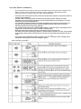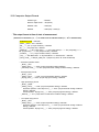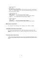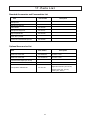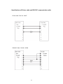
1
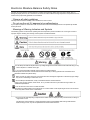
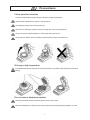
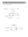
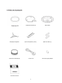
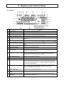
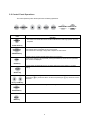
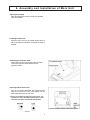
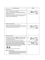
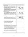
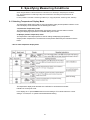
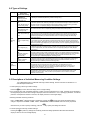
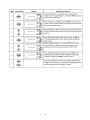
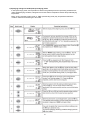
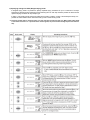
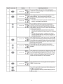
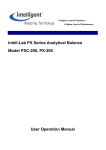
A Higher Level of Precision… A Higher Level of Performance Intell-Lab™ Moisture Analysis Balance MOC-120H User Operation Manual January 2009 Electronic Moisture Balance Safety Notes Improper use of the electronic moisture balance in violation of the following safety notes may result in death, injury or damage to property due to fire, etc. Furthermore, the electronic moisture balance has high temperature components which can cause burns if proper safety guidelines are not followed. �Observe all safety guidelines Carefully read and observe all safety notes included in this user’s manual. �Do not use the unit if it appears to be malfunctioning If you suspect a problem or malfunction in the unit, discontinue use and immediately have the unit inspected by certified service personnel. �Meanings of Warning Indicators and Symbols The following symbols are used in this operating manual and product to prevent accidents from occurring as a result of improper usage or handling. The meaning of each symbol is as described below. Do not attempt to measure samples which may undergo dangerous chemical reactions when heated as doing so may result in explosion or release of toxic gas. Do not place flammable materials near the electronic moisture balance. Some parts of the electronic moisture balance become extremely hot during operation and could lead to fire if flammable materials are placed nearby. Never use with any power source for which the product was not designed. Application of excessively high voltage may result in overheating to malfunction or fire. Do not attempt to disassemble, modify or rebuild the electronic moisture balance. Doing so may result in accident, electric shock, etc. If you believe the unit may be malfunctioning contact to an authorized representative. Do not allow the unit to come in contact with water. The electronic moisture balance is not waterproof. Do not allow water or other liquids to get into the unit’s enclosure as this may lead to electric shock or malfunction. Do not touch the heat-dispersing component of the heater cover or sample pan with your bare hands, as doing so might result in burns. This electronic moisture balance is at high temperature during and immediately after making measurements. When touching the unit, only use the specified control knobs and accessories. Contents 1. Precautions .............................................................................................. 1 2. Description of Features and Principles of Operation ........................... 3 2-1 Principles of Operation ................................................................................................ 3 2-2 Features ....................................................................................................................... 3 2-3 Applications (i.e., materials which can be measured) ................................................ 3 3. Specifications .......................................................................................... 4 4. Names of Individual Parts and Components ......................................... 5 4-1 Names of Parts of Main Unit ....................................................................................... 5 4-2 Parts and Accessories.................................................................................................. 6 5. Display and Control Panel ...................................................................... 7 5-1 Display ................................................................................................ .......................... 7 5-2 Control Panel Operations ............................................................................................ 8 6. Assembly and Installation of Main Unit .................................................. 9 7. How to Conduct Measurements .............................................................. 13 8. Specifying Measuring Conditions ........................................................... 16 8-1 Selecting Temperature Display Mode ......................................................................... 16 8-2 Types of Settings .......................................................................................................... 17 8-3 Descriptions of Individual Measuring Condition Settings ............................................ 17 8-3-1 Selecting the CONDITIONS (Measuring conditions storage area) ............... 18 8-3-2 Selecting the MODE (Measuring mode) ........................................................ 19 8-3-3 TEMP (Drying temperature) Setting ............................................................... 28 8-3-4 Bias Setting ..................................................................................................... 29 9. Menu Settings .......................................................................................... 30 9-1 Types of Menu Settings................................................................................................ 30 9-2 Descriptions of Individual Menu Items ........................................................................ 30 9-2-1 9-2-2 Selecting a measurement base and switching the % display ...................... 31 Specifying the type and format of output ...................................................... 32 9-2-3 Specifying sample codes ...............................................................................35 9-2-4 Setting the date and time ..............................................................................36 9-2-5 CAL (Balance calibration) .............................................................................37 9-2-6 Specifying a device ID ...................................................................................38 9-2-7 Specifying a password ..................................................................................39 10. Error Messages ........................................................................................40 11. Precaution on Conducting Measurements ........................................... 41 12. Predictive Measurements .......................................................................42 12-1 A Description of Predictive Measuring ...................................................................... 42 12-2 Procedure for Obtaining Predicted Measurements ................................................. ................................ ....................................................................................................44 12-2-1 Calculating the bias to be specified when operating in predictive measurement mode ..................................................................................... 44 12-2-2 Evaluating Predictive measurements ............................................................ 46 12-2-3 Performing Predictive measurements ........................................................... 47 13. Temperature Calibration (Option required) ........................................... 48 14. Printing Output to a Printer (Option) ..................................................... 50 14-1 Printer Output Sample ................................................................................................ 50 14-2 Outputting Stored Measurement Data ....................................................................... 53 15. Computer Interface ..................................................................................54 15-1 RS-232C Interface Specifications ............................................................................. 54 15-2 Setting Up and Transmitting Data ............................................................................. 55 15-2-1 Connecting the RS-232C cable ..................................................................... 55 15-2-2 MOC-120H settings ....................................................................................... 55 15-2-3 Setting Up the Computer ............................................................................... 55 15-2-4 Starting Up the Computer ..............................................................................57 15-3 Computer Output Format ........................................................................................... 58 16. Maintenance ............................................................................................. 60 16-1 Performing Maintenance ............................................................................................ 60 16-2 Replacing Fuses ........................................................................................................ 61 17. Parts List .................................................................................................. 62 1. Precautions Follow operation instruction ~ Correctly set draft shield, sample pan supporter, sample pan handler and sample pan. ~ Hold the handle of heater lid when opening or closing heater lid. ~ Use sample pan handler when removing sample pan. ~ Never touch any metal parts of heater unit and surrounding parts when removing sample pan. ~ Cool the unit down to ambient temperature in a safe location after measurement. ~ Always make sure that the unit has cooled down sufficiently before covering it with a dust cover. Warning on high temperature ~ The shadowed parts become especially hot during measurement. Only handle the parts marked with circles when operating. Do not measure hazardous samples ~ Set the drying temperature within the safe temperature range of each sample. ~ Note that the temperature on sample pan can become higher than the drying temperature specified in 'TT' mode. 1 ~ Do not measure any sample which might explode, ignite or produce toxic substances under high temperature. ~ Do not measure any sample which might cause chemical reaction under high temperature. ~ Do not measure any sample of unknown property. ~ Do not measure any sample whose surface hardens or solidifies by heating causing high inner pressure. ~ Immediately turn the power off if the sample should catch fire during measurement. ~ Use with adequate ventilation and appropriate venting for sample type. Do not place flammable objects near the unit ~ The unit becomes very hot during and after measurements. Do not place any flammable objects near it as they may catch fire. ~ Do not place near any objects which are not heat resistant. They may be damaged or deformed. ~ Never place anything on top of the heater unit. ~ Immediately turn the power off and disconnect power cable when any emergency occurs, such as abnormal smell, smoke or fire. Key and Power Switch Operation ~ Do not turn the power on while pressing any keys. ~ Do not operate any keys except as instructed in this manual. ~ Turn the power off and disconnect power cable when lightning is expected. Emergency Stop ~ [Start/Stop] key is always effective during measurement. Press it immediately when any danger or abnormality occurs. Installation, Transportation and Storage ~ Avoid locations subject to extremely high or low temperature, high humidity, direct sun light, electro-magnetic noise, corrosive gas or dust. ~ Install on a vibration-free, level surface. ~ For transportation, hold the unit level as much as possible. ~ Do not drop or impact the unit. ~ Do not pull the cable - hold the connecter when disconnecting the power cable or RS-232C cable. ~ Turn the power switch off and disconnect from the power source when not using for a long time. 2 2. Description of Features and Principles of Operation 2-1 Principles of Operation This unit determines the moisture and solid contents of samples by heating them using infrared illumination and measuring changes in mass due to evaporation. This is referred to as the drying loss method and is the simplest method for determining moisture content and thus mandated by many public regulations related to measurement standards. 2-2 Features � UniBloc sensor 1 The core mechanism of the internal precision balance is the UniBloc* cell which provides excellent responsiveness, 1 temperature characteristics, and shock resistance. This UniBloc* sensor ensures excellent reliability in moisture content measurements over a long period of use. � New Auto Taring Function The MOC-1 20H comes with an internal Auto Taring Function which makes it possible to perform reset correction while performing measurements, thus eliminating drift of the balance even when performing measurements over a long time and making it possible to obtain extremely reliable measurements. � Mid-infrared quartz heating lamp The MOC-120H uses a mid-infrared quartz heating lamp (with a central wavelength of 2.6 µ m). This heater provides excellent drying efficiency over a wide range of diffe rent types of sample, minimizes the differences in heating due to the different colors of samples, and eliminates the overheating of sample surfaces, thus making it possible to obtain ideal drying conditions. What‘s more, this heating lamp also provides a long service life 5 to 10 times greater (20,000 to 30,000 hours) than older infrared or halogen lamps. � A wide selection of measuring modes The MOC-120H provides a wide selection of measuring modes (automatic operation mode, timed operation mode, highspeed drying mode, low-speed drying mode, stepped drying mode, and predictive measuring mode) which makes it possible to perform measurements under the best drying condition for each sample. � The ability to store measuring conditions The MOC-120H provides 10 measuring conditions storage areas which may be used to store sets of measuring conditions to be used for different types of samples, thus reducing the work of programming settings before each measurement. � Data memory The MOC-1 20H is able to store up to 100 pieces of measurement data in memory, making it possible to output large batches of data all at one time. � Printer port The MOC-120H is equipped with a printer port which may be used to connect to the optional printer, thus making it possible to print out text or graph data showing final measurements or intermediate drying states while performing measurements. � The ability to display changes in moisture content (~ M) in a numeric and bar graph display The change ~ M in moisture content over 30-second intervals is displayed in a numeric and bar graph display, thus making it easier to estimate when a measurement should be completed. This feature is also useful in helping to determine measurement completion conditions. 2-3 Applications (i.e., materials which can be measured) ~ Materials for which water is the only or main component which evaporates as a result of heating ~ Materials for which no dangerous chemical reactions or other changes occur as a result of heating * Measurements can be performed with virtually any material meeting these conditions. 3 3 . Specifications Measurement format : Evaporation weight loss method (Heat drying and weight loss method) : Sample weight 0.5g - 120g Minimum display : Moisture content: 0.01% Weight: 0.001 g : Moisture content (wet base & dry base), weight, solid content Measurable quantities 1 Reproducibility (Standard deviation)* : Samples with a weight of 5 g or higher less than 1 0g: 0.05% Samples with a weight of 10 g or higher: 0.02% * When using standard samples and measuring conditions. 1 Measurement modes : Automatic operation mode Timed operation mode (with measurement times of 1 ~240 minutes or continuous measurement mode, with a maximum measurement time of 12 hours) High-speed drying mode (may be used with either automatic or timed operation mode) Low-speed drying mode (may be used with either automatic or timed operation mode) Stepped drying mode (performs drying in 5 steps) Predictive measuring mode Heater temperature range : May be set within a range of 30 to 200°C in 1°C increments (sample position temperature) Display : Backlit LCD display (137 x 43 mm) External output : RS-232C interface : Allows for data output using WindowsDirect function Communications Storage of measurement conditions : Allows for storage of 10 sets of measurement conditions Data memory : Allows for storage of 100 pieces of data Temperature/humidity operating range : 5~40°C, maximum of 85% RH Heat source Medium frequency infrared quartz heater (maximum 625W) Power supply AC 100~1 27/220~240V (50/60 Hz) Power consumption Maximum of 640W Weight and external dimensions : 4.5 kg, 220 x 415 x 190 mm (W x D x H) Sample pan : SUS sample pan (Diameter: 2 sample pans, 2 sample pan handler, wind shield, sample pan supporter, spoon, spatula, 2 spare 8A-fuses, 20 aluminum foil sheets, 130 mm; Depth 13 mm) power cord, three-prong plug adapter, Instruction manual Items included : Optional equipment Printer set (includes DPU-414 printer, printer interface cable printer paper 1 roll, and AC adapter), printer paper (10 rolls), package of aluminum foil sheets (500 sheets), RS-232C cable, Temperature : calibration kit 4 4. Names of Individual Parts and Components 4- 1 Names of Parts of Main Unit 5 Sample pan handler (2) Sample pan supporter Aluminum foil sheets (20) Spoon and spatula (1 each) Power cord Instruction manual 6 Wind shield Spare 8A-fuses (2) Three-prong plug adapter 5 . Display and Control Panel 5-1 Display 0 4 - = ~ 6 5 Display as it appears with the power on. (All display items shown.) Item Name Stability indicator Description This indicator lights up when the balance is stable. Measuring completion indicator This indicator lights up when measuring has been completed. Heater indicator This indicator flashes whenever the heater is on. Predictive measurement indicator This indicator lights up when performing predictive measurements. Preparatory measurement indicator This indicator lights up when measuring has been completed after performing a preparatory measurement. 1 2 3 4 5 Menu display (during menu selection) 6 7 Displays individual menu items in sequence each time the Measuring conditions display (during condition setting) Flashes to display individual items in sequence each time the key is pressed after pressing the key. key is pressed after pressing the key. Values may be specified for a given item when it is flashing. 8 Measuring conditions storage display* Displays the reference number of the currently selected measuring conditions program. Measuring mode display* Displays the currently selected measuring mode. 10 Predictive measurement convergence conditions display* Displays the conditions for convergence of measured values when operating in predictive or comparative mode. When operating in high-speed drying mode, used to display the conditions required in order to maintain a temperature of 180°C. 11 End conditions display* 9 Displays the currently selected end conditions. When the value is displayed as a percentage, it indicates that measuring will end automatically, and when value is displayed in minutes, it indicates that measuring will end when the specified amount of time is reached. Drying temperature display* Displays the currently selected drying temperature. Bias display* Displays the moisture (or solid) bias. 12 13 When measuring weight (i.e., when in idling mode), used to display the weight in grams. When performing measurements, used to display the moisture content and solids content as percentages. When measuring weight, this display is also used to display ‘oL’ (overload) when the weight exceeds the maximum measurable weight and to display ‘–oL’ (negative overload) when the weight does not reach the minimum measurable weight. 14 Moisture/Solid/Weight display 15 Temperature display When 'TT' mode is selected, displays the temperature near the heater with °C symbol illuminated. When 'ST' mode is selected, displays the sample position temperature with °C symbol blinking. *Refer to 8.1 for the details of 'ST' and 'TT' modes. Measuring time display Displays the amount of elapsed time during measuring. 17 Change in moisture (solid) content display Displays the change ~M in moisture (or solid) content at 30-second intervals during measurement. 18 Change in moisture (solid) content scale display Displays the change ~M in moisture (or solid) content in scalar format. The scale may display a maximum change of 2 percent/30 seconds. 16 * Items marked with an asterisk display as flashing items during condition setting. 7 5-2 Control Panel Operations The control panel keys are used to perform the following operations. TARE/RESET START/STOP Name Operation Used to start measuring or to abort a measuring operation. Also used to turn off the alarm which sounds to indicate that a measuring operation has been completed. START/STOP key Used to deduct the tare weight. Also used to perform a reset after an error has occurred. Also used to return to display of weight after completion of measurement. TARE/RESET key Used to confirm currently selected settings during menu selection. When further settings must be specified, pressing the ENTER key causes the next specifiable item choice to be displayed. ENTER key Used to display the selectable items or for setting values during menu selection or condition setting. SELECT key Used for numerical settings. Pressing the decrease. key causes the value to increase, and pressing the UP key / DOWN key Used to enter and exit the measuring condition setting mode. CONDITION key Used to enter and exit the menu selection mode. MENU key 8 key causes the value to 6 . As s embly a nd I ns tal lati on of Ma i n Uni t 1 Opening the package Open the package and check to make sure all listed items are included. 2 Installing the main unit Place the main unit on a flat, stable surface where it will not be subject to vibrations or exposed to drafts or breezes. 3 Removing the protective sheet When using the unit for the first time after purchase, remove the protective sheet attached to pan supporter column. 4 Ensuring that the unit is level Turn the two height adjustment legs located at both sides of the lower rear of the unit to adjust until the level bubble falls within the red circle. * The level is located to the left of the control panel. The instrument is level if the bubble appears in the center of the red circle when viewed from directly above. Level is located to the left of the control panel. ●B u bb le 9 5 Installing the wind shield Open the lid of the heater, hold the wind shield by the knobs on the top, and place it on top of the pan supporter column so that the two round holes in the wind shield fit over the stays. * Place the wind shield firmly into position so that it does not come into contact with the black pan supporter column located at the center of the weighing unit. 6 Attaching the sample pan supporter Place the sample pan supporter gently into the pan supporter column at the center of the main unit. Make certain that the round hole of the sample pan supporter fits smoothly over the stay on pan supporter column. 7 Attaching the sample pan handler Next, attach the sample pan handler. Make certain that one of the grooves of the handler fit smoothly over the projection located at the rear of the wind shield. * The handle may be placed either to the left or right, in the position you find easiest to use. 8 Placing the sample pan Place the sample pan gently down onto sample pan supporter. 10 9 Close the heater lid 10 Connecting the power cord Insert the female end of the power cord into the power inlet located at the rear of the unit. Then, attach the three-prong plug adapter to the power cord plug and insert the plug into power socket. 11 Connecting the printer (optional) If you use the optional printer, connect the printer with the provided printer interface cable. For instructions on how to use the printer, see the separately provided DPU-414 Printer User’s Manual. * Some parts must be oriented in a fixed direction for assembly. Note that placing parts in the wrong direction may prevent heater from closing or in erroneous readings being obtained, and that you should accordingly take care that all parts are put into place in their proper positions. 12 Checking the power settings Check the power conversion switch located on the rear of the main unit to make sure that it is set to the proper voltage setting for your power source. If not, turn the switch to the correct position. * Note that an error will occur if this switch is not set to a position matching the power source being used. 11 ~ Specifying the power voltage setting The specifiable voltages differ depending on the power setting with the power conversion switch described in 12 Note: This setting must be done according to the power voltage available at the installation site. ~ How to specify the power voltage setting 12 7. How to Conduct Measurements Before beginning measurement, check to make sure that there is nothing remaining in the sample pan. Also be sure that all parts of the main unit are firmly fixed into place and be sure that the heater lid has been closed firmly before starting to perform measurements. Also be sure to check on a regular basis that the main unit is level and readjust the height adjustment legs if necessary. (See “6. Assembly and Installation of Main Unit” on p. 9 for instructions on how to do so.) 13 14 15 8 . Specifying Measuring Conditions When using this tester to measure moisture or solid content, it is necessary to first specify the conditions (e.g., drying temperature or measuring mode) of the measurement. The settings to be specified are described below. It is also possible to save sets of measuring conditions (i.e., drying temperature, measuring mode, and bias). 8-1 Selecting Temperature Display Mode The temperature display that is used for drying temperature setting and temperature indication on the main unit display can be selected from the following two modes. TT (Thermistor Temperature) mode The temperature detected by the thermistor (temperature sensor) near the heater is used for setting and displaying temperatures. The default setting is this mode. ST (Sample position Temperature) mode The temperature at the sample position is used for setting and displaying temperatures. Sample position temperature is converted from the temperature detected by the thermistor near the heater. ~ How to select temperature display mode The temperature display mode selected here is effective for all measurement modes. Indication of currently set mode: In the display, the °C symbol blinks when the current setting is 'ST' mode and when the current setting is 'TT' mode, the °C symbol is illuminated without blinking. 16 8-2 Types of Settings Setting Description Display during specification of setting CONDITION CONDITION 0~9 (Measuring conditions storage areas 0~9) AUT (AUTO: Standard drying & Automatic ending mode) TIM (TIME: Standard drying & Timed ending mode) RPD (RAPID: High-speed drying mode) MODE (Measuring mode) SLW (SLOW: Low-speed drying mode) Used to select the area to store condition settings. There are 10 storage areas labeled from 0 to 9. (See “8-21 Selecting the CONDITIONS (Measuring conditions storage area)”.) In automatic operation mode, measuring is brought to a end whenever the change in moisture content over two consecutive 30-second periods falls below the specified conditions for automatic ending. (For further information, see 8-2-2 “1 Specifying settings for AUTO (Automatic ending) mode”.) In timed operation mode, measuring is ended when the elapsed time reaches the specified measuring time. (For further information, see 8-2-2 “2 Specifying settings for TIME (Timed operation) mode”.) In high-speed drying mode, the sample is dried at a temperature of 180°C until the amount of change in moisture content over a 30-second interval falls below a specified value and then drying is continued at a specified drying temperature. (For further information, see 8-2-2 “3 Specifying settings for RAPID (Highspeed drying) mode”.) In low-speed drying mode, the temperature is raised more gradually than when performing measurements under normal conditions, taking about 5 minutes from the time when measuring begins until the temperature reaches the specified drying temperature. (For further information, see 8-2-2 “4) Specifying settings for SLOW (Low-speed drying) mode”.) STP (STEP: Stepped drying mode) In stepped drying mode it is possible to specify a separate drying temperature and separate measuring time over up to 5 step intervals. (For further information, see 8-2-2 “5) Specifying settings for STEP (Stepped drying) mode”.) CMP (COMPARE: Preparatory measuring mode for Predictive mode) Preparatory measuring mode is used for determining the bias (i.e., the difference between the measurement corresponding to that obtained in automatic operation mode and the predicted measurement value) needed in order to perform measurements in predictive measuring mode. (For further information, see 8-2-2 “6) Specifying settings for COMPARE (Preparatory measuring) mode”.) PRD (PREDICT: Predictive measuring mode) In predictive measuring mode, the intermediate results of drying are used to predict future changes and to calculate the result and thereby shorten the measurement time. (For further information, see 8-2-2 “7) Specifying settings for PREDICT (Predictive measuring) mode”) TEMP (Drying temperature) 000 BIAS 0.00 This parameter may be used to specify the drying temperature. The temperature may be set anywhere within a range of from from 30°C to 200°C in 1-degree increments. (30°C to 180°C in 'TT' mode) (For further information, refer to 8-1 Selecting Temperature Display Mode, 13. Temperature Calibration and “8-2-3 TEMP (Drying temperature)”.) This parameter is used to specify a numeric value to be used to correct measurements for bias. A bias anywhere in the range of from –9.99% to 9.99% may be specified in 0.01% increments. (For further information, see “8.2.4 Bias”.) 8-3 Descriptions of Individual Measuring Condition Settings For a detailed description of individual measuring condition settings, see the instructions in subsection 8-2-1 and subsequent subsections. 1 To start specifying measuring condition settings: Press the key at a time when the display shows a weight reading. 2 If any password other than the default password of ‘0000’ has been specified, then a ‘PASS’ message will be displayed in the weight display area. When this message is displayed, follow the instructions in “9.2.7 Specifying a password”, to enter the password. If the password entered is incorrect, the display will return to the weight display. 3 Selecting individual measuring conditions: First a ‘ C ONDI TI ON S’ message will flash on the display. Pressing the key at this time causes the flashing item to change in sequence from M O D E ~ T E M P ~ B I A S ~ C O N DI T I O NS and back to M O D E each time the key is pressed. When the item you wish to specify is flashing, press the key. Specify the settings for that item. 4 To finish specifying measuring condition settings: Pressing the key when any settings item is flashing causes the settings specified to take effect and causes the display to return to the normal weight display. 17 8-3-1 Selecting the CONDITIONS (Measuring conditions storage area) Below is described the procedure used to select the area in which measuring conditions are saved. This operation causes the measuring mode, drying temperature, bias, and other currently specified measuring conditions to be saved to the selected area. * At the time of shipment, the following settings are stored in measuring conditions storage areas 0~9: Measurement standard Drying temperature Measuring mode : Wet Base : 120°C : Standard drying & Automatic ending mode (Change in water content of 0.05% over 30seconds) Bias : 0.00% ~ Specifying settings for the CONDITIONS (Measuring conditions storage area) 18 8-3 -2 Selecting the MODE (Measuring mode) The ‘MODE’ (measuring mode) setting is used to specify the conditions under which measuring is to be completed. As shown in the table in subsection “8.1 Types of Settings”, the mode may be set to automatic operation mode, timed operation mode, or any one of five other modes. 1) Specifying settings for AUTO (Standard drying Automatic ending) mode In this mode, measuring is brought to a end whenever the change in moisture content over two consecutive 30-second periods (i.e., over a period of 1 minute) falls below the specified conditions for automatic ending. Automatic ending conditions may be specified in 0.01-percent increments anywhere in a range from 0.01 to 0.1 percent. Specifying a smaller percentage causes measurements to closely approach a point of equilibrium, but more time is required for measurement. Specifying a higher percentage lessens the amount of time required for measurement, but measuring is stopped while there is still a wide variation in measurements. The automatic ending conditions should be specified in accordance with your objectives and the type of sample being measured. 19 2) Specifying settings for TIME (Standard drying & Timed ending) mode In this mode, the measuring time is specified beforehand. When the specified measuring time is reached, measuring is ended. Measuring time may be specified in 1-minute increments anywhere in a range from 1 to 240 minutes or measuring may be specified to be performed over a continuous period of 12 hours. 20 3) Specifying settings for RAPID (High-speed drying) mode High-speed drying mode is useful for measuring samples with high levels of moisture content. In high-speed drying mode, the sample is dried at 180°C until the change ~ M in moisture content over a 30second period becomes lower than setting, then drying will be continued at the specified drying temperature. The RAPID ~ M threshold specifies when high speed drying (1 80°C) will end. The threshold of RAIPID ~ M may be specified in 0.1-percent increments anywhere in a range from 0.1 to 9.9 percent. * The actual time may vary depending on the specified temperature, but it generally takes about 2 minutes for the temperature control to automatically shift from 180°C to the specified temperature. While specifying a lower RAPID ~M threshold lessens the amount of time required for measurement, depending on the sample it may become burned making it impossible to obtain an accurate measurement. Specifying a higher threshold shortens the time over which a temperature of 180°C is maintained and reduces the effects of rapid drying. Either ‘AUTO’ (automatic ending) or ‘TIME’ (timed ending) may be specified to define the conditions under which measuring is to be ended. 21 22 4) Specifying settings for SLOW (Low-speed drying) mode In low-speed drying mode, the temperature is raised more gradually than when performing measurements under standard drying conditions, taking about 5 minutes until the temperature reaches the specified drying temperature. Either ‘AUTO’ (automatic ending mode) or ‘TIME’ (timed ending mode) may be specified to define the condition under which measuring is to be ended. 23 5) Specifying settings for STEP (Stepped drying) mode In stepped drying mode it is possible to specify separate drying conditions for up to a maximum of 5 steps. Specifying a separate drying temperature and measuring time for each step makes it possible to determine the optimum drying conditions for any sample type. In Step 1, timed ending mode must be specified as the ending condition. In Step 2 and subsequent steps, it is possible to select between either automatic ending mode or timed ending mode. * If automatic ending mode is selected in Step 2 or later, that step becomes the final step. When timed ending mode is selected and a value of ‘0’ is specified as the measuring time, the previous timed ending step becomes the final step. 24 25 Note: Read Section 12 before use of this part. 6) Specifying settings for COMPARE (Preparatory measuring) mode Preparatory measuring mode is used to calculate the bias (i.e., the difference between the measurement results which would be obtained in Standard drying & Automatic ending mode and predictive measuring mode) needed for predictive measurements. Prior to predictive measurements, this mode should be used first to seek the bias. (For further information, see “ ●Preparatory measuring mode” and “ ●Predictive measuring mode”.) 26 Note: Read Section 12 before use of this part. 7) Specifying settings for PREDICT (Predictive measuring) mode Predictive measuring mode is used to predict the change in moisture content and calculate the predicted final measurement before drying has been completed. Thus measuring time can be saved. Note that some materials have properties which make it difficult to obtain accurate predictions. Measurements in preparatory measuring mode must be performed to check the precision of measurement and determine the possible effectiveness of Predictive Measurement in terms of shortening the measuring time. 27 8 -3-3 TEMP (Drying temperature) Setting The following describes the procedure to specify the drying temperature in conducting measurements. While the default drying temperature is 120°C, depending on the type of sample, its moisture content, or other conditions the proper drying temperature may vary. To find the proper drying temperatures for different types of materials, conduct repeated measurements until you find the correct temperature to use for each material. The drying temperature may be set within the range from 30°C to 200°C (from 30°C to 180°C in 'TT' mode) in 1-degree increments. Note that the drying temperature refers not to the temperature of the sample but the temperature of the temperature sensor. The actual temperature of samples during drying may vary depending on the color of the sample, its moisture content, or the type or form of the sample. Generally speaking, drying is performed more quickly when a higher drying temperature is specified, but if the temperature specified is too high it might result in the sample becoming burned, thus making it impossible to obtain accurate measurements. ~ Specifying settings for the TEMP (Drying temperature) 28 8 -3-4 Bias Setting When necessary, measurements can be corrected with bias. A bias anywhere in the range of from – 9.99% to 9.99% may be specified in 0.01% increments. A bias should be specified in cases such as below described. � There are cases where measurement results with the MOC-1 20H fail to meet with expected (standard) values as moisture measurements are the result of various conditions. The bias may be set to adjust the measured value by the MOC-1 20H to the expected (standard) value. Thus, the measured value using the MOC-1 20H can be treated to be equivalent to the existing (standard) measuring method. In most cases it is possible to match the expected (standard) values by optimizing the measuring conditions, but when such conditions would cause the sample to be burned, because the time required is too long, or result in other problems, a bias should be specified. � When using more than one moisture balance unit, there may be cases where it is impossible to obtain identical measurements even when the same measuring conditions are used because of small differences in the surrounding environment. In such cases, set the bias of the unit that is to serve as the standard to zero and set the bias of the other units set to account for any such differences. For information on how to specify the bias when operating in predictive measurement mode, see, “12-2-1 Calculating the bias to be specified when operating in predictive measurement mode”. ~ How to set the bias 9. Menu Settings MOC-1 20H provides the capability to specify and select between different measurement bases, data output formats, and other menu settings. All desired settings should be specified before conducting measurements. The procedure used when changing menu settings is the same as the procedure used when specifying menu settings for the first time. Note that menu settings are automatically internally saved, and that there is no need to specify menu settings before each measurement. 9-1 Types of Menu Settings Menu Menu display (Menu items) Step 2 Step 1 minimum display (%) UNIT (Measurement base) MW (Wet base) MD (Dry base) SOL (Solid) OUTPUT (Measurement data output) 0.01 0.1 Step 1 Step 2 PC (Output to computer) Description Used to select one of three possible measurement bases. It is also possible to switch % display. (For further information, see “9-2-1 Selecting a measurement base and switching % display” on p. 30.) Step 3 30S (30 secs.) 1 M (1 min.) 2M (2 min.) 5M (5 min.) TBL (Output in tabular format to printer) 10M (10 min.) GRP (Output as graph to printer) FIN (Final result) 0 . 0 0 % CODE (Sample code) 0 0 0 0 DATE (Date & time) CAL (Calibration) 0 . 0 0 % Step 1 Used to specify the format in which data is to be output to a printer or computer. The user may select the external device to which output is sent and the format in which data is to be output. When graph output (‘GRP’) has been selected, it is also possible to specify the minimum and maximum values to be used in the range of measurements. (For further information, see “9-2-2 Specifying the type and format of output” on p. 31.) Used to specify the sample code to be output to printer or computer. (For further information, see “9-2-3 Specifying sample codes” on p. 34.) Step 2 Step 3 Step 4 YMD Year Month/Day Time MDY Month/Day Year Time DMY Day/Month Year WCAL (Balance calibration) Time Used to set the internal clock. This date and time is output as the ‘Measurement time’ printed together with any output data to a printer or computer. (For further information, see “9-2-4 Setting the date and time” on p. 35.) Used to calibrate the balance. (For further information, see “9-2-5 CAL (Balance calibration)” on p. 36.) * In addition to these settings, it is also possible to specify other settings such as the device ID (see “9-2-6 Specifying a device ID” on p. 37) or password (see “9-2-7 Specifying a password"). 9-2 Descriptions of Individual Menu Items Descriptions of individual menu items are given in subsection 9-2-1 and below. Menu operation 1 Calling up menu settings: To call up menu settings, press the 2 Selecting individual menu items: When the key from the weight display. key is pressed, the menu item ‘UNIT’ will light up. Pressing the key here causes the menu item lit up to change from ‘UNIT’ ~ ‘OUTPUT’ ~ ‘CODE’ ~ ‘DATE’ ~ ‘CAL’ and back to ‘UNIT’ in sequence each time the settings is displayed, press the key is pressed. When the item for which you wish to specify key. The settings for the selected item may then be specified. 3 Exiting from menu settings: Pressing the key when any menu item is currently lit up exits from menu settings mode and returns to the regular weight display. 30 9-2-1 Selecting the measurement base and switching the % display 1) Selecting the measurement base This menu item is used to specify what measurement base is to be used in measurements. There are three different types of bases: wet base, dry base, and solid. The type of base specified should be selected in accordance with the sample being measured. Type Wet Base Menu display MW Formula x 100 (%) Percentage of evaporated moisture weight with respect to the weight before drying. x 100 (%) Percentage of evaporated moisture weight with respect to the weight after drying. x 100 (%) Percentage of residual weight after drying with respect to the weight before drying. W Dry Base Solid MD SOL Description W –D W –D D D W Notation used in formulas: W: Wet weight before measurement D: Dry weight after measurement (While measurement is being performed, the weight at each point in time is used as the dry weight in calculating measurements.) 2) Switching the minimum display of percentage This menu item is used to switch the minimum display of the measurement result between 0.1% and 0.01%. ~ How to select a measurement base 31 9 -2 -2 Specifying the type and format of output The MOC-1 20H may be connected to the optional printer or computer so that measurement data can be output. 1 There are three types of output formats as shown in the table below. External device Computer Printer Output format Numeric Menu display PC Description This is the setting which should be selected when using the “Windows Direct Function” or some other software to output data through the RS-232C interface. Numeric TBL This setting causes numeric output to the optional printer. Graph GRP This setting causes graph output to the optional printer. 2 Any one of the six output intervals shown below may be selected to specify the frequency at which output is to be generated. The output interval specifies the amount of time which is allowed to elapse during measurement before the next set of output is generated. When there is no need to view intermediate data, ‘FIN’ may be selected so that only the final results are output. * ‘FIN’ should never be selected when graph output has been selected when operating in preparatory measuring mode as that would result in no predicted measurements being output. Output interval Menu display Every 30 seconds 30S Every minute 1M Every 2 minutes 2M Every 5 minutes 5M Every 10 minutes 10M Final results only FIN 3 When graph output has been selected, it is possible to specify the maximum and minimum values of the range of values to be measured in 5-percent increments. Measurement base Range of values to be measured Wet base (%), Solid (%) Minimum: From 0 to (Maximum –5%) (Specified in 5-percent increments; may be set to any value from 0~95%.) Maximum: From (Minimum +5%) to 100 (Specified in 5-percent increments; may be set to any value from 5~100%.) Dry base (%) Minimum: From 0 to (Maximum –5%) (Specified in 5-percent increments; may be set to any value from 0~495%.) Maximum: From (Minimum +5%) to 500 (Specified in 5-percent increments; may be set to any value from 5~500%.) 32 ~ How to specify the output format to be used 33 Specifying the range of measurement values to be used (when ‘GRP’ has been selected) 34 9-2- 3 Specifying sample codes This section describes how to specify sample codes to be used when outputting measurements to the optional printer or a computer. Sample codes may be specified as 4-character codes. � Any digit from 0 to 9, and letter from A to Z, or a hyphen “_” may be specified as the value of the first or second character of the code. � Only digits from 0 to 9 may be specified as the value of the third and fourth character and the code. * The digits in the third and fourth characters of the code are automatically increased by 1 after each measurement, with the value returning to ‘00’ when it would otherwise exceed a value of ‘99’. ~ How to specify sample codes 9 -2-4 Setting the date and time This section describes how to set the date and time. Also note that the date and time of measure ment are output whenever measurement data is output to the optional printer or a computer. ~ How to set the date 9-2 -5 CAL (Balance calibration) The internal balance of the MOC-1 20H may be calibrated at two points: at the 0 and 1 00grams. The MOC-1 20H may also be connected to a printer to make it possible to automatically generate calibration records in compliance with GLP, GMP, and ISO standards. The power to the unit should be turned on at least 30 minutes before calibration is performed in order to ensure accurate calibration. The MOC-120H is extremely sensitive to interference from drafts, breezes, vibration, and other disturbances in the surrounding environment, and care should be taken to ensure that there is no such interference before performing calibration. It is impossible to calibrate the balance accurately immediately after performing measurements or at any other time when the heater lid is hot. Allow the temperature of the heater lid to cool down to ambient temperature before performing calibration. The weights used should consist of standard OIML weights or some other type of non-magnetic Class 1 weights. (The use of Class E2 or Class E1 weights is recommended.) When placing the weight on the sample pan, it should be placed in the center of it. The heater lid must be closed during calibration to prevent influence of drafts or air flow, and the height of the weights used should be such that they do not come into contact with the temperature sensor or heater. If you wish to abort a calibration already in progress, press the displayed and the display will return to the weight in grams. Scale calibration procedure key. An ‘Abort’ message will be 9-2- 6 Specifying a device ID This section describes how to specify the device ID output when outputting data to the optional printer or a computer. The device ID is an 8-character ID which may be set using the following characters: digits from 0 to 9, letters from A to Z, and hyphens ‘—’. ~ How to specify a device ID 37 9 -2-7 Specifying a password In order to prevent the specified measuring conditions from being modified unexpectedly, a password may be specified to prevent other users from changing the specified conditions. The password is 4 characters in length and may be set using the following characters: digits from 0 to 9, letters from A to Z, and hyphen. If any password other than the default password of ‘0000’ is set, then whenever the key is pressed to specify measuring conditions ‘PASS’ is displayed and the user is required to enter the password. ~ How to specify a password 10. Error Messages If any of the following error messages is displayed, follow the procedures described below to check for the cause and take appropriate action. If the error cannot be removed, contact your representative. Message Er102 Description The protective sheet has not been removed. The sample is too light (i.e., under 0.5 grams). Er103 Action to be taken Remove protective sheet located under the pan supporter column. (See item 3 in “6. Assembly and Installation of Main Unit” on p. 9 for instructions.) The minimum weight which may be measured by the MOC-120H is 0.5 grams. Measure again using a sample with a weight of 0.5 grams or greater. Press the message disappear. The sample is too heavy (i.e., over 120 grams). Er104 key to make the error The maximum weight which may be measured by the MOC-120H is 120 grams. Measure again using a sample with a weight of 120 grams or smaller. Press the message disappear. key to make the error Invalid moisture content value (Occurs when weight increases by more than 0.1 grams) This error is displayed when a sample is added during Er201 Invalid moisture content value (Occurs when weight being measured is less than –1 grams) Press the Er202 Balance communications error Turn off the power and then turn the power on again. Invalid calibration weight Use a calibration weight of the correct weight value. Instability during balance calibration Perform balance calibration again with the MOC-120H placed on a flat, stable surface not subject to the effects of external vibration, drafts, or breezes. Power error Turn the power off, make sure that the power conversion switch located on the back is set to the correct position. measurement. Press the disappear. key to make the error message key to make the error message disappear. Er401 Er501 Er502 E r 701 If any of the following errors are displayed, contact your representative. Message Er301 Er302 Er303 Description Temperature sensor failure Heater overheated This error indicates the existence of an extremely hazardous condition. Turn the power off immediately and contact your representative. Heater control failure Er305 Heater lid is open during measurement (for 15 sec.). Er306 Er601 Er602 Er603 Lift mechanism failure Internal clock failure Er802 40 1 1 . Precaution on Conducting Measurements � Precaution on conducting multiple measurements in succession Placing a sample on the sample pan which is already warm may cause moisture from the sample to evaporate before measuring is begun and causes errors in measurement result. Always be sure to use a cool sample pan when performing a subsequent measurement. Allow an even amount of time to elapse between measurements, as errors may occur if the temperature of the balance mechanism varies. Two sample pans and two sample pan handlers are provided for use when conducting multiple measurements in succession. � Use of sample pan and aluminum foil sheets It is impossible to obtain accurate measurements if any of the last measured sample remains on the sample pan. To avoid errors, either wipe the sample pan clear of any remaining sample (see “15. Maintenance” on p. 58 for further instructions) or use disposable aluminum foil sheets. Twenty disposable aluminum foil sheets are included with the unit. � Quantity and placement of powdered, particulate and viscous sample materials Samples cannot be heated properly if they are not placed flatly. Placing samples in mounds or in layers of varying thickness may result in the highest points being burned. accurate measurements. The precision of measurement improves when the samples are flatly and evenly placed and the amount of sample are larger. However, too large sample amount results in uneven heating. Make certain samples are placed correctly. Proper placement Incorrect placement � Measuring liquid samples Since most liquid samples harden and become sticky after drying, it is recommended to use the aluminum foil sheets when measuring such samples. Note that the aluminum foil sheet is waterwettable, thus making it possible to obtain wide and even sample placement and effectively shortening measuring times and obtaining accurate measurements. Depending on the sample, the use of sand to speed up drying (Silica sand or ocean sand with a mesh of 20 or so). 41 12. Predictive Measurements 12- 1 A Description of Predictive Measuring Electronic moisture balance can be used to measure the moisture content of a wide range of materials. This is the most important feature not found in other types of moisture testers. However, because moisture balance operates by heating samples to evaporate the moisture content, it takes a fair amount of time to obtain results. MOC-1 20H has a feature that not only reduces measuring times but also brings the method to adjust partial drying measurement results to those obtained with a standard method of measuring. The feature is called predictive measuring mode. In predictive measurement: (1) The final moisture content is predicted while drying is still in progress. (2) Three additional settings must be specified before measuring: the drying temperature, the predicted value convergence range, and bias. (3) Only sample materials which produce what are usually referred to as S-shaped drying curves can be measured. The bias may also be used to correct for differences in measurements obtained with other moisture content testers. � Drying temperature Since the measurements obtained in predictive measuring mode are treated as comparable to the measurements obtained by automatic operation mode, the drying temperature should be set to the same temperature as in automatic operation mode. � Predicted value convergence range When measuring in predictive operating mode, the predicted values are internally calculated every 30 seconds, and while variation occurs in the calculated values the degree of variation becomes smaller as time elapses. The range of variation in moisture content specified in order to confirm a predicted value as the final is referred to as the predicted value convergence range. The MOC-1 20H treats the predicted value as final when the range of variation falls within the “predicted value convergence range” The predicted value convergence range may be set to a value anywhere from 0.1 to 9.9 percent. Specifying a higher value for the predicted value convergence range causes the final predicted value to be determined quickly. On the other hand, the specification of a higher value may also result in greater degree of error. It is possible to obtain more precise sets of predicted values by specifying lower values. This takes longer to determine the final predicted value. The predicted value convergence range should be specified according to your objectives. Note that the default setting for the MOC-1 20H is a value of 0.5 percent. � Bias Bias is used to adjust the predictive measurement. On the MOC-1 20H, a bias of anywhere from – 9.99 to +9.99 percent may be specified. When performing a preparatory (COMPARE) measurement, the MOC-1 20H automatically indicates the most appropriate bias to be used to correct measurements to match those obtained in automatic operation mode. � Bias can be used for correction against other methods When seeking the bias to perform correction against another method, the bias should be reset to zero and then a number of samples with known moisture contents have to be measured with predictive measurements and the average difference between the known moisture contents and the predicted moisture contents should then be specified as the bias. 42 ~ Preparatory measuring mode In preparatory measuring mode, predicted measurements are displayed while measuring is in progress and measuring is halted under the same conditions as when operating in automatic operation mode. The difference between the measured values of automatic operation mode and predictive measuring mode is displayed as the necessary bias. In order to obtain accurate predicted measurements, it is recommended to perform at least 5 preparatory measurements and take the average to determine the bias. You should also take care in terms of the amount of the sample and the way the sample material is placed onto the sample pan. They must be the same every time and laid out as evenly as possible. ~ Predictive measuring mode Prior to predictive measurements, specify the same drying temperature, predicted value convergence range, and bias as calculated from preparatory measurements. Note that measuring is halted if no predicted measurement has been calculated after 30 minutes have elapsed after starting the measurement. 43 12-2 Procedure for Obtaining Predicted Measurements 1) Use preparatory measuring mode to obtain the appropriate bias value for the predictive mea surement. (See “1 2-2-1 Calculating the bias to be specified when operating in predictive measurement mode” for instructions.) 2) Use the bias obtained in preparatory measuring mode in step 1) to perform the measurement, and evaluate the predicted measurement. (See “12-2-2 Evaluating predicted measurements” for instructions.) 3) Measure in predictive measuring mode. (See “12-2-3 Performing predictive measurements” for instructions.) 12-2-1 Calculating the bias to be specified when operating in predictive measurement mode 44 45 12-2-2 Evaluating predicted measurements 46 12-2-3 Performing predictive measurements 47 1 3 . Temperature Calibration (Option required) Temperature calibration can be performed with the optional temperature calibration kit. The calibration record meeting with GLP/GMP/ISO requirements can be automatically produced with the optional printer. Caution Do not touch heater cover and the sensor probe or holder of temperature calibration kit during temperature calibration as they become very hot. Touching these parts may cause serious burning. ~ The environmental conditions such as ambient temperature and air movement affect temperature calibration. Perform temperature calibration without surrounding air movement and under the same conditions as when performing measurements. ~ Press the key to discontinue a once started temperature calibration. "Abort" is displayed and it returns to the weight display. ~ For the operation of digital thermometer of temperature calibration kit, refer to its instruction manual. Installation of Temperature Calibration Kit (Option) 1 Assembling temperature calibration kit: Insert the sensor probe into the brackets on the holder as shown in the figure. Place the end of sensor probe in the bracket in holder’s center. 2 Open heater cover and place the temperature calibration kit over the sample pan as shown in the figure. (Fit the hole of holder to stay of main unit as shown in the figure.) 3 Confirm heater cover is completely closed and sensor probe is fitting in the notch of heater cover. 48 Temperature calibration procedure The following temperature calibration procedure can be entered only when 'ST' mode is selected as temperature display mode (Refer to 8.1). Verify that the °C symbol in the display is blinking, which indicates that currently selected mode is 'ST' mode. Install temperature calibration kit and switch on digital thermometer in advance. * Select a temperature about 20°C lower than the sample position temperature. Set 80°C if 100°C at the sample position is desired. 49 14 . Printing Output to a Printer (Option) The MOC-120H may be connected to the optional printer to output measurement data. Output includes data consisting of intermediate or final measurements, sample codes, and measurement times. 14- 1 Printer Output Sample ~ Output of final results of more than one measurement [Tabular output (TBL)] 50 ~ Output of the intermediate and final values of a single measurement *Note on the decimal precision of printed weight data Although the minimum weight which may be displayed by the MOC-120H is 0.001 grams, weights are printed to a precision of 4 decimal points because the values printed consist of averages from 7 measurements taken over each 30-second interval for each set of weight data output. 51 ~ Output of the intermediate and final values of a single measurement Maker : SHIMADZU CORP Model : MOC -120H Serial number : D207300000 Device ID : ABCD- 123 Sample code : B-20 Date & time of measurement: 2003/08/08, 15:07 Measuring conditions storage area: 0 Measurement standard: Dry base Temperature display mode: Output only when 'ST' mode is selected Measurement mode: Preparatory measuring mode Drying temperature: 110°C Automatic ending conditions: 0.05% Predicted value convergence range: 0.5 Wet Mass : 5.6892g Elapsed measuring time Changes in drying temperature Measured value (%) : 4.8637g 52 ~ Output of report of balance calibration Maker : SHIMADZU CORP Model : MOC-120H Serial number : D207300000 Device ID : ABCD- 123 Date & time of measurement : 2003/08/08, 15:17 Before calibration : 100.004g After calibration : 100.000g Signature title : SHIMADZU CORP : MOC-120H : D41 2345678 : 00000000 Date & time of measurement: 2004/11/22, 16:09 14- 2 Outputting Stored Measurement Data The MOC-120H can store up to 100 sets of previous measurements data, and the stored data can be output to the optional printer or a computer. To output this data: 1 Follow the directions given on p. 31 in “9-2-2 Specifying the type and format of output” to set the output format to either ‘TBL’ or ‘PC‘. 2 From the weight display, press the key and hold the key down while pressing the key. 3 The data will then be output in order beginning from the most recently measured data. To stop printing while printing is still in progress, press the 53 key. 15. Computer I nterface The RS-232C interface may be used to connect the MOC-1 20H to a computer. 15- 1 RS-232C Interface Specifications Interface type RS-232C Communications method Asynchronous communication Baud rate 2400 bps Data bits 8 bits Parity None Stop bits 1 bit Connector Female D-SUB9 pins Pin assignment Pin number : Direction 1 Description Not used 2 Output TXD 3 Input RXD 4 Not used 5 GND 6 Not used 7 Not used 8 Not used 9 Not used Frame Shield 54 15- 2 Setting Up and Transmitting Data 15-2-1 Connecting the RS-232C cable With the power to the MOC-1 20H and the computer both turned off, connect the RS-232C cable. Connect the RS-232C cable to the RS-232C port located at the rear of the MOC-1 20H and tighten the screws at both sides of the connector. Follow the same procedure to connect the RS-232C cable to the computer. If the MOC-120H has been moved, make sure that the MOC-120H is readjusted the level. (See “6. Assembly and Installation of Main Unit” on p. 9 for instructions.) 15-2-2 MOC-120H settings Turn on the power to the MOC-120H and set the measurement data output format to ‘PC’. (See “9-2-2 Specifying the type and format of output” on p. 31 for instructions.) 15-2-3 Setting Up the Computer (leave the balance unplugged) 1 Turn ON the power to the computer and start ® Windows . 2 Click “Start”, choose “Settings”, and “Control Panel”. 3 Select “Accessibility Options”. 4 Verify that there are no check marks for any items on all five tabs including “General.” 5 Put a check mark at “Support Serial key device” in the “General” tab. This should be the only check mark on all the tabs of Accessibility Options unless “Administrative options” appears in the “General” tab. Put check marks at both the items of “Administrative options” to maintain the settings even after ® restarting Windows . 6 Open “Settings”. 7 Select the serial port corresponding to the RS-232C port of your personal computer. (Serial port: any one of COM1 to 4. Usually, COM1) 55 8 Select a “Baud rate” of 300. 9 Click “OK”. 10 Click “Apply” and wait. 11 Click “OK”. 12 Click “Start”, point to “Shut Down” then select “Restart the computer?”. ® It is not necessary to perform the Windows control panel setting every time. 56 15-2-4 Starting Up the Computer Turn on the power to the computer and when Windows has started up open the Microsoft Excel or whatever software is to be used to read in data. For instructions on how to use your computer, operating system (Microsoft Windows), or software being used, see the user manuals provided with them. The Microsoft Windows name and logo are the trademarks and registered trademarks of Microsoft Corporation. 57 15- 3 Computer Output Format Interface type : RS232C Numeric output format : JIS (ASCII) Delimiter code : 0x09 (tab) Delimiter : 0x0D (CR) + 0x0A(LF) ~ Title output format at time of start of measurement (Underscore characters (i.e., ‘–’) are used below to indicate blanks (i.e., ‘20’ in hexadecimal) _SHIMADZU-CORP” + delimiter “_Model_:_MOC-1 20H” + delimiter “_SN_:_” + “_XX” (1 0-byte Serial No.) + delimiter “_ID_:_” + “_XX” (8-byte ID) + delimiter “_Date/Time_:_” + “XX” (2-byte year) + “.” + “XX” (2-byte month) + “.” + “XX” (2-byte day) + “/” + “XX” (2-byte hour) + “:” + “XX” (2-byte minutes) + delimiter “_Condition_:_” + “X” (1 -byte condition number) + delimiter “_Unit_:_” + “Wet Base Moist.” or “Dry Base Moist.” or “Solid Content” + delimiter "_Temp_mode_:_"+"Sample_plate_tem.," (Output only when 'ST' mode is selected) � Automatic operation format “_Mode_:_Auto” “_Setting Temp._:_” + “XXX” (3-byte temperature setting) delimiter “_Auto Stop Cond._:_” + “X.XX” (4-byte automatic ending conditions setting) + delimiter � Timed operation format “_Mode_:_Time” “_Setting_Temp._:_” + “XXX” (3-byte temperature setting) + delimiter “_Drying_Time_:_” + “XXX” (3-byte drying time setting) + delimiter � High-speed drying format “_Mode_:_Rapid” “_Setting_Temp._:_” + “XXX” (3-byte temperature setting) + delimiter Automatic operation: “Auto Stop Cond._:_” + “X.XX” (4-byte automatic ending conditions setting) + delimiter Timed operation: “Drying Time_:_” + “XXX” (3-byte drying time setting) + delimiter “_Delta M_:_” + “X.X” (3-byte 200°C maintenance condition setting) + delimiter � Low-speed drying format “_Mode_:_Slow” “_Setting Temp._:_” + “XXX” (3-byte temperature setting) + delimiter Automatic operation: “Auto Stop Cond._:_” + “X.XX” (4-byte automatic ending conditions setting) + delimiter Timed operation: “Drying Time_:_” + “XXX” (3-byte drying time setting) + delimiter 58 � Stepped mode format “_Mode_:_Step” tab + “Temp” + tab + “Time” + delimiter The following output then appears the same number of times as the number of specified steps: “_Step” + “X” (1 -byte step number) + tab + “XXX” (3-byte temperature setting) + tab + “XXX” (3byte drying time setting) + delimiter � Comparative mode format “_Mode_:_Compare” “_Setting Temp._:_” + “XXX” (3-byte temperature setting) + delimiter “_Auto Stop Cond._:_” + “X.XX” (4-byte automatic halting conditions setting) + delimiter “_Pred. Tol._:_” + “X.X” (Predicted value convergence range) + delimiter � Predictive mode format “_Mode_:_Predict” ”_Setting Temp._:_” + “XXX” (3-byte temperature setting) + delimiter “_Auto Stop Cond._:_” + “X.XX” (4-byte automatic halting conditions setting) + delimiter � Measurement output format tab + “Time (min.)” + tab + “Temp. (C)” + tab + “Weight (g)” + tab + “Moist (%)” + delimiter � Intermediate measurement output format tab + “XXX.X” (5-byte measuring time) + tab + “XXX” (3 -byte sample pan temperature) + tab + “XXX.XXXX” (8-byte sample weight) + tab + Moisture content “XXX.XX” (6-byte moisture content) + delimiter � Final measurement output format “*” + tab + “XXX.X” (5-byte measuring time) + tab + “XXX” (3-byte sample pan temperature) + tab + “XXX.XXXX” (8-byte sample weight) + tab + Moisture content “XXX.XX” (6-byte moisture con-tent) + delimiter 59 16. Maintenance 16-1 Performing Maintenance Turn the power off and disconnect the power cable. Allow the heater and other parts cool down to ambient temperature before performing maintenance. Removing and reinstalling parts and components Remove the sample pan, then the sample pan handler, sample pan supporter, and wind shield in this order. See “6. Assembly and Installation of Main Unit” on p. 9 for instructions on how to install parts and components. (1) Wipe away any dust or residue of spilled samples. (2) Maintenance of the main unit � Use a soft, dry cloth to wipe away any dirt or soil. � Avoid applying strong pressure when wiping even if you find dirt or soiling difficult to remove. � If you find it particularly difficult to remove dirt or soiling, wet a cloth in water or in water with a small amount of neutral detergent, wring the cloth thoroughly, and wipe. Next, rinse the cloth in water and wring it out to remove any detergent and wipe again and then allow to dry. (3) Maintenance of parts and accessories � Remove the spoon, spatula, sample pan, and wind shield from the main unit and wash in water with a soft sponge. � Reattach to the main unit and wait until they completely dry before using the unit again. * When using detergents, be sure to follow the instructions for use provided with the detergent. * Never use paint thinner, benzene, or any volatile cleaning agents or any abrasive cleansers or polishes. * Never use wire brushes or other hard cleaning tools. 60 16- 2 Replacing Fuses 1 Turn the power off and disconnect the power cord from the unit. 2 The fuse holder is located at the rear of the unit. Insert a slot screwdriver or similar tool from the top of the fuse holder and pull the fuse holder towards you. 3 Remove the fuses from the fuse holder and check if any are burned out. 4 If there are no burned-out fuses, return the fuse holder to its original position. Re- place burned-out fuse(s) with spare fuse(s) (8A). 5 Return the fuse holder to its original position in the main unit. 6 Insert the power cord back into the main unit. * Should the fuse(s) blow out repeatedly after replacement, contact your representative. 61 17. Parts List Standard Accessories and Consumables List Item Part number Sample Pan 321 -63314 Sample Pan Handler 321 -63315 Wind Shield 321 -63316 Sample Pan Supporter 321 -63317 Spoon Spatula Set 321 -63318 Fuse, 8A, 2 pcs Set 321 -63319 Aluminum Foil Sheet 500 pcs Set 321 -63320 Description Optional Accessories List Item Part number Electronic Printer Set 321-63305-02 AC 230V ± 10% Electronic Printer Set 321 -63305-03 AC 120V ± 10% Thermal Printer Paper (10 roll set) 321-63306-08 RS-232C Cable 321-63308 Temperature calibration kit 321 -641 30 62 Description Digital thermometer (321-64136) Sensor probe (321 -641 37) Holder (321 -64131) ~ Specifications of Printer cable and RS-232C communication cable ~Printer cable~ P/N: 321 -63307 ~RS-232C Cable ~ P/N:321 -63308 63 Intelligent Weighing Technology has more than 50 years experience in the weighing industry, both in the USA and worldwide. With contacts in over 50 countries including the USA, we provide you with the weighing equipment you need. When you invest in weighing equipment from Intelligent Weighing Technology, you’re really buying peace of min d. Quality - Scales and balances solidly built from the ground up with superior engineering and components for exacting results. Value - From bench scales to analytical balances, weighing equipment priced for real-world business applications, with superior service and support. Experience - Expert advice to help you choose just the right product for your application. Quality + Value + Experience…it adds up to the Intelligent Investment. Intelligent Weighing Technology, Inc. www.intelligentwt.com © Intelligent Weighing Technology, Inc. All rights reserved worldwide. The information contained herein is the property of Intelligent Weighing Technology, Inc. and is supplied without liability for errors or omissions. No part may be reproduced or used except as authorized by contract or other written permission. The copyright and the foregoing restriction on reproduction and use extend to all media in which the information may be embodies. 64