1
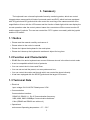
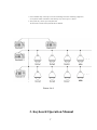
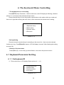
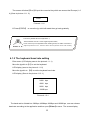
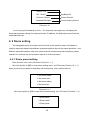
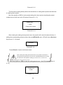
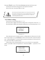
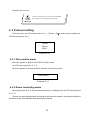
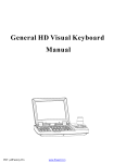
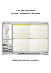
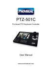
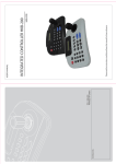
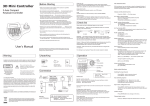
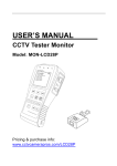
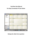
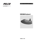
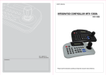
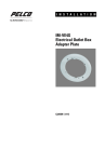
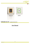
RS485 Surveillance Keyboard Directory 1. Summary ......................................................................................................................... 1 1.1 Notice ..................................................................................................................... 1 1.2 Function and Characteristic ................................................................................... 1 1.3 Technical Data ....................................................................................................... 1 2. Keyboard Connection ..................................................................................................... 3 2.1 Keyboard Interface Instruction ............................................................................... 3 2.1.1 RS42 2 and RS485 interface ....................................................................... 3 2.1.2 RJ45 Interface ............................................................................................. 3 2.2 Matrix Connection .................................................................................................. 4 2.2.1 RJ45 Local Connection ............................................................................... 4 2.2.2 RS422 remote connection ........................................................................... 5 2.3 Connect with the Dome Directly ............................................................................ 5 2.4 The Connection of the Keyboard in the System .................................................... 6 3. Keyboard Operation Manual ........................................................................................... 7 3.1 Electrify to keyboard .............................................................................................. 8 3.2 LCD ........................................................................................................................ 8 3.3 Joystick controls the dome .................................................................................... 9 3.4 Change object dome .............................................................................................. 9 3.5 Dome lens control .................................................................................................. 9 3.6 Dome function operation ...................................................................................... 10 3.6.1 Preset ........................................................................................................ 10 3.6.2 Scan........................................................................................................... 10 3.6.3 Pattern ....................................................................................................... 10 3.6.4 Tour ............................................................................................................ 10 3.7 Cal l the dome main menu ................................................................................... 11 3.8 Control the matrix ................................................................................................ 11 3.8.1 Switch the domes in order ......................................................................... 11 3.8.2 Call main menu of matrix ........................................................................... 11 3.8.3 Confirm after program ............................................................................... 11 3.8.4 Change object monitor .............................................................................. 12 4. The Keyboard Menu Controlling ................................................................................... 13 4. 1 Keyboard Para meter Setting ............................................................................. 13 4. 1. 1 Set keyboard ID ....................................................................................... 13 4.1.2 The keyboard baud rate setting ................................................................. 15 4.1.3 Joystick Calibration .................................................................................... 16 4.1.4 Multi-keyboard Connection state setting ................................................... 17 4.1.5 Keyboard screen brightness ...................................................................... 17 4.1.6 Keyboard message display ....................................................................... 17 4. 2 Dome setting ....................................................................................................... 18 4.2.1 Dome preset setting .................................................................................. 18 4.2 .2 Dome scan setting .................................................................................... 20 4.2.3 Pattern setting ........................................................................................... 21 4.2.4 Tour setting ................................................................................................ 22 4. 3 Protocol setting ................................................................................................... 23 4.3.1 Pelco matrix mode ..................................................................................... 23 4.3.2 Dome controlling mode .............................................................................. 23 4.3.3 DVR controlling mode ................................................................................ 24 4. 4 Exit to keyboard menu ........................................................................................ 24 5. Appendix ....................................................................................................................... 24 5. 1 RS485 Bus Basic Knowledge ............................................................................. 24 5.2 Keyboard shortcut operation manual ................................................................... 28 6. Keyboard Menu Index ................................................................................................... 30 7. Maintenance service terms ........................................................................................... 30 1. Range of warranty ................................................................................................. 30 2. Warranty terms ...................................................................................................... 31 3. Shipping ................................................................................................................. 31 1. Summary The keyboard is an universal keyboard of security monitoring series, which can control integrate dome camera with all kinds of protocols matrix and DVR, which has been equipped with 3D joystick and 2D joystick which can control the revolving of the camera and the zoom magnification of lens; with the LCD screen and the function of back-light; which can display the current operation order the control protocol name the current dome ID the current monitor ID and the state of joysticks. The user can control the CCTV system more easily with the joystick and the LCD screen. 1.1 Notice z Please read the manual carefully and reserve it. z Please advert to the notice in manual. z Please don't place the keyboard in the moist place. z Please don't close up the keyboard to exothermic object for long time. 1.2 Function and Characteristic z RS485 Bus Line and a keyboard can connect 31domes at most in the direct control mode. z It can be compatible with all kinds of protocols z You can control the Iris Locus and Zoom. z You can set and call the preset, run scan pattern and tour. z You can control the matrix and through which can control the dome indirectly. z It has been equipped with the 2D/3D joystick and the larger LCD screen. 1.3 Technical Data Electrical Input voltage 9V-12VAC/DC Rated power 2.5W、 Communication Communication interface: RS485 X1 RS422 X 1, RJ 45 Communication frequency: 2400, 4800, 9600 19200Bps Communication distances: 1.2km (RS485 and RS422 can achieve it) Operational environment Operating temperature:0℃~50℃ 1 Relative humidity:Less than 90% Physical property L * W*H =218* 180 * 55(mm) Weight:630g(Net Weight) 2 2. Keyboard Connection 2.1 Keyboard Interface Instruction There is inter face on the back of the key boa rd, which equipped with kinds of communication interfaces: RS422、RS485、RJ 45,which can connect and control kinds of peripheral equipment. 2.1.1 RS42 2 and RS485 interface RS422 and RS485 interface are on the 6bit ribbon cable connection of the keyboard .RS485 (A + B-) can connect with the dome when the key -board controls the dome directly ;RS485(A+,B-)can connect with DVR or other keyboard when the keyboard controls the dome by matrix ; RS 422 ( T+,T-) is s ending the signal ,RS422(R+,R-)is receiving the signal , both of which can connect with matrix, DVR and son. Picture2-1.1 2.1.2 RJ45 Interface It is the standard net work interface which can be mainly used for connecting with the matrix for short distance (the distance is less than 7.6m). About the details, Please see to “2.3 matrix connection”. 3 6Bit ribbon Cable RJ45 Power Supply Port Picture2-1.2 2.2 Matrix Connection The keyboard can control matrix of PELCO CM6700、CM6800.For example ( following) that the keyboard connects with the PELCO CM 6700 matrix in order to introduce the connection between the keyboard and the matrix. There are two kinds of keyboard connection inter face on the CM6700 matrix back plate: one is local keyboard connection interfaceRJ45(“LOCALKE-YBOARD”) , which can control the single keyboard within the distance of 7.6 m; The other is the remote interface RS 422 ( “REMOTE EYBOARD( s)”),which can connect with the keyboard RS422 interface, the maximum distance is 1200m. 2.2.1 RJ45 Local Connection Please insert one crystal end of RJ 45 connect- ion line into the Rj45interface of the keyboard, and insert the other one into the RJ45inter face(“LO-CALKEYBOARD”)of CM6700matrix. 1. RJ45 local connection, the distance between the Keyboard and the matrix is less than 7.6m. 2. RJ45 interface has 12VAC, it not need other power when the keyboard connect to CM6700 matrix. 4 Picture2-2.1 2.2.2 RS422 remote connection RS422 connection line, one end connects with RS4 22 interface(REM OTE K EY BO ARD( s) ) of CM6700 back plate, the other end connects with RS4 22 interface of the keyboard, the keyboard interface RS 422(R + R-)corresponds with matrix interface RS 422(T + T-), the keyboard inter face RS 422(T+ T-)corresponds with matrix interface RS422(R+ R -). RS422 remote connection, the maximum distance between the keyboard and the Matrixes 1200m. 2.3 Connect with the Dome Directly You can connect with the dome by RS485 inter-face when the keyboard controls the dome directly. The RS485 interface of t he dome is on the switch board of pendent hanger of the upper cover of the dome. You can find the 4 Pin control/power socket and find the corresponding RS485(A+,B-)interface according to the above mark when you turn the metal button inside the hanger and open the switch board. There are different connection ways according to the domes which produce by the different 5 manufacturers. About connection with the dome, please see to the dome installation manual. 2.4 The Connection of the Keyboard in the System The keyboard controls the matrix and then controls the domes indirectly by the matrix (sees to the picture2.4-1) When unconnected with the matrix, the keyboard controls the dome directly. Keyboard and camera parallel connect to RS485 Bus and each keyboard can control each dome. This way is required to have a main keyboard (the main keyboard ID set as 1); the Baud rate of keyboard is set as 9600bps. (Sees to the picture 2.4-2) Picture2.4-1 6 1.A line of RS485 may control up to 32 main controlling and under controlling equipments, so a keyboard which controls the dome directly may connect up to 31 domes. 2. The system may connect up to 4 keyboards at the same time, and the four keyboards ID are different Picture 2.4-2 3. Keyboard Operation Manual 7 LCD Lens controling Joystick Numeric ZOME Function Picture 3-1.1 This paragraph describes mainly the operation ways of keyboard. It needs to especially explain that different systematic platform has not the same operations, and different systematic platform may have some particular requirements and operations, plea- se operate it to combine with the operation manual of dome and matrix. 3.1 Electrify to keyboard When electrify to keyboard, the keyboard will auto -test the baud rate, protocol and object dome and object monitor will auto-set as 1, and these information will display in the LCD. When the keyboard is initializing, the joystick Must to return 0, can not to pull or rotate the joystick. 3.2 LCD LCD display is used to list the basic information of keyboard operation, which involves 8 controlling camera, monitor ID, baud rate and soon. In the last line there are keyboard input commands and joystick operation. As the right picture shows:When operate it, LCD will turn on back light, in order to operate easily; stop to operate it for 15 s, back light will be off automatically. CamID:001 Mon ID:001 Protocol: Factory Baud rate: 9600bps Picture 3-1.2 3.3 Joystick controls the dome Joystick has two functions, one is manually con- trolling dome rotation, the other is setting controlled object menu. z Rotate joystick at any directions, the dome will rotate in correspondence with directions , at the same time ,LCD displays the information as lower right corner shows " ",they respectively show tilt up, tilt down , tilt right, tilt left. If the joystick tilts upper right corner, the screen will display such information" " The joystick return to the primary location and the dome immediately stop to rotate. z The joystick tilt up means choosing previous menu, which is down means choosing next menu if it is used to set the menu; the joystick is right means entering the next menu or reserving setting after set, which is left means exit or stop reserving. z More pan/tilt to joystick, the more fast speed the dome rotates. Control the pan/tilt to joystick; it can control the rotation speed of dome. 3.4 Change object dome 【N】+【Cam】 【N】means numeric key(Do not explain it again) input the dome ID Press【Cam】to change object dome. 3.5 Dome lens control z Zoom control: 9 Press 【TELE】,lens zoom tale (the multiple of lens increase), leave to stop. Press 【WIDE】, lens zoom wide(the multiple of lens reduction), leave to stop. z Focus control: Press【FAR】manually far focus , to make the far object more legible, leave to stop. Press【NEAR】manually near focus , to make the near object more legible, leave to stop. As usually, the camera is in the status of auto focus, user operates manual focus and run other operations by the two keys, and the camera will automatically resume to auto-focus. z Iris control: Press【OPEN】manual Iris increase, Iris is max , the screen will show white, leave to stop. Press【CLOSE】manual Iris reduction, Iris is min , the screen will show black, leave to stop. 3.6 Dome function operation 3.6.1 Preset z Set preset:【SET】+【N】+【Preset】 z Call preset: 【N】+【Preset】 【N】means preset number. 3.6.2 Scan z Set left limit: 【SET】+【1】+【S can】 z Set right limit: 【SE T】+【2】+【Scan】 z Run scan: 【1】+【Scan】 User should enter into menu setup if change the speed of scan. 3.6.3 Pattern z Set pattern path:【SET】+【N】+【PATTERN】+Path+【SET】+【0】+【PATTE RN】 Press【SET】, input pattern NO.(1-4), Press【PATTERN】to enter tour setup, the dome records a series of motions, when end up, press【SET】, then press【0】,then press【PAT- TERN】, the pattern setup finish. z Run pat tern: 【N】+【PATTERN】Input pattern number(1- 4),press【PATTERN】,run pattern. 3.6.4 Tour 10 Run tour: 【N】+【TOUR】/【TOUR】. Press tour number,press【TOUR】 ,run tour. If system has only a tour, press【TOUR】directly . Set tour must enter setup menu. 3.7 Cal l the dome main menu 【9】+【0】+【Preset】 :input 90, then press 【Preset】to call the main menu of object dome, and the menu is displayed in the object monitor. How to set the dome menu by keyboard, Please refer to the dome Operation manual. 3.8 Control the matrix 3.8.1 Switch the domes in order The matrix connects sixteen domes, and switches the dome to previous and next dome. The LCD will display NO, date and time. 【PREV】: Switch to previous dome. Press【PREV】, switch to previous dome in single step; Press 【PREV】 to hold it for 2s , and jump sixteen domes of the connection matrix in previous order. Press【Stop】to stop to switch. 【NEXT】:Switch to next dome. Press【NEXT】to switch the next dome in single step ; press 【NEXT】 to hold it for 2s, and jump the sixteen domes of the connection matrix. 【Stop】: switch continuously, press【Stop】to stop to switch. 3.8.2 Call main menu of matrix 【Shift】 +【Set】:Call the main menu, and the menu will be displayed in the object monitor. How to set the matrix menu by keyboard? Please refer to the matrix operation manual. 3.8.3 Confirm after program 【ENTER】:after the matrix programmed, press【ENTER】, means confirm after program, as for the detail program, please refer to the matrix operation manual. 11 3.8.4 Change object monitor 【N】+【M ON】 Input the monitor ID, then press【MON】 ,the image and the menu of the dome that you control-led by keyboard will display in the object monitor. 12 4. The Keyboard Menu Controlling * The keyboard me nu con trolling Press【SET】,keep 2 seconds;Got the main menu, the LCD display is following. (See the picture 4.1-1) all menu setup should call main menu. Press numerical key or move the joystick up and down to the option which you need and then turn it right after entering the main menu, which can enter the relevant menu setting. 1.Keyboard setup 2.Dome setup 3.Protocol select 4.Exit menu Picture 4 .1-1 * Saving Setting Choose relevant numerical keys in according to the menu hint , then can enter relevant function set- ting ; Press【Enter】to reserve; LCD will display“success”after finishing the setting success fully. * Return to Previous menu Press【Pre v】, or move the joy stick left ward , then return the previous menu. 4. 1 Keyboard Para meter Set ting 4. 1. 1 Set keyboard ID 1. Enter main menu, LCD display (See to picture 4. 1. 1-1) 1.Keyboard set up 2.Dome setup 3.Protocol select 4.Exit menu Picture 4.1.1-1 13 2. Move the joystick to【1】then choose keyboard setting LCD display (see to the picture 4.1.1- 2) 1.Set KB Parameter 1.Screen Light 2.About keyboard Picture 4.1.1-2 3. Move the joystick to【1】to choose keyboard Specification LCD display (sees to the picture 4.1.1-3) 1.Set KB ID 2.Set ball rate 3.Joy_calibrate Picture4.1.1-3 4. Move the joystick to【1】to choose keyboard ID setting LCD display (Sees to the picture 4.1.1-4) Input KB ID: (1-64) Picture 4.1.1-4 Press the relative numeric al key (1-64) ; Press enter【Enter】to confirm . The screen display (See to picture 4.1 .1 -5 ), which means operating success fully。 Success! Picture 4.1.1-5 14 The screen will show【Error】if input the numerical key which are excess the ID scope (1-6 4) (Sees to picture 4.1.1 -6) Error! Picture4.1.1-6 5. Press【PREV】 or move the joy stick left wards then go back gradually The factory default ID of the keyboard is 1; The ID Number must be 1 if the single keyboard works; It can connect up to 4 keyboards when working online, but make sure there is only a keyboard ID set as 1, otherwise all the online keyboards cannot work normally. 4.1.2 The keyboard baud rate setting Enter menu (LCD display sees to the picture4.1.1 -1) Move the joystick to【1】to set the keyboard LCD display (sees to the picture 4.1.1-2) Move the joystick to 【2】to set the keyboard baud rate. LCD display (Sees to the picture 4.1.2 -1) 2400 bps 4800 bps 9600 bps 19200 bps Picture 4.1.2-1 The baud rate is divided into 2400bps ,4800bps, 9600bps and 19200 bps ,user can choose baud rate according to the application and then pres【Enter】to save . The screen display 15 success it means the operation is success. Then Press【Prev】or move the joys tick left war do to go back. Must be used 9600 BPS when connecting with the matrix; and must b e used 9600 B PS or 1 9 200 bps when connecting the keyboard online. 4.1.3 Joystick Calibration User enters into the Joystick calibration menu and calibrates the joys tick when it cannot be cont rolled. The joy stick must to be nature state when you do it. Enter the main menu. LCD display. (Sees to the picture 4.1. 1-1) Move the joystick to【1】 to choose the key board setting. LCD display. (Sees to the picture 4.1.1-3) Move the joystick to【3】to enter Joy stick Calibration. LCD display (sees to the picture 4. 1.3- 1) Joystick is free then Press Enter Picture 4.1.3-1 Press【Enter】then finish the operation The screen display (sees to the picture 4. 1. 3- 2) Success! Picture 4.1.3-2 The joystick must be nature state when joystick calibration 16 4.1.4 Multi-keyboard Connection state setting Enter into OSD menu, LCD will display as Picture 4.1 .1- 1 shows. Press【1】to set the keyboard. LCD will display as Picture 4. 1.1-2 shows. Press 【4】to set multi-keyboard connection state setting. After you select 【Multi keyboard state】, tilt up/down the joystick to set the state as “ON” or “ OFF ”, the default setting of keyboard is OFF, as it set as ON , it can support multi-keyboard work, there is non-interference between them, one group can support 4pcs keyboard mostly, as Multi-keyboard stat e is opened, if there is only a keyboard to work, the key board address must be set as 1 , or the keyboard can't be controlled. In multi-keyboard state the baud rate of each keyboard should be set as 9600bps. 4.1.5 Keyboard screen brightness Enter the main menu, LCD display (sees to the picture 4.1.1-2). Move the joystick to【2】to set screen brightness. LCD display (sees to the picture 4.1.5 -1) 1.MIN 2.MIDDLE 3.MAX Picture4.1.5-1 Press【Prev】or move the joys tick leftwards to return . 4.1.6 Keyboard message display Enter the main menu Move the joystick to【3】to check the keyboard message LCD display (sees to the picture 4.1.6-1) 17 Version Number Version:1.00 KB ID:001 KeyBoard ID Protocol: Factory Control Protocol Balldrate:960 0bps Communication protocol Picture4.1.6-1 move the joys tick leftwards to return . The keyboard mess age menu will display the keyboard parameter setting, the keyboard model, ID address, the Keyboard protocol and the keyboard baud rate. 4. 2 Dome setting This paragraph mainly de scribes main functions of the operation ways of keyboard, it needs to especially explain that different systematic platform has not the same operations , and different systematic platform may have some particular requirements and operations, please operate it to combine with the operation manual of dome and matrix. 4.2.1 Dome preset setting Enter the main menu, as LCD shows (Picture4.1.1- 1) Move the joystick to【2】to enter dome setting menu, as LCD shows (Picture 4.2 .1-1 ); Move joy stick up and down to separately set dome preset, scan, pattern and tour. 1.Set dome preset 2.Set dome scan 3.Set dome pattern 4.Set dome tour Picture 4.2.1-1 Move the joystick to【1】to enter dome preset setting , as LCD shows (Piture4.2.1 -2) 1.Save preset 2.Show preset 3.Clear preset 18 Picture 4.2.1-2 The first item is setting dome preset; the second item is calling dome preset; the third item is clearing dome preset. Move the joystick to【1】to enter preset setting, this item requires inputting the preset number that you will save, as LCD shows (Picture 4.2.1- 3) Preset num: (1-255) Press prev to back Picture 4.2.1-3 After entering the setting dome preset menu, the joystick will control the dome directly, in putting the corresponding preset number, then press【Enter】to save, LCD will show (Success). As picture 4 .2.1-4 shows. Success! Pitcture4.2.1-4 Press【Prev】to back to the former menu. After entering the setting dome preset menu, the joystick will control the dome directly, at this time the keys in lens controlling area also can control the dome lens, the operation of the joy-tick and the key is invalid for the dome under general menu mode. Move the joystick to【2】to enter the calling preset menu , As LCD shows (Picture 4. 2.1-5) Preset num: (1-255) Picture2.1-5 19 Input corresponding preset number, press【Enter】to call preset, LCD will show (Success )tilt the joys tick left or press【Prev】to back to the former menu. Move the joystick to【3】to enter the clearing preset menu, As LCD shows (Picture 4.2.1- 6) Preset num: (1-255) Picture 4.2.1-6 Input the preset number that you want to clear, press【Enter】to clear preset , LCD will show (Success) and back to the former menu. 4.2 .2 Dome scan setting Enter the menu, as LCD shows ( picture 4.1.1- 1).Move the joystick to【2】to enter the dome setting menu, as LCD shows (picture4.2. 1-1) Move the joystick to s【2】again to enter the dome scan setting menu, as LCD shows (picture4 .2.2-1) 1.Set left limit 2.Set right limit 3.Run scan Picture 4.2.2-1 Dome scan setting includes setting dome left limit, right limit and running scan. Choosing【1】to set dome left limit, as LCD shows ( picture 4.2.2- 2) Press enter sure Press prev to back Picture 4.2.2-2 After entering the setting dome limit menu, to move the dome in an appropriate position, 20 then press【Enter】to save, LCD will show (Success) and back to the former menu. Choosing the second item (Set right limit), same operation as left limit Back to scan menu, then press【3】to run scan. After entering the set ting dome pattern menu, the joys tick will control the dome directly, at this time the keys in lens controlling area also can control the dome lens, the operation of the joystick and the key is invalid for the dome under general menu mode. 4.2.3 Pattern setting Enter the menu, as LCD shows (picture 4. 1.1-1) Move the joystick to【2】to enter the dome setting menu, as LCD shows ( Picture 4.2. 1- 1) Move the joystick to【3】to enter the pattern setting menu, as LCD shows (picture 4. 2.3-1) 1.Pattern num:_ 2.Set pattern 3.Run pattern Picture 4.2.3-1 After entering the menu, the system requires in- putting pattern tour that you set in the first item, the input range is 1-4 , press【Enter】to confirm ,the cursor will auto -jump to the second item , to start setting pattern, if user has finished to set pat tern already, you can jump over this item, and choose【3】to run pattern directly. Pattern setting : after entering the pattern menu, to move the dome in an appropriate position , press【1】to start tore cord pattern tour. LCD will show (Start ......) as picture 4. 2.3-2 shows. Press 1 to start Press 0 to stop Press prev to back Picture4.2.3-2 21 After entering the set ting dome pat tern menu, the joystick will control the dome directly, at this time the keys in lens controlling area also can control the dome lens, the operation of the joystick and the key is invalid for the dome under general menu mode. 4.2.4 Tour setting Move the joystick to【2】to enter dome setting menu, as LCD shows (picture 4.2 .1-1) Move the joystick to【4】to enter the menu of tour, as LCD shows (picture4.2.4 -1) 1.Tour num:_ 2.Insert preset 3.Run tour Picture 4.2.4-1 After entering the menu, the system requires in- putting tour that you will set in the first item, the input range is 1-6 , press【Enter】to confirm , the cursor will auto- jump to the second row to start tour setting, if user has finished to set tour already, you can jump over the second item to run tour directly, LCD will show ( Success) and back to the former menu, it means the operation is successful. Choosing the second item ( as picture 4.2.4-2 shows) to input presets that you need to insert in at our, inputting preset speed in the second item: In put range 1 -127, inputting pres et par k time in the third item: input range 1-255, press【Enter】to confirm , LCD will show (Success) and back to the former menu, it means the operation of adding preset is successful. 1.Preset num:_ 2.speed: 3.dwell: Picture 4.2.4-2 22 Press【3】to run tour. Is valid to insert the presets in tour underVIDO-B02 Protocol but it is invalid under other protocols 4. 3 Protocol setting Enter the menu, as LCD shows (picture 4.1.1- 1) Press 【3】to enter protocol setting, as LCD shows (picture 4.3-1) 1.Matrix 2.Dome 3.DVR Picture 4.3-1 4.3.1 Pelco matrix mode Move the joystick to【1】to enter PELCO matrix mode As LCD shows (picture 4. 3.1- 1) Move the joystick to choose protocol and back to the former menu. 1.Pelco matrix Picture4.3.1-1 4.3.2 Dome controlling mode Move the joystick to【 2 】to enter dome directly con trolling mode, as LCD shows (picture 4.3. 2-1) Choose corresponding protocol according to user's actual instance, the system will back to the former menu automatically after deciding the protocol. 23 1.Factory protocol 2.Pelco-p protocol 3.Pelco-d protocol 4.VIDO-B02 Picture 4.3.2-1 4.3.3 DVR controlling mode Move the joystick【3 】to enter DVR directly con trolling mode, as LCD shows (picture 4.3. 2-1) Choose corresponding protocol according to user's actual in stance , the system will back to the former menu automatically after deciding the protocol. 1 、Wonwoo 2 、QH16CH DVR Picture 4.3.3-1 4. 4 Exit to keyboard menu Enter the menu, as LCD shows (picture 4.2. 1-1). Move the joystick【4】to exit the menu directly. 5. Appendix 5. 1 RS485 Bus Basic Knowledge * Characteristic of RS48 5 Bus line According to RS485 standards, RS485 Bus is of half-duplex data transmission cables with characteristic impedance as 120Ω. The maximum load capacity is 32 unit loads (including main controller and controller equipment) * Trans mission distance of RS 485 Bus line When user selects the 0.56mm (24AWG) twisted pair as data transmission cable, the 24 maximum theoretical transmitting distances are as follows according to different baud rate: If user selects thinner cables, or installs the dome in an environment with strong electromagnetic interference, or connects lots of equipment to the RS 485 Bus, the maximum transmitting distance will be decreased. To increase the maxim um transmitting distance, do the contrary Baud Rate Maximum Distance 2400 bps 1800m 4800 bps 1200m 9600bps 800m 19200bps 600m * Connection and terminal resistance The RS485 standards require a daisy-chain connection between the equipment. There must be termination resistance wit h 120Ω at both ends of the connection (refer to picture 4-1.1). Please refer to picture4-1.2 for simple connection. And “D” should not exceed 7m. Picture4-1.1 25 Picture 4-1.2 * Problems in practical use User adopts a star configuration in practical connection. The termination resistors must be connected to the two equipments which are farthest away from each other, such as equipment 1# and 15# (refer to picture 4-1.3). This connection way not accord with the requirements of RS485 standards, it is easy to bring signal reflections, lower anti-interference performance when the cable distance of the equipment is far away from each other. The reliability of control signals is decreased. It cannot control the dome, or sometimes can or sometimes cannot, or continuous operate by itself. The factory will recommend the RS485 distributor. The distributor can transfer the star configuration connection to the mode of connection accordance with the RS 485 standards. The new connection achieves reliable data transmission and avoids the problem. (Refer to picture 4-1.4) 26 Picture4-1.3 Picture 4-1.4 27 5.2 Keyboard shortcut operation manual Working Mode Shortcut 【N】+ 【Cam】 Operation object High speed dome Control Matrix Mode object dome. Press【Tele】, increase the multiple of High speed dome 【Wide】 High speed dome 【Far】 High speed dome Press【Far】, far focus 【Near】 High speed dome Press【Near】, near focus 【Close】 High speed dome Press【Close】, re duct the Iris 【Open】 High speed dome 【N】+ High speed dome 【Preset】 【N】+ 【Preset】 Press【Wide】, reduce the multiple of lens Press【Open】, increase the Iris press 【Sett】to input【Preset】 Number, then press Preset to set preset. High speed dome 【SET】+ 【1】+ lens Adjust the image to object position, Mode and PELCO Input Dome ID, pre【Cam】to select 【Tele】 【Set】+ Direct Function Input preset Number, press【Preset】 to call the preset. Adjust the image to object position, High speed dome press Set to input 1,then press 【Scan】 【scan】 to set scan left limit. 【SET】+ Adjust the image to object position, 【2】+ High speed dome 【scan】 to set scan right limit. 【Scan】 【1】+ 【Scan】 High speed dome 【Set】+ 【N】+ Input 1, press【Scan】to run scan. Press Set to input pattern number, High speed dome presses Pattern to record pattern path. 【Patter】 【Set】+ press【Sett】to input 2,then press High speed dome 28 Pres【Set】,input 0, then press 【Pattern】to save pattern 【0】+ 【Patter】 【N】+ 【Patter】 High speed dome 【N】+ 【Tour】/ High speed dome 【Tour】 【9】+【5】 +【Preset】 【Shift】+ 【Set】 High speed dome Input pattern number(1-4), press 【Pat tern】to run pattern。 Input tour number, press 【Tour】or directly press 【Tour】to run cruise. Input 95 to call main menu of dome Press【Shift】and【Set】to call main Matrix menu of matrix Switch to previous dome. Press Prev to jump the previous dome, press 【Prev】 Matrix Prev to hold it for 2s continuously switch the sixteen domes of connection matrix forwards. Switch to next dome. Press 【Next】 PELCO Matrix Mode 【Next】 to jump the next dome, press【Next】 Matrix to hold it for 2s,continuously switch the sixteen domes of connection matrix backwards. 【Stop】 Matrix 【Enter】 Matrix 【N】+ 【MON】 Stop to switch. After program, press【Enter】to confirm. Input monitor Number, press【Cam】 Monitor to select object monitor 29 6. Keyboard Menu Index 7. Maintenance service terms 1. Range of warranty ● The product will be maintained free for one year. 30 ● The product will be obtained the free maintenance service if the same malfunction appears again within three months. ● Malfunction of products caused by force majeure (such as war, earthquake, lightning strike and soon ), abuse, non-standard operation, change of construction, non- normal wear or acc dent are non-free of warranty. ● Please prevent from the damage which is caused by heavy pressure , the fierce vibration and soaks in the process of transportation and storage, which does not belong to the free maintenance scope. ● Please adopt the way of fission package or original package to transport because the product damage does not belong to the free maintenance scope if you use the whole packing way , not the original packing way. ● The maintenance services will not be free when the pan/tilt module is disassembled or serviced by the user voluntarily. ● Our company implements the lifetime payable service if the product in malfunction has surpassed the warranty period. ● To the products with defect :If it's in the period of warranty, please fill in the form of warranty information correctly, describe the trouble in details, and provide the trouble in details, and provide original sales invoice or its copy. ● For the damage and loss which was caused by the user's specifically application, factory won't bear any risk and responsibility. The factory compensation made by breach of faith, negligence or tortuous won't exceed the amount of the products. The factory won't bear any responsibility for the special, unexpected and continue damage caused by any other reasons. ● Our company has the final right of explanation for the above terms. 2. Warranty terms ● If the products are within the warranty time, the buyer should fill in the warranty card and send back together with the products. 3. Shipping ● If the product needs repaired , you can return it to the manufacturer through the supplier or directly. If you choose the later, please contact us in order to speed up the process. And our company only undertake the one- way freight from manufacturer to customer after maintenance. 31 32