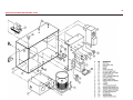
1
1
Magellan-2200 Model 2 Anesthesia Machine Operators Manual
CAUTION: Federal law restricts this device to be
used by or on the order of a physician.
Updated: 11.11.06
8005 Shannon Industrial Park Lane
Atchison, Kansas 66002
Tel: 913 874 2000
Fax: 913 874 2005
[email protected]
2
TABLE OF CONTENTS
PAGE
SUBJECT
• General Description
3
• Definition of Statements
3
• General Warnings
3
• Machine Specifications
3
• Functional and Operational Procedures
5
Assembly of Components
6
Pneupac® CompPAC™ Ventilator and Compressor
12
Pre-Use Checklist
28
Functional Operation of Controls and Accessories
31
Post-Use Checklist
36
• Cleaning, Disinfecting and Sterilization
37
• Minor Maintenance Recommendations
37
Tools Needed for Maintenance
37
• PROBLEM SOLVING GUIDE
38
• VACUUM MANIFOLD
38
• CYLINDER GAS DURATION FORMULA
39
• GAS FLOW DIAGRAMS
40
• ITEMS FURNISHED WITH EACH MACHINE AND PART NUMBERS
45
• ADDITIONAL ITEMS NEEDED FOR OPERATION AND MAINTENANCE
45
• BILL OF MATERIALS WITH PART NUMBERS
46
• EXPLODED DIAGRAMS OF MAJOR COMPONENTS
50
3
GENERAL DESCRIPTION
The Magellan-2200 Anesthesia Machine is compact robust and flexible, easy to transport
and was designed for military forward surgical teams, combat surgical hospitals, general
civilian hospitals, outpatient surgical centers, office-based anesthesia, military and civilian
veterinary medicine.
3. Gas Power Source - Ensure that adequate Oxygen and Compressed Medical Air pressure
and volumes are available before engaging the ventilator power toggle switch to ensure
proper operation of the ventilator.
MACHINE SPECIFICATIONS
DIMENSIONS
The Magellan-2200 is completely pneumatically powered and is designed to be used with
any complete or simple patient monitoring system that the operator prefers to use or has
on hand.
Height
23 inches
Depth
23 inches
The Magellan-2200 may be mounted on its custom-made carrying case, a mobile trolley
especially designed for the unit, other mobile carts or on a tabletop as the operator prefers.
Width
17 inches
Factory Quality Assurance Testing
Weight
• Free-Standing
• Enclosed in Carrying Case
45 lbs
130 lbs
Each Magellan-2200 is tested several times during the manufacturing process. Final testing
and calibration of components and the completed machine are recorded and a final
functional test copy is included in the shipment from the factory to the initial customer.
Machine Materials
Aluminum, brass and plastic
DEFINITION OF STATEMENTS
Carrying Case Materials
Plastic, military grade
The following terminology and statements are important for the operator to understand
before proceeding with the manual or operation of the Magellan-2200:
Operating Temperature Range
35 degrees F to 110 degrees F
Required Gas Supply Sources
WARNINGS: indicate a possibility of injury to the operator or others
CAUTIONS: indicate a possibility of damage to the equipment
• O2 Main and Cylinders
• Air and/or Air Compressor
• Oxygen Concentrator
38 to 70 psi (50 psi is optimal)
38 to 70 psi (50 psi is optimal)
3 to 10 psi (For O2 Flowmeter only)
NOTES: indicate points of interest for proper operation of the equipment
Flowmeter Fresh Gas Flow
1 to above 20 lpm (each flowmeter)
General Warnings:
Oxygen Flush Valve
Recessed, self-closing, push-button, color coded and
labeled, provides 45-55 lpm constant flow, while
push-button is depressed; may not be used with
O2 concentrator as O2 power source
CO2 Absorber System
King Systems KAB-9 (re-fillable) or KAB-1
(pre-filled/disposable)
CO2 Absorber Canister Capacity
400 grams soda lime
Directional Valves
Built in the CO2 Absorber
1. Patients requiring life-support equipment should be under the constant surveillance of
competent medical practitioners. There is always the possibility of machine and alarm
failure and some malfunctions require immediate, corrective action.
2. Vaporizer-Tilting the vaporizer past 45 degrees with liquid agent in the chamber can
result in patient injury or death. If tilted past 45degrees, empty the chamber, fully open the
percent control, then flush the vaporizer with Oxygen from the Oxygen flowmeter set to
5 lpm for 10 minutes.
4
Bag-Ventilator Switch/PRV
and Scavenger Outlet Port
Hand-operated selector switch and rotating knob for PRV
and scavenging outlet
Bellows
Latex free, upward inflating, range from 0 to 1.6 L
Bellows Pressure Relief
Pre-set at 60 cmH2O
Common Gas Outlet
Tubing Circuit
Vaporizer
Penlon SigmaDelta Series, bolt (cage) mounted,
temperature compensated, very low maintenance
Airway Pressure Gauge
Dual scaled in cmH2O and mmHg, located on front
panel of ventilator
Quick-connect, size indexed
Pressure Gauge Tubing
King Systems F-360-61 or any standard anesthesia
circle circuit
May be attached to bag/vent switch arm or to a point
within the patient breathing circuit (operators choice).
Mechanical Ventilator
Pneumatically powered, time cycled, volume constant,
flow variable
• Ventilator Pressure Relief
Pre-set to maximum of 60 cmH2O located in main vent box
• Minute Volume Range
6 to 14 L
• Insp. Flow Range
10 to 40 L/min
• Frequency breaths per minute 10 to 30
• Exp. Ratio-Fixed
1:1.8 nominal
Gas Pressure Hoses
DISS and thread indexed, female connectors at both ends
Gas Inlet Manifold
DISS and thread indexed, male connectors with one-way valves
Gas Inlet Manifold Filters
Located behind Manifold Air and O2 inlet male connectors
Gas Inlet Pressure Regulators
• Main supply cylinder
• Safety back up cylinder
DISS/thread indexed for O2
Pin-indexed, yoke mounted for "D" and "E" cylinders for O2
Ventilator Gas Power
Requirements
40 to 70 psi, 50 psi optimal
Use toggle switch to select gas source
Oxygen and Air Supply Gauges
0-3000 psi range, color coded and clearly labeled
Waste Gas Scavenger
Positive and negative relief valves, 1 L reservoir bag,
vacuum control knob
Pneumatically actuated when O2 supply falls below 30 psi
Pneumatically actuated when O2 supply falls below 1 psi
9-volt battery located in body of alarm box
Labeled toggle switch located on body of alarm box
Total Machine Gas Leakage
@ 30 cmH2O
@ 80 cmH2O
-0- ml/Min
-0- ml/min
Internal System Compliance
@ 20 cmH2O
@ 40 cmH2O
1.1 ml/cmH2O
1.3 ml/cmH2O
Internal System Resistance
@ 1.0 L/sec gas flow
@ 0.5 L/sec gas flow
4.11 cmH2O
1.80 cmH2O
APL Valve Pressure Drop
@ 3.0 L/min gas flow
@ 30 L/min gas flow
0.12 cmH2O
1.03 cmH2O
+ 160°F
- 30°F
Allow unit to warm to normal
OR temp for 1hour
Oxygen Supply Alarms
• Main and safety back-up
• O2 Concentrator
• Alarm power source
• Alarm on/off
Air and O2 Flowmeters
Calibrated and scaled 0-10 lpm, color coded, O2 flowmeter
has a fluted control knob for easy identification by touch,
alone
Oxygen Concentrator
To power O2 flowmeter only
Air Compressor
May be used to power ventilator and air flowmeter
Oxygen Analyzer/Monitor
OM-25-ME (or equivalent) Galvanic cell sensor, life
expectancy 2 years under normal conditions
Oxygen Analyzer Power Source
2 each AA batteries, life expectancy approx. 3000 use hours
Storage
• Indoor
• Outdoor
5
FUNCTIONAL AND OPERATIONAL PROCEDURES
The following procedures should be performed between the time the Magellan-2200 is
assembled for use, actually used and post-use, to ensure proper assembly of components
and operation.
1. Removal and Mounting of Machine
Turn on side, open, remove lid
2. Remove machine; Turn open box so that
wheels are down.
3. Review parts in lid of ventilator box.
4. Positioning of parts in lid of ventilator box.
5. Mount anesthesia machine to top of
box, securing with mounting screws.
6. Reattach lid of box to front of box with
machine mounted.
7. Attach small O2 cylinder mount to box back.
8. O2 cylinder mount completely attached.
6
ASSEMBLY OF COMPONENTS FOR USE OF THE MACHINE
BACK OF MACHINE
3. Oxygen Hose: Main O2 Supply:
Attach one end of the 15-foot green O2 high pressure hose to the top left O2 inlet
connector on the Gas Manifold and the opposite end to the O2 source (either an O2
Cylinder or O2 Wall outlet.)
1. Pressure Reducing Regulator:
Attach yoke-type pressure reducing regulator to the "D" or "E" Oxygen cylinder to be used
for safety back-up purposes.
2. Oxygen Hose:
Attach one end of the 24-inch green O2 high pressure hose to the outlet port of the
pressure reducing regulator and the opposite end to the left-side of the Gas Manifold.
4. Oxygen Concentrator in Lieu of Main O2 Source:
If an O2 Concentrator is to be used instead of cylinder or wall O2 sources, the tubing from
the O2 concentrator should be connected to the specially labeled (O2 concentrator only)
inlet nipple located above and to the right side of the Gas Manifold.
7
5. Water Trap:
Attach the Water Trap to the Air inlet port on the GasManifold
CAUTION: Do not attach the water trap to the outlet port of the Air Compressor as water may
condense enroute to the anesthesia machine and cause possible malfunction of some of the
components.
6. Air Hose:
Attach one end of the 15' yellow Air high-pressure hose to the inlet port of the Water Trap.
Attach the opposite end of the high pressure hose to the air compressor outlet port or to
other Air sources (wall or cylinder)
7. Waste Gas Scavenger Tubing Connection:
1. Attach the waste gas scavenger to the upper right hand side of the back frame, using the
Velcro strip or keyhole mounting, then attach the reservoir bag to bottom port of the
scavenger. Attach suction source tubing to the inlet port of scavenger control knob port.
NOTE: In military field conditions the reservoir bag to the bottom port of the scavenger
may be replaced with a large bore hose to possibly evacuate waste anesthetic out of the
work area.
.
WARNING: Scavenger system should always be mounted in order to keep debris from
entering the bellows outlet port.
1. Attach one end of the first scavenger tubing to the scavenger outlet port of the B/V
Switch labeled "to scavenger" and the opposite end to the "TEE" connector.
2. Attach one scavenger tubing, with the 19mm purple connector to the center port located
on the base of the Bellows, and attach the other end to the "TEE" connector.
3. Attach the final scavenger tubing to the top of the Waste Gas Scavenger and the other
end to the "TEE" connector.
VENTILATOR SIDE OF MACHINE
1. CO2 Absorber Support Arm:
Attach the CO2 Absorber Support Arm to the Main body of the machine by inserting the two
pins of the Arm into the two holes provided-then screw in the knob-screw from the back side
of the frame to secure the Arm. Ensure that the stem of the Arm is pointed upwards.
8
2. Bag-Vent Switch Assembly Arm:
Attach the Bag/Vent Switch Assembly Arm to the top of the machine, using the dowel pin guide
located under the top of the machine and insert the B/V Switch hole provided for the dowel pin.
Secure the B/V Switch by inserting the knob-screw through the top of the machine.
9
3. Reservoir Bag:
Attach the Reservoir bag to the chrome inlet port connector
located on the bottom of the B/V Switch Arm.
4. Airway Pressure Gauge Tubing:
Attach the Airway Pressure Gauge Tubing connector to the bottom of the B/V Switch Arm.
5. Gas Flow Tubing:
Attach the semi-clear tubing from the Common Gas Outlet to the inlet connector of the
CO2 absorber.
NOTE: If the clear plastic connector (supplied with the CO2 canister is not available, the
semi-clear tubing may be directly attached to the inlet port nipple of the CO2 canister.
10
6. CO2 Absorber Canister:
Attach the CO2 Absorber Canister to the Absorber Support Arm.
10. Patient Tubing Circuit:
Attach the preferred Patient Tubing Circuit to the CO2 Absorber inlet and outlet
connecting points.
BAG AND VENT ARM TUBING
7. Attach the RED labeled tubing to the outlet of the ventilator as shown on the label. Then
attach the other end of the tubing to the ventilator inlet port of the bellows (far right port)
using the 17mm connector.
8. Attach the GREEN labeled tubing to the brass outlet port of the B/V Switch and the
opposite end to the bottom right connector ("L" shaped) located on the bottom-right
position of the CO2Absorber.
9. Attach the BLUE labeled tubing to the right side inlet port of the
Bellows (labeled blue) and the opposite end to the lower outlet port of the
B/V Switch (labeled "To Bellows").
NOTE: Any patient tubing circuit approved for use with an anesthesia machine may be
used. The factory supplies a King Systems F-360-61 circuit with each machine as it is initially
shipped.
11
FRONT AND TOP OF ANESTHESIA MACHINE
OXYGEN MONITOR ATTACHMENTS
3. Attach the O2 monitor O2 sensor into the blue O2 sensor bracket.
1. Attach the O2 monitor-mounting bracket to the right side support post. Insert the monitor
into the slide bracket.
CAUTION: Insure that the O2 monitor sensor is mounted into the sensor bracket facing upward
for best performance and to keep any humidity from accumulating around the sensor.
2. Attach the blue O2 monitor sensor bracket into the Inspiratory outlet located on the
left-hand side of the front of the CO2 absorber.
12
PNEUPAC® COMPPAC™ VENTILATOR AND COMPRESSOR USER’S INFORMATION
504-2107 3
Table of Contents
SECTION 1
(a) Summary Statement
(b) WARNINGS AND CAUTIONS
(i)WARNINGS
(ii) CAUTIONS
Page
13
13
14
14
15
SECTION 2: GENERAL INFORMATION
(a) Intended Use
(b) Contraindications – None Known.
(c) General Description
(d) Ventilator and Compressor Controls, Indicators and Connections (Figure 1)
(e) Accessories
16
16
16
16
16
20
SECTION 3: SET-UP, USE and FUNCTIONAL CHECK
(a) Set-Up
(i) comppac Ventilator
(b) Functional Check
22
22
22
24
SECTION 4: OPERATION
(a) User’s Skill
(b) Setting of the Ventilator
(i) General
(ii) Ventilating the Patient
27
27
27
27
27
SECTION 5: CARE, CLEANING and STERILIZATION
(a) Care
(b) Battery Care
(c) Cleaning
(d) Sterilization
(e) Assembly and Function Testing
(f ) Decontamination
28
28
28
28
28
28
28
SECTION 6: MAINTENANCE
(a) General
(b) Performance Checking
(c) Service
(d) Compressor Reservoir Maintenance
(e) Storage
29
29
29
29
29
30
Smiths Medical International Ltd. reserves the right to make changes, without notice, which may affect the
information contained in this manual. Trademarks: The names “Pneupac”, “comppac”, “comppac” and
“Smiths” are trademarks of Smith’s family of companies.
13
SECTION 1
(a) Summary Statement
The comppac OEM ventilator is a gas powered automatic ventilator intended to provide
ventilation during anesthesia, in a military field hospital, to adult and paediatric patients
greater than 20 kg (44 lb). The comppac OEM ventilator comprises two separate cases, one
case containing the ventilator that is fixed into an Oceanic Magellan 2200 portable
anaesthetic machine and the other case containing the compressor which is free standing
and provides air for both the ventilator and anaesthetic machine flowmeter.
The primary role of the comppac OEM ventilator is to provide patient ventilation when
fitted to the Oceanic Magellan 2200 Portable Anaesthesia Machine. It can be powered by
compressor oxygen, compressed air or by an electrically operated compressor. The
ventilator can be driven in various ways:
i) Oxygen from a nominal 60psi supply which can be powered by;
• Regulated compressed cylinder, or
• Wall-mounted outlets
ii) Air from a nominal 60psi supply which can be powered by:
• Regulated compressed cylinder, or
• Wall-mounted outlets
iii) Internal compressor providing compressed, fresh air. This can be powered by:
• internal 24V battery, or
• external 24/28V d.c. supply, or
• external 115V a.c. supply (via PS11 power supply), or
• external 240V a.c. supply (via PS11 power supply)
or PS 12
The comppac OEM ventilator comprises of the following standard kit parts:
• Ventilator Module: Part No - 510A3053 (1)
• Compressor Module: Part No – 510A3060 (2)
• Rubber Boot: Part No – 510A2271 (3)
• NBC Filter: Part No – W7265 (4)
• Hose MA4 DISS to DISS: Part No – 500A4888 (5)
• 24/28 volt open-ended Vehicle Supply lead to comppac: Part No – 510A3096 (6)
• comppac ventilator / compressor User Manual: Part No – 504-2107 (Not shown)
• Water trap Assembly: Part No – 510A3105 (7)
• Interconnection cable: Part No – W288-001 (8)
• Reservoir Cover Spares: Part No – 510A2956 (Not shown)
• Sensing line: Part No – 510A3107 (9)
• NiCad Battery: Part No – 510-A1490 (10)
• Microbiological Filter: Part No – W8860 (11)
2
Graphical representation of electrical power source inputs, their relevant interfaces/
devices and outputs.
To run the comppac:
2
PS 12
— Charging While Operating
entilator
V
Figure 1: CompPac OEM System
14
The following labels are fitted on the ventilator module:
• Ventilator Panel Label: Part No – 504-351
• Patient monitoring port identification label: Part No – 504-353A
• Gas supply port identification label: Part No – 504-353B
• Interconnection port identification label: Part No – 504-353C
• Federal law label: Part No 504-1166NUS
• Alarm Bezel Label (set of 2): Part No – 504-222
And the following fitted labels on the compressor module:
• Compressor panel label: Part No - 504-352
• Battery fitting and removal instruction Label: Part No – 504-223
WARNING: Failure to read this user’s handbook before first use of this device may
result in death or serious injury.
WARNING: To avoid harm to the patient, pre-use checks must be performed in
accordance with section 4 of this manual before each use.
WARNING: Always ensure that an alternative means of ventilation is available in the
event of ventilator failure or malfunction.
All operators should receive a full and proper initial and ‘refresher’ instruction from a
qualified person, both on resuscitation and on detailed use of the equipment in the
particular situations in which it might be employed.
WARNING: To avoid harm to the patient, this equipment should only be used by
personnel trained in the use of automatic ventilation.
Information given in this manual beyond the basic operation of the comppac ventilator is
only intended as a guide to supplement proper training and to indicate the specific
operational requirements of the comppac. The comppac ventilator is intended for use in
anesthesia by users who are appropriately trained and where the patient is being
constantly monitored.
WARNING: Failure to constantly monitor the patient whilst using this equipment,
may lead to death or serious injury.
Although use of this ventilator outside the environmental conditions specified in this
Manual will not directly lead to a safety hazard the performance will become increasingly
uncertain as the conditions become more extreme. Therefore the operator must exercise
constant patient vigilance under these conditions.
WARNING: Blood gas levels must be monitored independently, correct operation of
the ventilator will not necessarily achieve the required blood gas levels. Also, when
used at moderate altitude, it is essential that the user closely monitors delivered
tidal volume, and measures end-tidal CO2 using suitable capnography.
(b) WARNINGS AND CAUTIONS
(i) WARNINGS
Warnings are given to make you aware of dangerous conditions, that could lead to death
or serious injury to the user or patient, that can occur if you do not obey all of the
instructions given in this manual.
The following Warnings highlight aspects of the use of the comppac ventilator that
require particular emphasis. The section of this manual referenced in each clause provides
the relevant context:
1.WARNING: Failure to read this user’s handbook before first use of this device may
result in death or serious injury (Section 1(a)).
2. WARNING: To avoid harm to the patient, pre-use checks must be performed in
accordance with section 4 of this manual before each use (Sections 1a) & 3b)).
3. WARNING: Always ensure that an alternative means of ventilation is available in
the event of ventilator failure or malfunction (Section 1a) & 4).
4. WARNING: To avoid harm to the patient, this equipment should only be used by
personnel trained in the use of automatic ventilation (Sections 1(a), 3(a), 4(a), &
4g)).
5. WARNING: Failure to constantly monitor the patient whilst using this equipment,
may lead to death or serious injury (Sections 1(a) & 4b)ii)).
6. WARNING: Blood gas levels must be monitored independently, correct operation
of the ventilator will not necessarily achieve the required blood gas levels. Also,
when used at moderate altitude, it is essential that the user closely monitors
delivered tidal volume, and measures end-tidal CO2 using suitable capnography
(Section 1(a)).
7. WARNING: To avoid the potential risk of explosion associated with re charging the
Lithium version of battery, ensure that only a Ni Cad battery (Part No: 510-A1490/
CE, NATO No: 6140-99-620-8057) is installed. UNDER NO CIRCUMSTANCES SHOULD
THE LITHIUM BATTERY (NATO No: 6135-99-840-0109), OR ANY OTHER PRIMARY
BATTERY, BE FITTED. (Sections 2c), 2d) #14, 2d #15, 2e) iii), 3a), & 5b)).
8. WARNING: To avoid malfunction of the ventilator when using the battery as a
power source, periodically check the battery to ensure that there is sufficient
charge to power the ventilator. The battery may be trickle or fast charged using
the PS11 power supply/ charger unit (see section 2e) iii), however, this should be
undertaken in advance of use and, where necessary (ie: battery does not retain its
charge), the battery may need replacing (Sections 2e ii) and 5b).
9. WARNING: To avoid the risk of fire or explosion or impaired ventilator
performance, always observe the correct polarity of the auxiliary supply. Ensure
the supply is a stable voltage from 23 to 30 volts capable of supplying 3 Amps (5
Amp surge on motor start) and does not contain excessive interference (Section
2e) iii).
10. WARNING: When in use in a contaminated atmosphere, to avoid the risk of harm
to the patient, the NBC filter must be fitted (Section 2e iv)).
15
11. WARNING: To avoid the risk of electric shock, when using the comppac ventilator
in conjunction with the Power Supply/ Charger, the Power Supply/ Charger
should be located outside the patient environment (ie: ≥ 1.5 Metres from the
patient) (Section 2d) #15 and 3a) ).
12. WARNING: Switching on the ventilator before the compressor reservoir pressure
reaches 50 psi as indicated on the anaesthetic machine air pressure gauge may
cause the gas failure indicator to malfunction. To avoid this always allow
compressor reservoir pressure to build up to 50 psi before switching on
ventilator (Section 3b) and 4).
13. WARNING: When running the ventilator from the compressor, rapid extreme
changes in temperature and humidity may cause the ventilator to malfunction
(Section 3b) and 4).
14. WARNING: Setting the anaesthetic machine air flowmeter above 2L/min may
cause an excessive drop in compressor reservoir pressure with a subsequent
drop in ventilation performance (Section 3b) and 4).
15. WARNING: Deviations noted at the functional check should be reported
immediately and the unit must be taken out of service to avoid the risk of death
or serious injury (Sections 3b)#9 & 6b).
16. WARNING: To avoid the risk of chemical / environmental hazards, disposal of a
contaminated/ used NBC filter must be in accordance with local regulations
(Section 3b #11).
17. WARNING: To avoid the risk of over inflation of the patient it is important for the
operator to constantly monitor the patient pressure manometer during manual
ventilation (Section 4).
18. WARNING: To avoid the risk of cross contamination all re usable components in
the patient circuit, that can come into contact with the patient or the patient’s
exhaled gas (Patient Valve and Patient Hoses) should be sterilized or disinfected
as per instructions detailed in Sections 5d) and 5e) of this user manual. The
sterilization process will also minimize the risk of contaminating the patient with
Legionella, which can found in some hospital hot water reservoirs.
19. WARNING: Failure to use approved circuits and accessories may lead to
unsatisfactory ventilator performance (Section 7).
20. WARNING: To avoid the risk of harm to the patient from an incorrectly set
ventilator, servicing or adjustment of this equipment should only be carried out
by competent personnel who have been trained by Smiths Medical International
Ltd. to carry out such work (Section 6c).
21. WARNING: Extreme environments may impair ventilator performance, operator
vigilance is required to monitor the patient.
22. WARNING: To avoid the risk of under inflation of the patient, it is important for
the operator to monitor tidal volumes. This is especially important iwth a
combination of ventilator minute volume settings of 12L and above, power
supply voltages below 24 Vdc and patients with low compliance lungs and
highly restrictive airways.
(ii) CAUTIONS
Cautions warn of dangerous conditions that can occur and cause damage to the
ventilator or its accessories, if you do not obey all of the instructions given in this manual:
1. CAUTION: It is recommended that the comppac ventilator is only used with a battery
installed, even if the ventilator is being powered by gas only, as the battery is used to
power the electronic alarm system. The ventilator will work without a battery or external
electrical supply, since it operates as a conventional gas powered device with the
patient protection devices and the high inflation pressure pneumatic alarm operating
normally. However, the user must be aware that in these circumstances, the electrically
operated alarms will NOT function. (Section 2e).
2. CAUTION: To avoid accidental disconnection of the power supply unit (PS11) when it is
connected to the comppac OEM unit, the power supply mains lead should always be
locked in position. (Section 2e).
3. CAUTION: Avoid fast charging batteries outside the temperature range of +10ºC to
+30ºC. The batteries will not accept a full charge outside this range and, in certain
circumstances, the capacity of the battery may be permanently impaired. At low
temperature, the electrolyte may be electrolysed, and small quantities of hydrogen
released, which in extreme circumstances present an explosive risk. (Section 2e).
4. CAUTION: The protective bung fitted to the NBC Filter should always be removed
before fitting it to the comppac ventilator (Sections 2e) & 3b) #11).
5. CAUTION: Excessive ingress of moisture could result in deterioration of internal
components, if the device is unlikely to be used regularly (ie more than once a week).
This could also result in the ventilator failing to start. To avoid this, ensure that the
comppac compressor unit is properly dried after each use. The comppac ventilator must
be dried internally as detailed in Section 5 a) iv), powered by the compressor alone (i.e.
delivering 21% oxygen) (Section 5ea).
SECTION 2: GENERAL INFORMATION
(a) Intended Use
The comppac OEM ventilator is a gas powered automatic ventilator intended to provide
ventilation during anesthesia, in a military field hospital, to adult and pediatric patients
greater than 20 kg (44lbs). The comppac OEM ventilator comprises two separate cases, one
case containing the ventilator that is fixed into an Oceanic Magellan 2200 portable
anaesthetic machine and the other case containing the compressor, which is free standing
and provides air for both the ventilator and anaesthetic machine flowmeter.
It has been designed to function using a NATO approved NBC filter (NATO No: 4240-21912-5397), and is therefore suitable for use in chemically laden environments that
are likely to be encountered on the battlefield. It can be operated from a range of power
sources to provide maximum flexibility of operation in remote areas, in military campaigns
and in disaster relief. It is suitable for ventilating adults and children (above 20 kg).
The comppac ventilator and associated equipment described in this manual conform to
ASTM F1101– 90 Standard specification for ventilators intended for use during anesthesia.
(b) Contraindications – None Known.
(c) General Description
The comppac COM OEM ventilator is gas powered and is housed in an enclosure designed
to fit into the Oceanic Magellan 2200 portable anesthesia machine. The separate
compressor housing is designed to accept the long endurance battery that is used to drive
a small compressor, which in turn provides compressed air, to power the ventilator and up
to 2 L/min for the anesthesia flow head fresh gas mix. All ambient air via the compressor
for the fresh gas mix from the anesthesia machine passes into the system through a
standard *NBC filter. About 1/3 of the volume is compressed to drive the ventilator before
expansion in an entrainmentmixing device, which entrains the other 2/3 by creating a
sub-atmospheric pressure. This entrained gas is not filtered through the NBC filter since the
ventilator gas is separated from patient gas by the anesthesia machine bellows.
The NiCad rechargeable battery specified for fitting inside the unit will provide
approximately 2 hours continuous ventilation (also dependent on the ventilator setting
during use). The compressor has an external straight bayonet push-pull type connection
on the front panel. This enables the system to be used for extended periods wherever a
24-28V d.c. supply is available. The power requirement is less than 50 watts. If the power
supply is connected to this socket, simultaneous trickle charging of internal battery will
occur whilst the ventilator is running.
WARNING: To avoid the potential risk of explosion associated with re charging the Lithium
version of battery, ensure that only a Ni Cad battery (Part No: 510-A1490/CE, NATO
No: 6140-99-620-8057) is installed. UNDER NO CIRCUMSTANCES SHOULD THE LITHIUM
BATTERY (NATO No: 6135-99-840-0109), OR ANY OTHER PRIMARY BATTERY, BE FITTED.
16
An input gas pipe is provided to allow the comppac ventilator to be connected to a 280 to
600 kPa gas supply from the Oceanic Magellan 2200 anesthesia machine so that it can be
operated independently of the compressor module. In this way, if oxygen or air cylinders
or liquidoxygen are available, this can be used to power the ventilator and the internal
battery can be conserved.
Calibrated controls for frequency and minute volume are provided to set the required
ventilation pattern. A fixed pressure relief device limits the peak inspiratory pressure and
provides a pneumatically operated audible high-pressure alarm. In addition an electronic
high-pressure alarm sounds if the inflation pressure exceeds 60 x100Pa (60 cm H2O).
There is negligible interdependence of these controls.
All controls and indicators are mounted on the front panel.
The layout is shown on Figure 1.
The electronic alarm unit not only gives warning of high inflation pressure but also of
patient circuit disconnection, failure to cycle and low voltage. It is powered from the
internal battery within the compressor module and will operate even if the battery power
is too low to operate the compressor. The interconnection cable must be connected
between the ventilator and the compressor in order for the electronic alarms to function.
There is no specific control switch on the alarm system. With the main battery and
interconnection cable in place it is energised automatically whenever the ventilator is
operated by switching the compressor on or by the application of gas pressure to the
auxiliary connection.
The alarm is turned off by removing the gas supply if an external source is being used or
by returning the compressor on - off switch to “OFF”.
The comppac ventilator module is connected to the Magellan 2200 bellows by means of a
corrugated hose and remote patient valve.
(d) Ventilator and Compressor Controls, Indicators and Connections (Figure 1)
1. Minute Volume Control (See Figure 1)
This calibrated rotary control knob gives continuous adjustment of the minute volume
delivered to the patient over the range 6 to 14 L/min.
2. Frequency Control (See Figure 1)
This rotary control knob gives continuous adjustment of frequency over the range 10 to
30 breaths per minute. The I:E ratio is nominally constant at 1:1.8 throughout the range of
frequency.
3. Patient monitoring port
The ventilator electronic alarm sensors and inflation pressure monitor connect to the
Magellan-2200 absorber manifold via the disposable filter and pipe assembly.
4. Pressure Relief Valve (See Figure 1)
The relief valve is connected inside the ventilator direcly into the ventilator circuit and
protects the patient from being delivered pressures in excess of the set level.
Note : Cycling pressure will be up to that set by the pressure relief valve.
17
upon airway restriction and/or lung compliance..
A fixed or adjustable relief valve set at 60 cm H2O may be fitted to the comppac ventilator.
If there is a battery in place, or an external electrical supply is connected, the independent
electronically operated high-pressure alarm will sound whenever the inflation pressure
exceeds 60 x100Pa (60 cm H2O). (See Section 2d #7)
The fixed relief valve can be unscrewed from the control panel but this is only advised for
cleaning and maintenance. Always use the wings on the body of the valve for tightening
and untightening.
Figure 1: Controls, Indicators and Connectors
5. Inflation Pressure Monitor (See Figure 1)
This pressure manometer displays the patient inflation pressure, as measured at the
ventilator outlet. It will give an accurate indication of the actual patient proximal inflation
pressure under all normal settings of the ventilator.
6. Supply Gas Failure (See Figure 1)
This mechanically operated visual alarm gives a warning that the supply gas has dropped
to a pressure at which the ventilator will no longer be operating to specification if
operating from a compressed gas supply. With low pressure it shows red, with adequate
pressure it shows white. Any visible red indicates that the supply should be changed. In
most cases the display will begin to oscillate from white to partial red as the supply
pressure falls to the low threshold level. The visual indication will be accompanied by an
electronically generated medium priority1* audible warning. In order to conserve the
battery, if this audible alarm is ignored for more than 60 seconds the alarm system will
ultimately switch itself off.
7. High Inflation Pressure Alarm (See Figure 1)
In addition to the audible alarm described in Section 2(d)#4 an independent
electronically generated audible and visual alarm is provided which operates when the
inflation pressure rises above 60 cm H2O irrespective of the setting or operation of the
relief valve. The electronic audible alarm only sounds after the alarm pressure has been
maintained for a period of one second in order to avoid the sounding of the alarm during
1* See section 10(e) for explanation of symbols and description of alarm priorities
18
transient pressure events. Initially the visual alarm only indicates each time the pressure exceeds the preset limit but if high pressure conditions persist the alarm latches to
give continuous flashing. Both audible and visual pressure alarms reset automatically
after 10 seconds when the condition is no longer present.
8. Cycle Indicator (See Figure 1)
During ventilation of the patient the inflation pressure is continuously monitored by a
positive pressure detector pre-set to 8 x100Pa (8 cm H2O). Each time the inflation pressure
rises through this set pressure level the green Cycle Indicator flashes for 1/10 second to
indicate to the user that, at the least, this inflation pressure is being achieved each cycle.
9. Low Inflation Pressure (Disconnect) Alarm (See Figure 1)
A medium priority†audible and visual alarm will operate to warn the user of a possible
disconnection in the ventilator breathing system, or that the ventilator is not cycling
correctly, if the inflation pressure generated by the ventilator does not rise through the
pre-set level of 8 x100Pa (8 cm H2O) at least once in any 10 second period. Both the
audible and visual alarms reset when the alarm condition no longer exists.
10. Silencing of Electronic Audible Alarms (See Figure 1)
A visual signal, consisting of an orange light flashing every 3 seconds, is used to indicate
when an electronically generated audible alarm has been silenced. For the first 60
seconds after switching on the ventilator all alarms except the supply gas failure alarm,
are automatically suspended although high priority visual alarms will still operate. Any
audible alarm can be silenced for a 60 second period, subsequently, by depressing
the silencing button but if a new alarm condition occurs during this period it will be
immediately annunciated.
If the silencing button is depressed pre-emptively, i.e. before any alarm sounds, then only
a new high priority alarm condition will cause an alarm to sound during the following
60 seconds.
11. Patient Outlet Connection (See Figure 1) – GAS OUTPUT
This outlet to the bellows from the ventilator is intended for the attachment of the patient
circuit supplied by Oceanic Medical products Inc. for the purpose.
12. Gas Input Connector (See Figure 1) – DRIVING GAS INPUT
This pipe is used to connect to the Oceanic Magellan 2200 anesthesia machine in order to
supply gas power to the comppac. This gas may be air or oxygen selected by the ventilator power switch on the Magellan 2200.
NOTE: The use of dry compressed gas is the preferred method of driving the comppac.
Any other gas source supplying the ventilator via the Magellan 2200 should be at 305-600
kPa (44-87 psi) and be capable of supplying 13 litres/min at this pressure.
13 Electrical Power level Indicator (See Figure 1)
A yellow visual indicator is used to indicate the state of the electrical power supplies to
the ventilator.
When the internal battery has been selected as the power source or when a gas supply
has been connected, the absence of any signal from this indicator, coupled with normal
operation by the alarm system indicators, confirms the internal battery is providing
adequate voltage. When the alarm system detects that the battery charge has dropped to
the level where approximately several minutes running time remains the yellow power
indicator will commence to flash once every 30 seconds to give advanced warning of
battery failure. As the charge reaches the point where it can no longer ensure full
performance of the ventilator the flashing rate of the power indicator will increase to
twice every second, accompanied by a medium priority* audible alarm. Although the
ventilator may continue to operate whilst the battery failure alarm is annunciating,
ventilator operation will become increasingly uncertain and damage may be caused to
the battery.
When an external electrical power source has been selected to power the ventilator and
the internal battery is installed and charged then, again, absence of any signal from the
power indicator, coupled with normal operation of the alarm system indicators, confirms
that both the external supply and internal battery are providing adequate voltage for
correct ventilation operation.
With an adequate external power supply and no internal battery, or a discharged battery,
the yellow power indicator will be constantly illuminated. A drop in voltage of the
external power supply will be indicated by the indicator flashing off once every 30
seconds. If the supply voltage drops to the level where correct ventilator operation cannot
be assured the power indicator flashes off twice a second and this is accompanied by a
medium priority* audible alarm.
If the compressor module is used to supply the compressed air, the supplied 1.5m hose
and water trap must be fitted between the compressor module and Magellan 2200 air
supply manifold and the interconnection cable fitted between the compressor module
and the ventilator module.
† See section 10(e) for explanation of symbols and description of alarm priorities.
* See section 10(e) for explanation of symbols and description of alarm priorities.
19
14. Cable disconnect alarm Test Switch (See Figure 1)
The Cable disconnect alarm Test switch is used to test the function of the cable disconnect
alarm which is housed within the compressor module. When the switch is depressed the
alarm sounder should sound continuously. The function of the electronic alarm system is
totally dependant upon correct connection of the interconnection cable between the
compressor module and the ventilator. For this reason the cable disconnect alarm should
sound when the cable connection has become compromised by accidental disconnection
or damage.
20. NBC Canister Adaptor (Not Shown)
This threaded adaptor is to a standard military specification for the connection of NBC
filters. The filter should always be screwed in fully so that it seals against the sealing
washer at the base of the adaptor thread.
The comppac should not be operated without a filter; other than its obvious need when
protecting the patient’s air supply; its presence ensures that dust and dirt do not enter the
patient circuit, valves and other internal sensitive areas.
15. Compressor ON / OFF (I / O) Switch (See Fig. 1)
When the ventilator is connected to the compressor module via the interconnection
cable, the compressor and electronic alarms are activated by switching this switch to the I
position. Please note that to prevent accidental switching, the switch has to be pulled out
before changing state from 0 (off) to I (on) and vice-versa.
Switching this switch to the 0 position stops the compressor. This will also stop the alarms
after 60 seconds providing no other gas source is switched to the ventilator.
16. Compressor power indicator LED‘s
External Power for Compressor and Battery Power for Compressor
When the compressor is switched on, the most appropriate power supply is selected
automatically depending on if the internal battery is fitted, if an external electrical supply
is fitted and the level of the electrical power available. The green LED is illuminated when
the system has automatically chosen an external electrical supply to run the compressor.
The yellow LED is illuminated when the system has automatically chosen the battery to
run the compressor.
Note: Power for the alarm system is taken from the battery by default unless no battery is
fitted or the battery is discharged.
17. Interconnection Port
The Interconnection port has a high density Female 15 pin D connector which will accept
a screened high performance SVGA monitor to PC cable. A box type bracket surrounds the
connector to provide support for the cable connector and provide protection to the
connection from excessive strain. The cable can be locked in place using the two screws
normally provided on the cable assembly.
18. Compressor Gas Output
The compressor gas output is fitted with a DISS Air type connector.
19. External Electrical Input Connector
The electrical input connector is a push – pull bayonet type. A red dot on the connector
must line up with the red dot on the cable plug and the connection is made by pushing
the cable plug into the connector. The plug will be locked in place until the collar of the
plug is pulled away from the connector.
Figure 2e —Battery Removed.Also refer to figure 6, installation is the reverse of removal
Figure 2 (See also Figure 4): Removal of the Battery (installation is reverse)
20
•
(e) Accessories
(i) Batteries
The comppac ventilator is designed to operate from the NiCad rechargeable version of a
widely stocked military 24V battery which was originally introduced to power the
“Clansman” communications pack; NATO No. 6140 - 99 - 620 - 8057. It is packaged in either
a plastic or metal casing but the comppac ventilator only accepts the plastic casing - there
are wider fixing lugs on the metal casing.
The Ni-Cad battery has an 85ºC internal thermal cut out.
WARNING: To avoid malfunction of the ventilator when using the battery as a power
source, periodically check the battery to ensure that there is sufficient charge to
power the ventilator. The battery using the power supply/charger unit (see section
2e) iii), however, this should be undertaken in advance of use and, where necessary
(ie: battery does not retain its charge), the battery may need replacing.
This battery needs to be recharged within a month before use. Battery life will depend on
ventilator settings, the table below shows typical battery duration for given settings:
The batteries are field exchangeable.
CAUTION: It is recommended that the comppac ventilator is only used with a battery
installed, even if the ventilator is being powered by gas only, as the battery is used to
power the electronic alarm system. The ventilator will work without a battery or external
electrical supply, since it operates as a conventional gas powered device with the patient
protection devices and the high inflation pressure pneumatic alarm operating normally.
However, the user must be aware that in these circumstances, the electrically operated
alarms will NOT function.
(ii) Power Supply/Charger
WARNING: To avoid the potential risk of explosion associated with re charging the
Lithium version of battery, ensure that only a Ni Cad battery (Part No: 510-A1490/CE,
NATO No: 6140-99-620-8057) is installed. UNDER NO CIRCUMSTANCES SHOULD THE
LITHIUM BATTERY (NATO No: 6135-99-840-0109), OR ANY OTHER PRIMARY
BATTERY BE FITTED.
The Main Power Supply/Charging Unit is specially designed for use with the comppac
ventilator. It will accept leads for connection to supplies of 200/250V 50Hz, 100/120V
60Hz or 24/28V d.c. respectively.
One of two different Power supply/Charging units may be supplied with the system depending upon
the date of manufacture. Earlier units may have a PS11 Power supply/Charging unit & later units will
have a PS12 Power supply/Charging unit. Each unit has a separate user manual:
•User Manual 504-2084NUS for the PS 11 (Part Number 510-2408) Power supply/Charging unit
•User Manual 504-2109 for the PS12 (Part Number 535A1034) Power supply/Charging unit
WARNING: To avoid the risk of fire or explosion or impaired ventilator performance,
always observe the correct polarity of the auxiliary supply. Ensure the supply is a
stable voltage of between 23 to 30 Volts capable of supplying 3 Amps (5 Amp surge
on motor start) and does not contain excessive interference.
Plug-in supply leads can be supplied to suit most mains outlet sockets used World-wide.
CAUTION: To avoid accidental disconnection of the power supply unit (PS11) when it is
connected to the comppac OEM unit, the mains lead should always be locked in position.
CAUTION: Avoid fast charging batteries outside the temperature range of +10ºC to +30ºC.
The batteries will not accept a full charge outside this range and, in certain circumstances,
the capacity of the battery may be permanently impaired. At low temperature, the electrolyte may be electrolysed, and small quantities of hydrogen liberated, which in extreme
circumstances present an explosive risk.
An auxiliary power supply lead, part number 510A2582, is available from Smiths Medical
International Ltd. to which the user can fit specific connectors to suit alternative 24/28V
d.c. power supplies. This lead has only a single circuit so simultaneous battery charging
will not occur with its use.
(iii) NBC Filter
WARNING: When in use in a contaminated atmosphere, to avoid the risk of harm
to
the patient, the NBC filter must be fitted.
The comppac ventilator is designed to accept any NBC filter with a NATO Stanag 4155
thread, in order to filter NBC contaminants from gas being drawn from the atmosphere for
supply to the patient. The selection and usage of a suitable filter for a particular
environment must be the judgement of a person trained in the use of such a filter but, in
principle, the criteria for selection, use and replacement will be identical to those which
would be appropriate to protect the spontaneous breathing of the rescuer. Smiths Medical International Ltd. can supply Avon L12A1 NBC Filter Canisters which are registered as
NATO No. 4240 – 99 – 132 – 0941.
21
CAUTION: The protective bung fitted to the NBC Filter should always be removed before
fitting it to the comppac ventilator.
For use in non-NBC environments it is recommended that the Avon L12A1 filter is always
used to act as a dust/particle filter. It will also act as a silencer. For non-NBC use the filter
only need be replaced at service intervals, and then only if it has been in normal emergency use.
(iv) Drive Gas Supply Hose
As standard Air Gas Supply Hose is provided in order to supply the anaesthetic machine
and ventilator with compressed air from the compressor. This hose has a DISS Air
connector on either end.
22
SECTION 3: SET-UP, USE and FUNCTIONAL CHECK
(a) Set Up
(i) comppac Ventilator
Unpack the comppac ventilator and its accessories and check all items against the
contents checklist. If any items are missing or incorrect, or have become damaged, notify
your supplier immediately.
WARNING: To avoid the risk of electric shock, when using the comppac ventilator in
conjunction with the PS11 Power Supply/ Charger, the PS11 should be located
outside the patient environment (ie: ≥1.5 Metres from the patient).
WARNING: To avoid harm to the patient, this equipment should only be used by
personnel trained in the use of automatic ventilation.
If a new NiCad battery is supplied it will need to be charged initially for 14 hours using the
PS11 Mains Power Supply with the recharging lead connected to the battery terminals by
means of the dedicated Charger to Battery recharging lead Pt. No: 510A2422.
WARNING: To avoid the potential risk of explosion associated with recharging the
Lithium version of battery, ensure that only a Ni Cad battery (Part No: 510-A1490/CE,
NATO No: 6140-99-620-8057) is installed. UNDER NO CIRCUMSTANCES SHOULD THE
LITHIUM BATTERY (NATO No: 6135-99-840-0109), OR ANY OTHER PRIMARY
BATTERY BE FITTED.
After charging the battery install in accordance with the instructions shown on the upper
face of the rubber boot, when removed from the comppac which are reproduced in Fig. 4.
Fit an NBC filter canister to the compressor by means of the specially threaded adapter in
the recess of the rear face. Screw it in fully until sealing contact is made with the sealing
washer at the internal base of the adapter.
The anaesthetic machine bellows unit can be screwed to the top of the ventilator
enclosure using the four screws provided with the bellows unit without removing the lid
from the ventilator enclosure. The top lid of the ventilator enclosure is fitted with clinch
nuts to accept the bellows unit screws.
The ventilator and bellows unit should be fitted into place on the Anaesthetic machine
frame and secured with a single countersunk screw through the bottom plate of the
machine frame and two screws through the back plate. Before securing the ventilator in
place, connect the gas supply pipe to the ventilator supply port on the anaesthetic
machine.
Fit an in-line biological filter to the patient monitoring port luer lock connector and fit the
sensing line assembly between the filter and the anaesthetic machine absorber manifold.
Interconnect the compressor to the ventilator as follows:
Fit one end of the interconnection cable into the strain relief bracket on the compressor
frontpanel to mate with the interconnection port. Check for orientation of the D shape
connector. Orientation guidance is provided by the interconnection port label. Screw in
the screws on the cable to make connection secure. Fit the other end of the
interconnection cable into the strain relief bracket on the rear of the ventilator to mate
with the interconnection port. Again, check for orientation by referring to label. Screw in
the screws on the cable to make connection secure.
23
MAGELLAN-2200 MODEL 2 MACHINE, AIR COMPRESSOR AND POWER SUPPLY – BACK VIEW
24
3. Set the ventilator controls as follows
a. Compressor power switch:
Off
b. Frequency:
13 b/min (detent position)
c. Minute Volume
12 L/min
WARNING: Setting the anaesthetic machine air flowmeter above 2L/min may
cause an excessive drop in compressor reservoir pressure with a subsequent drop
ventilation performance.
If using the compressor to provide the air gas power to the anaesthetic machine and
ventilator fit the 2m gas supply hose between the compressor and the anaesthetic
machine inlet manifold.
Connect the ventilator to the bellows unit using the red colored hose supplied with the
anaesthetic machine, the patient valve and 22 mm female to 15 mm male taper adaptor
supplied with the compPAC ventilator.
Note: A 90º patient 22mm male/female elbow connector may be fitted between
the ventilator output port and the hose for ease of use.
NOTE: If the ventilator output hose is incorrectly, connected to the ventilator, it will not
deliver tidal volumes and the alarm may not sound during the functional occlusion test
(See Section 3(b), 4(b)(ii) and 4(g)(iii) 5).
(b) Functional Check
WARNING: To avoid harm to the patient, pre-use checks must be performed
in
accordance with section 4 of this manual before each use.
WARNING: Switching on the ventilator before the compressor reservoir pressure
reaches 50 psi as indicated on the anaesthetic machine air pressure gauge may
cause the gas failure indicator to malfunction. To avoid this always allow compressor
reservoir pressure to build up to 50 psi before switching on ventilator.
WARNING: When running the ventilator from the compressor, rapid extreme
changes in temperature & humidity may cause the ventilator to malfunction.
The following procedure should be followed when first setting up the ventilator to check
that it has been assembled correctly and is operating safely. It should be repeated
periodically as specified under ‘Maintenance’.
1. Set up the anaesthetic machine in accordance with the Oceanic Magellan 2200
user manual. Connect a test lung or adult re-breathing bag to the patient connection
port.
2. Install and set up the ventilator as in section 3 (a) with a fully charged battery
installed in compressor.
4. Set the Anaesthetic machine as follows:
a. Air flowmeter:
Closed
b. Ventilator power switch:
Off
c. PRV valve:
Closed
5. Switch on the compressor using the switch of the front of the ventilator and
the ventilator alarms and compressor should start in the following sequence:
a. The cable disconnect/battery back up sounder located in the compressor
should beep once
b. The ventilator alarm LED‘s should illuminate in a clockwise sequence starting from
the low power LED. The disconnect LED will not illuminate during this sequence with the ventilator
switch set to ‘Off’. The illumination of LED’s will be followed by a single beeo of the cable disconnect
sounder.
c. The battery power for compressor LED should illuminate at the same time.
d. The compressor motor should start and run at high speed as long as the compressor
reservoir is below 44psi. If the reservoir presser is above 44psi, the compressor will
not re-start until the pressure has dropped to 44psi.
e. The compressor motor should start and run at high speed.
f. The disconnect LED and the silence LED should both flash initially. The silence LED
should stop flahing after one minute of operation.
6. Adjust the anaesthetic machine air flowmeter to a flow of 2L/min and allow the bellows
to fill-up fully. The compressor motor may slow down during filling the bellows indicated by a change in motor sound but this is normal.
7. The sounder in the compressor should beep every 15 seconds to indicate that the
compressor is running on back up battery power.
8. Push the test cable disconnect alarm button. While the button is depressed a continuous alarm should sound. This tests the function of the cable disconnect alarm.
9. When the bellows have been fully filled and the air pressure is above 50 psi, switch on
the ventilator by switching the anaesthetic machine ventilator power switch to “Air”.
10. The ventilator should cycle and power the bellows with a breath of approximately
900 mls. The green cycle LED should illuminate every breath providing the peak
proximal pressure is above10 cm H2O. Check over several breaths.
11. Disconnect the patient port from the re-breathing bag or test lung and block the
patient port. The relief valve alarm should operate and sound during the inspiration
cycle. The manometer should give a reading of 60 cm H2O This may be accompanied
by the ventilator high pressure LED flashing and alarm sounding.
12. Unblock the patient port & the bellows should be driven down to completely empty.
Again the relief valve alarm should operate and sound during the inspiration cycle. This
should be accompanied by the ventilator disconnect LED flashing and alarm sounding.
13. Switch off the compressor. The compressor should stop but the ventilator alarms
should carry on functioning for 60 seconds before shutting down.
NOTE: Short runs using the comppac compressor should be kept to a minimum in order
to minimize the requirement to dry the unit after use.
Finally, set the controls as specified in step 1 so the ventilator is left set for emergency use.
WARNING: Deviations noted at functional check should be reported immediately to
the manufacturer. and the unit must be taken out of service to avoid the risk of
death or serious injury.
14. Battery Replacement. If the battery needs replacing follow the instructions shown
on label Part Number 504-223, located on the inside face of the rubber boot,
which is reproduced in Figure 4 on next page.
15. NBC Filter Replacement
WARNING: To avoid the risk of chemical / environmental hazards, disposal of
a contaminated /used NBC filter must be in accordance with local regulations.
CAUTION: The protective bung fitted to the NBC Filter should always be removed
before fitting it to the comppac ventilator.
The ventilator should always be run with a NBC filter in place as this reduces the operating
noise as well as filtering the air entering the compressor. Other than the protection
provided to the patient’s air supply, the filter also prevents ingress of dust and dirt into the
ventilator circuit, which could cause deterioration of ventilator performance.
I
25
26
SECTION 4: OPERATION
WARNING: To avoid the risk of over inflation of the patient it is important for the
operator to constantly monitor the patient pressure manometer during manual
ventilation.
WARNING: Always ensure that an alternative means of ventilation is available in the
event of ventilator failure or malfunction.
(a) User’s Skill
The comppac ventilator is designed to be used by medically qualified personnel.
All potential users should familiarise themselves with the machine and its operation to
enable them to use it effectively. They should study the contents of this manual to the
extent required by their training.
WARNING: To avoid harm to the patient, this equipment should only be used by
personnel trained in the use of automatic ventilation.
(b) Setting of the Ventilator
(i) General
The ventilator should be left with the controls set in the position specified in the
functional check (Section 3(b)1) to enable it to be brought into use with a minimum of
re-adjustment.
Where the comppac ventilator is likely to be used away from gas sources it should be
stored with a fully charged known good battery and/or connection leads for use with an
outside power source.
(ii) Ventilating the Patient (Pre-Use Checks)
WARNING: Switching on the ventilator before the compressor reservoir pressure
reaches 50 psi as indicated on the anaesthetic machine air pressure gauge may
cause the gas failure indicator to malfunction. To avoid this always allow compressor
reservoir pressure to build up to 50 psi before switching on ventilator.
WARNING: When running the ventilator from the compressor, rapid extreme changes
in temperature & humidity may cause the ventilator to malfunction.
1. Set up the anaesthetic machine in accordance with the Oceanic Magellan 2200 user
manual. Connect a test lung or adult re-breathing bag to the patient connection port.
2. Ensure that the ventilator is installed and set up as in Section 3(a) with a fully
charged battery installed in compressor.
3. Set the ventilator controls as follows: the Minute Volume, Frequency, Tidal Volume
Conversion table will assist the operator in selecting the appropirate intial control
setting.
a. Compressor power switch:
Off
b. Frequency:
To suit patient
c. Minute volume:
To suit patient
WARNING: Setting the anaesthetic machine air flowmeter above 2L/min may cause
an excessive drop in compressor reservoir pressure with a subsequent drop
ventilation performance.
4. Set the anaesthetic machine as follows:
a. Air flowmeter:
Closed
b. Ventilator power switch:
Off
c. PRV valve:
Closed
5. Where a suitable gas source is available connect the gas supply hose between the
anaesthetic machine and the gas supply. Turn on the supply (if relevant).
6. Adjust the anaesthetic machine flowmeters to provide fresh gas of approx 5L/min and
allow the bellows to fill up fully.
7. Push the test cable disconnect alarm button. While the button is depressed a
continuous alarm should sound. This tests the function of the cable disconnect alarm.
8. When the bellows have been fully filled and the gas pressure to drive the ventilator is
above 50 psi, switch on the ventilator by selecting Air or oxygen as appropriate with the
ventilator power switch on the anaesthetic machine.
9. The ventilator alarms should start in the following sequence:
a. The ventilator alarm LED‘s should illuminate in a clockwise sequence starting from
the low power LED. A single burst of the ventilator high priority audible alarm is given
at the same time.
b. The silence LED should flash for one minute of operation. This allows for possible
disconnection during setting up.
c. Set the ventilation parameters to suit the patient.
10. The ventilator should cycle and power the bellows. The tidal volume being dependant
upon the ventilator settings. The green cycle LED should illuminate every breath
providing the peak proximal pressure is above 10 cm H2O.
27
11. If the airway is very restrictive and or the lung is very stiff or the airway is blocked the
relief valve alarm should operate and sound during the inspiration cycle. The
manometer should give a reading of 60 cm H2O. This may be accompanied by the
ventilator high pressure LED flashing and alarm sounding.
12. If the patient hose becomes disconnected the bellows will be driven down to
completely empty. The relief valve alarm should operate and sound during the
inspiration cycle. This should be accompanied by the ventilator disconnect LED
flashing and alarm sounding.
13. When the ventilator is switched off, the ventilator alarms should carry on functioning
for 60 seconds before shutting down.
14. If the compressor is required to power the ventilator and provide air to the
anaesthetic machine follow the instructions given in the functional check.
WARNING: Failure to constantly monitor the patient whilst using this equipment,
may lead to death or serious injury.
The Inflation Pressure Monitor should be kept under constant observation so that adverse
ventilation conditions can be detected and corrected before the patient is put at risk.
If the pressure jumps excessively at the commencement of inspiration an airway
obstruction is indicated and this must be rectified. If the airway is clear the flow rate may
be too high and this is reduced by decreasing the minute volume setting.
Excessive pressure at the end of inspiration indicates a high tidal volume. This may be
reduced by either reducing the minute volume or increasing the frequency.
If the inflation pressure is too low, firstly check for leaks, secondly check the ventilation
parameters, thirdly, check the patient valve for proper functioning.
NOTE: At all times check the adequacy of the gas source or the power supply/battery as
indicated by the electrical power indicator.
28
SECTION 5: CARE, CLEANING AND STERILIZATION
(a) Care
The compPAC ventilator is chemically hardened and is designed to be decontaminated by
approved methods. The casing is completely sealed apart from the control panel and the
batter compartment, which are protected by heavy shrouding. The canister connector is
protected in use by the NBC canister.
(b) Battery Care
The NiCad battery recommended for use with the compPAC ventilator should be
periodically charged to ensure it remains at full capacity. The battery should be removed
for storage periods greater than one month. Charging of the battery can be carried out,
both inside and outside of thecompPAC, using a recommended charger.
For NBC decontamination, the rubber boot, the battery and the battery fixngs should be
completely removed (see Figure 2 on page 20.) The casing can then be decontaminated
using the shroudings to protect the panel and internal parts of the battery compartment.
Light contamination of the controls on the shrouded panel should be decontaminated by
a method suitable for insrumentation e.g. light dusting with Fullers Earth.
i. Carefully inspect the complete Ventilator and Compressor system and make note of
what actions should be taken. In particular check for damage to hoses, contamination of
any component, evidence of any part having been subjected to excessive force and
missing parts.
WARNING: To avoid the potential risk of explosion associated with re charging the Lithium
version of battery, ensure that only a Ni Cad battery (Part No: 510-A1490/CE, NATO No: 614099-620-8057) is installed. UNDER NO CIRCUMSTANCES SHOULD THE LITHIUM BATTERY (NATO
No: 6135-99-840-0109), OR ANY OTHER PRIMARYBATTERY, BE FITTED.
WARNING: To avoid malfunction of the ventilator when using the battery as a power source,
periodically check the battery to ensure that there is sufficient charge to power the ventilator.
The battery may be trickle or fast charged using the PS11 power supply/charger unit (see
section 2e) iii), however, this should be undertaken in advance of use and, where necessary
(ie: battery does not retain its charge), the battery may need replacing.
ii) Remove, discard and replace the in line microbiological filter.
CAUTION: Excessive ingress of moisture could result in deterioration of internal
components, if the device is unlikely to be used regularly (i.e. more than once a week). This
could also result in the ventilator failing to start. To avoid this, ensure that the comppac is
properly dried after each use. The comppac ventilator must be dried internally as detailed
below, powered by the compressor alone (i.e. delivering 21% oxygen).
iii) If ventilator has been running powered by the compressor and with no oxygen input,
humidity in the ambient air drawn in by the compressor may have condensed in parts of
the internal pneumatic circuit. The design of the ventilator is configured to minimize this
effect and to dissipate any excess water but some dampness may remain after the unit is
switched off. To avoid any internal deterioration due to this condensation, after each use
perform the following shutdown actions if the device is unlikely to be used more than
once a week. Run the compPAC powered only by the compressor (i.e. delivering 21%
oxygen), internally dry the comppac ventilator using the following procedure:
Pneumatic Circuit Drying Procedure
Connect the Oceanic Magellan 2200 anaesthetic machine to a source of dry oxygen, e.g.
cylinder or pipeline. Turn the supply on and set the ventilator to 30 breaths per minute
and 14 L/min volume. Run for 15-60 minutes, depending on the ambient humidity under
which the ventilator has been running. If a humidity meter is available place it in the
ventilator output connector and run the unit until a dew point of about the 0º C is
achieved.
Additional instructions for the maintenance (only applicable to suitably trained
personnel) of the compressor reservoir are detailed in section 6 (d).
iv) Reassemble the system and carry out the function check specified in Section 3.
v) Stow the system in a clean area, away from heat and intense light.
(c) Cleaning
(i) comppac ventilator and compressor modules – Each module should normally be
cleaned by means of a damp cloth. For obstinate marks a mild soap or non-abrasive
cleaner may be used. Wipe dry immediately with a soft clean cloth.
Do not attempt to sterilize the Control Module or to clean it by immersion in any fluid.
Do not allow any oil or grease to come into contact with the input and output fittings
because of the potential fire risk when oxygen is being used.
(ii) Hoses – The Gas Supply Hose may be cleaned in the same manner as the Control
Module taking the same care to keep free from grease.
The Patient Hose may be cleaned in the same manner as the Patient Valve parts. The In
Line Filter should be replaced after every use.
(ii) Control Module – This module may be wiped with a mild disinfectant in accordance
with the disinfectant manufacturer’s instructions but must not be immersed.
(d) Sterilization
No parts of the comppac Module come in contact with the casualty’s expired gases and
therefore this unit is not designed to be sterilized.
(e) Assembly and Function Testing
After cleaning or sterilization, parts must be carefully dried and then reassembled. Before
putting the system back into stores or service the functional check described in Section 3
should be carried out.
(f) Decontamination
WARNING: To prevent transmission of any contaminants to both user and patient after use in a
contaminated environment, be aware that the comppac outer case is NOT hermetically sealed
against ingress of gas or liquids. Decontamination, if necessary, should involve removal of the
module from its case by a suitably trained person.
29
For NBC decontamination, the rubber boot, the battery and the battery fixings should be
completely removed (see Figure 2 on page 20). The casing can then be decontaminated using the
shroudings to protect the panel and the internal parts of the battery compartment. Light contamination of the controls on the shrouded panel should be decontaminated by a method suitable for
instrumentation e.g. light dusting with Fullers Earth.
SECTION 6: MAINTENANCE
(a) General
If the comppac ventilator shows a malfunction during operation or testing or if its performance is measured to be outside the acceptable tolerance before re-calibration stated in the
specification during its performance checking, then the unit should be withdrawn from
operation and an appropriate service must be carried out.
Servicing or adjustment of the comppac ventilator should only be carried out by
competent personnel who have been trained for such work.
(d) Compressor Reservoir Maintenance
The comppac ventilator requires checking for calibration settings at least annually. Service is only
required if calibration needs to be restored, if component failure occurs or if damage is incurred.
It is recommended that maintenance of units in service is carried out at two levels. At the first level,
the procedure specified in section 3 (b) should be followed at regular intervals, typically once a
month, irrespective of use, and a record kept by the use of the log sheet at the back of this manual.
At the second level, the performance of the ventilator should be checked as specified in Section
6(b).
Before the unit is put into storage, it is recommended that it is run for about one hour on dry
bottled gas as detailed in Section 5 (a)(iv).
(b) Performance Checking
During routine calibration/servicing of the comppac ventilator, it is advisable to
also clean the Compressor Reservoir. The cleaning procedure detailed below may
also be performed if there is suspicion that reservoir may be dirty or wet.
To carry out cleaning of the resevoir, proceed as follows:1. Remove the rubber boot from the bottom of the comppac compressor.
2. Remove the battery in accordance with the instructions detailed inside the
rubber boot.
3. Remove the battery retaining jacket from the battery compartment by separating the velcro fastenings.
WARNING: Deviations noted at functional check should be reported immediately to Smiths
Medical International Ltd. and the unit must be taken out of service to avoid he risk of death
or serious injury.
4. Remove the reservoir access plate retaining screws and detach the access plate.
Performance checking of the comppac ventilator must be carried out with equipment calibrated to
ensure accuracy under the flow patterns generated by the machine. It should only be carried out
by suitably trained personnel. If suitable personnel or equipment are not available, it should be
checked by Smiths Medical International Ltd. as part of service contract or its authorised representative.
6. Wipe clean all the inside surfaces of the reservoir with an absorbent lint free
cloth.
Recommended performance checking procedures and suitable equipment are detailed in the
product maintenance manual, which is available to suitably trained personnel.
The frequency of performance checking should be determined by the user. Normally, this would
be not more often than once every 6 months but at least once every two years.
(c) Service
Information will be made available to suitably qualified personnel upon request.
WARNING: To avoid the risk of harm to the patient from an incorrectly set ventilator, servicing or adjustment of this equipment should only be carried out by competent personnel
who have been trained by Smiths Medical International Ltd. to carry out such work.
5. Drain out any excess residual moisture from the inside of the reservoir.
7. Carefully remove the rubber ‘O’ ring seal from the groove in the access plate.
8. Wipe clean the ‘O’ ring seal and all the surfaces of the access plate, including the
seal groove, with an absorbent lint free cloth.
9. Using a clean absorbent lint free cloth, apply a disinfectant such as Ethyl or Iso
Propyl Alcohol (70% to 90%) to the inside surfaces of the reservoir, the rubber
‘O’ring seal and the access plate and leave for a duration of at least 10 minutes.
10. Rinse off the disinfectant with sterile water and fully dry the inside of the reservoir, ‘O’ ring seal and access plate. This may be done with a lint free cloth or a
clean forced air supply.
Note: If no sterile water is available, use tap water, followed by alcohol and then
dried by means of forced air.
30
11. Inspect the rubber ‘O’ ring seal for any sign of damage or detioration. If it is in good condition
carefully place it into the groove of the access plate. If there is any doubt about the condition of the
rubber ‘O’ ring seal discard it and fit a replacement.
12. Re-fit the access plate to the comppac reservoir and securely tighten the 10 screws (supplied as
a kit Part No. 510A2956).
13. Perform a leak test and any rectification as follows:(i) Temporarily reconnect the battery or a suitable d.c. supply to the comppac compressor.
(ii) Set the controls to 6mV and 10 b/Min.
(iii) Switch on the comppac ventilator.
(iv) Apply soap solution around the access plate and to the screw heads to check for any air
leakage.
(v) If an air leak is detected, switch off the comppac ventilator, disconnect the power source and
remove the access cover.
(vi) Re-check the condition of the rubber ‘O’ ring seal, replace if necessary. Also check the reservoir
plate surface for any particles of matter or scratches which could prevent the ‘O’ ring seal sealing.
After any corrective action, repeat the steps (i) to (iv) above.
14. On successful completion of the Leak test, replace the battery retaining jacket, battery and
boot. Carry out the pre use checks as recommended in Section –3b ‘Functional Check’ of the user
manual 504-2107 before deploying the comppac ventilator.
(e) Storage
If the comppac ventilator is to be stored for prolonged periods, it should be located in a cool dry
place out of direct sunlight. Remove the internal battery prior to any prolonged periods of storage.
Prior to use, following any prolonged storage, ensure that the comppac ventilator has stabilised to
a temperature within its specified operating range (-10ºC to +40ºC).
31
PRE-USE CHECKLIST
Emergency Ventilation Equipment
1. Verify backup ventilation equipment is available and functioning. It is recommended that
a self-inflating bag/valve/mask device with the ability to provide high concentrations of O2
be immediately available.
High Pressure System
2. Check Oxygen Cylinder Supply
A. Open O2 cylinder and verify at least half full (approx. 1000 psi).
B. Close cylinder
3. Check Central Pipeline Supplies
A. Check that hoses are connected and pipeline gauges read approx. 50 psi.
Low Pressure System
4. Check Initial Status of Low Pressure System
A. Close flow control valves and turn vaporizer off.
B. Check fill level and tighten vaporizer filler cap.
5. Perform Leak Check of Machine Low Pressure System
A. Verify that the machine flow control valves are OFF.
B. Attach "Suction Bulb" to common gas outlet.
C. Squeeze bulb repeatedly until fully collapsed.
D. Verify bulb stays fully collapsed for at least 5 seconds.
E. Open vaporizer and repeat "C" and "D" above.
F. Remove suction bulb and reconnect fresh gas hose.
32
6. Turn on Ventilation/Ventilator Alarm
7. Test Flowmeters
A. Adjust flow of Oxygen and Air through their full range, checking for smooth operation of
floats and undamaged flowtubes.
Breathing System
9. Calibrate Oxygen Monitor
A. Ensure monitor reads 21% in room air.
B. Verify low oxygen alarm is enabled and functioning
C. Re-install sensor in circuit and flush breathing system with Oxygen.
D. Verify that monitor now reads greater than 90%.
Scavenging System
8.
A.
B.
C.
D.
E.
Adjust and Check Scavenging System
Attach hose from bag-vent switch scavenger outlet to scavenger inlet.
Attach reservoir bag to scavenger connection port.
Attach suction source to suction inlet connection port.
Adjust suction on and ensure bag collapses.
Turn suction off.
10. Check Initial Status of Breathing System
A. Set selector switch to "bag" mode. (See photo)
B. Check that the breathing circuit is complete, undamaged and unobstructed.
C. Verify that CO2 absorbent is adequate.
D. Install breathing circuit accessory equipment (e.g. humidifier and filter) to be used
during the case.
11.
A.
B.
C.
D.
E.
Perform Leak Check of the Breathing System
Set all gas flows to zero (or minimum).
Close PRV valve and occlude "Y" piece or install a reservoir bag to distal end of circuit.
Pressurize breathing system to about 30 cmH2O with O2 Flush.
Ensure that pressure remains fixed for at least 10 seconds.
Open PRV valve and ensure that pressure decreases.
Manual and Automatic Ventilation Systems
12.
A.
B.
C.
D.
E.
F.
Test Ventilation Systems and Unidirectional Valves
Place a second breathing bag on "Y" piece.
Set appropriate ventilator parameters for next patient.
Switch to automatic ventilation (ventilator) mode.
Fill bellows and breathing bag with O2 Flush. Turn ventilator power switch to air or O2.
Set O2 flow to minimum, Air to zero.
Verify that during inspiration, bellows deliver appropriate tidal volume and that during
expiration, bellows fills completely.
G. Set fresh gas flow to approx. 5 L/min.
H. Verify that the ventilator bellows and simulated lungs fill and empty approximately
without sustained pressure at end-expiration.
I. Check for proper action of unidirectional valves located in CO2 canister.
33
J. Exercise breathing circuit accessories to ensure proper function.
K. Turn ventilator gas power switch to the "OFF" position and turn bag switch to
"BAG" mode.
L. Ventilate bag manually and assure inflation and deflation of artificial lung and
appropriate feel of system resistance and compliance.
M. Remove second bag from "Y" piece.
N. Turn B/V switch to "Vent". Allow bellows to fill.
O. Set minute volume contro to 8L/min and frequency to 10 B/min.
P. Utilize a 1 liter breathing bag as a test lung.
Q. Turn on the ventilator to either air or O2 depending on which gas you will be using to
drive the vent.
34
Monitors
FUNCTIONAL OPERATION OF CONTROLS AND ACCESSORIES
13. Check, Calibrate and/or Set Alarm Limits of All Monitors
A. Ventilator and ventilation monitor parameters including Oxygen analyzer.
B. Physiologic monitor that may include vaporizer agent, capnometer and
pulse oximeter.
With the Pre-Use Checklist completed, the Magellan-2200 is ready to use. It is imperative
that the operator understands how to utilize the controls of the machine properly and the
following information will be helpful:
Final Position
14.
A.
B.
C.
D.
E.
F.
Check Final Status of Machine
Vaporizer off.
PRV valve open.
Selector switch to BAG
All flowmeters to zero
Patient suction device available
Breathing system ready to use
Center "L" Frame Controls and Gauges
3
4
2
1
5
6
7
8
1. Auxiliary O2 Flow Selector: Designed to allow the operator to supply oxygen to a
patient pre and post-op with small bore tubing for a nasal cannula or disposable oxygen
mask. The selector knob will allow the operator to provide oxygen flow at 2,4,6,10 and 15
liters per minute.
Note: When not in actual use, the O2 flow selector control knob should be kept in the "OFF"
position as to not waste oxygen sources.
2. Oxygen Pressure Gauge: Indicates the source pressure of oxygen for all oxygen-related
components of the machine.
3. Air Pressure Gauge: Indicates the source pressure of compressed air for all air-related
components of the machine.
4. Oxygen Pressure Toggle Switch: This switch allows the operator to select which
oxygen source is being used; either high pressure (from a cylinder or mains) or very low
pressure from an oxygen concentrator.
NOTE: When using high pressure oxygen sources, all of the functional oxygen controls may be
utilized, e.g. auxiliary oxygen selector, oxygen flowmeter, oxygen flush valve, and oxygen
selector to power the ventilator.
NOTE: When using an oxygen concentrator as an oxygen source, there is ONLY enough
oxygen pressure to power the oxygen flowmeter. No other oxygen-powered/related systems
will be able to function. The O2 flush will be powered by the backup "D" or "E" oxygen cylinder
when the low pressure O2 concentrator is selected for use.
WARNING: If the O2 flush button is depressed when using an O2 concentrator, the flush
valve will exhaust the oxygen concentrator reservoir for at least 10 seconds or longer. Be
certain that the backup O2 cylinder is turned on.
35
8. Common Gas Outlet: Provides a channel for all low flow gas and vapor to flow to the
inspiratory side of the CO2 Absorber and then on to the patient and the rest of the circle system.
NOTE: An adapter is available to insert into the CGO in order that the operator may use
either a Jackson-Reese or Mapleson "D" system.
Vaporizer Mounting and General Use
1. Dismounting:
A.Remove the two holding knob-screws holding the retainer plate located on the
bottom-front of the vaporizer. Then remove the retainer plate.
WARNING: If the oxygen concentrator is employed and the operator desires to utilize the
mechanical ventilator, compressed air is the only power source that can energize the ventilator for operation. Once high-pressure oxygen is again available, the O2 pressure toggle switch
can be returned to the high-pressure position and all O2-related systems will
then operate normally.
5. Flush Button: Press the button inwards to activate 100 % oxygen through the system.
When activated, the oxygen gas flows from the flush button to the Common Gas Outlet and
thence directly to the inspiratory side of the patient tubing circuit.
NOTE: One way valves prevent the oxygen flow from the Flush Button from mixing with other
gases and vapors already in use from the flowmeters and vaporizer.
6. Flowmeters: The oxygen and air flowmeters are operated by turning the control knobs
clock-wise for decreased flow and counter-clockwise for increased flow.
NOTE: Titration of FIO2 is managed by using both flowmeters and adjusting them until the
desired FIO2 is observed on the O2 monitor read-out.
7.
A.
B.
C.
Ventilator Power Selector Switch: This toggle has three positions:
Center-OFF
Right-Oxygen
Left-Air
NOTE: Selection of gas power from the Air Compressor (if available) will allow O2 sources to
be conserved.
WARNING: The comppac compressor module is the only recommended compressor for use
with the Magellan-2200 Model-2 air systems. Non-Medical Grade air compressor-output
may include oil which can cause physiologic problems for the Patient and could result in a
combustible O2-oil mixture or, damage the equipment beyond reasonable repair.
B. Remove the two holding knobs and spacer plate from the back plate located on the
backside of the frame behind the vaporizer.
37
C. Pull the vaporizer forward and remove the inlet and outlet tubing connectors.
4. Raise the bottle above the filler.
5. Open the filler control latch.
6. Fill the chamber by observing the "fill" chamber window.
7. Close filler control latch.
8. Lower bottle below the level of the filler.
9. Loosen clamp screw and remove the key adapter.
10. Insert the clamp screw and tighten clamp screw.
C. Use During Procedure:
A. Turn percent control knob to desired position.
B. Adjust percent control as needed by observing the patient monitor-indicating
percentage delivered.
WARNING: Tilting the vaporizer past 45 degrees with liquid in the chamber can result in
patient injury or death.
2. Mounting:
A. Reverse the preceding instructions.
CAUTION: After re-mounting the vaporizer, be certain that all four of the retaining knobs are
very secure in order to keep the vaporizer from moving during any transport or movement.
If tilted past 45 degrees, empty the chamber, fully open the percent control, and then open
the O2 flowmeter to 5 LPM for 10 minutes.
NOTE: For complete vaporizer information, refer to the provided Penlon Sigma Delta User
Instruction Manual.
USE OF MECHANICAL VENTILATOR
Purpose: The mechanical ventilator is used to power the bellows. The air or oxygen used to
power the ventilator does NOT mix with the gas mixture that enters the inside portion of
the bellows from the flowmeters and vaporizer.
3. Utilization:
A.
1.
2.
3.
Pour-Fill Type: Ensure that the percent control knob is set to "0".
Remove filler cap.
Pour agent into opening, observing the "fill" chamber window to desired level.
Replace filler cap.
B.
1.
2.
3.
Key-Fill Type: Ensure that the percent control knob is set to "0"
Attach the keyed filler adapter to the bottle.
Loosen the clamp screw and remove the plug.
Insert keyed end of bottle adapter fully into vaporizer receiver; tighten clamp screw.
Ventilator Nomenclature:
Pneumatically Powered
Time Cycled
Inspiratory Flow Variable
Volume Constant
Square Wave Flow Pattern Only
Volume Range 6 to 14L minute volume
Pre-set High Pressure Relief Valve
@ 60 cmH2O
Positive End Expiratory Pressure
external (PEEP) valve
37
1. Power Source: Air or oxygen delivered to the gas manifold at 40-70 PSI, 50 PSI Optimal.
CAUTION: If Oxygen is the desired gas pressure source, ensure that the Gas Power Toggle
Switch (top left on "L" frame) is in the "High Pressure" position.
NOTE: Use of the Air Compressor is the preferred ventilator gas power source in order to
conserve cylinder oxygen sources.
38
3. Ventilator Gas Delivery:
A.
B.
C.
D.
E.
F.
G.
H.
I.
J.
K.
Close the Pressure Relief Valve located on the Top of the Bag/Vent Switch.
Place a 1 liter reservoir bag on the patient end of the Patient Tubing Circuit.
Turn the Bag/Vent Switch to "VENT" position.
Allow the Bellows to completely fill.
Turn the Minute Volume to 8 L/min.
Adjust the frequency to 10 min.
Ensure that the bellows is full and adjust with gas from the Flowmeters and/or Flush
Button if necessary.
Turn the Ventilator Gas Power Switch to either Air or O2.
Allow the ventilator to cycle at least twice.
During the Inspiratory Phase of each cycle, observe the depression level of the bellows.
Adjust the Minute Volume and/or breaths pr minute controls to make the bellows
depress to the desired approximate Tidal Volume.
L. Re-adjust the three controls until the Operator is satisfied with the settings and
volume delivery.
M. Adjust the Pressure Relief Valve to a slightly open position.
NOTE: After removing the reservoir bag and attaching the Patient Tubing Circuit to the
Patients airway, check the bellows again for complete filling and completely fill the bellows
using the Flush Button, if necessary.
39
N. Observe the Airway Pressure Gauge and ensure that expected Inspiratory Pressure is
being generated.
Remove PEEP Valve from CO2 absorber canister when PEEP valve is not in use.
PEEP VALVE IN PLACE
O. Check the Tidal Volume with a spirometer and adjust the ventilator controls if necessary.
4. End of Mechanical Ventilation Procedure:
A. Turn the Ventilator Gas Power Switch to off Position.
B. Turn the Bag/Vent Switch to "Bag" and allow the patient to breathe spontaneously or
"bag" the tidal volume.
P. Observe other monitoring devices (if available) for accuracy of respiratory and vaporizer
function and adjust controls as needed.
3. PEEP: If PEEP is desired, attach the PEEP valve between the expiratory limb of the
breathing circuit and the 22 mm expired gas port on the King Systems KAB-9 (refillable) or
KAB-1 (pre-filled/disposable) and set to approximate PEEP value desired by observing the
Patient Airway Pressure Gauge; adjust as necessary.
WARNING: When a PEEP valve is utilized, the airway pressure line connector MUST be
attached to adapter on top of the PEEP valve. If the airway pressure is measured at another
point, during PEEP, pressure may not be properly measured.
POST-USE CHECKLIST
A.
B.
C.
D.
E.
Turn off all inlet gas pipeline and cylinder supplies.
Turn off the vaporizer and completely empty the fluid chamber.
Remove all patient-contact tubing and fittings.
Turn off ventilation and physiologic monitors.
Turn off the back-up oxygen cylinder.
40
CLEANING AND DISINFECTION
MINOR MAINTENANCE RECOMMENDATIONS
Cleaning:
Purpose: To ensure that the Magellan-2200 anesthesia machine is in proper operating
condition.
The Magellan-2200 may have the exterior of the device and its external components,
cleaned with a mild solution of soap and water, then thoroughly dried off. A mild, hospital
grade disinfectant may also be used to clean the exterior of the device and its components
in accordance with the disinfectant manufacturers’ directions for use.
Scope of Recommendation: These recommendations are for routine maintenance.
Annual or other maintenance procedures are contained in the Magellan-2200 Service Manual.
Recommendations:
Steam Sterilization:
The following components may be autoclaved at a temperature of 121 degrees C for
fifteen minutes:
1.
2.
3.
4.
Tubing and connectors from the common gas outlet to the absorberinlet port.
Tubing and connectors from the air and oxygen flowmeters to the vaporizer port.
Tubing and connectors from the outlet port of the vaporizer to the common gas outlet.
Tubing from the ventilator to the bellows, bag/vent switch to the bellows and from the
CO2 absorber to bag/vent switch support arm
5. Tubing and connector for the scavenger system.
6. Oxygen sensor "tee" mount.
7. Bag/Vent switch assembly and support arm.
Bellows:
1. The latex-free rubber bellows may be cleaned, disinfected and sterilized as stated above.
Vaporizer:
1. The process of filling and emptying the vaporizer with agent will clean the internal
passageways of the vaporizer filler block satisfactorily.
2. The exterior of the vaporizer should be kept clean and dust free with a dry cloth, or, if
necessary, use proprietary cold sterilized wipes or cloths and dry thoroughly.
CO2 Absorber Canister (refillable version)
1. The King Systems KAB-9 refillable absorber may be autoclaved 40 times then should be
replaced.
1. Perform a Pre-Use Check according to the Pre-Use Checklist.
2. Check all monitoring devices according to the manufacturers recommendations.
3. Ensure that the Oxygen sensor can be calibrated properly. If the sensor does not
calibrate, replace.
Tools Needed for All Maintenance:
1. 1-16" Allen Wrench
2. Screwdriver, regular head
3. Small, adjustable wrench
41
PROBLEM SOLVING GUIDE
VACUUM MANIFOLD
PROBLEM
SOLUTION
Low O2 Pressure Alarm Activates
• Check main pipeline O2 gas supply and
the emergency O2 backup cylinder by
observing the gas pressure gauges. Resolve
by ensuring adequate pipeline and
cylinder O2 supplies are adequate and are
attached to anesthesia machine.
Soda Lime in absorber canister
changes color from white to blue
• Replace soda lime in canister
Reservoir Bag does not inflate
• Check Bag/Vent Switch for "vent" position
• Check PRV Control Knob for "closed"
position
• Check entire tubing circuit for leaks
Oxygen Sensor does not calibrate
• Check O2 supply and O2 Pressure Gauge
to ensure O2 is available
• Check O2 sensor to ensure proper seating
in "tee" adapter
• Check that opposing (Air or O2) flowmeter
is OFF
Ventilator does not cycle
• Check Air or O2 gas power supply for
40-70 PSI on pressure gauges
• Check Vent Power Selector Switch in
Air or O2 position
• If O2 is selected for power, check O2
Power Selector Toggle Switch and ensure it
is in the High Pressure Position
42
CYLINDER GAS TABLE
Cylinder Gas Formula
Gas Volume of Cylinders
C
E
G
H
(Size)
1. Pressure 2200 psi
12.7
22
187
244
2. Factors, duration
of flow Air/02
0.6
0.28
2.41
3.14
3. Formula, duration of flow:
Flow (minutes) = Cylinder press. x factor
liter flow
Example: “E” Cylinder –
2200 x 0.28 = 616 = 77 minutes
8
8
77 = 1.28 Hours
60
43
GAS FLOW DIAGRAM I
O2Flow from Gas Manifold to “L” Frame
44
GAS FLOW DIAGRAM II
Air Flow from Gas Mnifold to “L” Frame
45
GAS FLOW DIAGRAM III
Air/O2 From Flow Meters to Common Gas Outlet (CGO)
Bag/Vent Switch on “BAG” Position
46
GAS FLOW DIAGRAM IV
Air/O2 From Flow Meters to Common Gas Outlet (CGO)
Bag/Vent Switch o “Vent” Position
47
GAS FLOW DIAGRAM V
Gas Flow From O2 Concentrator to O2 Flow Meter
48
ITEMS FURNISHED WITH DELIVERY OF EACH MACHINE
ADDITIONAL ITEMS NEEDED FOR OPERATION AND MAINTENANCE
Effective Date: March, 2004
DESCRIPTION
PART NO.
— One each oxygen pressure reducing regulator, DISS
— One each oxygen pressure reducing regulator, Yoke-type
— One each Air pressure reducing regulator, DISS
— One each oxygen high pressure hose, 15”
— One each oxygen high pressure hose, 24”
— One each Air high pressure hose, 15”
— Bag/vent switch mounted on support arm w/mounting knob & screw
— CO2 absorber support arm with Mounting Knob
— One each King Systems CO2 absorber with adapters and reservoir bag
— One each King Systems Patient Tubing Circuit
— One each hose, b/v switch to bellows, color coded blue
— One each hose, b/v switch to CO2 absorber, color coded green
— One each hose, ventilator outlet to bellows inlet, with 17mm adapter, color coded red
— One each low pressure bulb with Comon Gas Outlet adaptor
— One each Pre-Use Checklist
— One each Set-Up Instructions Card
— One each Penlon vaporizer manual
— One each CD with Operators Manual and Service Manual
— One each Mapleson “A” Jackson-Reese CGO adaper
— One each Waste Gas Scavenger
— One each Anesthesia Machine Carrying Case
— One each Carrying Case to Machine Securing Bolt
— One each Cylinder Holder for Carrying Case
— One each Air Compressor with Carrying Case
— One each Water Trap for Air Compressor
— One each Oxygen Monitor, Mounting Clamp and Plastic Sensor Adapter
— One each PEEP Valve and Accessory Tubing with Connector
— One each Military Accessory Bundle
P/N 26.1
P/N 26.0
P/N 26.2
P/N 26.4
P/N 26.3
P/N 26.5
P/N 14.0 and 14.2
P/N 15.0 and 14.2
P/N A-116
P/N A-117
P.N 20.11
P.N 20.0
P/N 20.2 and 20.3 P/
N 16.0
P/N 25.3
P/N 25.2
P/N 25.1
P/N 25.0
P/N A-107
P/N 16.0
P/N A-103
P/N A-114.1
P/N A-103
P/N A-100
P/N A-102
P/N A-105 and A-106
P/N A-110
P/N A-109
Note: “Military specified” means military provided part or component
“Part #” means can be obtained from Oceanic Medical Products, Inc.
DESCRIPTION
1. Maintenance
— Annual Service Kit
— One each regular screwdriver
— One each 1/16” Allen’s wrench
— One each Cresent wrench
— One each rubber test lung, 1 liter capacity
— One each mechanical test lung or electrical-mechanical test lung
— Patient tubing circuit for annesthesia machines, any brand
— Small tube of Krytox or any brand of oil-free lubricant
2. Operations
— Spare, reusable King Systems CO2 absorber, refillable
— Case(s), disposable King Systems CO2 absorber, pre-filled
— Spare, oxygen sensor for P/N A-105 Oxygen Monitor
— Additional anesthetic vaporizer, agent specific
— Aluminum mobile trolley for CSH and general hospital use
— Soda lime in container, any capacity
— Oxygen cylinders,“E” or “D” size
PART #
A-108
Military specified
Military specified
Military specified
A-118
Military specified
Military specified
A-119
KAB-009
KAB-008
A-105-A
25.0
A-104
Military specified
Military specified
49
ARMY BILL OF MATERIALS
ARMY BILL OF MATERIALS – CONT’D.
DATE INITIATED: JAN. 4, 2002
PART #
DESCRIPTION
PART NO.
DESCRIPTION
1.0
2.0
2.1
2.2
2.3
2.4
3.0
3.1
4.1
4.2
2.1
4.3
5.0
4.3
6.0
2.2
4.3
7.0
7.1
4.3
8.0
7.1
4.3
9.0
4.3
10.0
10.1
10.2
10.3
2.1
7.1
7.2
11.0
11.1
11.2
L - Frame
Flowmeter Pair
1/8-inch Hose Barb
Male Connector
Knob, Green, Fluted
Flowmeter Guard Bar
CGO Coupling Body
CCO Coupling Insert
O2 Flush Button
Acutator
1/8-inch Hose Barb
Elbow
Vent On/Off Switch
Male Elbow
High/Low O2 Selector Toggle Switch
Male Connector
Male Elbow
Air Press Gauge
Female Coupling
Elbow
O2 Press Gauge
Female Coupling
Elbow
O2 Auxiliary Flow Selector
Elbow
Main Body Frame
Rods, Steel/Brass
1/4 – 20 Rod Screws
Dowel Pin Absorber Mount
1/8-inch Hose Barb
Female Coupling
Y-Connector
Gas Manifold
Air DISS Adapter
Metal Spacer-Air
11.3
Bronze Filter
11.4
11.5
11.3
2.2
7.2
12.0
12.1
12.2
12.2.1
12.3
12.4
12.5
12.6
12.7
12.8
12.8.1
12.8.2
12.8.3
12.9
12.5
12.10
12.11
12.12
12.13
12.14
12.14
12.16
12.16-A
12.17
12.18
12.19
12.20
12.18
12.21
12.22
12.23
O2 DISS Adapter
Metal Spacer-O2
Bronze Filter
Male Connector
Y Connector
Ventilator Container
Container Front Plate
Container Back Plate
Container top Plate
Plastic Valve Spacer
Alum Spacer Posts
8/32 x 1-1/4 inch Brass Screws
Exhalation Valve
Plastic Exhalation Valve Tee
Pressure Relief Valve
Plastic Adaptor
Tee Adaptor
Hose Nipple Adapter
Acrylic Block/Fittings
8/32 x 1-1/4-inch Brass Screws
Timings Valves, Inpiratory and Expiratory Time
Air Volume Tank
Street Elbow
Nipple
1/8-inch Countersink Plug
Flow Accelorator Components “A”/”B”
Inspiratory Flow Valve 1-1/32-inch
Insp. Flow Valve Nut
Insp. Flow Valve Bracket
8-32 Brass Nuts
Pressure Gauge, Dual Scale, Non-Magnetic
Pressure Gauge Bracket
8-32 Brass Nuts
5/40 x Brass Nuts
Aluminum Exhalation Valve Bracket
Bracket 8-32 x Screws
50
ARMY BILL OF MATERIALS – CONT’D.
ARMY BILL OF MATERIALS – CONT’D.
PART NO.
DESCRIPTION
PART NO.
DESCRIPTION
12.24
12.25
12.26
12.27
12.28
12.29
12.30
12.31
13.0
14.0
14.1
14.1.1
14.1.2
14.2
15.0
14.2
16.0
17.0
3.1
18.0
18.1
18.2
18.3
18.4
18.5
18.6
18.7
19.0
19.1
18.3
18.5
18.6
18.7
7.1
20.0
20.1
20.2
20.3
Reduced Branch
Cross Union “x”
Urethane Tubing, 1/8-inch ID, 9 ft.
6-32 x Brass Screws
8-32 x Brass Screws
6-32 x 1/8 Brass Screws
Flow Control Locking Knob
Time Valves Locking Knobs
Bellows Complete
Bag/Vent Switch
B/V Switch Arm
Coupling Body with one way shutoff valve
Hose Barb
1/8 x ∏ Holding Knob
CO2 Absorber Arm
1/8 x ∏ Holding Knob
Scavenger, Waste Gas
Bulb, Squeeze/Low Pressssure Testing
CGO Adapter for Bulb
Alarm, Hi Pressure Box
Electric Switch
Switch Cover
Alarm Buzzer
Alarm Plunger
9 Volt Battery
1/8 x 10-32 fitting
On Off Switch
Alarm, Lo Pressure Box
Low Pressure Switch
Alarm Buzzer
9 Volt Battery
1/8 x 10-32 fitting
On/Off Switch
Extender
Tubing, Color Green
Tubing, Color Blue
Tubing, Color Red
Adapter, from Red Tubing to Bellows 17mm Inlet, Red
21.0
21.1
21.3
21.4
21.5
21.5.1
21.6
21.7
21.8
21.9
21.10
21.11
21.12
21.13
21.14
21.15
21.16
21.17
21.18
21.19
21.20
21.21
21.22
Label, "L" Frame
Label, Vaporizer Warning
Label, Ventilator, Front Panel
Label, Ventilator, Side Panel
Label, Magellan 2200, Large Oval
Label, Magellan 2200, Small Oval for Trolley
Label, Air Flowmeter Knob
Label, O2 Flowmeter Knob
Label, Pressure Relief Valve/Scavenger Port Knob
Label, O2 Concentrator Inlet
Label, Fed Law Restricts Use
Label, Low Pressure, from O2 Concentrator, O2 Alarm
Label, Hi Pressure O2 Alarm
Label, Front Manifold
Label, O2 Out, 2"
Label, O2 In ≤"
Label, Air Out ≤"
Label, To Absorber/Pressure Gauge
Label, Serial #
Label, Factory Address
Label, To Scavenger
Label, To Bellows
Label, O2 Pressure
CARRYING CASE INSERT LABELS
21.23
Label, Water Trap
21.26
Label, Regulator
21.27
Label, Scavenger
21.28
Label, Respirometer
21.29
Label, Absorber Canister
21.30
Label, Oxygen Monitor
21.31
Label, Regulator/Yoke
21.32
Label, Flow Arrow for Auxiliary Flow Selector
21.33
Label, Caution Energizing Ventilator
21.34
Label, Oceanic Square
21.35
Label, O2/Air Inlet Locations for Gas Manifold
21.36
Label, Caution, for Air Compressor Use
51
ARMY BILL OF MATERIALS – CONT’D.
ARMY BILL OF MATERIALS – CONT’D.
PART NO.
DESCRIPTION
PART NO.
22.0
22.1
22.2
22.3
22.4
Tubing Set, from FM's
Tubing, from Vaporizer
Tubing, from CGO
Valve, One Way
Tee Connector
23.0
23.1
24.0
24.1
24.2
24.3
24.4
24.5
25.0
25.1
25.2
25.3
Vaporizer Retainer
Retainer Holding Knobs
Vaporizer
Vaporizer End Male end
Vaporizer End Female
Felt Pads
Key, Agent Specific
Holding Knobs
Manual, Oper/Serv CD
Penlon Vaporizer Manual
Card, Set-up Machine
Card, Pre-Use Checklist
26.0
26.1
26.2
26.3
26.4
26.5
O2 Regulator, yoke
O2 Regulator, DISS
Air Regulator, DISS
Oxygen Hose, 24"
Oxygen Hose, 15'
Air Hose, 15'
Accessories ** indicates included in military delivery of goods
A-104
A-105 **
A-105-A **
A-106 **
A-107 **
A-108
Aluminum Trolley, for General Hospital Use
Oxygen Monitor
Oxygen Sensor
Oxygen Tee Adapter for Oxygen Sensor
Mapleson Adaptor to fit into CGO
Annual Service Kit
Bellows, latex free
Tubing kit w/valves (for Flowmeters to vaporizer/vaporizer to CGO/Flush to CGO/CGO to CO2
canister with metal end caps for vaporizer)
Manifold filters (3) and (3) metal spacers
Tweezers for removing filters and spacers
DESCRIPTION
1/16" Allen's wrench
Squeeze bulb with CGO adapter
Tubing, color coded (3) and red adapter
Instuctions for Service Sheet
Krytox lubricant, tube, ∏ oz
Washer, Press Red Regulator, Yoke, (2 ea)
A-109 **
ReSposable Bundle
Surgical masks, size 0-5, inclusive (6 total masks
Reusable mask hook rings (2)
Breathing tube 16mm x 72"
Breathing bag 1.0 L silicone (1)
Breathing bag 3.0 L silicone (1)
Elbow, polysulfone, white cap
Wye, fixed, autoclavable
Tee, fixed, autoclabavle
Adapter, autoclavable, 22 ID x 15 ID/22 OD
Silicone breathing tube, 16mm x 12"
Headstrap
Resusable CO2 Absorber
Connector - KAB 1930 D
Reusable Scavinging Tubing - 3 pieces, each 12" long
3.0 L breathing bag
A-110 **
A-111 **
A-112
A-113 **
A-114 **
A-114.1 **
A-115 **
A-116 **
A-117 **
PEEP Valve
Respirometer, Mechanical, Hand-Held
Rubber bellows only
Scavenger Tubing Kit
Machine Carrying Case
Mounting Bolt, Carry CS
Cylinder Holder, Crry CS
King Systems CO2 Refillable Absorber w/out APL
King Systems Patient Tubing Circuit
A-118
Rubber Test Lung
A-119
Krytox lube, ∏ oz Tube
52
MAGELLAN-2200 ANESTHESIA MACHINE – FRONT
53
MAGELLAN-2200 ANESTHESIA MACHINE – BACK