1
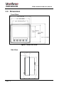
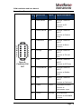
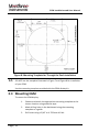
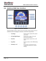
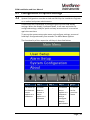
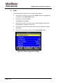
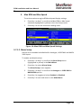
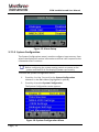
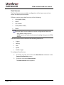
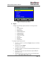
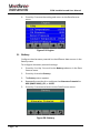
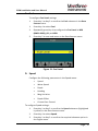
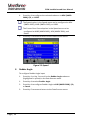
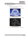
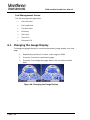
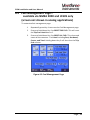
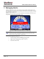
Engine Gateway Monitor
Engine Gateway Monitor (EGM)
Installation and User Manual
Version 1.2
Copyright
Copyright © 2014.
Declarations and Conformance
This equipment is intended for use in international waters as well as coastal sea
areas administered by countries of the E.U. and E.E.A.
In case of any queries, contact our customer service center at
[email protected] or 941-538-7775 ext. 815.
Preface
About this document
This document provides the information required to install, configure, and use the
Engine Gateway Monitor (EGM).
The EGM manual is structured into two chapters, a glossary of terms and definitions,
and an index of key words.
Chapter 1 provides contextual description of the EGM installation and configuration
procedure.
Chapter 2 provides monitor description and steps to use EGM interfaces to monitor
various engine and fuel parameters, and manage alarms.
Document Conventions
Convention
Description
Bold
User Interface terms appear in boldface font.
Note
Note appears with the symbol
above and below the text.
Warning
Warning appears with the symbol
borders above and below the text.
and borders
and
Revision History
Revision Number
Date
1.0
March 2014
1.1
March 2014
1.2
November 2014
EGM Installation and User Manual
Contents
Chapter 1 EGM Installation and Configuration .................... 1
1 Introduction ......................................................................... 3
1.1 Input or Output Compatibility...................................................................4
1.1.1 J1939 ..........................................................................................................4
1.1.2 NMEA 2000.................................................................................................4
1.2 Product Specification...............................................................................5
1.3 Dimensions .............................................................................................6
2 Getting Started .................................................................. 10
2.1 In the Box ..............................................................................................10
2.2 Precautions ...........................................................................................10
3 Installation and Configuration.......................................... 11
3.1 Choosing the Mounting Location...........................................................11
3.2 Mounting Template................................................................................11
3.3 Mounting EGM ......................................................................................12
3.4 Power Connection .................................................................................13
3.5 Data Input Connections.........................................................................13
3.5.1 Connecting to NMEA 2000 (Optional)........................................................13
3.5.2 Connecting to J1939 Engines (CANbus) ...................................................14
3.5.3 Connecting to Non-electronic Engine.........................................................14
3.5.4 Connecting to Rudder Angle Sender .........................................................15
3.5.5 Connecting to Fuel Level Sender...............................................................15
3.5.6 Connecting to a Trim and Tilt Sender ........................................................15
3.5.7 Connecting to GPS NMEA 0183 Signal .....................................................15
3.6 Veethree EGM User Interface ...............................................................16
3.7 Configuration of System Settings ..........................................................17
3.7.1 Main Menu ................................................................................................18
Chapter 2 User Operation.................................................... 41
4 User Interface .................................................................... 43
Page | i
EGM Installation and User Manual
5 Interface View Settings .....................................................44
5.1 Adjusting Interface Brightness .............................................................. 44
5.2 Selecting View Modes .......................................................................... 45
6 EGM Display Gauges.........................................................46
6.1 Changing the Gauge Display................................................................ 48
6.2 Fuel Management Page ....................................................................... 49
7 Managing Alarms...............................................................50
8 About ....... ..........................................................................52
9 Glossary .. ..........................................................................53
10 Index...... ..........................................................................54
Page | ii
EGM Installation and User Manual
Table of Figures
Figure 1: Veethree EGM Console ..............................................................3
Figure 2: EGM Front View ...........................................................................6
Figure 3: EGM Side View ............................................................................7
Figure 4: EGM Rear View............................................................................7
Figure 5: Connector PIN OUT.....................................................................8
Figure 6: Connector PIN OUT.....................................................................9
Figure 7: Mounting Template for Flush Mount Dash Installation .........11
Figure 8: Mounting Template for Through the Dash Installation..........12
Figure 9: EGM User Interface ...................................................................16
Figure 10: User Setup ................................................................................18
Figure 11: Language Setting.....................................................................19
Figure 12: Key Tone Setting......................................................................19
Figure 13: Measuring Units Settings........................................................20
Figure 14: Max RPM and Max Speed Settings ......................................21
Figure 15: Alarm Setup ..............................................................................22
Figure 16: System Configuration Menu ...................................................22
Figure 17: Engine ID Selection .................................................................23
Figure 18: Data Sources Menu .................................................................25
Figure 19: Engine........................................................................................26
Figure 20: Battery .......................................................................................26
Figure 21: Fuel Level..................................................................................27
Figure 22: Speed.........................................................................................28
Figure 23: Rudder Angle............................................................................29
Figure 24: NMEA 2000 Settings ...............................................................30
Figure 25: NMEA 0183...............................................................................30
Figure 26: J1939 Settings..........................................................................32
Figure 27: RPM Calibration .......................................................................33
Figure 28: Analogue Settings....................................................................34
Figure 29: Fuel Management ....................................................................34
Figure 30: Diagnostics Menu ....................................................................35
Figure 31: CAN Viewer ..............................................................................36
Figure 32: CAN Viewer: Log Screen........................................................36
Figure 33: CAN Viewer: Recording Screen ............................................37
Page | iii
EGM Installation and User Manual
Figure 34: CAN Viewer: Statistics Screen .............................................. 37
Figure 35: UART Viewer ........................................................................... 38
Figure 36: IO Debug Screen: Analogue Inputs...................................... 38
Figure 37: IO Debug Screen: Outputs .................................................... 39
Figure 38: Data Viewer.............................................................................. 39
Figure 39: Restore Defaults...................................................................... 40
Figure 40: User Interface .......................................................................... 43
Figure 41: User Interface View Settings ................................................. 44
Figure 42: Day Mode ................................................................................. 45
Figure 43: Night Mode ............................................................................... 45
Figure 44: Changing the Gauge Display................................................. 48
Figure 45: Fuel Management Page ......................................................... 49
Figure 46: EGM Performance Alarm and Warning ............................... 50
Figure 47: Viewing and Suppressing an Alarm ..................................... 51
Figure 48: About EGM............................................................................... 52
Figure 49: Product Details ........................................................................ 52
Page | iv
EGM Installation and User Manual
Chapter 1
EGM Installation and
Configuration
Page | 1
EGM Installation and User Manual
This page is intentionally left blank
Page | 2
EGM Installation and User Manual
1 Introduction
The Veethree Engine Gateway Monitor (EGM) is a 3.5” display with integrated
input and output features.
Figure 1: Veethree EGM Console
The Veethree EGM monitors information available over a NMEA 2000, J1939
or information sent from an analogue engine. EGM is a part of the newgeneration product suite of compact, highly flexible, and rugged CANbus
displays.
Features of Veethree EGM:
•
Compatible with N2K (NMEA 2000), J1939, and non-electronic
engine types with or without an Engine Control Unit (ECU).
•
Acts as an Analogue to NMEA2000 and J1939 to NMEA2000 digital
gateway to allow engine data to be retransmitted to other
NMEA2000 devices.
•
Graphical display of primary engine parameters derived from
traditional analogue engine senders, NMEA 2000, or J1939
networks.
•
Primary display options include parameters related to engine
status, alarms, fuel level, rudder angle, tilt and trim, depth, speed,
and heading.
•
Displays depth, heading, Speed Over Ground (SOG), and speed
over water as available on NMEA2000.
•
Displays SOG & heading as available on NMEA0183
•
ISO and SAE standard icons and test-based multi-language menu.
•
Data is available in multiple formats and measurement units.
•
Output is included for driving an external alarm.
Page | 3
EGM Installation and User Manual
Veethree EGM is driven by CANvu software that provides selectable iconbased display layouts. CANvu software includes a comprehensive multilanguage text-based fault warning and acknowledgement system, and a series
of “hidden until lit” alarms.
To allow multifunctionality and increased input or output capability, Veethree
EGM offers seven analogue inputs, one digital input, and four outputs – one
RS232, two CANbus 2.0B, and a USB 2.0.
The completely sealed Veethree EGM with 320(H) × 240(V) QVGA resolution is
fully sunlight viewable and electrically and environmentally rugged; it provides
tough, flexible, and maintenance-free instrumentation in all types of
environmental conditions. The EGM unit is waterproof and has built-in day and
night modes for comfortable monitoring in all types of visibility and weather
conditions.
Veethree EGM supports three engine types:
•
•
•
NMEA 2000
J1939
Non-electronic
Each EGM display can be allocated to the port (or single), starboard, and/or
the centre engines, and when connected, displays multiple functional data
parameters of an engine. The Veethree EGM interface offers four switchable
gauge display screens and one fuel management screen to enable easy and
real-time monitoring of engine performance.
1.1 Input or Output Compatibility
1.1.1 J1939
J1939 is the engine data protocol that runs over the industrial CANbus that
is used to exchange data between two engines. It is used to synchronize
RPMs on a twin-engine vessel or to drive physical gauges.
1.1.2 NMEA 2000
National Marine Electronics Association (NMEA) 2000 is the standard for
serial data networking of marine electronic devices. It is the plug and play
communication standard that is used to connect marine sensors and
display units within ships and boats. Communication takes place at the
speed of 250 kilobits per second, allowing any sensor to communicate with
any display unit or other devices.
EGM converts, displays, and retransmits NMEA2000 engine data measured
from traditional analogue engine sender signals or from J1939 /
NMEA2000.
Page | 4
EGM Installation and User Manual
EGM as an analogue to NMEA2000 “gateway,” replaces the need for
expensive dedicated converter modules. It provides the user a full-color
interactive engine monitor screen that can be used instead of or along with
the traditional gauges.
1.2 Product Specification
Hardware
Micro Controller Unit
Processor is Free scale iMX 286 at 454 MHz
FLASH Memory
128 MB
Electrical
Display
a-Si TFT LCD 3.5”
Resolution
320(H) × 240(V) QVGA
Active Area
70.08 mm(H) × 52.56 mm(V)
Viewing Angle
130/110 degrees from 6 O’clock
Number of Colors
64 K
Contrast Ratio
300 : 1
Brightness
750 NIT (cd/m2) Full sunlight readable
Power Requirement
10 V to 32 V DC
Sounder
Internal Buzzer
Connection
Two 12 Pin Deutsch DT04-12P Molded in
receptacle
Communication
RS232, (2) CAN BUS 2.0B, USB 2.0
Environmental
0
0
0
0
Operating Temperature
−20 C to +70 C
Storage Temperature
−30 C to +80 C
Degree of Protection
IP 67
Mechanical
Case Material
ABS
Case Color
Anthracite Grey
Dimensions
95 mm(W) × 95 mm(H) × 23 mm rear(D)
Page | 5
EGM Installation and User Manual
1.3 Dimensions
Front View
Figure 2: EGM Front View
Side View
Page | 6
EGM Installation and User Manual
Figure 3: EGM Side View
Rear View
Figure 4: EGM Rear View
Page | 7
EGM Installation and User Manual
Primary Connector
Pin
Wire
Color
Signal
Signal Description
1
Black
GND
GROUND
2
Red
PWR
POWER (10 V DC – 30 V
DC).
Must be protected by
500 MA circuit
breaker/fuse.
3
Brown
RLA1
RELAY/SOLENOID
OUTPUT 1
(External Alarm)
4
Blue/White
RLA2
RELAY/SOLENOID
OUTPUT 2
(Optional gauge light
switch)
Figure 5:
Connector PIN
OUT
5
Black
CAN2(−)
ISOLATED CAN SUPPLY
(−)
6
Red
CAN2(+)
ISOLATED CAN SUPPLY
(+)
7
White
CAN2H
ISOLATED CAN DATA H
8
Blue
CAN2L
ISOLATED CAN DATA L
11
Green
CAN1L
PRIMARY CAN DATA L
12
Yellow
CAN1H
PRIMARY CAN DATA H
Pin 5, Pin 6, Pin 7, and Pin 8 together form a DeviceNet CAN
cable. The DeviceNet CAN cable is used to receive or transmit
the NMEA2000 data.
Pin 11 (Green wire) and Pin 12 (Yellow wire) is a twisted pair,
used for the J1939 input.
Page | 8
EGM Installation and User Manual
Secondary Connector
Pin
Wire Color
Signal
Signal Description
1
Black/White
AN1
SENSOR 1 ANALOG
INPUT
Connect to Oil
Pressure.
2
Brown/White
AN2
SENSOR 2 ANALOG
INPUT
Connect to Coolant
Temp
3
Red/White
AN3
SENSOR 3 ANALOG
INPUT
Connect to Boost
Pressure
4
Orange
AN4
SENSOR 4 ANALOG
INPUT
Connect to Tilt and
Trim.
5
Figure 6:
Connector PIN
OUT
Pink
AN5
SENSOR 5 ANALOG
INPUT
Connect to Oil Temp
6
Yellow/White
AN6
SENSOR 6 ANALOG
INPUT
Connect to Rudder
Angle
7
Blue
AN7
SENSOR 7 ANALOG
INPUT
Connect to Fuel Level.
10
Violet
TACH
TACHOMETER INPUT
Connect to
Tachometer Input.
11
Green
RS32RX
RS232 RECEIVE
Connect to GPS NMEA
Tx Input.
Page | 9
EGM Installation and User Manual
2 Getting Started
2.1 In the Box
The Veethree EGM box contains the following items:
•
Veethree EGM
•
Harness
•
Fitting kit
•
Fixing or mounting template
•
EGM installation and user manual
•
Suncover with Veethree logo
If any of the listed items is found missing or damaged, contact Veethree
Electronics and Marine LLC at [email protected] or 941-5387775 ext. 815.
2.2 Precautions
Follow these safety precautions before installing Veethree EGM:
Page | 10
•
Ensure that all electrical wires are dressed away from moving or
hot engine components.
•
Protect the wires or cables running through the drilled holes using
grommets and by deburring the holes.
•
Disconnect the battery before making any electrical connections.
•
Reconnect the battery only after you have checked and ensured
proper electrical connections.
•
Ensure that the power supply to operate EGM is 10 V to 32 V DC.
EGM Installation and User Manual
3 Installation and Configuration
3.1 Choosing the Mounting Location
•
Choose the installation type – Flush mount dash installation or
through the dash installation (standard).
•
Choose an appropriate location on the dashboard or a suitable
place on the bridge to mount the EGM display unit.
•
The chosen mounting location must allow the operator to easily
control the display and clearly view the display screen.
•
Ensure that there is a direct path to run all the connecting cables or
harness.
3.2 Mounting Template
Veethree EGM mounting templates for “Flush Mount Dash Installation” and
the “Standard through the Dash Installation” are provided along with the
EGM display kit. The mounting template is used to position, mark, and drill
holes on the dashboard to fit the EGM unit.
Figure 7: Mounting Template for Flush Mount Dash Installation
Page | 11
EGM Installation and User Manual
Figure 8: Mounting Template for Through the Dash Installation
DO NOT use the template illustrated in Figure 7 and Figure 8 for installation
of your EGM.
Use the mounting template provided with the EGM display kit.
3.3 Mounting EGM
To mount the EGM display:
Page | 12
1.
Choose and attach the appropriate mounting template to the
chosen location using adhesive tape.
2.
Mark drilling holes in the dashboard using the mounting
template as a guide.
3.
Drill holes using a 3/16” or 4.763 mm drill bit.
EGM Installation and User Manual
Before proceeding to the next step of fixing studding, ensure that
the rubber seal on the rear of EGM display is securely in place
over the USB port access.
4.
Fix the studding (provided in the fitting kit) into the four
positions at the rear of EGM display.
5.
Feed the studding through the four holes drilled on the
dashboard.
6.
Fix and hand tighten the nuts to the studding to secure the
display in its position.
7.
Integrated rubber gasket will seal the display to the dashboard.
3.4 Power Connection
•
Power the EGM display by connecting it to the engine battery. If
the EGM display cuts out due to engine cranking, then connect the
display to domestic battery.
•
Use Black with Red band wire of the harness for the power
connection.
There are two Black wires; any one of these wires can be used for
power connection.
An inline fuse rated at 500 mA or 1A (max) must be provided to
protect the wiring and the display.
3.5 Data Input Connections
3.5.1 Connecting to NMEA 2000 (Optional)
Before connecting the display to the NMEA 2000, check if an
NMEA 2000 backbone is fitted on the vessel.
1.
Connect the NMEA 2000 DeviceNet cable from the display to the
backbone using the T-fitting.
2.
Check if the NMEA backbone is terminated properly. This is done
by finding each end and ensuring that there is an NMEA 2000
termination device at each end of the backbone.
3.
Connect the NMEA 2000 termination device at each end of the
backbone if it is not found to be connected at each end of the
backbone.
Page | 13
EGM Installation and User Manual
4.
If there is a dual station system, connect the system to the NMEA
2000 to share the data between EGMs. (Carry out this step even
if you do not have any other NMEA 2000 equipment).
3.5.2 Connecting to J1939 Engines (CANbus)
1.
Identify the CAN-Low and the CAN-High from the engine ECU
(Refer engine manual for more information).
2.
Connect the Green wire to the CAN-Low.
3.
Connect the Yellow wire to the CAN-High.
Both the Green and Yellow wires must remain twisted together
4.
Check if the J1939 CAN is properly terminated by measuring the
resistance between CAN-High and CAN-Low.
CAN termination resistance must be between 90 ohm and 150
ohm. If the measured resistance is not within the range, add a
120 Ohm resistor between the CAN-High and the CAN-Low.
3.5.3 Connecting to Non-electronic Engine
When connecting the display to a non-electronic engine, signals from the
senders are directly connected to the display harness.
Connect the display to non-electronic engine by making the following
connections:
•
Connect the oil pressure signal from the sender to the Black with
White band wire.
•
Connect the coolant temperature signal from the sender to the
Brown with White band wire.
•
Connect the boost pressure signal from the sender to the Red with
White band wire.
•
Connect the oil temperature signal from the sender to the Pink
wire.
•
Connect the tachometer signal (from W, or R, or AC) to the Violet
wire.
A tachometer signal can be drawn from the W terminal of the
alternator. If W terminal is unavailable, the signal can be drawn
from R or AC terminal of the alternator.
If W, R and AC terminals are unavailable, an alternator shop can
install a tap for the tachometer signal.
Page | 14
EGM Installation and User Manual
3.5.4 Connecting to Rudder Angle Sender
Measure the rudder angle from the rudder angle sender by making the
following connections:
•
Connect the rudder angle signal from the sender to the Yellow with
White band wire of the display harness.
•
Connect the spare Black wire from the display (used for all
analogue senders) to the ground.
3.5.5 Connecting to Fuel Level Sender
Measure the fuel level from the two wire fuel level sender by making the
following connections:
•
Connect the fuel level signal from the sender to the Blue wire of
the display harness.
•
Connect the spare Black wire from the display (used for all
analogue senders) to the ground.
3.5.6 Connecting to a Trim and Tilt Sender
Measure the tilt trim (one per display) from a standard two wire tilt/trim
senders by making the following connections:
•
Connect the trim/tilt sender to the Orange wire of the display
harness.
•
Connect the spare Black wire from the display (used for all
analogue senders) to the ground.
3.5.7 Connecting to GPS NMEA 0183 Signal
The NMEA 0183 GPS is connected to the EGM display to display Speed
Over Ground (SOG) and Course Over Ground (COG). Connect the NMEA
0183 to the Green wire of the display harness.
Page | 15
EGM Installation and User Manual
3.6 Veethree EGM User Interface
Figure 9: EGM User Interface
Veethree EGM provides a robust and user-friendly interface and controls to
enable the users to configure, customize, and monitor engine data.
Page | 16
•
Top Gauge
•
Left and Right Gauges:
Display other engine, fuel, and
functional parameters
•
Data Box
:
Display engine speed, hours, and
depth
•
Page Num
:
Display number of the EGM display
page
•
Soft Keys 1 to 5
:
Scroll, select, and make various
configuration and user’s custom
settings
:
Display engine speed, SOG, Speed
over water
EGM Installation and User Manual
3.7 Configuration of System Settings
System Configuration must be carried out ONLY by the Installation Engineer
or an authorized system administrator.
Commission the EGM display by configuring the various EGM display
settings. When the display is powered down, it will save and store the
configured settings, ready for quick and easy access when it is turned on
again the next time.
To access the system setup main menu and configure settings, press and
hold Key5 for approximately five seconds. The Main Menu appears.
The functionality of the respective soft keys is described below.
Key 1
Key 2
To move up
to choose a
menu
option or a
submenu
To move
down to
choose a
menu
option or a
submenu
Key 3
_
Key 4
Key 5
To select a
menu
option or a
submenu
and to
configure
display
parameters
To return
to the
previous
menu
Page | 17
EGM Installation and User Manual
3.7.1 Main Menu
The configuration options available in the Main Menu are:
•
User Setup
•
Alarm Setup
•
System Configuration
•
About
3.7.1.1 User Setup
Configure the following preferences, display range, and limits in the User
Setup screen.
•
Language
•
Key Tone
•
Units
•
Max RPM
•
Max Speed
Figure 10: User Setup
A. Language
To set the preferred language:
1.
2.
Press Key 1 or Key 2 to scroll to the Language submenu
(highlighted in yellow) in the User Setup menu.
Press Key 4 to select Language.
The Language options list appears.
Page | 18
EGM Installation and User Manual
3. Press Key 1 or Key 2 to scroll to the preferred language.
4.
Press Key 4 to select the preferred language.
5.
Press Key 5 to save and return to the User Setup menu.
Figure 11: Language Setting
B. Key Tone
To set the key tone:
1.
Use Key 1 or Key 2 to scroll to the Key Tone submenu
(highlighted in yellow) in the User Setup menu.
2.
Press Key 4 to select On or Off.
Figure 12: Key Tone Setting
Page | 19
EGM Installation and User Manual
C. Units
To set the measuring units for the engine parameters:
1.
Press Key 1 or Key 2 to scroll to the Units submenu (highlighted
in yellow) in the User Setup menu.
2.
Press Key 4 to select Units.
The Units menu appears.
3.
Press Key 1 or Key 2 to scroll to the various engine parameters
(Temperature, Volume, and so on).
4.
Press Key 4 to select the preferred unit for the selected engine
parameter.
5.
Press Key 5 to save and return to the User Setup menu.
Figure 13: Measuring Units Settings
Page | 20
EGM Installation and User Manual
D.
E. Max RPM and Max Speed
To set the maximum engine RPM and speed display settings:
1.
Press Key 1 or Key 2 to scroll to the Max RPM or Max Speed
submenu (highlighted in yellow) in the User Setup menu.
2.
Press Key 4 to set the maximum reading value.
Figure 14: Max RPM and Max Speed Settings
3.7.1.2 Alarm Setup
Alarms can be enabled and disabled for Analogue, J1939 DM1 and NMEA
2000 inputs.
To enable and disable alarm:
1.
Press Key 1 or Key 2 to scroll to the Alarm Setup menu
(highlighted in yellow) in the Main Menu.
2.
Press Key 4 to select Alarm Setup.
The Alarm Setup screen appears.
3.
Press Key 1 or Key 2 to scroll to the Analogue or J1939 DM1 or
NMEA 2000 options.
4.
Press Key 4 to toggle and select Enabled or Disabled.
5.
Press Key 5 to save and return to the Main Menu.
Page | 21
EGM Installation and User Manual
Figure 15: Alarm Setup
3.7.1.3 System Configuration
The System Configuration menu is used to configure input sources, from
where the display will receive information and how it will respond to the
information that it receives.
Before configuring the system setting, switch on power to the
system and check if all the display(s) power up correctly.
To access the System Configuration menu:
1.
Press Key 1 or Key 2 to scroll to the System Configuration
submenu in the Main Menu (highlighted in yellow).
2.
Press Key 4 to select System Configuration.
The System Configuration menu appears.
Figure 16: System Configuration Menu
Page | 22
EGM Installation and User Manual
The System Configuration menu contains the following submenus:
•
Engine ID
•
Data Sources
•
NMEA 2000 Settings
•
J1939 Settings
•
Analogue Settings
•
Fuel Management
•
Diagnostics
•
Restore Defaults
Engine ID
The Engine ID indicates the engine to which the display is connected.
To configure Engine ID:
1.
Press Key 1 or Key 2 to scroll to the Engine ID submenu in the
System Configuration menu.
2.
Press Key 4 to select Engine ID.
3.
Press Key 4 to set the Engine ID to Port or SGL, Starboard, or
Centre.
Figure 17: Engine ID Selection
Page | 23
EGM Installation and User Manual
Data Sources
The Data Sources menu enables configuration of the input source, from
where the display receives data.
EGM can receive input data from any of the following:
•
N2K (NMEA 2000)
•
J1939
•
I/O senders
•
N183 (NMEA 0183)
•
Demo
All the Data Sources submenu can be configured to Demo and
N2K (NMEA 2000) options.
DEMO option will override the actual reading being sent to EGM
display.
The Data Sources menu contains the following submenus:
•
Engine
•
Battery
•
Fuel
•
Speed
•
Rudder Angle
To configure Data Sources:
1.
2.
Press Key 1 or Key 2 to scroll to the Data Sources submenu in the
System Configuration menu.
Press Key 4 to select Data Sources.
The Data Sources menu appears.
Page | 24
EGM Installation and User Manual
Figure 18: Data Sources Menu
A. Engine
Configure the following engine parameters in the Engine menu:
•
•
•
•
•
•
•
•
•
•
•
•
RPM
Oil temperature
Oil pressure
Boost pressure
Coolant temperature
Coolant pressure
Load percentage
Torque percentage
Tilt-Trim
Engine Hours
Fuel rate
Fuel pressure
To configure engine input sources:
1.
Press Key 1 or Key 2 to scroll to the Engine submenu in the Data
Sources menu.
2.
Press Key 4 to select Engine.
The Engine menu appears.
3.
Press Key 1 or Key 2 to scroll to the required submenu option in
the Engine menu.
4.
Press Key 4 to select the required submenu option (RPM, Oil
temperature, etc.).
5.
Repeatedly press Key 4 to select and set one of the data input
options - N2K (NMEA 2000), J1939, or I/O.
Page | 25
EGM Installation and User Manual
6.
Press Key 5 to save the setting and return to the Data Sources
menu.
Figure 19: Engine
B. Battery
Configure the alternator potential to the different data sources in the
Battery menu.
To configure alternator potential settings:
1.
Press Key 1 or Key 2 to scroll to the Battery submenu in the Data
Sources menu.
2.
Press Key 4 to select Battery.
3.
The Battery menu appears.
4.
Repeatedly press Key 4 to configure the Alternator Potential to
N2K (NMEA 2000), I/O, or J1939.
5.
Press Key 5 to save and return to the Data Sources menu.
Figure 20: Battery
Page | 26
EGM Installation and User Manual
C. Fuel
To configure Fuel Level settings:
1.
Press Key 1 or Key 2 to scroll to the Fuel submenu in the Data
Sources menu.
1.
Press Key 4 to select Fuel.
2.
Repeatedly press Key 4 to configure the Fuel Level to N2K
(NMEA 2000), I/O, or J1939.
3.
Press Key 5 to save and return to the Data Sources menu.
Figure 21: Fuel Level
D. Speed
Configure the following parameters in the Speed menu:
•
Speed
•
Water Speed
•
Depth
•
Heading
•
Mag Variation
•
Depth Offset
•
Course Over Ground
To configure Speed settings:
1.
Press Key 1 or Key 2 to scroll to the Speed submenu (highlighted
in yellow) in the Data Sources menu.
2.
Press Key 4 to select Speed.
3.
Press Key 1 or Key 2 to scroll to the required submenu option in
the Engine menu.
Page | 27
EGM Installation and User Manual
4.
Press Key 4 to configure the selected submenu to N2K (NMEA
2000), I/O, or J1939.
The Speed option in the Speed menu can be configured to N2K
(NMEA 2000), N183 (NMEA 0183), or J1939.
The Course Over Ground option in the Speed menu can be
configured to N183 (NMEA 0183), N2K (NMEA 2000), and
Demo.
5.
Press Key 5 to save and return to the Data Sources menu.
Figure 22: Speed
E. Rudder Angle
To configure Rudder Angle input:
Page | 28
1.
Press Key 1 or Key 2 to scroll to the Rudder Angle submenu
(highlighted in yellow) in the Data Sources menu.
1.
Press Key 4 to select Rudder Angle.
2.
Press Key 4 to configure Rudder Angle to N2K (NMEA 2000), I/O,
or Demo.
3.
Press Key 5 to save and return to the Data Sources menu.
EGM Installation and User Manual
Figure 23: Rudder Angle
NMEA 2000 Settings
Configure the Fluid Level Instance and Gateway in the NMEA 2000 Settings
menu.
A. Fluid Level Instance and Gateway
1.
Press Key 1 or Key 2 to scroll to the NMEA 2000 Settings
submenu (highlighted in yellow) in the System Configuration
menu.
2.
Press Key 4 to select NMEA 2000 Settings.
The NMEA 2000 Settings menu appears.
3.
Press Key 1 or Key 2 to scroll to the Fluid Level Instance option.
4.
Repeatedly press key 4 to configure Fluid Level Instance to 1, 2
or 3.
5.
Press Key 1 or Key 2 to scroll to the Gateway option.
6.
Repeatedly press Key 4 to select Enabled or Disabled.
The Enabled option will transmit all the data, which the display
received over the NMEA2000 network.
The Disabled option will not transmit any data over the
NMEA2000 network.
7.
Press Key 5 to save and return to the System Configuration
menu.
Page | 29
EGM Installation and User Manual
Figure 24: NMEA 2000 Settings
NMEA 0183 Settings
To configure Baud Rate:
1.
Press Key 1 or Key 2 to scroll to the NMEA 0183 Settings
submenu (highlighted in yellow) in the System Configuration
menu.
2.
Press Key 4 to select NMEA 0183 Settings.
The NMEA 0183 menu appears.
3.
Repeatedly press Key 4 to choose and set the appropriate Baud
Rate.
4.
Press Key 5 to save and return to the System Configuration
menu.
Figure 25: NMEA 0183
Page | 30
EGM Installation and User Manual
J1939 Settings
The following settings can be configured in the J1939 Settings menu:
•
Source Address One: Indicates the source of the J1939 engine.
•
Source Address Two: Indicates the source of the transmission.
•
DM SPN Version: Indicates the version number.
•
Display Address: Indicates the address of the EGM display.
•
Speed Source: Determines the type of J1939 PGN used to deliver
the speed value to the display. It can be set to Wheel, or Nav.
To configure J1939 settings:
1.
Press Key 1 or Key 2 to scroll to the J1939 Settings submenu
(highlighted in yellow) in the System Configuration menu.
2.
Press Key 4 to select J1939 Settings.
The J1939 Settings menu appears.
3.
Press Key 1 or Key 2 to scroll to the required submenu in the
J1939 Settings.
4.
Press Key 4 to select the required submenu.
5.
Repeatedly Press Key 4 to select a setting.
6.
Press Key 5 to save and return to the System Configuration
menu.
Configure Source Address Two as GLB to indicate that the
display accepts data from any source.
Configure the Source Address Two option only when an
alternator is used.
Consult your engine supplier for the appropriate SPN version, if
you have problem reading alarm data.
In single engine setup, the default display address is always 40. It
is SAE recommendation.
Page | 31
EGM Installation and User Manual
Figure 26: J1939 Settings
Analogue Settings
The following analogue parameters can be configured and set using the
Analogue Settings menu:
RPM Calibration
Oil Pressure
Coolant Temp
Boost Pressure
Tilt-Trim
Oil Temp
Rudder Angel
Fuel Level
•
•
•
•
•
•
•
•
A. RPM Calibration
RPM calibration is a simple multiplier. While the engine is running on
idle, adjust the number in brackets to the idle RPM specified in the
engine manual.
To configure RPM calibration:
1.
Press Key 1 or Key 2 to scroll to Analogue Settings (highlighted in
yellow) in the System Configuration menu.
The Analogue Settings menu appears.
Page | 32
2.
Press Key 1 or Key 2 to scroll to the RPM Calibration option in
the Analogue Settings menu.
3.
Press Key 4 to select RPM Calibration.
4.
Repeatedly press Key 4 to set the idle RPM rate.
EGM Installation and User Manual
Figure 27: RPM Calibration
B. To Configure other Analogue Settings:
1.
Press Key 1 or Key 2 to scroll to the required submenu
(highlighted in yellow) in the Analogue Settings menu.
2.
Press Key 4 to select a parameter.
The analogue parameter screen appears.
3.
Repeatedly Press key 1 to select the Calibration data box or the
Adjust data box.
4.
Choose “WITH GAUGE” option if application will use a gauge and
the EGM display.
Due to hardware limitations, on a 24V system the Analog Inputs
will not function properly when used parallel with other gauges.
5.
Press Key 2 or Key 3 to adjust the value in Calibration or Adjust
data box.
6.
Press Key 5 to save and return to the Analogue Settings menu.
Page | 33
EGM Installation and User Manual
Figure 28: Analogue Settings
Fuel Management – available via NMEA 2000 and J1939
only (screen not shown in analog applications)
The maximum capacity of the fuel tank (size) can be configured in the Fuel
Management screen.
To configure the fuel tank size:
1.
Press Key 1 or Key 2 to scroll to the Fuel Management submenu
(highlighted in yellow) in the System Configuration menu.
2.
Press Key 4 to select Fuel Management.
3.
Repeatedly press Key 4 to set Tank Size (in liters).
4.
Press Key 5 to save and return to the System Configuration
menu.
The Fuel Management menu appears.
Figure 29: Fuel Management
Page | 34
EGM Installation and User Manual
Each display can be connected to only one fuel tank. Hence, the
display can only read one fuel tank sender.
Diagnostics Menu
The Diagnostics Menu displays the complete information that the EGM
display is receiving from different networks.
The Diagnostics Menu contains the following submenus:
•
•
•
•
•
CAN Viewer
UART Viewer
IO Debug Screen
Data Viewer
Frame Counter
To access Diagnostics Menu:
1.
Press Key 1 or Key 2 to scroll to the Diagnostics Menu
(highlighted in yellow) in the System Configuration menu.
2.
Press Key 4 to select the Diagnostics Menu.
The Diagnostics menu appears.
Figure 30: Diagnostics Menu
A. CAN Viewer
The CAN Viewer displays the raw CAN data that is received and sent.
Both CAN PORT 1 data and CAN PORT 2 data can be viewed in this
viewer.
To view raw CAN data:
1.
Press Key 1 or Key 2 to scroll to the CAN Viewer submenu
(highlighted in yellow) in the Diagnostics menu.
2.
Press Key 4 to select CAN Viewer.
Page | 35
EGM Installation and User Manual
The CAN Viewer screen appears.
Figure 31: CAN Viewer
3.
Press Key 1 to pause data recording.
4.
Press Key 2 to change the port (1 or 2), if required.
5.
Press Key 3 to select LOG.
The log screen appears.
Figure 32: CAN Viewer: Log Screen
6.
Page | 36
Press Key 3 to clear the log.
7.
Press Key 2 to change the port (1 or 2), if required.
8.
Press Key 1 to start recording the CAN data.
EGM Installation and User Manual
Figure 33: CAN Viewer: Recording Screen
9.
Press Key 1 to stop recording.
10. Press Key 5 to save and return to the previous options
11. Press Key 4 to select STATS.
The statistics screen appears.
Figure 34: CAN Viewer: Statistics Screen
B. UART Viewer
UART Viewer displays the raw NMEA 0183 data that is being received.
To view NMEA 0183 data in the UART Viewer:
1.
Press Key 1 or Key 2 to scroll to the UART Viewer submenu
(highlighted in yellow) in the Diagnostics menu.
2.
Press Key 4 to select UART Viewer.
The UART Viewer screen appears.
Page | 37
EGM Installation and User Manual
3.
Press Key 5 to save and return to the Diagnostics Menu.
Figure 35: UART Viewer
C. IO Debug Screen
The IO Debug screen displays analog inputs, outputs and digital
outputs. You can also check the display for any bugs.
To view analog inputs, outputs and digital outputs:
1.
2.
Press Key 1 or Key 2 to scroll to the IO Debug Screen submenu
(highlighted in yellow) in the Diagnostics menu.
Press Key 4 to select IO Debug Screen.
The IO Debug Screen appears.
3.
Press Key 1 to view Analogue Inputs.
4.
Press Key 2 or Key 3 to view the outputs.
5.
Press Key 5 to save and return to the Diagnostics Menu.
Figure 36: IO Debug Screen: Analogue Inputs
Page | 38
EGM Installation and User Manual
Figure 37: IO Debug Screen: Outputs
D. Data Viewer
The Data Viewer screen displays the data such as Units, source, and
Add that the display is reading from networks.
To view data in the Data Viewer:
1.
2.
Press Key 1 or Key 2 to scroll to the Data Viewer submenu
(highlighted in yellow) in the Diagnostics menu.
Press Key 4 to select Data Viewer.
The Data Viewer Screen appears.
3.
Press Key 1 and Key 2 to scroll up and down the data rows in the
Data Viewer screen.
4.
Press Key 5 to save and return to the Diagnostics Menu.
Figure 38: Data Viewer
Page | 39
EGM Installation and User Manual
Restore Defaults
The custom or system specific configuration can be restored to company
default settings and to enable re-configuration. Note that all settings
except engine hour setting will be restored to their default settings.
To restore company default settings:
1.
Press Key 1 or Key 2 to scroll to the Restore Defaults submenu
(highlighted in yellow) in the System Configuration menu.
2.
Press Key 4 to select Restore Defaults.
The Restore Defaults screen appears.
Figure 39: Restore Defaults
Page | 40
EGM Installation and User Manual
Chapter 2
User Operation
Page | 41
EGM Installation and User Manual
This page is intentionally left blank
Page | 42
EGM Installation and User Manual
4 User Interface
Figure 40: User Interface
Key 1
To select and view a display page
Key 2
To select a gauge
(The selection of gauge is indicated by a red rectangular
box.)
Key 3
To choose a parameter that will be displayed in the
selected gauge on the page
Key 4
To display alarm screen
(This is applicable only when an alarm is active)
Key 5
To open the display settings menu – brightness and
view modes
To access the Main Menu (hold down Key 5 for
approximately five seconds)
Page | 43
EGM Installation and User Manual
5 Interface View Settings
Veethree EGM provides the option to adjust user interface brightness and view
modes to suit day and night operational requirements.
A simple user-friendly toolbar facilitates the functionality.
5.1 Adjusting Interface Brightness
To adjust user interface brightness of EGM:
1.
Press Key 5 to open the interface view settings menu.
The view settings tool bar appears.
2.
Press Key 1 to decrease and key 2 to increase the brightness of
the EGM display screen.
Figure 41: User Interface View Settings
Page | 44
EGM Installation and User Manual
5.2 Selecting View Modes
To select view modes:
1.
Press Key 5 to open the interface view settings menu.
The view settings tool bar appears.
2.
Press Key 3 to set the EGM display screen to the day mode.
Figure 42: Day Mode
3.
Press Key 4 to set the EGM display screen to the night mode.
Figure 43: Night Mode
4.
Press Key 5 to save and return to the EGM main interface.
Page | 45
EGM Installation and User Manual
6 EGM Display Gauges
Veethree EGM has 4 gauge display pages and 1 fuel management page. The
top gauge includes the data box.
Top Gauge
The Top Gauge in the page is to display:
Icon
Parameter
Engine Speed
Speed over water
Speed over ground
The data box displays:
•
Engine speed
•
Engine hours
•
Depth
Bottom Left and Right Gauge
The bottom left and bottom right gauge in the page are to display:
Parameter
Oil Temperature
Oil Pressure
Boost Pressure
Page | 46
Icon
EGM Installation and User Manual
Parameter
Icon
Coolant Temperature
Coolant Pressure
Torque Percentage
Tilt & Trim
Alternator Potential
Fuel Pressure
Fuel Level
Throttle Percentage
Rudder Angle
Fuel Rate
Depth
Heading
Course Over Ground (COG)
Economy
Load Percentage
Page | 47
EGM Installation and User Manual
Fuel Management Screen
The fuel management page data:
•
Fuel rate total
•
Fuel used total
•
Trip fuel used
•
Economy
•
Fuel level
•
Time till 0
•
Distance till 0
6.1 Changing the Gauge Display
To change the gauge display or customize parameter gauge display on a view
page:
1.
Repeatedly press Key 1 to select a view page on EGM.
2.
Press Key 2 to select a parameter gauge.
3.
Press Key 3 to change the gauge data to the currently available
data.
Figure 44: Changing the Gauge Display
Page | 48
EGM Installation and User Manual
6.2 Fuel Management Page –
available via NMEA 2000 and J1939 only
(screen not shown in analog applications)
To customize fuel management page:
1.
Repeatedly press Key 1 to access the Fuel Management page.
2.
Press and hold down Key 2 to RESET TRIP FUEL. This will reset
the Trip Fuel Used data to 0.
3.
Press and hold down Key 3 to RESET ALL FUEL. This clears and
resets all the counters - Fuel Used including Port, Starboard,
Centre, and Total. Holding down Key 3 will also clear the Trip
Fuel counter.
Figure 45: Fuel Management Page
Page | 49
EGM Installation and User Manual
7 Managing Alarms
Veethree EGM has a built-in alarm feature that provides visible alarms and
warnings when any performance parameter falls below a threshold or exceeds
the permissible upper limit.
When an alarm is active, an icon that represents a parameter will flash in red
along with a popup warning message in red.
Figure 46: EGM Performance Alarm and Warning
The Alarms menu is active only if there are any active alarms that
have not been viewed and/or suppressed.
The currently supported alarms are:
Page | 50
•
Low Oil Pressure Alarm of 200 kPa (2 bar, 29 Psi)
•
High Coolant Temperature of 100 C (212 F)
•
Low Fuel Level of 10%
0
0
EGM Installation and User Manual
To manage alarms:
1.
Press key 4 to view the Alarms screen.
The alarm suppression screen appears.
Figure 47: Viewing and Suppressing an Alarm
2.
Press Key 1 or Key 2 to scroll and view the active alarms.
3.
Press Key 4 to suppress an active alarm.
4.
Press Key 5 to return to the main EGM interface.
Page | 51
EGM Installation and User Manual
8 About
The About page gives software version information and units (Software) serial
number.
Figure 48: About EGM
Figure 49: Product Details
Page | 52
EGM Installation and User Manual
9 Glossary
Term/Phrase
Definition/Description
CANbus
Controller Area Network bus is a standard that allows
microcontrollers and devices to communicate with each
other within a vehicle, without any host computer.
COG
Course Over Ground is the actual path of a vessel with
respect to the seabed, measured in degrees.
ECU
Engine Control Unit is a type of electronic control unit
that controls a series of actuators on an internal
combustion engine to ensure optimal engine
performance.
EGM
Engine Gateway Monitor is a 3.5” display with
integrated input and output features.
J1939
J1939 is an engine data protocol that runs over the
industrial CANbus and is used to exchange data
between two engines.
Micro Controller
Unit
Micro Controller Unit is a chip that contains the
processor, ROM, RAM, and an I/O control unit.
NMEA
National Marine Electronics Association (NMEA) 2000 is
the standard for serial data networking of marine
electronic devices.
Non-electronic
engine
Non-electronic engine is an engine that is not
controlled by an ECU / ECM.
It is also termed as “Mechanical Engine” or "Non-ECU
Engine”.
SOG
Speed Over Ground is the speed of the vessel relative
to the surface of the earth.
Page | 53
EGM Installation and User Manual
10 Index
A
About ..............................................52
Adjusting Interface Brightness........44
Alarm Setup ....................................21
Analogue Settings ...........................32
B
Fuel Management ..........................34
Fuel Management Page..................49
I
In the Box .......................................10
IO Debug Screen .............................38
J
Battery ............................................26
C
CAN Viewer.....................................35
CANvu software................................4
Changing the Gauge Display ...........48
Choosing the Mounting Location....11
Configuration of System Settings ...17
J1939 ................................................4
J1939 Settings.................................31
K
Key Tone.........................................19
L
D
Language ........................................18
Data Input Connections ..................13
Data Sources...................................24
Data Viewer ....................................39
Diagnostics Menu ...........................34
Dimensions .......................................6
M
E
EGM Display Gauges.......................46
Engine .............................................25
Engine Gateway Monitor..................3
Engine ID.........................................23
F
Fluid Level Instance and Gateway ..29
Fuel .................................................27
Page | 54
Managing Alarms............................50
Max RPM and Max Speed...............21
Mounting EGM ...............................12
Mounting Template........................11
N
NMEA 0183 Settings.......................30
NMEA 2000 ......................................4
NMEA 2000 Settings.......................29
EGM Installation and User Manual
S
P
Power Connection ......................... 13
Precautions .................................... 10
Primary Connector........................... 8
Product Specification ....................... 5
R
Restore Defaults ............................ 40
RPM Calibration ............................. 32
Rudder Angle ................................. 28
Secondary Connector .......................9
Selecting View Modes.....................45
Speed..............................................27
System Configuration .....................22
U
UART Viewer...................................37
Units ...............................................20
User Setup ......................................18
V
Veethree EGM User Interface.........16
Page | 55
EGM Installation and User Manual
Page | 56
EGM Installation and User Manual
Page | 57
Veethree Electronics and Marine LLC
2050 47th Terrace East
Bradenton, Florida 34203 USA
Tel Office: 941-538-7775
Fax: 941-755-1222
www.V3instruments.com