1
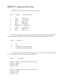
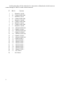
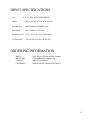
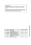
DIP053 QUAD PC/AT TO
CAN ADAPTER MODULE
14005301
D.I.P. Inc
P.O. Box 9550
Moreno Valley, CA
92552-9550
909-924-1730
TABLE OF CONTENTS
INTRODUCTION ------------------------------------------------ 1
HARDWARE DESCRIPTION --------------------------------Optical Isolation -------------------------------Missing Cable Detect -------------------------CAN Bus Interface ----------------------------DIP053 Connector Pin Out -------------------Network Jumpers ------------------------------Transceiver Power -----------------------------Terminating Resistors --------------------------
1
2
2
2
3
5
5
7
INSTALLING THE DIP053 -----------------------------------Base Address -----------------------------------Interrupts ----------------------------------------Auxiliary Switches -----------------------------
7
7
9
10
DIP053 SPECIFICATIONS ------------------------------------ 11
Please Note:
MKS Instruments provides these documents as the latest version for the revision indicated.
The material is subject to change without notice, and should be verified if used in a critical
application.
INTRODUCTION
The DIP053 provides a general purpose quad CAN bus interface for IBM PC/AT based
personal computers. The unit relies on the Intel 82C527 CAN interface component to provide access
to the CAN network. The hardware interface includes optical isolation for the CAN signals, reverse
polarity protection for the CAN bus power and signal lines and a circuit to detect when the CAN bus
power is removed.
Application software interfaces to the DIP053 through an interrupt driven device driver.
Commands are available to configure both the PC specific interface as well as the CAN network
parameters.
The DIP053 will support both SDS and DeviceNet systems. The unit is supported by two
software monitor packages which provide a simple, engineering level interfaces to the networks.
The SDS053 software operates with the DIP053 PC to CAN adapters to provide a convenient
system development tool for SDS based CAN networks. The monitor operates under MS-DOS
(version 3.1 and above).
The DNET053 software operates with the DIP053 PC to CAN adapters to provide a convenient system development tool for DeviceNet based CAN networks.
HARDWARE DESCRIPTION
The 82C527 CAN controller provides 256 internal registers shared between 15 CAN message buffers and a set of general purpose configuration registers and I/O ports.
The device appears to the PC/AT bus as two interface registers, a data POINTER and a data
VALUE. The data pointer may be set to auto-increment to speed up multi-byte transfers.
Internal interrupt hardware will automatically prioritize interrupt requests to the single
hardware interrupt pin. Extensive interrupt masking may be done.
The 82C527 CAN signals are routed to HCPL7101 opto-couplers which provide 1 megabit
data transfer capability. The opto-couplers in turn are routed to Signetics 82C250 CAN transceivers
which provide an ISO/DIS 11898 compatible CAN bus interface.
The ‘isolated’ side of the opto-couplers include a separate power regulator which derives
power from either the CAN bus or the PC power. Power detection circuitry provides a signal back to
the 82C527 to indicate that bus power is available.
1
Optical Isolation
The HCPL7101 optical isolators will support data rates up to 1 megabit/second. The circuits
are biased such that if the CAN controller (82C527) disables the output drive signals then the corresponding CAN signals enter a submissive level. This circuitry is required to support ‘listen only’ and
‘autobaud’ capability.
Each channel has a separate bus power regulator. Power may be routed from the external
CAN bus power or from the internal PC +12 volt power.
Missing Cable Detect
Hardware support to detect a missing cable (no bus power) is provided for each channel. The
information is available through the 82C527 general purpose parallel port interface, port P1, bit 0.
If internal power is used the missing cable detection function is disabled and the CAN channel is not optically isolated.
CAN Bus Interface
Each CAN channel may be routed to a separate DB-9 connector. Two connectors are
mounted directly on the adapter. The third and fourth channels are pinned out to ribbon headers,
designed to map to two additional DB-9 connectors mounted on standard PC metal peripheral
adapter shells.
In some applications it may be desired to provide an alternate pin-out for the two on-board
DB-9 connectors to allow all four CAN channels to be routed to the on-board connectors.
The pin-out for the DB-9 connectors is shown below. The alternate function indicates the
pin-out which allows four can channels to be mapped to the two on-board DB-9 connectors.
When the alternate function pin-out is used CAN channels 0 and 2 will be grouped on one
connector and channels 1 and 3 on the second connector. The channels have individual pins for bus
power, ground and signal leads. The shield (connected internally to chassis ground) share a common
connection.
2
DIP053 Connector Pin Out
The DIP053 pin-out for the DB9 connectors are as follows:
DB-9
1
2
3
4
5
6
7
8
9
Function
none
CAN L
BUS none
none
Shield Ground
CAN H
none
BUS +
Alternate Function
CAN L (2/3)
CAN L (0/1)
BUS - (0/1)
BUS - (2/3)
CAN H (2/3)
Shield Ground
CAN H (0/1)
BUS + (2/3)
BUS + (0/1)
In the normal configuration each of the four CAN channels are connected to a separate DB-9
connector. External 10 pin header to DB-9 cable assemblies are required for channels 3 and 4.
Channel
0
1
2
3
Connector
P1
P3
P5 (requires 10 pin to DB-9 cable)
P9 (requires 10 pin to DB-9 cable)
To enable channels 2 (or 3) to be routed to connectors P1 or P3 as shown in the Pin-out table
above it is necessary to install four jumpers as shown below.
Jumpers
Description
E9-E10
E11-E12
E12-E14
E15-E16
CAN2H Connects Channel 2 to P1 per above
CAN2L
BUS +
BUS -
E17-E18
E19-E20
E21-E22
E23-E24
CAN3H Connects Channel 3 to P3 per above
CAN3L
BUS +
BUS 3
A third option allows all four channels to be connected to a ribbon header which in turn can
connect through to a DB-26 or other external connector.
4
P7
DB-26
1
2
3
4
5
6
7
8
9
10
11
12
13
14
15
16
17
18
19
20
21
22
23
24
25
26
1
14
2
15
3
16
4
17
5
18
6
19
7
20
8
21
9
22
10
23
11
24
12
25
13
-
Function
Channel 0 CAN-H
Channel 0 BUS Gnd
Channel 0 CAN-L
Channel 0 BUS Gnd
Channel 1 CAN-H
Channel 1 BUS Gnd
Channel 1 CAN-L
Channel 1 BUS Gnd
Channel 2 CAN-H
Channel 2 BUS Gnd
Channel 2 CAN-L
Channel 2 BUS Gnd
Channel 3 CAN-H
Channel 3 BUS Gnd
Channel 3 CAN-L
Channel 3 BUS Gnd
Channel 0 BUS +
Channel 0 BUS +
Channel 1 BUS +
Channel 1 BUS +
Channel 2 BUS +
Channel 2 BUS +
Channel 3 BUS +
Channel 3 BUS +
No Connect
No Connect
Network Jumpers
The DIP053 is provided with an optically coupled CAN transceiver. To provide full isolation
between the CAN network and the PC the transceiver circuit requires a separate power source. This
is typically provided by a network wide power supply carried on the BUS + and BUS GND signals.
Transceiver Power
Each channel has a 10 position jumper block to allow selecting the power source.
Jumper Block
P2
P4
P6
P8
Description
Channel 0 power selector
Channel 1 power selector
Channel 2 power selector
Channel 3 power selector
P2..P8 JUMPER BLOCK
To Pwr +
o---o
BUS +
PC +12 source o o
N.C.
o o
PC +12 source
N.C
To Pwr -
o---o
BUS -
PC Gnd
o o
PC Gnd
5
These jumper options should be used when the BUS + and BUS GND signals are to be used
to power the transceiver.
P2..P8 JUMPER BLOCK
To Pwr + o o BUS +
|
PC +12 source o o PC +12 source
N.C.
To Pwr |
PC Gnd
o o
N.C
o o
BUS -
o o
PC Gnd
These jumper options should be used when the PC +12 power is to be used to power the
transceiver. Note that this configuration does not provide galvanic isolation between the CAN
network and the PC.
To Pwr +
o---o
BUS +
PC +12 source o---o
N.C.
o o
PC +12 source
N.C
To Pwr -
o---o
BUS -
PC Gnd
o---o
PC Gnd
A third option allows the PC power to power both the local transceivers as well as the CAN
network. Current limiting devices on the DIP053 restrict the available bus power to 100 mA. for
each CAN channel.
6
Terminating Resistors
Jumper options are included to provide a 120 ohm, 1/2 watt termination resistor resident on
the DIP053 for each channel. install the jumper to enable the terminating resistor.
Jumper
Channel
E1-E2
E3-E4
E5-E6
E7-E8
Channel 0
Channel 1
Channel 2
Channel 3
INSTALLING THE DIP053
The DIP053 PC to CAN adapter may be installed in an ISA compatible Personal Computer.
The module occupies 16 consecutive locations within the processor I/O space. Prior to installation
the user must set both the base address and the interrupt level to be used by the adapter.
Base Address
The 82C527 requires two byte addresses for the processor interface and a single interrupt
line. The four controllers occupy 16 consecutive addresses in the PC address space, with each
82C527 positioned at an even bus address. The I/O base address is selectable from 1 of 8 unique
addresses, allowing a system to potentially contain up to 8 DIP053’s.
For each channel the pointer register is located at an even address. The data register is located
at odd addresses. To read/write a specific 82C527 register the register number must be loaded to the
pointer register and then the data read/written using the data register.
Switch
Address
S3 S2 S1
OFF
OFF
OFF
OFF
ON
ON
ON
ON
OFF
OFF
ON
ON
OFF
OFF
ON
ON
OFF
ON
OFF
ON
OFF
ON
OFF
ON
200 H
240 H
280 H
2C0 H
300 H
340 H
380 H
3C0 H
7
Auto-increment allows for faster transfers by automatically incrementing the register pointer
after each read or write to the data register.
Base +
8
Description
0
1
2
3
4
5
6
7
Channel 0 pointer register
Channel 0 data register
Channel 1 pointer register
Channel 1 data register
Channel 2 pointer register
Channel 2 data register
Channel 3 pointer register
Channel 3 data register
8
9
A
B
C
D
E
F
Reserved
Channel 0 data register, auto-increment
Reserved
Channel 1 data register, auto-increment
Reserved
Channel 2 data register, auto-increment
Reserved
Channel 3 data register, auto-increment
Interrupts
The 82C527 interrupt lines are OR’d to drive a single interrupt line on the PC backplane. To
assist in interrupt handling the processor may read parallel port 2 of channel 0 to determine which of
the four units generated the interrupt request. Multiple devices may have outstanding interrupts.
Interrupts are a very scarce resource on heavily populated personal computers. The following
table shows the ‘standard’ use of interrupts for AT and 386/486 machines.
The interrupt level is determined using the DIP switch positions 4-6. The hexadecimal values
in parenthesis are the corresponding interrupt level to be coded in the SDSMON and DNETMON
initialization files.
Switch
S6 S5 S4
OFF
OFF
OFF
OFF
ON
ON
ON
ON
OFF
OFF
ON
ON
OFF
OFF
ON
ON
Interrupt
OFF
ON
OFF
ON
OFF
ON
OFF
ON
3 (3)
4 (4)
5 (5)
7 (7)
10 (A)
11 (B)
12 (C)
15 (F)
Normal Usage
COM2/4
COM1/3
LPT2,Network,CD
LPT1
General I/O
General I/O
General I/O
General I/O
9
Auxiliary Switches
The DIP053 provides two unused switch positions which may be used to provide auxiliary
information to the application software. Standard DIP device drivers use this information to determine the number of channels available on the adapter. The information is available on parallel port 2
of channel 0.
When used with DIP device drivers the following interpretation is given to switch positions
S7 and S8.
Switch
S8 S7
OFF
OFF
ON
ON
10
OFF
ON
OFF
ON
Populated
1
2
3
4
Normal Usage
One 82C527
Two 82C527
Three 82C527
Four 82C527
DIP053 SPECIFICATIONS
Size
8" X 4.5" (ISA BUS COMPATIBLE)
Power
5 volt @ 100 mA, 12 volt @ 80 mA bus
Bus Interface
optical isolation, ISO/DIS 11898
Bus Speed
up to 1 Mbit/sec, 120 nodes
Interrupt Levels
3,4,5,7,10,11,12,15 (user selectable)
I/O Addresses
200,240,280,2C0,300,340,380,3C0
ORDERING INFORMATION
DIP053
DIP053-DRV
13005301
CANMON53
- Quad PC to CAN Bus Interface Adapter
- C based interface example code
- DIP053 User Manual
- MONITOR SOFTWARE FOR DIP053
11