1
energy for a better world
USER MANUAL
TRI-DESIGN
Version 1.0 | November 2009
4
4
Features
Special Feature
5
5
Setup
Uninstalling
6
6
7
8
8
9
User Guide
Project Management
Location
Project Data
Parameter Enquiry
Stand-system
11
12
13
13
14
14
15
Adding Restricted Areas
Add Modules
Other Options of the Graphic Design
Current Bill of Materials
Print-out
Export in CSV Format
Other Features
16
17
18
19
Software Update
Updating the Module Data Base
Contact
Terms of Use
Data Bases & Update
10
PV Module Selection
Graphic Design
6
Programme Structure
Programme
5
System Requirements
Installation
4
The Software
Overview
TABLE OF CONTENTS
Export of the BOM
BOM with all components
Graphic project design
4_Overview
Selection of save location
A special feature of the TRI-DESIGN software is its export functionality. This
functionality enables the user to export and directly send the BOM for installation parts and solar modules to TRITEC. This functionality significantly
simplifies the design of solar systems and thus allows even more efficient
work.
Special Feature
The TRI-DESIGN software has the following features:
UÊ-«iÊ«ÀiVÌÊ>>}iiÌ
UÊÊ-ÌiÊ`iÌiÀ>ÌÊÊiÀ>Þ]Ê-ÜÌâiÀ>`]ÊÀ>Vi]Ê-«>]Ê
Italy and Austria
UÊ-vÌÜ>ÀiÊ>Û>>LiÊÊiÀ>]Ê}Ã
]ÊÀiV
]Ê-«>Ã
Ê>`ÊÌ>>Ê
UÊÊiÃ}Ê>`ÊV>VÕ>ÌÊvÊÌ
iÊ/,/
Ê«
ÌÛÌ>VÊÕÌ}ÊÃÞÃÌiÊ
TRI-STAND for pitched and flat roofs with different installation types
UÊÕÌ>ÌVÊV>VÕ>ÌÊvÊÕÌ}ÊÃÕ}}iÃÌÃÊvÀÊÌ
iÊÀvÊÃÕÀv>ViÊ
UÊÊ
Ài>ÌÊvÊ>Ê"ÊÊvÊ>ÌiÀ>îÊvÊ>Ê`ÕiÃÊ>`ÊÃÌ>>ÌÊ
components for a PV system
UÊ
i>ÀÞÊ>ÀÀ>}i`Ê`ë>ÞÊvÊ>ÊÀiÃÕÌÃÊ
Uninstalling TRI-DESIGN
Copying of data
In order for the software to run optimally, the following system requirements
must be met:
UÊ°ÊnääÊâÊ*
UÊ°Êx£ÓÊÊ,
UÊ°Ê£ääÊÊvÀiiÊ
>À`Ê`ÃVÊë>ViÊ
UÊ£äÓ{ÊÝÊÇÈnÊÌÀÊÀiÃÕÌ
UÊVÀÃvÌÊ7`ÜÃÊ8*ÊÀÊ
}
iÀ
UÊVÀÃvÌ° /ÊÀ>iÜÀÊÓ°äÊÀÊ
}
iÀ
The TRI-DESIGN software is a software specifically developed by TRITEC for
the design and calculation of photovoltaic systems. The programme and its
integrated calculation and design information provide support for project
engineering and preparation of offers. The TRI-DESIGN software allows any
photovoltaic system and its technical aspects to be planned easily, quickly and
efficiently.
In order to remove the programme completely from the computer, you will
have to uninstall it in the Control Panel. Click on the Start button of the taskbar, then the button Programs and FunctionsÊ7`ÜÃÊ6ÃÌ>®°Ê
V}ÊÊÌ
iÊ
TRI-DESIGN programme and then on UninstallÊ«iÃÊÌ
iÊÜâ>À`ÊÌÊÕÃÌ>Ê
the programme. Finally, clicking on Uninstall in the appearing window
removes the programme and all related files from the computer.
Uninstalling
This step completes the installation of the TRI-DESIGN software. The last
window allows you to choose whether the software should be started immediately or at a later time manually.
Start the installation by double clicking on the file Setup.exe°Ê7iÊÀiVi`Ê
to close all other applications during the installation, so system files can be
replaced without restart. After selecting the save location for the programme
and programme files, a Start menu folder can be selected where the link to
start the programme is created.
Clicking on Continue starts the installation of the programme on the computer.
You can quit the software setup at any time by clicking on Cancel. Installation
of the programme and copying of the files may take some time.
Setup
System Requirements
The Software
Features
INSTALLATION
OVERVIEW
Installation_5
Opening and editing a saved project
Archived TRI-DESIGN projects
Simple navigation in the programme
The 7 main areas
Programme overview
6_Programme
Opening a project
You create a new project by clicking on File > New project. Every time you start
Ì
iÊÃvÌÜ>Ài]ÊÌ
iÊ«À}À>iÊ«iÃÊ>Êi«ÌÞÊ«ÀiVÌÊ>ÕÌ>ÌV>Þ°Ê7iÊÀiVommend saving this at this point in time to the desired save slot by clicking
File > Save project as. Doing this, all you have to do during the design process
is clicking on Save project to save the data to the desired location.
To open an existing project, click on File > Open project°Ê>Û}ÊÃiiVÌi`ÊÌ
iÊ
desired project, you can open and edit it with TRI-DESIGN.
The TRI-DESIGN software can be used to design several systems. The data of
each project can be saved and recovered at any later time. In general, we
recommend saving the project regularly during its creation.
Project Management
After setting the main parameters of the programme, the seven main areas
must be filled out one after the other. Keeping to this sequence ensures the
best possible and efficient way of working with the TRI-DESIGN software.
On top of the screen you will find another navigation aid. The buttons Back
and Forward allow you to go back or forward by one step.
User Guide
iiÀ>ÊÃiÌÌ}ÃÊ>`ÊvÕVÌÃÊvÀÊiÝ>«i]Ê>}Õ>}i]ÊÛiÜ]Ê«ÀÌ}Ê>`Ê
iÝ«ÀÌ}Ê`>Ì>®Ê>ÀiÊ>VViÃÃLiÊÛ>ÊÌ
iÊiÕÊL>À°Ê/
iÃiÊvÕVÌÃÊ>ÀiÊiÝ«>i`Ê
in the section Other Features of this manual.
The programme can be subdivided into seven main areas. In Location enter
site data related to the respective project, under Project Data information
such as project number, address and contact data are allocated. The features
of the roof, on which the system is to be installed, are entered in the area
Parameter Enquiry, before you select the mounting system under Stand-system.
Graphic design designs the system for the roof based on the entered data,
before Current BOM displays a bill of materials of all components of the
mounting system and the modules. The area Printout Export allows you to
print all relevant data and export the BOM.
Programme Structure
PROGRAMME
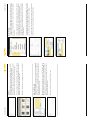
Selecting the terrain category
Selecting the snow and wind load zone
using the map
Entering location information
Selecting the country from the list
Site data
Saving a project
Terrain category: The terrain category can be set by either selecting one of
the icons or by entering it manually. To see an explanation of the respective
category simply drag the cursor on its icon. The explanation appears in a
separate field.
Snow / wind load value: If the wind and snow load values are known or the
site is outside the provided countries, you can alternatively enter these values
directly into the fields Snow load value and Wind load value. This replaces
ÃiiVÌ}ÊÌ
iÊÜ`Ê>`ÊÃÜÊ>`ÊâiÊ>`ÊÌ
iÊÌiÀÀ>ÊV>Ìi}ÀÞ°
Snow / Wind load zone:ÊÌiÀÊÌ
iÊÃÜÊ>`ÊÜ`Ê>`ÊâiÊvÀÊÌ
iÊ«ÀiVÌÊ
site here. If these are unknown, you can determine them easily using the map
data of the software. By simply clicking on the respective map, the map can
LiÊâi`Ê>`Ê>ÜÃÊi>ÃÞÊÀi>`}ÊvÊÌ
iÊÛ>ÕiðÊ/
iÃiÊÛ>ÕiÃÊV>ÊÌ
iÊLiÊ
applied by clicking on the corresponding place of the map. If the system site
ÃÊÊÀÊi>ÀÊÌ
iÊLÀ`iÀÊLiÌÜiiÊÌÜÊÜ`ÊÀÊÃÜÊ>`ÊâiÃ]ÊÌ
iÊ
}
iÀÊ
V>ÃÃvi`ÊâiÊÕÃÌÊLiÊ>««i`°
Height above sea level: Please enter here the height above sea level in
metres for which the system is planned.
Latitude / Longitude: In order to determine the precise position of the system,
latitude and longitude of the place where the project is to be implemented
must be entered.
City: Enter the city where the system is to be implemented.
Region:ÊiÀiÊÞÕÊV>ÊiÌiÀÊÌ
iÊÀi}ÊÜ
iÀiÊÌ
iÊÃÞÃÌiÊÃÊÌÊLiÊLÕÌ°
Country: Click on this field to select the country where the project is to be
implemented.
Location is the area to enter the site data of the place, where the project is
ÌÊLiÊ«iiÌi`°Ê/
iÃiÊ`>Ì>Ê>ÀiÊiÃÃiÌ>ÊvÀÊÌ
iÊÃÞÃÌiÊ`iÃ}°Ê7Ì
ÊÌ
iÊ
exception of the field Region, all fields are required and without their information the TRI-DESIGN software cannot design the system. If you try to move
to the next point without having entered any information, the missing field
is highlighted red.
Location
Save Project
7
iÊÃ>Û}Ê>Ê«ÀiVÌÊvÀÊÌ
iÊvÀÃÌÊÌi]ÊÞÕÊÕÃÌÊÃiiVÌÊ>ÊÃ>ÛiÊV>ÌÊ>`Ê
a file name. Enter these by clicking on File > Save project as.Ê>Û}Ê>`iÊ
these entries, the project can be saved by simply clicking on File > Save project.
Clicking on Save project saves the current project data and replaces the existing
file.
Programme_7
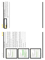
Roof orientation
Details of roof construction
Graphic display of dimensioning
Parameter enquiry
Project data
Entering site data
8_Programme
Then you have to select between Beam roof and Rafter roof for the roof construction. The flat roof presents a special case, described in the next section.
After the selection of the roof construction four fields must be completed
with details on the distances between the first and last rafter or the first and
last roof beam to the roof edge, the greatest rafter/beam distance and the
number of beams/rafters.
In Parameter specify your selection and dimension the roof. The roof measurements are entered into the fields a and bÊ>ÃÊV and d, depending on the
ÃiiVÌi`ÊÀv®ÊÊViÌiÌÀiðÊ9ÕÊÃiiÊÜ
V
ÊiÌÌiÀÊi>ÃÊÜ
V
Êi>ÃÕÀiiÌÊ
in the illustration at the left bottom of the screen. By clicking on the ? icon
next to the entry box, you can view a more detailed illustration of the measurement to be entered. The field Roof height needs the entry of the height
of the gable from the ground, whereas you enter the angle between the
ÀâÌ>Ê>`ÊÌ
iÊÀvÊÃÕÀv>ViÊÊ`i}ÀiiîÊÊÌ
iÊvi`ÊRoof slope. The next
window requires the OrientationÊvÊÌ
iÊÃÞÃÌi]ÊÜ
iÀiÊäcÊÃÊ ÀÌ
]ÊäcÊ>ÃÌ]Ê
£näcÊ-ÕÌ
Ê>`ÊÓÇäcÊ7iÃÌ°ÊvÊÌ
iÊÀi>ÊÀvÊÃÊÀiÌi`ÊÌÊ Êxc]ÊÞÕÊÕÃÌÊiÌiÀÊ
Ì
iÊÛ>ÕiÊvÊÎÈxÊÌÊ/,- °ÊÀÊ>ÊÀiÌ>ÌÊvÊ«ÀiVÃiÞÊ-ÕÌ
7iÃÌ]Ê
the value is 225 etc.
The section Parameter Enquiry is for data relating to the project. First you
must select the roof shape. To see the names of the icons, simply drag the
mouse cursor on an icon. There are Ridged roof, Monopitch roof, Hipped
roof, Half-hipped roof and Flat roof; the option Flat roof must be selected for
>Ê«ÀiVÌÃÊÌÊLiÊÃÌ>i`ÊÊ
ÀâÌ>ÊÃÕÀv>ViÃÊÕ«ÊÌÊxc®°
Parameter Enquiry
iÀiÊÞÕÊV>ÊiÌiÀÊÌ
iÊ`>Ì>ÊvÊÌ
iÊÀiëiVÌÛiÊ«ÀiVÌ°ÊV>ÌiÊ>Ê>iÊÌÊi>V
Ê
project in Project name, and enter the customer’s Address, Title, Name, First
name, Address, Contact data into the other fields.
Project Data
North German Plain: If the project is planed for the North German Plain, tick
this box due to special static calculations.
>Û}Ê iÌiÀi`Ê Ì
iÃiÊ «>À>iÌiÀÃ]Ê VÌÕiÊ ÜÌ
Ê Ì
iÊ iÌÀÞÊ vÊ Ì
iÊ «ÀiVÌÊ
data.
Selecting the fastening
Selection of support
Setup of stand-system
Optimum orientation of the modules
Designing a flat roof project
The field Support type is only relevant for the triangle support and otherwise
>VÌÛi°Ê/
iÊ>}iÊvÊÌ
iÊÃÕ««ÀÌÊV>ÊLiÊÃiiVÌi`Ê>ÃÊÓäc]ÊÎäcÊÀÊviÝLi°Ê/
iÊ
field Fastening defines how the system is to be attached to the roof. Then you
can select the Carrier profile. The option Additional load is a special feature.
iÀiÊÞÕÊV>ÊiÌiÀÊÌ
iÊ>``Ì>Ê>`ÊvÊÌ
À`«>ÀÌÞÊvÝ}Ê>ÌiÀ>ðÊ7
iÊ
this option is selected and third-party fixing materials are used, it is essential
to note the guarantee terms of TRI-STAND!
All mounting systems are available in Alu unpainted or Alu black.
Depending on the selected roof shape, there are different stand-systems to
select from. In the case of ridged, monopitch, hipped and half-hipped roofs,
the standard mounting system is Clip system or Insertion system. If the roof
ëiÊ`iÃÊÌÊiÝVii`Ê>Ê>}iÊvÊÓäc]Ê>Ì
iÀÊ«ÌÊÃÊÌ
iÊTriangle installation, in order to construct the optimum angle.
Stand-system
The next step is the selection of the roof construction type. The selection of
Concrete roof does not require additional details, whereas Rafter roof or
beam roof requires additional details regarding first and last beams /rafters,
Ì
iÀÊÕLiÀÊ>`Ê`ÃÌ>Vi°Ê7
iÊÃiiVÌ}ÊÌ
iÊv>ÌÊÀv]ÊÞÕÊV>Ê>ÃÊiÌiÀÊ>Ê
>}iÊvÊëiÊvÊÕ«ÊÌÊxc°ÊVÌÛ>Ì}ÊÌ
iÊV
iVÊLÝÊParallel to eaves calculates
the orientation of the modules in parallel to the eaves. If this option is not seiVÌi`]ÊÌ
iÊ«ÌÕÊÀiÌ>ÌÊvÊÌ
iÊ`ÕiÃÊÌÊÌ
iÊÃÕÊÃÊV>VÕ>Ìi`Ê£näc®°
7
iÊ >Ê v>ÌÊ ÀvÊ ÃÞÃÌiÊ ÃÊ `iÃ}i`]Ê Ê >``ÌÊ ÌÊ Ì
iÊ ÀvÊ `iÃÃ]Ê
height, orientation and slope, other details must be entered. If you select
chamfered in the field Eaves area another field pops up requiring the entry
of the degree of slope. If the selection is With parapet the roof parapet
height must be entered.
Programme_9
Module type selection
Module selection
Entry of number of degrees and gravel height for
upright support with flexible angle
Selecting upright or triangle support
Selecting the rail connection
10_Graphic Design
The first step of the graphic design is the selection of the desired modules.
iÀiÊ ÞÕÊ V>Ê ÃiiVÌÊ LiÌÜiiÊ ÌÜÊ `>Ì>Ê L>ÃiÃÊ >`Ê Ì
iÊ "«ÌÊ Proprietary
module. The data base General modules contains a wide variety of available
modules; the data base Tritec modules contains the modules of the current
TRITEC range. The following section describes how to create a proprietary
module. To select a module of a data base, select first the data base, then the
manufacturer of the desired module and finally the module type. The lower
part of the window shows all data the selected module features regarding
the respective project. Alternatively, you can select modules by the criterion
Cell technology, selecting the desired technology in the drop-down field.
PV Module Selection
GRAPHIC DESIGN
If the system is to be mounted on a flat roof, select the Stand-system: Upright
installation or Triangle installation. Both versions are available in Alu unpainted
or Alu black°Ê7Ì
ÊÌ
iÊÕ«À}
ÌÊÃÕ««ÀÌÊÞÕÊV>ÊÃiiVÌÊLiÌÜiiÊ>}iÃÊvÊ20°
or 30°, with the triangle support angles of 20°, 30° or Flexible. If Flexible is
selected, another text box appears where you must enter the desired number
of degrees. In addition, this selection requires the entry of the height of gravel in the field Height of gravel in cm. All other details are the same as the ones
for creating a project, with insertion or clip systems and as described above.
Then in a graphic display you can select the Standard carrier profile UP or the
Strengthened carrier profile UP-S. In the last two fields of the stand-system
selection process, you must select the connection of hooks and rails. Depending
on your selection in the field Fastening, the field Connection hooks might not
be active.
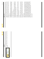
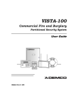
Roof with four restricted areas
Restricted area with X=150 and Y=370
Characteristics of the restricted area
Creation of proprietary modules
To edit or delete a restricted area, select it by double-clicking on it. Now you
can move it across the roof by simply Dragging & Dropping or edit it by rightclicking on it. Since several objects can be selected at the same time, the
option to edit always applies to all selected restricted areas.
For each restricted area to be added the above process must be repeated.
To keep track of things with several restricted areas, we recommend entering
a name for each restricted area in the field Name. If the option Show image
of interfering object is inactive, it is not displayed in the graphic, but blocked
for the placement of modules.
The creation of a restricted area always begins with clicking on Add restricted
area. In the now appearing window enter the dimensions of the restricted
area. As described above, information on the individual details can be displayed on the bottom left of the screen or by clicking on the ? icon. You place
the restricted area by using the options Start X and Start Y or later using the
dialogue by means of the Drag & Drop feature. If you enter for example for
Start X the value 150 cm and for Start Y the value 370 cm, the software will
create a restricted area beginning 1.5 m from the left and 3.7 m from the lower
edge of the roof. This is the point of the lower left corner of the restricted
area, which continues with the stated dimensions.
7
iÊÌ
iÊ`ÕiÊ
>ÃÊLiiÊÃiiVÌi`]ÊÞÕÊV>ÊVÀi>ÌiÊ>ÞÊÕLiÀÊvÊÀiÃÌÀVÌi`Ê
areas on the roof. These can be either real obstacles, such as chimneys,
dormers or aerials, or areas where no module should be installed, for example in order to keep maintenance paths clear.
Adding Restricted Areas
To create and use a proprietary module select the option Proprietary module
in the line Data bases. The following dialogue requires details of the module,
describing its dimensions, output, technology and installation features. Only
when all entries have been made completely and correctly, the design of the
system can continue.
Graphic Design_11
Zoom out/in
Cover whole roof symmetrically with
PV modules in portrait format
Shift left
Adding the entered number
Roof covered with modules
Features of the module field
12_Graphic Design
Right-click on empty roof area
/
ÃÊvi>ÌÕÀiÊ>ÜÃÊÞÕÊÌÊâÊÌ
iÊ}À>«
VÊ`ë>ÞÊÊÀÊÕÌÊÀÊÌÊâÊ>Ê
picture detail in or out.
By clicking on this icon the still free roof areas are covered symmetrically with
modules in the desired format.
This feature lets you move shift one or more modules in the desired direction.
Select the desired modules by double-clicking on one or by drawing a frame
around several modules. Now you can move them in the desired direction.
After selecting a module by double-clicking it, you can add another module
using the appropriate buttons on the left, right, top or bottom. Entering the
desired number into the field above the buttons, you can add several modules at the same time.
Buttons for editing the module fields
Another way to cover the roof or edit a module field is to use the buttons at
the left edge of the screen. Depending on the selected module and entered
project data, they can be used. Options that are not available can only be seen
in outlines. The top two icon rows offer the possibility to expand existing
modules and module fields; the icons of the bottom row allow the roof to be
covered completely or to adjust the view to the graphic display. All buttons
have mouseovers describing their function. Inactive buttons are shaded grey.
In the bottom section of the window you can select whether the modules are
placed in Portrait or Landscape format. In addition, you can set a minimum
distance of the module field to the roof edges. Depending on the used module,
some applications may be impossible and their corresponding fields inactive.
This way you can create as many individual module fields as to cover the roof
completely, optimally and as required.
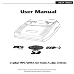
BOM of a completed project
Completely covered roof
Right-click on a solar module
Right-click on a restricted area
In addition to the above basic features of the graphic design, you can call
up additional options by right-clicking on the respective modules, restricted
areas or roof areas.
You can cover the roof with solar modules, either by using the buttons on the
left of the screen or a separate window.
Clicking on Add module field opens a window to enter all parameters required
to cover the roof with solar modules. If the roof is to be covered completely,
select the option Cover whole roof in the window’s fifth line. If only a certain
area is to be covered with modules, enter the Number of columns and Number
of rows by selecting the first check box or alternatively enter the Number of
PV modules or the desired Output.
The next section determines how the modules are to be placed on the roof.
To do this enter Start X and Start Y, where the edge of the module field is
iÌiÀi`ÊÊ8Ê>`Ê9Ê`ÀiVÌ]ÊÀÊÃiiVÌÊ>ÊVÀiÀÊvÊÌ
iÊÀvÊÌÊÜ
V
ÊÌ
iÊÃvÌware aligns the modules.
Now the BOM of all modules and installation components for the project is
created. It can be viewed as an overview and control option. It can be printed
out in the next step and forwarded to TRITEC using the Export feature. The
chapter on Export CSV-Format describes the process of exporting and submitting the data.
Current Bill of Materials
Right-clicking on a solar module can select the module or show the Module
grid. The module grid shows the complete design of the field with modules
>ÃÊvÊÊÀiÃÌÀVÌi`Ê>Ài>ÃÊiÝÃÌi`°ÊÊ>``Ì]ÊLÞÊÀ}
ÌVV}ÊÊ>Ê`ÕiÊÕÃÌÊ
>ÃÊÜÌ
ÊÌ
iÊÀiÃÌÀVÌi`Ê>Ài>îÊÞÕÊV>ÊShow coordinates or Hide coordinates
and set the Origin at the respective module.
7
iÊÞÕÊÀ}
ÌVVÊÊ>ÊÀiÃÌÀVÌi`Ê>Ài>]ÊÞÕÊV>ÊÃiiVÌÊÌ
iÊ«ÌÊÌÊSelect
restricted area, Feature or Show or Hide coordinates. Furthermore, you can
set the origin of the design at a restricted area by clicking on Coordinate >
Set origin.
By right-clicking of the empty roof you can Add in portrait format or Add in
landscape format. Under Edit you can Re-calculate statics. Zoom allows you
to zoom in, zoom out or make the image Page width. View allows you to
switch between Levels, Stand-system view and Module view. Additionally,
you can show or hide Load zones, display a mouseover with Coordinate and
show or hide a Grid.
Other Options of the Graphic Design
Add Modules
Graphic Design_13
BOM export in the window Printout Export
Exporting the BOM using the menu bar
Selected pages in print preview
Setting the print options
14_Graphic Design
Now you can send the created and saved CSV file via e-mail.
Alternatively to using the menu bar, you can create the file under Printout
Export. The lower part of the window shows the category Export BOM. By
clicking on Export you open a window to enter the location for the file to be
Ã>Ûi`ÊÌ°Ê>Û}ÊÃiiVÌi`ÊÌ
iÊÃ>ÛiÊV>ÌÊ>`Ê>}ÊÌ
iÊvi]ÊÞÕÊV>ÊiÝport and save it by clicking on Save.
To export the created BOM in CSV format select the button TRI-DESIGN BOM
under File > Export. The now appearing window allows you to select the save
location and the name of the file to be created. Clicking on Save the file is
created and the window is closed.
Export in CSV Format
By clicking on Print preview you can display a preview of the selected items.
Changing the view
Opening the manual
Selecting the programme language
Entering the designer data
To open the software manual click on Manual in the menu Help of the menu
L>À°Ê7
iÊÞÕÊ
>ÛiÊÃiiVÌi`ÊÞÕÀÊ>}Õ>}i]ÊÌ
iÊ>Õ>ÊÜÊ«i°
The software and its help file can be displayed in five languages. To select the
software language click on Languages under Settings in the menu bar. You
can choose between German, English, Spanish, French and Italian.
Enter the designer data under Settings > Designer data. They are shown in the
printout of the project. In the case of several designers in one company,
entering the editor here can show which project was edited by whom.
In addition to details of the company, you can also integrate a company logo.
Clicking on Browse under the heading Company logo you can select and add
the company logo.
The last step Printout Export lets you print out and export the project file. The
export of the BOM is described in detail in the following chapter.
Selection printouts allows you to activate all desired printouts. Activate /
deactivate lets you activate or deactivate all options at the same time.
The selection between Cover sheet, Summary, Roof drawing, Roof attachment points, Rails, Profile positions, Technical drawing, Dimensioning and Bill
of materials can now be printed by clicking on Print.
Other Features
The basic settings of the programme can be defined using the menu bar.
In addition to the already described options such as Open, Save, Print and
Export, you can switch between the seven main items of the programme
under View.
Print-out
Graphic Design_15
Force programme download
File download completed
No update necessary
16_Data Bases & Update
You can at any time cancel the update and return to the normal software
screen by clicking on Close.
7
iÊÕÃ}Ê>Ê«ÀÝÞÊÃiÀÛiÀ]ÊVVÊÊProxy. You can make all proxy settings in
the opening window.
The programme section Software Update offers two additional options.
Clicking on Force programme download downloads the latest software
version from the server, independent of the current version. This option may
become necessary if an error occurred during the last download and the
update could not be installed correctly.
If the installed and the latest available version are not identical, you will see
the message “Your version is obsolete”. In order to continue working comfortably with the TRI-DESIGN software, you should now update the software.
To start this process click on OK. Depending on your Internet connection,
`Ü>`}ÊÌ
iÊÀiµÕÀi`ÊviÃÊ>ÞÊÌ>iÊÃiÊÌi°Ê7
iÊÌ
iÊ`Ü>`ÊvÊ
all data has been successfully completed, the installation of the update must
LiÊVvÀi`ÊÊÌ
iÊ>««i>À}ÊÜ`Ü°Ê/
iÊÃÌ>>ÌÊ7â>À`ÊÜÊ}Õ`iÊ
you through the update installation, which is identical to the first installation
vÊÌ
iÊ«À}À>iÊÃiiÊ>LÛi®°
To keep the software up to date, we recommend to update it regularly. Click
on Help > Internet Update to check for new software versions and install
updates. The now opening window shows the currently installed software
version and the latest available update version. To check for available updates
and install any available ones, the computer must be connected to the Internet.
If the message “Your version is up to date” appears, no new versions of the
software and thus no updates are available.
Software Update
DATA BASES & UPDATE
Updating the programme and data base
via Help > Internet Update
The programme’s module data base is automatically updated each time the
software is updated. By regularly updating the software therefore, not only
the programme, but also the content of the data bases is kept up to date. This
way new modules can be loaded and used in the TRI-DESIGN software quickly
and easily. The process of updating the software is described in the previous
chapter.
Updating the Module Data Base
Data Bases & Update_17
Opening the contact data
18_Contact
Please read the terms of this licence agreement carefully before using the product. The product
contains software that TRITEC makes available to use free of charge exclusively to you as a
customer.
The following agreement is a legally binding agreement between you, the user, and TRITEC,
the publisher. By installing the software you agree to the following terms of use. If you do
not agree to the terms of this agreement, please do not use the software and remove it from
your computer.
To contact TRITEC directly, click on How to find us in the menu help of the
menu bar. The opening PDF file has all contact data you need to reach your
contact.
TRITEC, November 2009
© All rights reserved.
5. Limitation of liability
TRITEC is not liable for any direct or indirect losses or consequential losses, including, but not
limited to, loss of profit, not realised cost savings, incorrect calculations, loss of data or
increased costs of the user or any other financial losses, the granting of rights of use, the use,
the malfunction of the software or disruptions while running the software. The above
limitation of liability applies also if the publisher has been informed of the possible occurrence of any such loss. TRITEC is only liable for losses and damages, if the company is guilty
of intention and gross negligence. This limitation of liability applies to all damages claims,
irrespective of their legal basis, including, but not limited to, contractual, pre-contractual
contract-similar claims and claims arising from torts. This limitation of liability also applies to
all executive and non-executive employees of TRITEC and all representatives and agents of
TRITEC engaged in the development, marketing or delivery of the software. It is the sole
responsibility of the user to ensure that he himself and his employees have the required
knowledge to install and use the software correctly. TRITEC is not liable for problems and
damages arising from the insufficient knowledge of the software users.
4. Guarantee
The publisher does not guarantee that the software is free from defects, runs without
disruption, meets the expectations of the user and is suitable for certain user purposes or
does not breach the rights of third parties. The programme is designed to assist in the design
and does not replace detailed planning. The identified system configuration is only one
possible model, the calculation results represent only a projection. Subject to technical
changes and errors.
3. Data bases
The solar module and mounting system data bases used in this software have been checked
ÜÌ
ÊÌ
iÊ}Ài>ÌiÃÌÊ«ÃÃLiÊV>ÀiÊ>`Ê>ÀiÊÕ«`>Ìi`Ê>`Ê>`ÕÃÌi`ÊvÊiViÃÃ>ÀÞ°ÊÜiÛiÀ]Ê`ÃVÀi«ancies and mistakes cannot be excluded. Therefore, no guarantee as to the correctness and
completeness of the used data is given.
2. Reservation of intellectual property rights
Notwithstanding any changes or adjustments made by you or for you, the programme, the
programme documentation and any parts thereof, all copyrights, patents and other inteliVÌÕ>ÊÀ}
ÌÃÊVÌ>i`ÊÌ
iÀiÊÃ
>ÊÀi>ÊÌ
iÊ>LÃÕÌiÊ«À«iÀÌÞÊvÊ/,/
°ÊiÀiLÞÊÞÕÊ
confirm that you do not have any other rights in the programme or its programme documentation than the rights explicitly granted in this agreement.
1. Copies and distribution
The TRI-DESIGN software was developed for TRITEC and is protected by copyright. Copying
the programme is only allowed for data backup purposes. Copies of the programme documentation are prohibited. Transferring, renting, leasing or otherwise making the programme
or the programme documentation available to third parties is not allowed without the
previous written consent of TRITEC.
TERMS OF USE
CONTACT
Terms of Use_19
www.tritec-energy.com