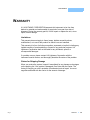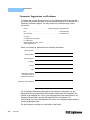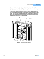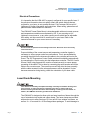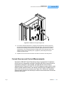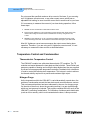
1
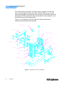
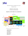
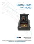
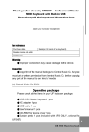
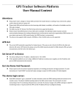
User’s Guide Laser Diode Mount LDM-4407 ILX Lightwave Corporation · 31950 Frontage Road · Bozeman, MT, U.S.A. 59715 · U.S. & Canada: 1-800-459-9459 · International Inquiries: 406-556-2481 · Fax 406-586-9405 ilx.custhelp.com · www.ilxlightwave.com 70002803 May 2011 TA B L E O F C O N T E N T S TABLE OF CONTENTS Table of Contents . . . . . . . . . . . . . . . . . . . . . . . . . . . . . . . . . . . . . . . . . . . i List of Figures and Tables . . . . . . . . . . . . . . . . . . . . . . . . . . . . . . . . . . . iii Safety and Warranty Information . . . . . . . . . . . . . . . . . . . . . . . . . . . . . . v Safety Information and the Manual . . . . . . . . . . . . . . . . . . . . . . . . . . . . . . . . . v General Safety Considerations . . . . . . . . . . . . . . . . . . . . . . . . . . . . . . . . . . . . v Safety Symbols . . . . . . . . . . . . . . . . . . . . . . . . . . . . . . . . . . . . . . . . . . . . vi Safety Marking Symbols . . . . . . . . . . . . . . . . . . . . . . . . . . . . . . . . . . . . . . . . . vi Warranty . . . . . . . . . . . . . . . . . . . . . . . . . . . . . . . . . . . . . . . . . . . . . . . . . . vii Comments, Suggestions, and Problems . . . . . . . . . . . . . . . . . . . . . . . . . . . viii Chapter 1 Introduction Product Overview . . . . . . . . . . . . . . . . . . . . . . . . . . . . . . . . . . . . . . . . . . . . . . . . 1 Specifications . . . . . . . . . . . . . . . . . . . . . . . . . . . . . . . . . . . . . . . . . . . . . . . . . . . 3 Chapter 2 Operation Disassembly . . . . . . . . . . . . . . . . . . . . . . . . . . . . . . . . . . . . . . . . . . . . . . . . . . . . 5 Electrical Connections . . . . . . . . . . . . . . . . . . . . . . . . . . . . . . . . . . . . . . . . . . . . 6 Laser Grounding Considerations . . . . . . . . . . . . . . . . . . . . . . . . . . . . . . . . . . 8 Electrical Precautions . . . . . . . . . . . . . . . . . . . . . . . . . . . . . . . . . . . . . . . . . . . 9 Laser Diode Mounting . . . . . . . . . . . . . . . . . . . . . . . . . . . . . . . . . . . . . . . . . . . . . 9 Current Sources and Current Measurements . . . . . . . . . . . . . . . . . . . . . . . . . 11 05_11 LDM-4407 i TA B L E O F C O N T E N T S Temperature Control and Condensation . . . . . . . . . . . . . . . . . . . . . . . . . . . . . 12 Thermoelectric Temperature Control . . . . . . . . . . . . . . . . . . . . . . . . . . . . . . 12 Nitrogen Purge . . . . . . . . . . . . . . . . . . . . . . . . . . . . . . . . . . . . . . . . . . . . . . . 12 Chapter 3 ii LDM-4407 Safety L I S T O F F I G U R E S A N D TA B L E S LIST OF FIGURES AND TABLES Figure 1.1 Exploded View of the LDM-4407 . . . . . . . . . . . . . . . . . . . . 2 Figure 2.1 4407 PCB Showing Switch Settings . . . . . . . . . . . . . . . . . 7 Figure 2.2 Installation of a 5.6 mm Window Can Laser . . . . . . . . . . 10 Figure 2.3 Installation of a Large Flanged Laser . . . . . . . . . . . . . . . 11 Figure 2.4 LDM-4407 Laser Cable Pinouts . . . . . . . . . . . . . . . . . . . 13 Figure 2.5 LDM-4407 TE Module Cable Pinouts . . . . . . . . . . . . . . . 13 Table 2.1 11Switch Settings for Common Laser Configurations 05_11 LDM-4407 iii L I S T O F F I G U R E S A N D TA B L E S iv LDM-4407 SAFETY AND WARRANTY INFORMATION The Safety and Warranty Information section provides details about cautionary symbols used in the manual, safety markings used on the instrument, and information about the Warranty including Customer Service contact information. Safety Information and the Manual Throughout this manual, you will see the words Caution and Warning indicating potentially dangerous or hazardous situations which, if not avoided, could result in death, serious or minor injury, or damage to the product. Specifically: Caution indicates a potentially hazardous situation which can result in minor or moderate injury or damage to the product or equipment. Warning indicates a potentially dangerous situation which can result in serious injury or death. WARNING Visible and/or invisible laser radiation. Avoid direct exposure to the beam. General Safety Considerations If any of the following conditions exist, or are even suspected, do not use the system until safe operation can be verified by trained service personnel: • Visible damage • Severe transport stress • Prolonged storage under adverse conditions • Failure to perform intended measurements or functions If necessary, contact ILX Lightwave or the authorized local ILX Lightwave distributor, for information on how the appropriate system components should be removed and sent back to ILX for servicing. (see the contact information on page viii). All components returned to ILX Lightwave are required to have a Return Authorization Number assigned by an official representative of ILX Lightwave Corporation. See Claims for Shipping Damage on page vii for more information. LDM-4407 v SAFETY SYMBOLS SAFETY SYMBOLS This section describes the safety symbols and classifications. Technical specifications including electrical ratings and weight are included within the manual. See the Table of Contents to locate the specifications and other product information. The following classifications are standard across all ILX Lightwave products: • Indoor use only • Ordinary Protection: This product is NOT protected against the harmful ingress of moisture. • Class I Equipment (grounded type) • Mains supply voltage fluctuations are not to exceed ±10% of the nominal supply voltage. • Pollution Degree II • Installation (overvoltage) Category II for transient overvoltages • Maximum Relative Humidity: <80% RH, non-condensing • Operating temperature range of 0 °C to 28 °C • Storage and transportation temperature of –40 °C to 70 °C • Maximum altitude: 3000 m (9843 ft.) • This equipment is suitable for continuous operation. Safety Marking Symbols This section provides a description of the safety marking symbols that appear on the instrument. These symbols provide information about potentially dangerous situations which can result in death, injury, or damage to the instrument and other components. Caution, refer to manual Earth ground Terminal Alternating current Visible and/or invisible laser radiation Caution, risk of electric shock Protective Conductor Terminal Caution, hot surface Frame or chassis Terminal On: In position of a bistable push control. The slash (I) only denotes that mains are on. or (I) vi LDM-4407 Off: Out position of a bistable push control. The circle (O) only denotes that mains are off. or (O) WA R R A N T Y WARRANTY ILX LIGHTWAVE CORPORATION warrants this instrument to be free from defects in material and workmanship for a period of one year from date of shipment. During the warranty period, ILX will repair or replace the unit, at our option, without charge. Limitations This warranty does not apply to fuses, lamps, defects caused by abuse, modifications, or to use of the product for which it was not intended. This warranty is in lieu of all other warranties, expressed or implied, including any implied warranty of merchantability or fitness for any particular purpose. ILX Lightwave Corporation shall not be liable for any incidental, special, or consequential damages. If a problem occurs, please contact ILX Lightwave Corporation with the instrument's serial number, and thoroughly describe the nature of the problem. Claims for Shipping Damage When you receive the system, inspect it immediately for any damage or shortages on the packing list. If the system is damaged, file a claim with the carrier. The factory will supply you with a quotation for estimated costs of repair. You must negotiate and settle with the carrier for the amount of damage. 05_11 LDM-4407 vii WA R R A N T Y Comments, Suggestions, and Problems To ensure that you get the most out of your ILX Lightwave product, we ask that you direct any product operation or service related questions or comments to ILX Lightwave Customer Support. You may contact us in whatever way is most convenient: Phone . . . . . . . . . . . . . . . . . . . . . . . . . . . (800) 459-9459 or (406) 586-1244 Fax . . . . . . . . . . . . . . . . . . . . . . . . . . . . . . . . . . . . . . . . . . . . . (406) 586-9405 On the web at: . . . . . . . . . . . . . . . . . . . . . . . . . . . . . . . . . . . . ilx.custhelp.com Or mail to: ILX Lightwave Corporation P. O. Box 6310 Bozeman, Montana, U.S.A 59771 www.ilxlightwave.com When you contact us, please have the following information: Model Number: Serial Number: End-user Name: Company: Phone: Fax: Description of what is connected to the ILX Lightwave instrument: Description of the problem: If ILX Lightwave determines that a return to the factory is necessary, you will beissued a Return Authorization (RA) number. Please mark this number on the outside of the shipping box. You or your shipping service are responsible for any shipping damage when returning the instrument to ILX Lightwave; ILX recommends you insure the shipment. Be sure to use enough packing material to prevent shipping damage. We look forward to serving you even better in the future! viii LDM-4407 CHAPTER 1 INTRODUCTION This manual describes the LDM-4407 Laser Diode Mount and explains its operation. Information is also provided to assist in customizing this mount to satisfy specific laser mounting needs. This chapter provides an overview of the LDM-4407 Laser Diode Mount, and contains general information and specifications important in its use. Product Overview The LDM-4407 is a temperature controlled laser diode mount which allows easy fixturing for many of today’s popular can-package lasers. It allows for precise temperature control of the laser package. The mount provides two laser clamps which allow quick mounting of either 5.6 mm or 9.0 mm flanged lasers. The mount’s base has been designed to allow easy integration into experiments on either English or Metric optical breadboards. The LDM-4407 allows direct interfacing to most of ILX’s current sources and temperature controllers through standard ILX cables. This gives you the flexibility to select the proper current source or temperature controller for your particular application. Additional flexibility is provided by allowing easy reconfiguration of the mountto match the pinouts found in common laser diode packages. The LDM-4407 is intended for applications where a can-type laser diode needs to be tested under a controlled environment and for applications which require direct access to the laser window for collimation or optical coupling. For example, the 4407 would aid in experiments that measure optical power output from a laser as a function of case or die temperature and/or laser drive current. The LDM-4407 consists of a base, heat sink, laser plate and clamps, thermoelectric modules, PCB assembly, and front and rear covers (see Figure 1.1). The mountincludes a mini banana jack for a wrist strap or grounding wire, as well as a fitting which allows the user to purge the laser chamber with nitrogen. A plastic nozzle is snap fit into the front cover, and provides for maximum nitrogen LDM-4407 1 CHAPTER INTRODUCTION Product Overview 1 flow across the front of the laser. The nozzle may be snapped out of the front cover to provide greater access to the laser, if desired. The rear cover can be easily removed to allow reconfiguration of the mount for different laser pinouts. the laser plate and PCB assembly are factory assembled for correct alignment, and should not be removed or disassembled. Figure 1.1 is an exploded view of the LDM-4407 which identifies major components and illustrates their assembly. MOUNTING S CRE WS - M6 REA R COV ER THERMOE LECTRIC MODULES LASER P LATE CALIB RATI ON DA TA LAS ER CLAM P LAB EL FRONT COVE R PCB ASSE MBLY NOZZLE HEA T S INK NITROGEN FITTI NG GROUNDING T ERMINA L BA SE Figure 1.1 Exploded View of the LDM-4407 2 LDM-4407 INTRODUCTION Specifications CHAPTER 1 Specifications Laser Packages Supported 5.6 mm, 9 mm, flanged Optical Beam Height 80 mm Position Repeatability < 200 m Angular Repeatability <10 mrad Input Connectors Current Source 9-pin D-Sub, female Temperature Controller 9-pin D-Sub, male Nitrogen Purge Brass barbed fitting for 1/16” ID tubing Ground Miniature banana jack Temperature Control Range 1 0 to 70 oC Sensor Type 10k @ 25oC calibrated Temperature Response Time (0oC to 25oC)2 120 seconds TE Module Ratings Qmax 28W (2 @ 14W each) Tmax 70oC Imax 6.0 A Vmax 8.0 V General Size (H x W x D) 1.4” x 4.3” x 3.7”; 36mm x 110mm x 95mm Weight 1.2 pounds; 0.56 kg. 1. Air cooled mount operating at 25oC ambient. 2. Stabilized to within +0.2oC of the setpoint using a 4A driver. Our goal is to make the best laser diode instrumentation available anywhere. To achieve this, we need your ideas and comments on ways we can improve out products. We invite you to contact us at any time with your suggestions. 05_11 LDM-4407 3 CHAPTER 4 LDM-4407 1 INTRODUCTION Specifications CHAPTER 2 OPERATION The LDM-4407 is shipped from the factory with no configuration set for the laser pin-out. Operation of your laser will be impossible without first configuring the LDM-4407. Before installing your laser, please read the sections in this chapter for details on how to do this. This chapter describes the electrical connection and mounting of laser diodes. Configuration options for the LDM-4407 and its various laser package mounting schemes are also discussed. Disassembly The LDM-4407 is easily disassembled for access to the PCB switches by removing the rear cover. This is accomplished by removing the four connector studs with a 3/16” nut driver (see Figure 1.1). Then slide the rear cover straight off the back of the mount, clearing the PC board connectors. Unless you want to provide earth grounding to your laser, no further disassembly of the rear portion of the mount should be performed. For details on laser grounding, please refer to the section titled Laser Grounding on page 8. To reassemble the mount, reverse the above procedure. Access to the front of the LDM-4407 for laser installation and removal is obtained by removing the two button head screws with a 2 mm hex key wrench (included in the LDM-4407 accessory kit). After removing the front cover, the laser clamp can be removed by loosening the two socket head cap screws with a 1.5 mm hex key wrench (also included in the accessory kit) Note: The laser plate is factory aligned with the heat sink and thermoelectric modules, and should not be removed or adjusted. The base of the LDM-4407 can also be removed to reduce the beam height or to mount the heat sink assembly onto an optical rail carrier. Note that the heat sink LDM-4407 5 CHAPTER 2 OPERATION Electrical Connections assembly can only be directly mounted onto a metric carrier, since the bolt spacing is 50 mm. To remove the base, simply remove the rear cover (as described above) and loosen the two M6 sock head cap screws using a 5 mm hex key wrench (not included). Electrical Connections Laser diodes are extremely susceptible to damage caused by electrostatic discharge and surge currents. To avoid early failure or damage to the device, workers and work benches must be grounded at all times when handling or working with laser diodes. The LDM-4407, as shipped from the factory, is not configured for any laser. Therefore, the mount must be configured for your particular laser before operation. To access the configuration switches, you must remove the rear cover as described above. Table 2.1 indicates the pin-outs for common laser configurations. Compare these to the pin assignment information given on the data sheet of the particular laser you are using. If the pin-outs are identical to a laser listed, you may reconfigure the mount using the switch settings for that laser. Amongst manufacturers there is no standard procedure for numbering of the laser pins. Therefore, we have adopted a somewhat generic scheme which coincides with most packages: • View the laser package from the rear or leaded side. • Pin 1 is identified as the left pin when the package is oriented with the indexing notch up. • Pin 2 is the topmost pin, pin 3 and pin 4 are numbered in clockwise order. As shown in Figure 2.1, the DIP switches are numbered in the same order as the laser pins. If the pin-outs on your laser do not match a laser listed in Table 2.1, then the switch settings can easily be determined from your laser data sheet. Referring to Figure 2.1, each position of the DIP switch corresponds to a laser function. Position 1 is laser anode; Position 2 is laser cathode; Position 3 is photodiode anode; Position 4 is photodiode cathode. Each switch can independently connect its laser pin to laser anode, laser cathode, photodiode anode, and photodiode cathode by simply selecting the corresponding switch position. Figure 2.1 shows the switch settings for a three pin laser with common laser cathode and photodiode cathode. From Table 2.1, this three pin laser has the following pin-outs: Pin 1 is laser anode, LA; Pin 2 is a common laser cathode, LC, and photodiode cathode, PC; Pin 3 is photodiode anode, PA. Therefore, from the 6 LDM-4407 OPERATION Electrical Connections CHAPTER 2 figure, Switch 1 has the LA position on, Switch 2 has both the LC and PC positions on, and Switch 3 has the PA position on. Note that since this is a 3-pin laser, Switch 4 is not used, and all positions are off. The LDM-4407 can also be configured for four pin lasers. Please note that it is not recommended to have the laser and photodiode floating with respect to each other. This can create a large potential difference between the two components, which could damage them. It is suggested that you refer to your current source manual for the correct wiring for your laser diode. LASER PIN 2 GROUND JUMPER FOR LASER PIN 1 LASER PIN 1 SWITCH 1 SWITCH 2 Figure 2.1 4407 PCB Showing Switch Settings 05_11 LDM-4407 7 CHAPTER OPERATION Electrical Connections 2 Table 2.1 Switch Settings for Common Laser Configurations Pin Configuration Switch Settings (Positions Listed are On) 1 2 3 4 1 2 3 4 LC LA/PC PA none 2 1,4 3 none LA LC/PC PA none 1 2,4 3 none PA LA/PC LC none 3 1,4 2 none LC PA LA/PC none 2 3 1,4 none LA LC/PA PC none 1 2,3 4 none LC LA PA PC 2 1 3 4 LC PC PA LA 2 4 3 1 LA PC PA LC 1 4 3 2 LA = Laser Anode (Position 1 on each DIP switch) LC = Laser Cathode (Position 2 on each DIP switch) PA = Photodiode Anode (Position 3 on each DIP switch PC = Photodiode Cathode (Position 4 on each DIP switch) Laser Grounding As shipped from the factory, all laser pins are electrically isolated from the mount. The LDM-4407 PCB is capable of grounding any combination of the four laser pins. As shown in Figure 2.1, orientation of the grounding pad area is identical to the laser socket orientation. By soldering a 0.100” long jumper between the inner laser pad and the outer ring of ground pads, that laser pin will be effectively grounded to the mount. In order to ground a laser pin, follow these steps: 1 Disable the output from any controller connected to the mount. 2 Disconnect the controller cables from the mount. 3 Remove the rear cover as detailed earlier in this chapter. 4 Purchase or fabricate a 0.100” long by 0.100” high jumper from a 22-24 AGW solid wire. 5 Place the jumper in place and solder. Work quickly to avoid overheating the PCB pads. 6 Replace the rear cover. Additionally, the mount can be earth grounded by connecting a patch cord with a mini banana terminal to a known earth ground. The banana jack on the side of the LDM-4407 will accept miniature (0.10” diameter) plugs. 8 LDM-4407 OPERATION Laser Diode Mounting CHAPTER 2 Electrical Precautions It is imperative that the LDM-4407 is properly configured for your specific laser. If the previous information does not specify clearly the switch settings that are required for your laser, do not operate the laser. Call Customer Service at ILX Lightwave for further information and instructions. When calling, please have all pertinent laser data available for reference. The LDM-4407 Laser Diode Mount is interchangeable with most current sources and temperature controllers manufactured by ILX. If you are using an ILX Lightwave current source, or any other current source which has an adjustable limit setting, set the current limit to a safe level for your laser. Refer to the instruction manual for your current source if necessary. Do not exceed the specified current settings of the laser. Excessive drive current may cause laser failure. Proper shielding of the current source and temperature controller signals is necessary to ensure proper noise-free performance. This is accomplished by grounding the shield on the interconnect cables to the controller and not to the mount. The 505 Temperature Control Cable provides this shielding automatically by connecting the 15 pin housing into the temperature controller. The 303 Current Source Cable, being symmetrical, must be oriented correctly to ensure proper grounding of the shield. This is done by connecting the serial-number end of the cable to the current source. The current source will still drive the laser normally with the cable reversed, but the noise performance will be degraded. If noise becomes excessive during testing, check the orientation of your laser cable. Laser Diode Mounting Laser diodes are extremely susceptible to damage caused by electrostatic discharge and surge currents. To avoid early failure or damage ot the device, workers and work benches must be grounded at all times when handling or working with laser diodes. In addition, the LDM-4407 should be grounded to the workbench. The LDM-4407 is designed to allow quick and easy insertion of lasers through the use of a transistor test socket and a laser clamp. Two laser clamps are provided with each mount to allow fixturing of 5.6 mm and 9.0 mm window can lasers, as well as 11 x 16 mm and 14 x 20 mm flanged laser packages. To avoid damage to 05_11 LDM-4407 9 CHAPTER OPERATION Laser Diode Mounting 2 the laser or clamp, verify that one of the clamps provided fits your laser package before attempting installation. To mount a laser diode, refer to Figures 2.2 and 2.3, and follow these steps: 1 Ensure that the mount has been configured for the correct pin-outs for the laser you are about to install. If it has not been configured, refer to instructions earlier in this chapter for more information. 2 Disable all controllers connected to the mount, and remove the front cover by loosening the two button head screws. 3 Remove the two socket-head cap screws from the laser clamp with the 1.5 mm hex key wrench, and remove the clamp. Select the correct size clamp for you laser package. Insert the laser, with the indexing notch up, through the hole in the laser plate, and into the test socket. Ensure that the laser pins uniformly engate the socket. Then place the laser clamp over the laser package. Make sure that the clamp is parallel to the laser plate, and firmly secure the mounting screws and re-check the laser plsition. Re-adjust if necessary Note: The laser plate does not have an electrically insulating surface. Therefore, the possibility of shorting the laser pins exists. Although the possibility of this occurring with a carefully installed laser is very remote, the user may wish to take every precaution. It is recommended that insulating tubing be placed over the laser leads before installing a laser into the plate. The tubing should be thin wall and should not be more than 3.2 mm (1/8”) long. Figure 2.2 Installation of a 5.6 mm Window Can Laser 10 LDM-4407 OPERATION Current Sources and Current Measurements CHAPTER 2 Figure 2.3 Installation of a Large Flanged Laser 4 For maximum thermal performance, it is highly recommended that a thermal compound be used at the interface between the laser and the laser plate. This will maximize the heat transfer from the package, and reduce the temperature gradient produced by a metal-tometal interface. This is especially important for higher-power 9 mm packages which must dissipate a large amount of thermal power. A graphite or phase-change thermal pad material may also be used. 5 Replace the front cover and reconnect the controllers. The laser is now ready to test. Current Sources and Current Measurements Operate the LDM-4407 Laser Diode Mount using an appropriate ILX Lightwave current source or temperature controller. Operation with other current sources or temperature controllers is also possible, provided that the correct wiring is observed (refer to Figures 2.4 and 2.5). If an ILX Lightwave current source is used with the system interlock feature, the interlock connections are available at pins 1 and 2 of the current source connector (see Figure 2.4). With the ILX Lightwave interlock feature enabled, the interlock pins must be connected before current can flow from the source. 05_11 LDM-4407 11 CHAPTER OPERATION Temperature Control and Condensation 2 Do not exceed the specified maximum drive current of the laser. If you are using an ILX Lightwave current source, or any other current source which has an adjustable limit setting, be sure to set the current limit to a safe level for your laser. If it is necessary to measure the current of your laser during operation, follow these steps: 1 NEVER connect an ammeter in series with the laser circuit. 2 Place a known resistance (1 ohm works well) in series with the laser diode circuit. Then, measure the voltage across the resistor. Calculate the current by using Ohm’s Law, I = E/R. 3 NEVER turn the voltmeter on or off, or change the voltage measurement range, while current is flowing to the laser. These actions could result in damage to your laser diode. Most ILX Lightwave current sources measure the output current during laser operation. Therefore, if you are using an ILX Lightwave current source, it is not necessary to measure the laser current as described above. Temperature Control and Condensation Thermoelectric Temperature Control The LDM-4407 contains two solid-state thermoelectric (TE) modules. The TE modules are located between the laser plate and the heat sink. These Peltier heat pumps are capable of heating and cooling the laser diode when they are supplied by current from an appropriate temperature controller. Feedback from a thermistor is used to control the laser device’s temperature. This is done in order to achieve the thermal stability required for a precise and consistent light output. Nitrogen Purge As the temperature within the LDM-4407 is varied dramatically up and down, the problem of condensation around the laser device and mount becomes a concern. This environmental problem has been addressed by the use of a nitrogen purge. On the side of the mount, above the grounding terminal, is a gas nipple through which any inert gas may be injected. This process ventilates the inner cavity of the LDM-4407, preventing condensation. The infiltration of airborne particulate matter (such as dust or smoke), which could contaminate the laser, is also prevented. 12 LDM-4407 OPERATION Temperature Control and Condensation CHAPTER 2 Figure 2.4 LDM-4407 Laser Cable Pinouts Figure 2.5 LDM-4407 TE Module Cable Pinouts 05_11 LDM-4407 13 CHAPTER 14 LDM-4407 2 OPERATION Temperature Control and Condensation CHAPTER 3 SAFETY Laser diodes used with the LDM-4407 Laser Diode Mount may emit infrared radiation which is invisible to the human eye. Extreme care must be taken to prevent the beam from being viewed either directly or through external optics or mirrors. Remove rings, jewelry, and other reflective materials when working with lasers. Viewing of emissions from the fiber may cause eye damage. Use of protective goggles is recommended when operating these lasers. Use of controls or adjustments or performance of procedures other than those specified herein may result in hazardous radiation exposure. This product conforms to all applicable DHHS regulations 21 CFR Subchapter J, at the date of manufacture. LDM-4407 15 CHAPTER 16 LDM-4407 3 SAFETY