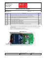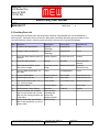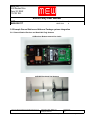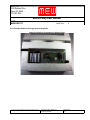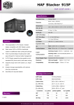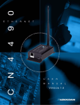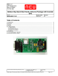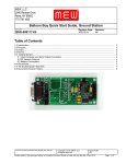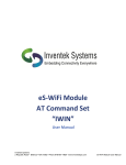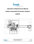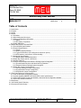
1
MEW, LLC
3040 Reuben Drive
Reno, NV 89502
775 790 1850
Balloon Boy User Manual
DOC NUM:
MAN-000117
Revision Date:
14DEC2010
Revision:
A
Table of Contents
1.0 Introduction.......................................................................................................................................................... 2
2.0 Purpose............................................................................................................................................................... 2
3.0 Scope................................................................................................................................................................... 2
4.0 Norms.................................................................................................................................................................. 3
4.1 Definitions....................................................................................................................................................... 3
4.2 Abbreviations and Acronyms.......................................................................................................................... 3
4.3 Safety and Regulatory Information................................................................................................................. 4
4.3.1 Safety:.................................................................................................................................................... 4
4.3.2 RF Agency Compliance:......................................................................................................................... 4
4.4 Quality Statement .......................................................................................................................................... 5
5.0 Balloon Boy System Technical Data.................................................................................................................... 5
5.1 Environmental Specifications:........................................................................................................................ 5
5.2 Electrical Specifications:................................................................................................................................. 6
5.2.1 Power..................................................................................................................................................... 6
5.2.2 Radio Frequency Modem....................................................................................................................... 6
5.2.3 Typical Performance (AP configured for maximum power)................................................................... 6
5.2.4 GPS features, performance, and functionality....................................................................................... 7
5.3 Mechanical Specifications.............................................................................................................................. 7
5.3.1 Board Outline and Mounting Holes........................................................................................................ 7
5.4 Balloon Boy Power and I/O connections:....................................................................................................... 9
5.5 Auxiliary Parts List ....................................................................................................................................... 11
5.6 Example Ground Station and Airborne Package systems integration......................................................... 12
5.6.1 Ground Station Receiver and Hand Held Yagi Antenna...................................................................... 12
5.6.2 Example Airborne Package system integration................................................................................... 13
5.7 Balloon Boy Jumper Configurations:............................................................................................................ 14
5.7.1 Airborne Package Jumper Configuration ............................................................................................ 14
5.7.2 Ground Station Jumper Configuration ................................................................................................. 15
5.7.3 GPS Module Jumper Configuration .................................................................................................... 16
6.0 Third Party Reference Documentation.............................................................................................................. 17
6.1 Laird Technologies configuration software:.................................................................................................. 17
6.2 Inventek Systems ISM300F2-C5-V0004 GPS module specifications:......................................................... 17
6.3 U-Blox LEA-6H GPS module specifications, documents and configuration software:................................. 17
6.4 Visual GPS Windows freeware:................................................................................................................... 17
7.0 Disclaimers........................................................................................................................................................ 17
8.0 “No Double Speak” Warranty............................................................................................................................ 18
9.0 Document Revision History............................................................................................................................... 19
C:\Users\John B\Documents\BALLOON_BOY\BB_USER_MAN_lttr.odt
Copyright © 2010, MEW, LLC
All Rights Reserved.
Approved By:
J.B.
Printed copies of this document without a Controlled Document stamp are valid until one day after 26 Nov 2010
Page 1 of 19
MEW, LLC
3040 Reuben Drive
Reno, NV 89502
775 790 1850
Balloon Boy User Manual
DOC NUM:
MAN-000117
Revision Date:
14DEC2010
Revision:
A
1.0 Introduction
Balloon Boy (BB) is the project name for the GPS tracker and telemetry system targeted for use with high altitude
balloon and rocket flights. Balloon Boy Printed Wiring Assemblies (PWAs) contain Electrostatic Discharge (ESD)
sensitive components and must be handled in a manner to prevent immediate, delayed or latent damage from
ESD. You must practice normal and customary ESD control techniques to insure a long and happy life for the BB
PWAs.
The system typically consists of at least two and optionally more systems consisting of one Airborne Package
(AP) and one or more Ground Stations (GS). The AP typically transmits digital data to one or more Ground
Stations at a rate of one update per second. This data rate can be changed by the end user through configuration
software for the respective GPS receiver on the AP.
There are three basic starting configurations for the BB hardware:
1. Balloon Boy Airborne Package using InventekTM GPS receiver technology with Laird Technologies® 900
MHz, 1 watt RF modem.
2. Balloon Boy Ground Station hardware (no GPS receiver installed and 200 mW Laird Technologies RF
modem)
3. Balloon Boy Airborne Package using U-Blox® GPS receiver technology with Laird Technologies 900 MHz,
1 watt RF modem.
2.0 Purpose
This User Manual is intended to help the end user with integrating the Balloon Boy hardware with their respective
high altitude balloon or rocket projects.
3.0 Scope
This User Manual is intended for use by end users who have a need to know the technical details necessary for
successful balloon and rocket flights and recoveries using the BB system. This manual is not all inclusive and the
author makes the assumption that the end user is completely cognizant of the various technical areas of
expertise required for system integration.
The BB hardware requires additional peripheral equipment that must be carefully chosen by the user for their
unique project requirements. Some of the additional equipment is noted in the following list:
•
•
•
•
•
Airborne Package GPS antenna and coaxial cable with associated connectors
Airborne Package RF modem antenna and coaxial cable with associated connectors
Airborne Package batteries, holders, and power switch
Ground station Antenna and RF cable assemblies with associated connectors
Ground Station batteries, holders, power switch and associated alarms or annunciators.
C:\Users\John B\Documents\BALLOON_BOY\BB_USER_MAN_lttr.odt
Copyright © 2010, MEW, LLC
All Rights Reserved.
Approved By:
J.B.
Printed copies of this document without a Controlled Document stamp are valid until one day after 26 Nov 2010
Page 2 of 19
MEW, LLC
3040 Reuben Drive
Reno, NV 89502
775 790 1850
Balloon Boy User Manual
Revision Date:
14DEC2010
DOC NUM:
MAN-000117
•
Revision:
A
Appropriate environmental protection for the AP and GS in the form of a chassis, insulation, housing or
project box.
4.0 Norms
Safety considerations and Radio Frequency (RF) compliance as referenced in this User Manual are limited in
scope to the Balloon Boy system. This section does not address other regulatory requirements of typical balloon
or rocket flights such as FAA, BLM, BATF, OSHA and all other federal, State or local agencies. Compliance and
permitting with these and any other agencies such as EU RoHS and WEEE is beyond the scope of this user
manual and must be addressed by the equipment end user(s) and/or importers.
4.1 Definitions
For definition of unfamiliar words, phrases, or terms, please utilize and donate on line to Wikipedia:
http://www.wikipedia.org/
4.2 Abbreviations and Acronyms
ISO
BB
LOS
GPS
ISM
PWA
PWB
AP
GS
FCC
RF
IC
WRT
RGA
NMEA
OS
SAR
ESD
EOS
International Organisation for Standards
Balloon Boy
Line of Sight
Global Positioning System
Industrial, Scientific, and Manufacturing
Printed Wiring Assembly
Printed Wiring Board
Airborne Package
Ground Station
Federal Communications Commission
Radio Frequency
Industry Canada
With Respect To
Return Goods Authorization
National Marine Electronics Association
Operating System
Specific Absorption Rate
Electrostatic Discharge
Electrical Over Stress
C:\Users\John B\Documents\BALLOON_BOY\BB_USER_MAN_lttr.odt
Copyright © 2010, MEW, LLC
All Rights Reserved.
Approved By:
J.B.
Printed copies of this document without a Controlled Document stamp are valid until one day after 26 Nov 2010
Page 3 of 19
MEW, LLC
3040 Reuben Drive
Reno, NV 89502
775 790 1850
Balloon Boy User Manual
Revision Date:
14DEC2010
DOC NUM:
MAN-000117
Revision:
A
4.3 Safety and Regulatory Information
4.3.1 Safety:
WARNING: This equipment has been approved for mobile applications where the equipment should be used at
distances greater than 20 cm from the human body (with the exception of hands, feet, wrists, and ankles). Operation
at distances of less than 20 cm is strictly prohibited and requires additional SAR testing.
4.3.2 RF Agency Compliance:
BB Airborne Package and Ground Station contains Laird Technology RF modem under the following FCC and
Industry Canada compliance statements/certificates:
United States of America:
Balloon Boy Airborne Package or Ground Station equipped with Laird Technologies AC4490LR-1000
Contains FCC ID: KQLAC4490
Balloon Boy Airborne Package or Ground Station equipped with Laird Technologies AC4490LR-200
Contains FCC ID: KQL-4X90200
The enclosed device complies with Part 15 of the FCC Rules. Operation is subject to the following two
conditions:
(1)
This device may not cause harmful interference, and
(2)
This device must accept any interference received, including interference
that may cause undesired operation.
Canada:
Balloon Boy Airborne Package or Ground Station equipped with Laird Technologies AC4490LR-1000
covered under IC certificate 2268C-44901000
Balloon Boy Airborne Package or Ground Station equipped with Laird Technologies AC4490LR-200
Covered under IC : certificate 2268C-4x90200
The BB system is shipped to the buyer configured such that the Airborne Package is a server in broadcast mode
(transmitter) and the Ground Station is a client in receive mode (receiver).
The above referenced certifications and approvals are valid when the BB system is used with the following
specific antennas or equivalent antennas with equal or lesser gain:
C:\Users\John B\Documents\BALLOON_BOY\BB_USER_MAN_lttr.odt
Copyright © 2010, MEW, LLC
All Rights Reserved.
Approved By:
J.B.
Printed copies of this document without a Controlled Document stamp are valid until one day after 26 Nov 2010
Page 4 of 19
MEW, LLC
3040 Reuben Drive
Reno, NV 89502
775 790 1850
Balloon Boy User Manual
Revision Date:
14DEC2010
DOC NUM:
MAN-000117
Laird Part Number
Manufacturer Part
Number
Manufacturer
Revision:
A
Type
Gain
(dBi)
0600-00019
S467FL-5-RMM915S
Nearson
1/2 Wave Dipole
2
0600-00025
S467FL-5-RMM-915 Nearson
1/2 Wave Dipole
2
0600-00024
S467AH-915
Nearson
1/2 Wave Dipole
2
0600-00027
S467AH-915R
Nearson
1/2 Wave Dipole
2
0600-00028
S161AH-915R
Nearson
1/2 Wave Dipole
2.5
0600-00029
S161AH-915
Nearson
1/2 Wave Dipole
2.5
0600-00030
S331AH-915
Nearson
1/4 Wave Dipole
1
-
Y2283*
Comtelco
Yagi
6 dBd
-
Y2283A-915-10RP
Comtelco
Yagi
6 dBd
-
SG101N915*
Nearson
Omni
5
-
SG101NT-915
Nearson
Omni
5
* Strictly requires professional installation.
4.4 Quality Statement
Balloon Boy PWAs are designed and built with integrity
• using traceable and certified components
• sourced from franchised or authorized distributors
• using licensed and approved design software
Balloon Boy PWAs are NOT,and never will be, designed or revised using pirated software or built by third world
child labor using counterfeit components.
5.0 Balloon Boy System Technical Data
5.1 Environmental Specifications:
Operational Ambient Temperature Range: -40 ºC to +80 ºC
Storage Temperature Range: -50 ºC to +85 ºC
Relative Humidity: less than 90% non-condensing
Atmosphere: inert, non-oxidizing and non-corrosive
Do not use in hazardous or explosive environments
C:\Users\John B\Documents\BALLOON_BOY\BB_USER_MAN_lttr.odt
Copyright © 2010, MEW, LLC
All Rights Reserved.
Approved By:
J.B.
Printed copies of this document without a Controlled Document stamp are valid until one day after 26 Nov 2010
Page 5 of 19
MEW, LLC
3040 Reuben Drive
Reno, NV 89502
775 790 1850
Balloon Boy User Manual
Revision Date:
14DEC2010
DOC NUM:
MAN-000117
Revision:
A
5.2 Electrical Specifications:
5.2.1 Power
Supply Voltage input range: 8Vdc minimum, 28 Vdc maximum.
Typical power dissipation:
1.44 Watts Airborne Package when configured for maximum
RF power, 9600 Baud data rate. No auxiliary load applied.
360 mW Ground Station system. (receive only)
Switching power supply (typical @ 25 ºC, unless otherwise noted):
Output Voltage: 3.3 Vdc ± 2%
Efficiency: > 85%.
Ripple at maximum load current (including 1 amp auxiliary load): < 40 mV p-p
auxiliary load output current: 0 to 1.0 Adc over entire specified ambient temperature range.
5.2.2 Radio Frequency Modem
RF power output:
Airborne Package: 1000 mW Maximum
Ground Station: 200 mW maximum, normally configured as receiver with no transmission
For detailed and complete modem specification reference Laird user manual. A download link to the
Laird user manual can be found in section 6.1
5.2.3 Typical Performance (AP configured for maximum power)
RF Link LOS distance (12 dBi GS Yagi antenna, 2 dBi AP dipole antenna) :
Observed: 50 Miles
Calculated link path budget (with 15 dB fade margin) 94 Miles
RF Link Distance with AP laying on flat ground with dipole antenna 3 inches above and parallel to ground:
Observed with 6 dBi GS Yagi antenna: 1 mile
Observed with 12 dBi GS Yagi antenna: > 2.2 miles
RF Link Distance with AP laying on flat ground with dipole antenna 1.5 inches above and parallel to ground:
Observed with 6 dBi GS Yagi antenna: < 0.9 mile
Observed with 12 dBi GS Yagi Antenna: > 1.5 miles
The above typical performance numbers were observed in low background RF noise level rural areas.
Congested municipal areas and non LOS conditions will greatly affect (likely reduce) specific individual observed
performance.
C:\Users\John B\Documents\BALLOON_BOY\BB_USER_MAN_lttr.odt
Copyright © 2010, MEW, LLC
All Rights Reserved.
Approved By:
J.B.
Printed copies of this document without a Controlled Document stamp are valid until one day after 26 Nov 2010
Page 6 of 19
MEW, LLC
3040 Reuben Drive
Reno, NV 89502
775 790 1850
Balloon Boy User Manual
Revision Date:
14DEC2010
DOC NUM:
MAN-000117
Revision:
A
5.2.4 GPS features, performance, and functionality
Inventek GPS Module:
Off the shelf Customized Firmware on SiRF Star III chipset
Functional altitude ceiling: 137,795 feet (42,000 Meters)
NMEA serial output at 4800 Baud, 1 fix per second report rate (port B)
SiRF Binary protocol at 57600 Baud, (Port A)
Reference Inventek documentation for additional data
U-Blox GPS Module:
U-Blox 6 GPS platform
Functional altitude ceiling of 164,041 feet (50,000 Meters)
NMEA serial output at 9600 Baud, 1 fix per second report rate (Port B)
Reference U-Blox documentation for additional data
5.3 Mechanical Specifications
5.3.1 Board Outline and Mounting Holes
Mounting hole thru diameter:
0.130 inches
Mounting hole pad diameter:
0.222 inch.
Mounting holes and pads are suitable for 4-40 socket head machine screws mated with 0.187 inch diameter
round standoffs.
Header J10: 2 x 10 pin header on 0.100 inch pitch grid
Jumper header: 2 x 9 pin header on 0.100 inch pitch grid
Top side of board requires 0.600 inch clearance and bottom side of board requires 0.500 inch
clearance.
PWB Thickness: 0.062 inch
C:\Users\John B\Documents\BALLOON_BOY\BB_USER_MAN_lttr.odt
Copyright © 2010, MEW, LLC
All Rights Reserved.
Approved By:
J.B.
Printed copies of this document without a Controlled Document stamp are valid until one day after 26 Nov 2010
Page 7 of 19
MEW, LLC
3040 Reuben Drive
Reno, NV 89502
775 790 1850
Balloon Boy User Manual
DOC NUM:
MAN-000117
Revision Date:
14DEC2010
Revision:
A
Balloon Boy PWB Outline, Dimensions, Mounting Hole, and Header Positions
PWA Weight: < 61 grams
C:\Users\John B\Documents\BALLOON_BOY\BB_USER_MAN_lttr.odt
Copyright © 2010, MEW, LLC
All Rights Reserved.
Approved By:
J.B.
Printed copies of this document without a Controlled Document stamp are valid until one day after 26 Nov 2010
Page 8 of 19
MEW, LLC
3040 Reuben Drive
Reno, NV 89502
775 790 1850
Balloon Boy User Manual
Revision Date:
14DEC2010
DOC NUM:
MAN-000117
Revision:
A
5.4 Balloon Boy Power and I/O connections:
J10 pin 20
J10 pin 19
BB AP Top View
J1: RS-232 serial com port
J2 GPS Antenna Coax connector
J10 pin 2
J10 pin 1
Power, Signal, and I/O PinOut
Ref
Des
Pin #
Description
Notes*
J1
All
RS-232 compliant serial communications port: female DB9 connector
I/O
J2
All
U.FL connector for active GPS antenna
Coaxial
J10
1,2
Power and signal common
PWR
J10
3
Power down signal: logic 0 = power down, float = power up
1
J10
4
VBB, Backup battery +3Vdc: direct connection to + terminal of lithium coin cell
BU
J10
5,6
Auxiliary Logic Power output: +3.3 Vdc at 1 Amp max current draw
PWR
J10
7
RF in range signal, no signal:→ +3.3V
Output
J10
8
RF_DA_Out, Modem analog output signal line
Output
J10
9
RF_AD_In: Modem analog input signal line
Input
J10
10
RF_CMD_Data: float: Modem data mode, 0V: Modem command mode
Input
J10
11
RF_GI1: Modem Generic digital input 1
Input
C:\Users\John B\Documents\BALLOON_BOY\BB_USER_MAN_lttr.odt
Signal in Range: → 0V
Copyright © 2010, MEW, LLC
All Rights Reserved.
Approved By:
J.B.
Printed copies of this document without a Controlled Document stamp are valid until one day after 26 Nov 2010
Page 9 of 19
MEW, LLC
3040 Reuben Drive
Reno, NV 89502
775 790 1850
Balloon Boy User Manual
Revision Date:
14DEC2010
DOC NUM:
MAN-000117
Ref
Des
Pin #
Revision:
A
Description
Notes*
J10
12
RF_UP_RST: Modem reset:, logic low: modem reset, normally floating
Input
J10
13
RF_TEST: Logic low: Modem test mode, Logic High or float: normal mode
2
J10
14
RF_RSSI: Modem Received Signal Strength Indication
3
J10
15
RF_H_F: Modem Hop Frame
3
J10
16
RF_GO1: Modem Generic digital output 1
Output
J10
17
RF_GI0: Modem Generic digital input 0
Input
J10
18
RF_GO0: Modem Generic digital output 0
Output
Supply Voltage input: 8 Vdc to 28 Vdc WRT power/signal Common
PWR
J10 19,20
*Notes:
1.
2.
3.
Power Down Signal line connects directly to switching regulator and must not exceed the voltage range of -0.1 to 6.0
Vdc WRT power/signal common. Power down threshold voltage is a minimum of 0.8 Vdc, typical value of 1.4 Vdc and a
max value of 2.0 Vdc
Test Mode: pull low with open drain driver, Test Mode at power up forces RF modem to communicate at 9600 baud
(8-N-1). Do not apply signal that exceeds 3.3 V logic rails.
Reference Laird AC4490 User Manual for detailed functional description.
BB AP Bottom View
Lithium backup battery holder
RF Modem antenna mmcx coaxial
connector
C:\Users\John B\Documents\BALLOON_BOY\BB_USER_MAN_lttr.odt
Copyright © 2010, MEW, LLC
All Rights Reserved.
Approved By:
J.B.
Printed copies of this document without a Controlled Document stamp are valid until one day after 26 Nov 2010
Page 10 of 19
MEW, LLC
3040 Reuben Drive
Reno, NV 89502
775 790 1850
Balloon Boy User Manual
Revision Date:
14DEC2010
DOC NUM:
MAN-000117
Revision:
A
5.5 Auxiliary Parts List
The following parts list details parts and components needed for integrating BB into a functional Balloon or
Rocket project. Listed parts are not all inclusive. Many other functionally equivalent parts are suitable for use.
Parts listed here are known to function properly and have previously been used with BB hardware.
Item
Description
Manufacturer
Part number
Vendor/Source
1
900 MHz 6 dBi Yagi Antenna
Hyperlink
Technology
HG906YE-NF
L-Com
2
900 MHz 12 dBi Yagi Antenna
Hyperlink
Technology
HG912YE-NF
L-Com
3
Active GPS Patch Antenna with U.FL Inventek Systems
connector
ACTPAT254-01-IP
Inventek
4
Active GPS Helix Antenna
Sarentel
SL1206R
Premier Wireless
Solutions
5
SMA bulkhead to MMCX coaxial
cable, 200 mm length
Embedded Antenna
Design
M2MAC-MR-20-SFP Symmetry
Electronics Corp.
6
Type N to SMA coaxial cable , 19
inch length
L-Com
CA-MMNMCN19
L-Com
7
N-male to SMA adapter
Emerson Network
601-29-3840
Mouser Electronics
8
900 MHz dipole antenna
Laired Tech
0600-00025
Mouser Electronics
9
GPS coaxial antenna cable, U.FL to
U.FL, 1000 mm length
Hirose Cables
UFL2LP068N1A1000
Mouser Electronics
10
AA Lithium Battery
Energizer Battery
L91
Home Depot
11
CR2032 Backup Lithium Battery
Panasonic
P189-ND
Digi-Key
12
Personal Computer with available
serial com port (either real or virtual
USB com port) running Windows OS
or equivalent
Personal choice
compatible with
chosen GPS
mapping software
-
-
13
RS-232 Serial Cable, 9 pin D-Sub,
Male-Female straight thru (not a null
modem cable)
Personal choice
-
-
C:\Users\John B\Documents\BALLOON_BOY\BB_USER_MAN_lttr.odt
Copyright © 2010, MEW, LLC
All Rights Reserved.
Approved By:
J.B.
Printed copies of this document without a Controlled Document stamp are valid until one day after 26 Nov 2010
Page 11 of 19
MEW, LLC
3040 Reuben Drive
Reno, NV 89502
775 790 1850
Balloon Boy User Manual
Revision Date:
14DEC2010
DOC NUM:
MAN-000117
Revision:
A
5.6 Example Ground Station and Airborne Package systems integration
5.6.1 Ground Station Receiver and Hand Held Yagi Antenna
GS Receiver (Bottom removed for clarity)
6 dBi GS Directional Yagi Antenna
C:\Users\John B\Documents\BALLOON_BOY\BB_USER_MAN_lttr.odt
Copyright © 2010, MEW, LLC
All Rights Reserved.
Approved By:
J.B.
Printed copies of this document without a Controlled Document stamp are valid until one day after 26 Nov 2010
Page 12 of 19
MEW, LLC
3040 Reuben Drive
Reno, NV 89502
775 790 1850
Balloon Boy User Manual
Revision Date:
14DEC2010
DOC NUM:
MAN-000117
Revision:
A
5.6.2 Example Airborne Package system integration
Airborne Package In Preperation for Balloon Flight
C:\Users\John B\Documents\BALLOON_BOY\BB_USER_MAN_lttr.odt
Copyright © 2010, MEW, LLC
All Rights Reserved.
Approved By:
J.B.
Printed copies of this document without a Controlled Document stamp are valid until one day after 26 Nov 2010
Page 13 of 19
MEW, LLC
3040 Reuben Drive
Reno, NV 89502
775 790 1850
Balloon Boy User Manual
Revision Date:
14DEC2010
DOC NUM:
MAN-000117
Revision:
A
5.7 Balloon Boy Jumper Configurations:
This section details some of the possible jumper configurations used to configure BB GS and AP. Other
combinations may be incompatible and cause conflict or hardware damage. Other possible jumper settings not
detailed in this section should be thoroughly reviewed for functionality before physical implementation.
5.7.1 Airborne Package Jumper Configuration
This Jumper configuration connects the GPS module TTL UART transmit and receive signal lines to the RF
modem UART for over the air transmission. The configured Baud rate of the two modules must match. The Baud
rates of the two modules cannot be adjusted using the Serial Com Port (J1) or configured when the AP is in this
jumper configuration. When Balloon Boy is shipped the configured Baud rates are as follows:
AP using Inventek GPS receiver: 4800 Baud, 8 data bits, 1 stop bit, and no parity. (8-N-1)
AP using U-Blox GPS receiver: 9600 Baud, 8 data bits, 1 stop bit, and no parity. (8-N-1)
Airborne Package Jumper Configuration
C:\Users\John B\Documents\BALLOON_BOY\BB_USER_MAN_lttr.odt
Copyright © 2010, MEW, LLC
All Rights Reserved.
Approved By:
J.B.
Printed copies of this document without a Controlled Document stamp are valid until one day after 26 Nov 2010
Page 14 of 19
MEW, LLC
3040 Reuben Drive
Reno, NV 89502
775 790 1850
Balloon Boy User Manual
Revision Date:
14DEC2010
DOC NUM:
MAN-000117
Revision:
A
5.7.2 Ground Station Jumper Configuration
This jumper configuration connects the RS-232 com port (J1) with the RF modem. The default baud rate as
shipped is 4800 Baud (8-N-1), unless the Ground Station has been paired with a U-Blox equipped Airborne
Package, in which case it will be configured for 9600 Baud, (8-N-1).
This jumper configuration is also used to configure the RF modem using a Personal Computer running Windows
OS and Laird Technology configuration software. A link to this software download is referenced in section 6.1.
Ground Station Jumper Configuration
C:\Users\John B\Documents\BALLOON_BOY\BB_USER_MAN_lttr.odt
Copyright © 2010, MEW, LLC
All Rights Reserved.
Approved By:
J.B.
Printed copies of this document without a Controlled Document stamp are valid until one day after 26 Nov 2010
Page 15 of 19
MEW, LLC
3040 Reuben Drive
Reno, NV 89502
775 790 1850
Balloon Boy User Manual
Revision Date:
14DEC2010
DOC NUM:
MAN-000117
Revision:
A
5.7.3 GPS Module Jumper Configuration
This jumper configuration is required to configure the U-Blox GPS module. The default Baud rate as shipped is
9600 Baud (8-N-1). Configuration is performed using U-Blox U-Center software running on a Windows Personal
Computer. The down load link for this software is listed in section 6.3.
GPS Jumper Configuration
C:\Users\John B\Documents\BALLOON_BOY\BB_USER_MAN_lttr.odt
Copyright © 2010, MEW, LLC
All Rights Reserved.
Approved By:
J.B.
Printed copies of this document without a Controlled Document stamp are valid until one day after 26 Nov 2010
Page 16 of 19
MEW, LLC
3040 Reuben Drive
Reno, NV 89502
775 790 1850
Balloon Boy User Manual
Revision Date:
14DEC2010
DOC NUM:
MAN-000117
Revision:
A
6.0 Third Party Reference Documentation
Configuration change, testing and verification of the BB Airborne and GS systems is implemented through use of
the following documentation and configuration software:
6.1 Laird Technologies configuration software:
http://www.lairdtech.com/downloads/Developer_Kit.zip
Laird Technologies AC4490 User Manual:
http://www.lairdtech.com/WorkArea/linkit.aspx?LinkIdentifier=id&ItemID=2547
6.2 Inventek Systems ISM300F2-C5-V0004 GPS module specifications:
http://www.inventeksys.com/html/ism300f2-c5-v0004.html
6.3 U-Blox LEA-6H GPS module specifications, documents and configuration software:
http://www.u-blox.com/en/download/documents-a-resources.html
http://www.u-blox.com/en/evaluation-tools-a-software/u-center/u-center.html
6.4 Visual GPS Windows freeware:
http://www.visualgps.net/
7.0 Disclaimers
MEW ® is a registered service mark of MEW. LLC. All other referenced trade and service marks are the sole
property of their respective owners.
MEW LLC assumes no liability from use, misuse, or misapplication of the equipment referenced in this
document. The equipment referenced in this manual is specifically prohibited from use in human life support,
medical, and/or health and safety critical systems or paths.
Design change, product enhancement and specifications are subject to change without prior notice at any time at
the sole discretion of MEW, LLC.
C:\Users\John B\Documents\BALLOON_BOY\BB_USER_MAN_lttr.odt
Copyright © 2010, MEW, LLC
All Rights Reserved.
Approved By:
J.B.
Printed copies of this document without a Controlled Document stamp are valid until one day after 26 Nov 2010
Page 17 of 19
MEW, LLC
3040 Reuben Drive
Reno, NV 89502
775 790 1850
Balloon Boy User Manual
Revision Date:
14DEC2010
DOC NUM:
MAN-000117
Revision:
A
8.0 “No Double Speak” Warranty
Mew LLC will repair or replace end user hardware that has been shown to be defective from the factory for a
period of one year from delivery of product. End user must request a Return Goods Authorization (RGA) from
MEW LLC prior to shipment or delivery of defective material. Warranty does not cover material that has been
damaged from shipping, dropping, ballistic earth impact, EOS, ESD, physical damage due to negligence, fire,
water, moisture, exceeding the environmental, or electrical specifications.
C:\Users\John B\Documents\BALLOON_BOY\BB_USER_MAN_lttr.odt
Copyright © 2010, MEW, LLC
All Rights Reserved.
Approved By:
J.B.
Printed copies of this document without a Controlled Document stamp are valid until one day after 26 Nov 2010
Page 18 of 19
MEW, LLC
3040 Reuben Drive
Reno, NV 89502
775 790 1850
Balloon Boy User Manual
Revision Date:
14DEC2010
DOC NUM:
MAN-000117
Revision:
A
9.0 Document Revision History
Revision
Date
Changes
Authorization
CC&BW
NC
26NOV10
Initial draft for review
D.M.B.
J.E.B.
A
14DEC10
Corrected photo in sec 5.7.2
D.M.B.
J.E.B.
C:\Users\John B\Documents\BALLOON_BOY\BB_USER_MAN_lttr.odt
Copyright © 2010, MEW, LLC
All Rights Reserved.
Approved By:
J.B.
Printed copies of this document without a Controlled Document stamp are valid until one day after 26 Nov 2010
Page 19 of 19