1
preTee
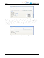
A simplified, yet conservative approach is implemented in order to simulate
derailment loading for LA300 loading.
8.5 How is continuity modelled in splayed girder arrangements?
Series of nodes are typically created on the support axes of piers where link slabs or
cross-beams are defined. These nodes are situated on the projection of each precast girder onto the support axes and are rigidly connected with each other.
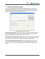
Link slabs (continuity ‘Type 2’ and ‘Type 3’) are modelled by spring elements in the
top slab level connecting the ends of the longitudinal girders with the corresponding
nodes on the support axis. In places where the number and direction of girders
remains the same across the pier this system results in a parallel arrangement of
spring elements as shown in Figure 15a.
In places where the number of girders changes across a support, or where splayed
arrangements are defined, or where the longitudinal direction of the deck changes
the resulting arrangement of spring elements simulating the link slab may look similar
to the one shown in Figure 15b.
At support locations where cross-beams (continuity ‘Type 4’) are defined the same
series of nodes on the support axes are generated. Cross-beam elements connect
these nodes across the width of the deck. The individual nodes are then connected
rigidly with the corresponding end nodes of the longitudinal girders.
(a)
(b)
support axis
Figure 17. Spring elements modelling link slabs.
version 2.0
23