1
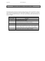
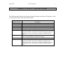
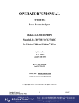
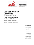
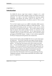
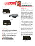
PO Box 3249 Sunriver, OR 97707-0249
541.593.1656 FAX 541.593.5652
[email protected] www.microridge.com
i
TABLE OF CONTENTS
SECTION 1: INTRODUCTION ......................................................................... 1
System Components ........................................................................................... 1
AC Adapter ........................................................................................................ 1
SECTION 2: OPERATION ................................................................................
Front Panel .........................................................................................................
Back Panel .........................................................................................................
Auto Lockout Mode ...........................................................................................
Flow Control Mode ............................................................................................
DIP Switches ......................................................................................................
Internal Pin Jumpers ...........................................................................................
Sample Configurations ........................................................................................
MPX Multiplexers from MicroRidge ..............................................................
UltraCal III Serial Gages from Fowler ............................................................
2
2
2
2
3
4
4
6
6
6
SECTION 3: UTILITY SOFTWARE ................................................................ 7
COM_TEST.EXE .............................................................................................. 7
APPENDIX A: RS232 TO HOST CONNECTOR ............................................. 8
APPENDIX B: PORTS A, B & C CONNECTORS ........................................... 9
Revised 08-20-93, Printed 10-25-00
S/MUX-2 Multiplexer
Section 1
S/MUX Multiplexer
1
INTRODUCTION
The S/MUX Multiplexer is an RS232 serial multiplexer that allows you to connect up to three
serial devices into a single serial port. The S/MUX is intended for use with serial devices that
meet the following criteria:
- All devices are operating with the same communications parameters. For example, the
serial devices connected to ports A, B and C, and the host computer connected to the
RS232 to Host connector are all operating at 9600-N-8-1. Any baud rate up to 9600 is
acceptable.
- Only one of the devices connected to ports A, B or C will be transmitting at any time.
If multiple devices transmit simultaneously, information will be lost or the information
sent to the host computer will be garbled. What actually happens to simultaneously
transmitted information depends on the DIP switch settings.
The S/MUX is very low powered and in most cases can draw its power from the serial port
handshake lines. Pins are provided on the 3 port connectors to provide power to external
devices. Normally you will need to use an AC adapter if power is being drawn from any of
the power supply pins on the port connectors. The power available from each port connector
is:
- Positive (6 to 12 volts) power supply
- Negative (-6 to -12 volts) power supply
- Regulated 5 volt power supply
SYSTEM COMPONENTS
A complete S/MUX Multiplexer package consists of:
- S/MUX Multiplexer unit
- Utility diskette with communications test program on a 5.25" disk
- Operations manual
In addition to the S/MUX package, you will need the appropriate cables to connect your serial
devices to the S/MUX and a cable to connect the S/MUX to your computer.
AC ADAPTER
If you will be drawing power from the S/MUX or your computer cannot provided sufficient
power to the S/MUX, you will also need an appropriate AC adapter. The AC adapter should
provide a DC output between 7 and 15 volts. The current output requirements of the AC
adapter is dependent upon the current required by the devices connected to ports A, B and C.
The AC adapter connector on the S/MUX requires that the center pin be negative.
Section 2
S/MUX Multiplexer
2
OPERATION
The S/MUX Multiplexer can be configured through the DIP switches accessible from the back
of the unit. There are two modes of operation that the S/MUX can be set to. These modes
consist of Auto Lockout and Flow Control.
FRONT PANEL
The front panel of the S/MUX Multiplexer contains three 25-pin male D-sub connectors
labeled as Port A, Port B and Port C. The pin definitions are similar to those found on an
IBM-PC serial port. In addition to the pins required for serial communications, 3 pins provide
power for external equipment. Refer to Appendix B for a description of the pins on the port
connectors.
BACK PANEL
The back panel of the S/MUX Multiplexer contains the output connector (RS232 to Host), an
AC adapter connector and access to the DIP switch banks. The AC adapter is normally only
required if the S/MUX is being used to provide power to external devices connected to ports
A, B or C. The AC adapter can also be wired directly into the cable that plugs into the 25-pin
female D-sub connector. If an AC adapter is used, it should provide a DC output voltage
between 7 and 15 volts. Refer to Appendix A for a description of the pins on the RS232 to
Host connector.
AUTO LOCKOUT MODE
The Auto Lockout mode allows only a single port to send information to the host computer.
For example, if no devices are currently sending information and the device connected to port
B starts sending, ports A and C will be locked out (no inputs will be accepted) until the device
connected to port B has finished its transmission. Once port B has finished, ports A and B
will be enabled to receive information about .1 seconds after there has been no activity on
ports A, B and C.
To set a port to the Auto Lockout mode, set the appropriate DIP switch (4, 5 or 6) to the
"On" position. Refer to the DIP Switch and Sample Configurations paragraphs for additional
details on this mode of operation.
Section 2
S/MUX Multiplexer
3
FLOW CONTROL MODE
The Flow Control mode is intended for use with gage interfaces and multiplexers available
from MicroRidge Systems. The devices available that work with the Flow Control mode are:
GageWay II-S
Interface module for connecting a single digital gage to an RS232
serial port.
GageWay III
Interface module for connecting up to 2 digital gages and some 1200
baud serial devices to an RS232 serial port.
MPX Multiplexer Multiplexer for connecting up to 16 digital and/or serial devices to a
single RS232 serial port.
When the S/MUX multiplexer is configured for this mode, multiple GageWay II-S, GageWay
III and MPX units can be connected to S/MUX and each of these input devices will monitor
the serial line and only transmit on it when it is available.
To set a port to the Flow Control mode, set the appropriate Setup DIP switch positions (4, 5
or 6) to the "Off" position and set the appropriate DTR Control DIP switch positions.
Section 2
S/MUX Multiplexer
4
DIP SWITCHES
There is an 8 position (Setup) and 6 position (DTR Control) DIP switch bank accessible from
the back of the S/MUX multiplexer.
Switch settings for 8 position Setup DIP switchs
Switch
Description
1
Enable or disable the host computer to
send information to the device
connected to port A.
2
Same as switch 1, except for port B
3
Same as switch 1, except for port C
4
Enable port A received data to be locked
out if information is being received by
ports B or C.
Enable port B received data to be locked
out if information is being received by
ports A or C.
Enable port C received data to be locked
out if information is being received by
ports A or B.
Connect the DSR line from the host
computer (pin 6) to the DSR lines (pin
6) from the ports. If all of the port DSR
lines are high and/or disconnected, the
DSR line to the host computer will be
high. If any of the port DSR lines are
pulled low by the port devices, the DSR
line to the host will also be low.
Unused
5
6
7
8
Switch On
Enable transmission
to port A
Switch Off
Disable transmission
to port A
Enable transmission
to port B
Enable transmission
to port C
Port A lockout
enabled
Disable transmission
to port B
Disable transmission
to port C
Port A lockout
disabled
Port B lockout
enabled
Port B lockout
disabled
Port C lockout
enabled
Port B lockout
disabled
Connect port DSR
lines to the host
computer DSR line
Leave the DSR line
to the host computer
unconnected
Section 2
S/MUX Multiplexer
Switch settings for 6 position DTR Control DIP switchs
Switch
Description
1&2
Port A DTR Control :
- The DTR pin for this port will be the
same as the DTR pin from the host
computer. It the host computer DTR
line goes low, this port DTR line will
also go low.
- The DTR pin for this port will always
be high.
- The DTR pin for this port will go low
when the DSR line (pin 6) on one of
the other ports goes low. This is the
switch setting required for the Flow
Control mode of operation and is
used by gage interfaces and
multiplexers from MicroRidge
Systems.
3&4
Port B DTR Control :
- The DTR pin for this port will be the
same as the DTR pin from the host
computer.
- The DTR pin for this port will always
be high.
- The DTR pin for this port will go low
when the DSR line (pin 6) on one of
the other ports goes low.
5&6
Port C DTR Control :
- The DTR pin for this port will be the
same as the DTR pin from the host
computer.
- The DTR pin for this port will always
be high.
- The DTR pin for this port will go low
when the DSR line (pin 6) on one of
the other ports goes low.
5
Switch On
Switch 2 is On
Switch Off
Switch 1 is Off
Switch 1 & 2 are Off
Switch 1 is On
Switch 2 is Off
Switch 4 is On
Switch 3 is Off
Switch 3 & 4 are Off
Switch 3 is On
Switch 4 is Off
Switch 6 is On
Switch 5 is Off
Switch 5 & 6 are Off
Switch 5 is On
Switch 6 is Off
Section 2
S/MUX Multiplexer
6
SAMPLE CONFIGURATIONS
Several S/MUX Multiplexer setups are shown below. These are only intended as samples and
not necessarily the only way to set up the S/MUX for use with these devices.
MPX Multiplexers from MicroRidge Systems
The following configuration would be used if you had 3 MPX-4S multiplexers connected
to an S/MUX. Let's assume that each MPX unit could send information at any time and
that you did not want the MPX connected to port C to receive any computer commands
from the host computer. The DIP switches should be set according to the following
tables:
1
On
2
On
Setup DIP Switch Settings
3
4
5
6
Off
Off
Off
Off
7
Off
8
Off
DTR Control DIP Switch Settings
1
2
3
4
5
6
On
Off
On
Off
On
Off
UltraCal III RS232 Serial Gages from Fowler
The following configuration would be used if you had 3 UltraCal III gages connected to
an S/MUX. Let's assume that the gage connected to port A is a digital indicator and the
gages connected to ports B and C are calipers. The user will be pressing the read button
on the gages connected to ports B and C to initiate the readings. The computer will
toggle the DTR line low and then high to get a reading from the gage connected to port
A. The DIP switches should be set according to the following tables:
1
On
2
On
Setup DIP Switch Settings
3
4
5
6
On
On
On
On
7
Off
8
Off
DTR Control DIP Switch Settings
1
2
3
4
5
6
Off
On
Off
Off
Off
Off
Section 3
S/MUX Multiplexer
7
UTILITY SOFTWARE
The utility software consists of an RS232 communications test program. This program is
distributed on a 360K IBM-PC compatible 5.25" floppy disk. A 720K 3.5" floppy is available
on special request.
COM_TEST.EXE
This communications test program allows you to test the S/MUX Multiplexer and the devices
connected to it. It supports COM1: and COM2: along with the commonly used baud rates
and communications parameters. When the program is started you will be asked to enter the
serial port, baud rate and communications parameters. Certain function keys, as described
below, allow you to control certain aspects of the program.
Function
Key
F1
F2
F3
F4
F5
F9
Label
New
Line
Show ASCII
or
Show Hex
RTR Ready
or
DTR Wait
New
Baud
Clear
Buffr
Exit
Prog
Description
Move the input cursor down 1 line and place it in column 1. Nothing is sent
out the serial port.
Display all of the received information in ASCII or Hex. The hex display is
very useful in determining if you have control characters, multiple linefeeds,
etc. in your data string.
Set the DTR (pin 20) handshake high (Ready) or low (Wait).
Select a new serial port, baud rate and communications parameters. If you
press the Esc key after pressing this function key, the serial port baud rate
and communications parameters will remained unchanged.
Clear the receive data buffer in the PC.
Exit the communications test program.
Appendix A
S/MUX Multiplexer
8
RS232 TO HOST CONNECTOR
The following table describes the function of each of the pins on the 25-pin RS232 to Host Dsub connector located on the back side of the S/MUX multiplexer. In most cases you will be
able to connect the S/MUX directly to a PC with a serial extension cable and will not have to
use an AC adapter.
RS232 to Host
25-Pin Connector
2
3
4
6
7
9
20
Description
Receive data (RxD) from host computer.
Transmit data (TxD) to host computer.
Handshake line (RTS) from host computer. This line, along with pin 20,
is used as a power source if no AC adapter is connected.
Handshake line (DSR) from S/MUX multiplexer.
Signal ground and power supply ground.
7 to 15 volts DC from AC adapter or other DC power source. The ground
from the AC adapter should be connected to pin 7. This AC adapter is
only needed if sufficient power cannot be obtained from pins 4 and 20.
Handshake line (DTR) from host computer. This line, along with pin 4, is
also used as a power source if no AC adapter is connected.
Appendix B
S/MUX Multiplexer
9
PORTS A, B & C CONNECTORS
The following table describes the function of each of the pins on the three 25-pin port (A, B &
C) connectors located on the front of the S/MUX.
Port A, B & C
25-Pin Connectors
2
3
4
6
7
9
10
20
25
Description
Transmit data (TxD) to serial device.
Receive data (RxD) from serial device.
Handshake line (RTS) to serial device.
Handshake line (DSR) from serial device.
Signal ground and power supply ground.
Positive power supply from AC adapter, pin 4 from host computer or pin
20 from host computer. There may not be sufficient capacity to pull power
from this pin if you are not using an AC adapter as the S/MUX power
source.
Negative power supply from voltage inverter connected to the AC adapter
or the receive data (RxD) line from the host computer.
Handshake line (DTR) to serial device.
5 volt DC regulated supply. The total power that can be obtained from
this pin on all 3 ports is 75 ma if an AC adapter is being used as the
S/MUX power source. There may not be sufficient capacity to pull power
from this pin if you are not using an AC adapter as the S/MUX power
source.