1
Nor-Mag
Magnetic AC/DC Powered
General Industrial Meters
USER’S MANUAL
HP-315
November 2010
Notice
HOFFER FLOW CONTROLS, INC. MAKES NO WARRANTY OF ANY KIND WITH
REGARD TO THIS MATERIAL, INCLUDING, BUT NOT LIMITED TO, THE IMPLIED
WARRANTIES OF MERCHANTABILITY AND FITNESS FOR A PARTICULAR PURPOSE.
This manual has been provided as an aid in installing, connecting, calibrating, operating, and
servicing this unit. Every precaution for accuracy has been taken in the preparation of this
manual; however, HOFFER FLOW CONTROLS, INC. neither assumes responsibility for
any omissions or errors that may appear nor assumes liability for any damages that may
result from the use of the products in accordance with information contained in the manual.
HOFFER FLOW CONTROLS' policy is to provide a user manual for each item supplied.
Therefore, all applicable user manuals should be examined before attempting to install or
otherwise connect a number of related subsystems.
During installation, care must be taken to select the correct interconnecting wiring drawing. The
choice of an incorrect connection drawing may result in damage to the system and/or one of
the components.
Please review the complete model number of each item to be connected and locate the
appropriate manual(s) and/or drawing(s). Identify all model numbers exactly before making
any connections. A number of options and accessories may be added to the main instrument,
which are not shown on the basic user wiring. Consult the appropriate option or accessory user
manual before connecting it to the system. In many cases, a system wiring drawing is available
and may be requested from HOFFER FLOW CONTROLS.
This document contains proprietary information, which is protected by copyright. All rights
are reserved. No part of this document may be photocopied, reproduced, or translated to
another language without the prior written consent of HOFFER FLOW CONTROLS, INC.
HOFFER FLOW CONTROLS’ policy is to make running changes, not model changes,
whenever an improvement is possible. This affords our customers the latest in technology
and engineering. The information contained in this document is subject to change.
RETURN REQUESTS / INQUIRIES
Direct all warranty and repair requests/inquiries to the Hoffer Flow Controls Customer Service Department, telephone
number (252) 331-1997 or 1-800-628-4584. BEFORE RETURNING ANY PRODUCT(S) TO HOFFER FLOW
CONTROLS, PURCHASER MUST OBTAIN A RETURNED MATERIAL AUTHORIZATION (RMA) NUMBER FROM
HOFFER FLOW CONTROLS’ CUSTOMER SERVICE DEPARTMENT (IN ORDER TO AVOID PROCESSING
DELAYS). The assigned RMA number should then be marked on the outside of the return package and on any
correspondence.
FOR WARRANTY RETURNS, please have the
following
information
available
BEFORE
contacting HOFFER FLOW CONTROLS:
FOR NON-WARRANTY REPAIRS OR CALIBRATIONS,
consult
HOFFER
FLOW
CONTROLS
for
current
repair/calibration charges. Have the following information
available BEFORE contacting HOFFER FLOW CONTROLS:
1. P.O. number under which the product was
PURCHASED,
2. Model and serial number of the product
under warranty, and
3. Repair instructions and/or specific problems
relative to the product.
1. P.O. number to cover the COST of the repair/calibration,
2. Model and serial number of the product, and
3. Repair instructions and/or specific problems relative to the
product.
HFC 9708
LIMITED WARRANTY
HOFFER FLOW CONTROLS, INC. ("HFC") warrants HFC's products ("goods") described in the specifications incorporated
in this manual to be free from defects in material and workmanship under normal use and service, but only if such goods
have been properly selected for the service intended, properly installed and properly operated and maintained. This warranty
shall extend for a period of one (1) year from the date of delivery to the original purchaser (or eighteen (18) months if the
delivery to the original purchaser occurred outside the continental United States). This warranty is extended only to the
original purchaser ("Purchaser"). Purchaser's sole and exclusive remedy is the repair and/or replacement of nonconforming
goods as provided in the following paragraphs.
In the event Purchaser believes the goods are defective, the goods must be returned to HFC, transportation prepaid by
Purchaser, within twelve (12) months after delivery of goods (or eighteen (18) months for goods delivered outside the
continental United States) for inspection by HFC. If HFC's inspection determines that the workmanship or materials are
defective, the goods will be either repaired or replaced, at HFC's sole determination, free of additional charge, and the goods
will be returned, transportation paid by HFC, using the lowest cost transportation available.
Prior to returning the goods to HFC, Purchaser must obtain a Returned Material Authorization (RMA) Number from HFC's
Customer Service Department within 30 days after discovery of a purported breach of warranty, but no later than the
warranty period; otherwise, such claims shall be deemed waived. See the Return Requests/Inquiries Section of this manual.
If HFC's inspection reveals the goods are free of defects in material and workmanship or such inspection reveals the goods
were improperly used, improperly installed, and/or improperly selected for service intended, HFC will notify the purchaser in
writing and will deliver the goods back to Purchaser upon (i) receipt of Purchaser's written instructions and (ii) the cost of
transportation. If Purchaser does not respond within thirty (30) days after notice from HFC, the goods will be disposed of in
HFC's discretion.
HFC does not warrant these goods to meet the requirements of any safety code of any state, municipality, or other
jurisdiction, and Purchaser assumes all risk and liability whatsoever resulting from the use thereof, whether used singly or in
combination with other machines or apparatus.
This warranty shall not apply to any HFC goods or parts thereof, which have been repaired outside HFC's factory or altered
in any way, or have been subject to misuse, negligence, or accident, or have not been operated in accordance with HFC's
printed instructions or have been operated under conditions more severe than, or otherwise exceeding, those set forth in the
specifications for such goods.
THIS WARRANTY IS EXPRESSLY IN LIEU OF ALL OTHER WARRANTIES, EXPRESSED OR IMPLIED, INCLUDING
ANY IMPLIED WARRANTY OF MERCHANTABILITY OR FITNESS FOR A PARTICULAR PURPOSE. HFC SHALL NOT BE
LIABLE FOR ANY LOSS OR DAMAGE RESULTING, DIRECTLY OR INDIRECTLY, FROM THE USE OR LOSS OF USE OF THE GOODS.
WITHOUT LIMITING THE GENERALITY OF THE FOREGOING, THIS EXCLUSION FROM LIABILITY EMBRACES THE PURCHASER'S
EXPENSES FOR DOWNTIME OR FOR MAKING UP DOWNTIME, DAMAGES FOR WHICH THE PURCHASER MAY BE LIABLE TO
OTHER PERSONS, DAMAGES TO PROPERTY, AND INJURY TO OR DEATH OF ANY PERSONS. HFC NEITHER ASSUMES NOR
AUTHORIZES ANY PERSON TO ASSUME FOR IT ANY OTHER LIABILITY IN CONNECTION WITH THE SALE OR USE OF HFC'S
GOODS, AND THERE ARE NO ORAL AGREEMENTS OR WARRANTIES COLLATERAL TO OR AFFECTING THE AGREEMENT.
PURCHASER'S SOLE AND EXCLUSIVE REMEDY IS THE REPAIR AND/OR REPLACEMENT OF NONCONFORMING GOODS AS
PROVIDED IN THE PRECEDING PARAGRAPHS. HFC SHALL NOT BE LIABLE FOR ANY OTHER DAMAGES WHATSOEVER
INCLUDING INDIRECT, INCIDENTAL, OR CONSEQUENTIAL DAMAGES.
Disclaimer
Specifications are subject to change without notice.
Some pages are left intentionally blank.
HFC 9708
Content
1. APPLICATION.....................................................................................................................................................1
2. MEASUREMENT PRINCIPLE.............................................................................................................................1
3. TECHNICAL DESCRIPTION...............................................................................................................................2
3.1.
GENERAL ..................................................................................................................................................................... 2
3.2.
METER DESIGN ............................................................................................................................................................. 3
3.2.
3.2.1.
Distributed Version ...................................................................................................................................... 3
3.2.2.
Compact Version ......................................................................................................................................... 4
3.2.3.
Protection of commercial meters against unauthorised handling................................................................. 5
MODEL NUMBER DESIGNATION ....................................................................................................................................... 6
4. TECHNICAL PARAMETERS ..............................................................................................................................8
4.1.
4.2.
FLOW SENSOR .............................................................................................................................................................. 8
4.1.1.
Selection of correct sensor size ................................................................................................................... 8
4.1.2.
Operational pressure of measured liquid ..................................................................................................... 9
4.1.3.
Selection of electrode material .................................................................................................................. 10
4.1.4.
Selection of sensor tube lining ................................................................................................................... 10
4.1.5.
Compact or distributed meter version? ...................................................................................................... 10
4.1.6.
Dimensions of flanged sensor ................................................................................................................... 11
4.1.7.
Dimensions of flangeless sensor ............................................................................................................... 12
4.1.8.
Flow sensor specifications ......................................................................................................................... 13
ELECTRONIC UNIT BOX ................................................................................................................................................ 13
4.2.1.
Electronic unit specifications...................................................................................................................... 14
5. METER APPLICATION RULES ..........................................................................................................................15
5.1.
SENSOR PLACEMENT IN PIPING .................................................................................................................................... 15
5.2.
SENSOR EARTHING ..................................................................................................................................................... 17
6. LOW METER INSTALLATION AND OPERATIONAL START ........................................................................18
6.1.
SENSOR INSTALLATION ................................................................................................................................................ 18
6.2.
ELECTRIC CONNECTIONS OF INDUCTION FLOW METER.................................................................................................... 19
6.2.1.
Connection to Power Source ..................................................................................................................... 19
6.2.2.
Output Signal Connections ........................................................................................................................ 20
6.3.
CONNECTION BETWEEN SENSOR AND ELECTRONIC UNIT (DISTRIBUTED METER VERSION)................................................... 20
6.4.
CONNECTION BETWEEN SENSOR AND ELECTRONIC UNIT(DISTRIBUTED METER VERSION, PROTECTION CLASS IP 68)............. 20
6.5.
OPERATIONAL START .................................................................................................................................................. 21
6.5.1.
The ECONOMIC version ........................................................................................................................... 21
6.5.2.
The COMFORT version............................................................................................................................. 21
6.5.3.
Operational data ........................................................................................................................................ 21
6.5.3.1.
6.5.3.2.
Display formats of aggregate values ................................................................................24
Data reset .....................................................................................................................25
7. PROGRAMMING ................................................................................................................................................25
7.1.
HP-315
PROGRAMMING OF THE BASIC MENU ITEMS ................................................................................................................... 26
7.1.1.
Displayed data ........................................................................................................................................... 26
7.1.2.
Samples
7.1.3.
Analog output ............................................................................................................................................ 28
................................................................................................................................................. 28
i
Nor-Mag
7.1.4.
Output functions......................................................................................................................................... 31
7.1.5.
Electrode cleaning ..................................................................................................................................... 38
7.1.6.
Serial line ................................................................................................................................................. 38
7.1.7.
Production data.......................................................................................................................................... 40
7.1.8.
Dose setting............................................................................................................................................... 43
7.1.9.
Zero setting................................................................................................................................................ 43
7.1.10. 100 per cent............................................................................................................................................... 44
7.1.11. Exit ........................................................................................................................................................... 44
7.2. THE PARAMETER SETTING MENU .................................................................................................................................... 46
7.3.
THE PRODUCTION DATA MENU ..................................................................................................................................... 47
8. ERROR CLEARING AND METER REPAIR PROCEDURES...........................................................................48
8.1.
REPLACEMENT PC BOARDS ........................................................................................................................................ 48
8.2.
PROGRAM AND SIMULATION SOFTWARE ........................................................................................................................ 48
8.3.
FLOW-METER REPAIR PROCEDURE ............................................................................................................................... 48
8.3.1.
KV 1.0 Fixture for checking the meter outputs ........................................................................................... 51
8.3.2.
Checking the condition of flow-meter sensor (the compact meter version)................................................ 52
Measurements to be performed on sensor with no fluid inside (the lining is dry) ................... 52
Checking the condition of flow-meter sensor fitted into piping and flooded with
the measured fluid ................................................................................................................... 53
Checking the condition of flow-meter sensor (the distributed meter version with the remote
Electronic unit accommodated with an IP-67 box) ..................................................................................... 54
8.3.3.1.
Measurements to be performed on sensor with no fluid inside (the lining is dry) ................... 54
8.3.2.1.
8.3.2.2.
8.3.3
8.3.3.2.
8.3.3.3.
8.3.4.
8.3.5.
HP-315
Checking the condition of flow-meter sensor fitted into piping and flooded with the
measured fluid ............................................................................................................... 55
Checking the condition of the cable connecting sensor and associated electronic unit .......... 56
Checking the condition of flow-meter sensor (the distributed meter version with the remote electronic
unit accommodated in an IP-68 box) ......................................................................................................... 57
Checking the condition of flow-meter sensor fitted into piping and flooded with the
8.3.4.1.
measured fluid ............................................................................................................... 58
Checking the condition of induction flow meter using the meter diagnostic module of the
Floset 2.0 program..................................................................................................................................... 59
ii
Nor-Mag
1.
APPLICATION
The NORMAG induction flow meter has been designed to measure volume flow rates of electrically conductive
liquids in closed piping systems. Measurements can be done in both flow directions, with high measurement
accuracy over a wide range of flow rates (0.1 to 10 m/s). The minimum required conductivity of the measured
medium is 5 µS/cm.
The signal-processing electronic unit includes a two-line alphanumeric display to show the measured values
where various operational parameters of the meter can be selected by means of an associated keyboard.
Available are two passive binary outputs (indicating frequency, impulse and/or specified limit values), one active
current output and an output to connect a digital communication line. All meter functions and output parameters
can be reset during the meter operation. If the meter is to be used as a commercial (invoicing) meter, some of its
functions are blocked to prevent the user from interfering with the meter readings.
Should the need arise, the user may combine any sensor of the IS X.XX type series with any electronic unit
(C 6.00 or C 7.00) without re-calibration of the meter on a test stand (however, such calibration is required for
commercial meters). The only thing that needs be done is to enter into the electronic unit memory the calibration
constants and excitation frequency of the selected sensor; these data are given on the rating plate of the sensor.
The value of threshold flow rate shall be set between 0.5 and 1% of the specified maximum flow rate.
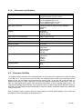
2.
MEASUREMENT PRINCIPLE
The function of an induction flow meter is based on Faraday’s induction law. The meter sensor consists of a nonmagnetic and non-conductive tube with two embedded measuring electrodes to pick up the induced voltage. To
create an alternating magnetic field, two coils are fitted onto the tube in parallel with the plane defined by the
active parts of the measuring electrodes. Now if a conductive liquid flows across magnetic field B, voltage U will
appear on the measuring electrodes proportional to the flow velocity v and the conductor length l.
U=Bxlxv
U
B
l
v
induced voltage
magnetic flux density
distance between the measuring electrodes
liquid flow velocity
As the magnetic flux density and distance between the electrodes are constant, the induced voltage is
proportional to the liquid flow velocity in the tube. The value of the volume flow rate can then be readily
determined as a product of the flow velocity and square section of the tube, Q = v x S.
HP-315
1
Nor-Mag
3.
TECHNICAL DESCRIPTION
3.1.
General
The induction flow meter consists of a sensor through which the measured liquid flows, and an electronic unit
where the low-level signal from the sensor is modified to a standardised form suitable for further processing in
various industrial electronic devices. The output signal is proportional to the volume flow rate of the measured
liquid. The only factor limiting the application of induction flow meters is the requirement that the measured liquid
shall be conductive and non-magnetic. The induction flow meter can be designed either as a compact device or
with the sensor separated from the associated electronic unit. In the former case, the electronic unit is fitted
directly onto the meter sensor, in the latter case it is connected to the sensor by a special cable.
The sensor design shall take into consideration the type of the measured liquid and its operational parameters.
To facilitate fitting into the liquid piping, the sensor can be provided with end flanges, screwing, or it may be of a
sandwich design. The electronic unit is supplied in two basic versions, COMFORT or ECONOMIC. The supply
voltage, types of output signal and communication interface can be selected according to the customer
requirements.
The basic configuration of the induction flow meter includes two insulated passive binary outputs (each with an
optocoupler including a transistor output) and the USB communication interface. This interface is not insulated
as it is used for calibration purposes only. Optional accessories to this basic configuration are insulated current
output and insulated RS 485 communication interface, output relay, INPUT1 and OUTPUT3 for batching (all
these electrically insulated from the electronic unit circuitry).
HP-315
2
Nor-Mag
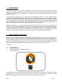
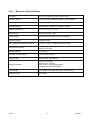
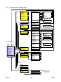
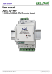
3.2.
3.2.1.
Meter Design
Distributed Version
Flanged sensor connected by a cable with the associated separate electronic unit.
Dimensions of the box to accommodate separate electronic unit and the mounting bracket
HP-315
3
Nor-Mag
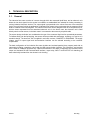
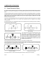
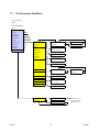
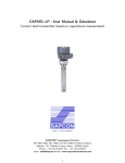
3.2.2.
Compact Version
Compact design solution for a flanged sensor with associated electronic unit
Compact design solution for a flangeless sensor and associated electronic unit
Dimensions of the box to accommodate the flow meter in the compact design version
HP-315
4
Nor-Mag
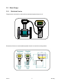
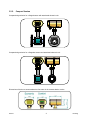
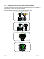
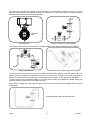
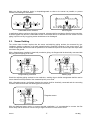
3.2.3.
Protection of commercial meters against unauthorised handling
If the meter is to serve commercial purposes, it shall be provided with official and assembly seals. Installation of
commercial meters is reserved to duly authorised organisation(s).
Placement of official and assembly seals on meters in compact and distributed versions.
Assembly seal
Assembly seal
Official seal
Assembly seal
Official seal
HP-315
5
Nor-Mag
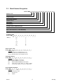
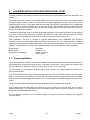
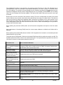
3.2.
Model Number Designation
MODEL NM-( A )-( B )-( C )-( D )-( E )-( F )-( G )-( H )-( I )-( J )-( K )
NOMINAL SIZE
END CONNECTIONS
LINER MATERIAL
ELECTRODE MATERIAL
POWER SUPPLY
GROUNDING
ELECTRONICS
OPTIONAL SERIAL COMMUNICATIONS
OPTIONAL BATCH CONTROL
EMPTY PIPE DETECTION (2" SIZE AND ABOVE)
SPECIAL FEATURES
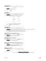
NOMINAL SIZE
MODEL NM-( A )-( )-(
)-(
)-(
)-(
MODEL NM-( )-( B )-( )-( )-( )-( )-( )-( )-( )-(
OPTION ( B )
(F1CS) RF ANSI 150# CARBON STEEL (CS)
(F1SS) RF ANSI 150# STAINLESS STEEL (SS)
(W1CS) WAFER STYLE, FOR ANSI RF 150# CS
)-(
)
SIZE (A):
)-(
)-(
1/2"
3/4"
1"
1 1/4"
1 1/2"
2"
2 1/2"
)-(
)-(
LINER MATERIAL
MODEL NM-( )-( )-( C )-( )-( )-( )-( )-( )-(
OPTION ( C )
(1)
SOFT RUBBER (176°F MAX)
(2)
HARD RUBBER (176°F MAX)
(3)
)-(
)-(
)
HIGH TEMP. RUBBER (194°F MAX)
PTFE TEFLON (300°F MAX), 1/2" THRU 8" SIZES
E-CTFE (266°F MAX), 10" AND 12" SIZES ONLY
ELECTRODE MATERIAL
MODEL NM-( )-( )-( )-( D )-( )-(
OPTION ( D )
(1)
STAINLESS STEEL
(2)
HASTELLOY
(3)
OTHER
HP-315
)
3"
4"
5"
6"
8"
10"
12"
END CONNECTION
(4)
(5)
)-(
)-( )-( )-(
)-(
)-(
)
6
Nor-Mag
POWER SUPPLY
MODEL NM-(
)-(
)-(
)-(
)-( E )-( )-(
)-( )-(
)-(
)-(
)
OPTION ( E )
(1)
24 VDC STANDARD
(2)
115 VAC
(3)
220 VAC
GROUNDING
MODEL NM-( )-( )-( )-( )-( )-( F )-( )-( )-( )-( )-(
OPTIONS ( F )
(1)
STAINLESS STEEL GROUNDED ELECTRODES
(2)
STAINLESS STEEL GROUNDING RINGS:
1/2"
3/4"
1" & 1/4"
1 1/2"
2"
2 1/2"
3"
(3)
(4)
(5)
)
4"
5"
6"
8"
10"
12"
HASTELLOY GROUNDED ELECTRODES
HASTELLOY GROUNDING RINGS
OTHER
ELECTRONICS
MODEL NM-( )-( )-( )-( )-( )-( )-( G )-( )-( )-( )-( )
OPTIONS ( G )
(1)
INTEGRAL RATE AND TOTAL INDICATOR WITH FACE MOUNTED CONTROLS, IP 67
(2)
REMOTE ELECTRONICS FOR IP 67 WITH 19-FT CABLE
(3)
REMOTE ELECTRONICS FOR IP 68 WITH 19-FT CABLE
OPTIONAL SERIAL COMMUNICATIONS
MODEL NM-( )-( )-( )-( )-( )-( )-( )-(H )-(
OPTIONS ( H )
(1)
RS485 SERIAL COMMUNICATION
)-(
OPTIONAL BATCH CONTROL
MODEL NM-( )-( )-( )-( )-( )-( )-( )-( )-( I )-(
OPTIONS ( I )
(1)
BATCH CONTROL FUNCTION
)-(
)-(
EMPTY PIPE DETECTION (2" SIZE AND ABOVE)
MODEL NM-( )-( )-( )-( )-( )-( )-( )-( )-( )-( J )-(
OPTIONS ( J )
(1)
FOR USE WITH SS ELECTRODES
(2)
FOR SE WITH HASTELLOY C ELECTRODES
SPECIAL FEATURES
MODEL NM-( )-( )-(
OPTIONS ( K )
(X)
)-(
)-(
)-(
)-( )-( )-( )-(
)
)
)
)-( K )
ADDITIONAL CABLE LENGTHS
UP TO 150 FT FOR REMOTE IP 67 OPTION AND REMOTE IP 68 OPTION
HP-315
7
Nor-Mag
4.
TECHNICAL PARAMETERS
4.1.
Flow Sensor
The sensor environment must be free of any strong magnetic fields.
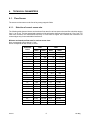
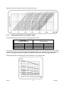
4.1.1.
Selection of correct sensor size
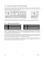
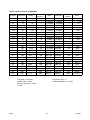
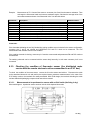
The following table shows minimum and maximum flow rates for various sensor sizes and flow velocities ranging
from 0.1 to 10 m/s. The best operational properties will be achieved at the flow-velocity range of 0.5 to 5 m/s. For
lower flow velocities, the measurement accuracy is worse while at higher flow velocities the turbulences at
contact edges may cause undesirable interference.
Minimum and maximum flow rates for various sensor sizes
Qmin corresponds to flow velocity 0.1 m/s
Qmax corresponds to flow velocity 10.0 m/s
HP-315
LPM
GPM
Diameters
Inches
Qmin
Qmax
Qmin
Qmax
1/2”
3/4”
1”
11/4”
11/2”
2”
21/2”
3”
4”
5”
6”
8”
10”
12”
14”
16”
20”
24”
28”
32”
36”
40”
48”
1.08
2
3
5
7.5
12
20
30
42
72
108
191.6
300
420
583.2
750
1,200
1,667
2,333
3,000
3,633
4,667
6,667
108
200
300
500
750
1,200
2,000
3,000
4,666
7,166
10,433
19,164
30,000
42,000
38,320
75,000
120,000
166,680
233,340
300,000
383,340
466,680
666,660
.29
.53
.79
1.32
1.98
3.17
5.28
7.92
13.3
18.9
29
51
79
111
154
198
317
440
616
793
1,013
1,233
1,761
28.62
52.83
79.25
132.09
198.13
317.01
528.34
792.52
1,232.8
189
2,862
5,063
7,925
11,095
15,410
19,813
31,701
44,028
61,640
79,252
101,266
123,280
176,110
8
Nor-Mag
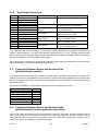
Operational flow rates and flow velocities for various sensor sizes
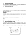
4.1.2.
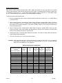
Operational pressure of measured liquid
The standard flow-sensor versions have the following pressure ratings:
Sensor Size
Diameter Inches (DN)
DN 15 – DN 40
DN 50 – DN 200
DN 250 – DN 750
DN 800 – DN 1200
Pressure rating
1/2” - 11/2”
2” - 8”
10” - 29”
32” - 48”
PN 40 (4.0MPa)
PN 16 (1.6MPa)
PN 10 (1.0MPa)
PN 6 (0.6MPa)
580 PSI
232 PSI
145 PSI
87 PSI
On request, any sensor can be supplied for rated operational pressure 87 PSI to 580 PSI. The choice of rated
pressure is primarily derived from the maximum operational pressure of the measured liquid, taking into account
the size of the flanges on the associated piping. Consideration shall also be given to the liquid temperature.
Relationship between operational pressure and temperature of the measured liquid
HP-315
9
Nor-Mag
4.1.3.
Selection of electrode material
In most cases, electrodes made of stainless steel, quality grade 1.4571 (17248) are satisfactory. However, in
special applications it may be necessary to select a higher-quality material. On request, the meter manufacturer
may supply electrodes made of platinum, tantalum, titanium or Hastelloy C4.
4.1.4.
Selection of sensor tube lining
The sensor lining material selection depends on the operational parameters of the measured liquid.
Technical rubber
This lining material is suitable for less corrosive liquids and operational temperatures between 32 and +176°F. It
is sufficient for most applications in water supply and waste water treatment plants. Technical rubber is available
in two grades: HR – hard rubber and SR – soft rubber. Soft rubber lining is recommended for liquids containing
abrasive particles, such as sand grains.
Resistant rubber
Designated SPR, resistant (heavy-duty) rubber is recommended for use with liquids of medium corrosiveness
and operational temperatures between 32 and +194°F. It is suitable for flow measurements of technical water,
condensate and in similar applications. Where the temperatures are likely to exceed +212°F, it is safer to use
Teflon lining.
Teflon
Teflon (PTFE) lining is a universal solution for highly corrosive liquids and temperatures ranging from –4 to
+302°F. Typical applications are in the chemical and food processing industries.
E-CTFE
E-CTFE lining is a universal solution for flow meters from (12”) and higher for corrosive liquids and temperatures
ranging from -4 to +255°F. Typical applications are in the chemical processing industries.
4.1.5.
Compact or distributed meter version?
The distributed meter version is to be used at the measurement spots with ambient temperature exceeding
122°F where the reliable function of the electronic unit would not be ensured at all times. In such cases, use the
distributed meter version and place the separate electronic unit at a location where the ambient temperature
never exceeds 122°F.
To prevent electromagnetic interference via the connecting cable, the sensor and separate electronic unit
of the meter in the distributed version should be located as close as possible to one another. The maximum
cable length depends on the conductivity of the measured liquid (see the following diagram).
HP-315
10
Nor-Mag
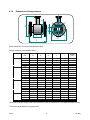
Dimensions of flanged sensor
DN
A
d
4.1.6.
l
D
L
Sensor dimensions for various rated diameters (DN)
Flanges according to standard EN 1092-1.
DN
PN 40
(580 PSI)
PN 16
(232 PSI)
PN 10
(145 PSI)
PN 6
(87 PSI)
1/2″
3/4″
1″
11/4″
11/2″
2″
21/2″
3″
4″
5″
6″
8″
10″
12″
14″
16″
20″
24″
28″
32″
36″
40″
48″
D
4″
4″
4.5″
5.5″
6″
6.5″
7″
8″
9″
10″
11″
13″
17.5″
17.5″
20″
22″
26″
31″
35″
38″
42″
46″
55″
d
2″
2″
3″
3″
4″
4″
5″
5.5″
6″
7.5″
8.5″
11″
14.5″
16.5″
19″
21″
25″
30″
35″
38″
41″
49″
53″
A*
L
l
6″
7″
7″
8″
8″
9″
10″
10″
11″
12″
13″
16″
19″
21″
23″
25″
30″
34″
39″
43″
47″
51″
59″
8″
8″
8″
8″
8″
8″
8″
8″
10″
10″
12″
14″
18″
20″
22″
24″
24″
24″
28″
31″
35″
39″
47″
2.5″
2.5″
27″
27″
27″
27″
27″
27″
27″
5″
5″
8″
8″
12.5″
12.5″
12.5″
12.5″
12.5″
16.5″
16.5″
20″
20″
20″
Weight
[ lbs ]
7
7
7
9
9
13
20
31
35
42
55
91
119
170
203
256
368
694
941
1102
1499
*Dimension A (sensor height) is net of the electronic unit box (or terminal box in the distributed meter version).
The sensor weight data are only approximate.
HP-315
11
Nor-Mag
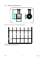
Dimensions of flangeless sensor
D
DN
A
4.1.7.
L
Flangeless sensor dimensions for various rated diameters (DN)
DN
PN 40
(580 PSI)
PN 16
(232 PSI)
.8″
.9″
1″
1.5″
2″
2″
3″
4″
5″
6″
8″
D
2″
3″
3″
4″
4″
5″
5.5″
6″
7.5″
8.5″
11″
A*
L
Weight
[ lbs ]
6″
6″
7″
7″
7.5″
8″
9″
10″
11″
12″
14″
3″
4″
4″
4″
4″
4″
4″
4″
5″
5″
9″
2
4
4
4
7
7
9
9
13
18
22
* Dimension A (sensor height) is net of the electronic unit box (or terminal box).
The sensor weight data are only approximate.
HP-315
12
Nor-Mag
4.1.8.
Flow sensor specifications
Sensor size
Flanged sensors, DN 1/2″ to DN 47″
Flangeless sensors, DN 4/5″ to DN 8″
Operational pressure
PN 40 (4.0MPa) for DN 1/2″ to 1.5″
PN 16 (1.6MPa) for DN 2″ to 8″
PN 10 (1.0MPa) for DN 10″ to 29.5″
PN 6 (0.6MPa) for DN 31″ to 47″
Mechanical connection
Flanges according to ČSN, EN or DIN standards
Flangeless
Others
Earthing
On flanges
Earthing rings
Earthing electrode
Flow velocity of measured liquid
From 0.1 m/s to 10 m/s
Maximum temperature of measured liquid
Up to 302ºF (according used lining)
Minimum conductivity of measured liquid
20 μS/cm, 5 μS/cm in special applications
Empty pipe alarm
From DN 2″
Lining
Soft rubber
Hard rubber
Resistant rubber
Teflon (PTFE)
E-CTFE
Measuring electrodes
Stainless steel, grade 1.4571 (17248)
Hastelloy C4
Platinum
Tantalum
Titanium
Protection class
IP 67
IP 68
Storage temperature
-14ºF to +158ºF at max. relative air humidity 70%
4.2.
Electronic Unit Box
The signal-processing electronic unit is accommodated in a cast aluminium box coated on the surface with paint
of hue RAL 1017. The box is held by four M5 bolts with hexagonal socket heads. Upon loosening the bolts
slightly the box can be rotated around horizontal axis through ±180°. At the rear part of the box there is a
terminal board under a lid held in position by six bolts with hexagonal socket heads. At the bottom of the box
there are cable glands and a special valve preventing condensation of the air humidity inside the box. The
unused gland openings shall be blinded. The front panel of the box is either blinded (the ECONOMIC version) or
fitted with a two-line background-illuminated display unit and a four-button membrane keyboard (the COMFORT
version of the meter).
Prior to putting the meter in service, check the correct sealing of all active glands, blinding of the unused ones
and tightening of the bolts holding the terminal board lid.
HP-315
13
Nor-Mag
4.2.1.
Electronic unit specifications
Line Sizes:
1/2” to 12” (Available up to 48”) (DN 15-1200)
Nominal Pressure:
ANSI 150#, 300#, 600# Max Pressure—Size Dependant
Minimum Conductivity of measured Liquid:
20μS/cm, on agreement with the manufacturer down to 5μS/cm
Electrode Material:
Stainless steel, Hastelloy-C4, platinum, tantalum
Ambient Temperature:
23°F to 131°F (-5°C to 55°C)
Sensor Lining:
Soft or hard rubber, Teflon
Design Version:
Electronics Meter Mounted or Remote Mounted
Piping Connection:
Flanges or Wafer
Max. Temperature of Measured Liquid:
Up to 311°F (155°C), depending on sensor lining
Measurement Accuracy :
±0.2% for 10 to 100%
±0.5% for 5 to 100%
Measuring Range:
0.1 to 10 m/s
Indication of Empty Piping:
From 2” DN 50 Upwards
Displayed Units
Gallons, Liters, Cubic Meters
Outputs (insulated):
Current (0) 4 to 20mA
Frequency 0 to 1,000 Hz
Pulse, 0.001 to 1,000 liters per pulse
Communication line USB, RS 485
Power Supply:
24/115/230V ±10%, 50 to 60 Hz (AC), 24V±10% (DC)
Protection Class
IP67 (IP68)*
HP-315
14
Nor-Mag
5. METER APPLICATION RULES
5.1.
Sensor Placement in Piping
No chemical injection or batching unit (such as chlorine compound injector) should be located at the input side of
the sensor. The insufficient homogeneity of the flowing liquid may affect the flow-rate values indicated by the
meter.
The meter performance will be the best if the liquid flow in the piping is well stabilised; therefore it is necessary
to observe specific rules for the sensor placement in piping. In the contact planes between the sensor and the
adjoining piping sections should be no edges as these would cause flow turbulence. Make sure that straight
piping sections are provided before and after the sensor; their required length is proportional to the inner
diameter of the piping concerned.
If more than one flow-disturbing element such as pipe bend or fitting are located near the sensor, the required
length of straight piping section on the sensor side concerned should be multiplied by the quantity
of such elements.
As required by clause 4.2.1 of standard EN 29104, the inner diameter of the connected pipe should not differ by
more than 3% from that of the sensor.
In the cases of bi-directional flow-rate measurement, the same conditions concerning flow stability shall be met
at the input and output sides of the sensor.
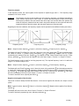
Required straight piping sections
Pipe narrowing
In the cases where the pipe size larger than that of the
meter sensor, it is necessary to use conical reduction
pieces with the angle of taper not exceeding 15° (see the
picture). In the cases of bi-directional flow measurement,
the minimum length of straight piping sections on both
sides is 5 DN. In horizontal sensor installations, to prevent
bubbling, use eccentrically-fitted reduction pieces (see
standard ČSN EN ISO 6817).
Pipe narrowing sections with angles not exceeding 8° can be taken for straight sections.
In the cases where the liquid is pumped, the flow sensor shall always be placed at the output side of the pump to
prevent underpressure in the piping which might damage the sensor. The required length of the straight piping
section between the pump and sensor is then at least 25 DN.
Pump in the piping
Closing valve in the piping
For the same reason, the sensor shall be always placed before the closing valve in the piping.
HP-315
15
Nor-Mag
The sensor can be fitted in the piping in either horizontal or vertical position. However, make sure that the
electrode axis is always horizontal and, if the sensor is mounted in a horizontal position, the flange section for
attachment of the electronic unit box faces upwards.
Elektrode
Electrode
axis
axis
Electrode axis
Sensor mounted in a vertical position
In the cases where the sensor is mounted in a vertical position, the flow direction shall always be upwards.
Risk of liquid aeration
Permanent flooding of sensor
To ensure correct meter function at all times, the measured liquid shall completely fill up the sensor and no air
bubbles shall be permitted to accumulate or develop in the sensor tube. Therefore the sensor shall never be
placed in the upper pocket of the piping or in a vertical piping section where the flow direction is downwards.
In piping systems where complete flooding of the piping cannot always be guaranteed, consider placing the
sensor in a bottom pocket where full flooding is ensured.
If the sensor is located near a free discharge point, such point shall be by at least 2 DN higher than the top part
of the sensor.
Sensor placement near free discharge point
HP-315
16
Nor-Mag
Make sure that the adjoining piping is clamped/supported as close to the sensor as possible, to prevent
vibrations and damage to the sensor.
Undesirable sensor vibrations
Sensor bypass
In applications where continuous liquid flow is essential, a bypass shall be provided to allow for sensor servicing.
A sensor bypass may also be a reasonable solution in the cases where, to dismantle the flow sensor from the
piping, liquid from a very long piping section would have to be discharged.
5.2.
Sensor Earthing
The correct meter function requires that the sensor and adjoining piping sections be connected by lowimpedance earthing conductors to the earth potential and the protection conductor of the power source. The
overall arrangement shall be such that the potentials of the measured liquid at the sensor input and output sides
are close to the ground.
With a flanged sensor installed in electrically conductive piping, the flanges shall be electrically connected with
the piping and the piping put to earth.
Flange earthing connection
Earthing rings
Should the adjoining piping sections be non-conductive, earthing rings or similar arrangement shall be used to
ensure that the electric potential of the measured liquid is put to earth.
With a flangeless sensor, the flanges clamping the sensor shall be electrically connected and the connecting
conductor interconnected with the earthing point on the sensor.
Flangeless sensor
With the distributed meter version, to ensure potential equalisation, it is recommended
to connect the flow
sensor body with the electronic unit box using a copper conductor of cross-section 4mm2.
HP-315
17
Nor-Mag
6.
LOW METER INSTALLATION AND OPERATIONAL START
The meter installation work shall be performed in strict observance of the procedures and rules described in this
manual.
To prevent undesirable interference, the power cables shall be laid at least 25cm away from all signal cables.
The signal cables include the cable connecting the sensor and the associated electronic unit (in the case of a
distributed meter version), output signal cables and the cable of the RS 485 communication line. All cables shall
be laid outside the thermal insulation layer on the piping (if any). Only shielded conductors shall be used to
connect the output signals and the RS 485 line where the shielding shall be connected to the earth potential on
the side of the plant control system.
In applications where high levels of electromagnetic field interference at the measuring location can be expected
(e.g. in the vicinity of power frequency converters), the distributed meter version should be avoided. In these
cases it is also recommended to include a filter in the power supply line to the electronic unit.
Filter specification: The filter is intended to suppress dissemination of the undesirable high frequency
disturbances from the power supply cable to the flow meter system. Use any commercial filter of suitable
parameters including protection class, and install it is close to the meter as possible. If need be, the filter can be
placed in a special protection housing. When installing the filter, observe the applicable safety regulations.
Rated voltage:
Rated current:
Suppression characteristic:
6.1.
250V/50Hz
0.5A and more
10kHz: 10 to 20dB
10MHz: 40dB
Sensor Installation
The measurement point chosen for the sensor installation should ensure that the internal part of the sensor is
fully flooded with the measured liquid at all times. If the sensor is mounted in vertical position, the only permitted
liquid flow direction is upwards. No thermal insulation shall be used on the sensor body.
If the flow meter is to be installed in a pipeline with thermal insulation, the insulation shall be removed at the
sensor insulation point.
The internal diameters of the piping, connecting flanges and the sensor tube shall be identical. The flange faces
shall be perpendicular to the piping. The input and output piping sections including seals shall be perfectly
aligned, with no protruding edges. In the case of a non-conductive piping, use earthing rings on both sides of the
sensor.
The arrow on the sensor body indicates the required fluid flow direction (positive flow direction).
Upon loosening the four bolts holding the electronic unit box in position on the sensor body, the box can be
rotated through ±180°. The same system for the box rotation can be used if the box is mounted on a bracket
attached to a vertical support plate or wall.
Do not expose the electronic unit box to direct sunlight; in the cases of outdoor installation, use a suitable
protection shield.
HP-315
18
Nor-Mag
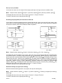
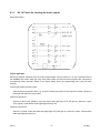
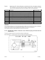
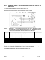
6.2.
Electric Connections of Induction Flow Meter
The terminals for connecting cables can be accessed upon removal of a cover at the rear part of the box
housing the electronic unit. The cover is held in position by six socket-head bolts. A schematic diagram of the
connections is shown on the rear side of the cover.
Examples of labels showing power supply (line voltage or 24VDC source) and meter signal interconnection.
6.2.1.
Terminal
PE
N
U
Connection to Power Source
24V 115V 230V/AC/50 ÷ 60Hz
PE earthing conductor
N neutral conductor
L phase conductor
Terminal
PE
M
C
24VDC
PE earthing conductor
M middle conductor
L+ +24V
To connect the power source, use a standard cable of three conductors of square section not exceeding 3 x
1.5mm2. For ambient temperatures over 122°F, use a cable with rated operating temperature of at least 194°F.
The box grommets will only accommodate cables with outer diameter between 4 and 8mm. Use of any other
cable would disturb the integrity of the IP 67 box.
The earthing conductor shall be longer than both the phase and neutral conductors. This is a safety requirement
as in the case of loosening the cable clamping in the gland, the earthing conductor shall be the last to be
disconnected from the terminal (see clause 6.10.2.2. of standard EN 61010-1).
The power supply line shall be protected by an overcurrent circuit breaker. A seal should be applied on the
breaker to prevent unauthorised handling. The electronic unit has no independent power switch. The
recommended rating of the overcurrent circuit breaker is 4 to 6A.
HP-315
19
Nor-Mag
6.2.2.
Output Signal Connections
Terminal
1
2
3
4
5
6
7
8
9
10
11
12
13
14
15
Polarity
Switching contact
Central contact
Break contact
- pole
+ pole
Conductor B (-)
Conductor A (+)
Anode (+)
Cathode (-)
Optocoupler collector (+)
Optocoupler emitter (-)
Optocoupler collector (+)
Optocoupler emitter (-)
Optocoupl. collector (+)
Optocoupler emitter (-)
Function
Change-over contact
Output relay
(optional)
Current output (optional)
RS 485
(optional)
Dosing (optional)
Binary input 1
Comments
Optocoupler insulated contact
0.3A, 30VDC
Active output, max. loading (Rz) 1,000Ω.
No external power source needed.
To be directly connected
to communication line
Passive input 5VDC, 10mA
Dosing (optional)
Binary output 3
Passive output, requires external power
source and loading resistor
Passive output, requires external power
source and loading resistor
Passive output, requires external power
source and loading resistor
Binary output 2
Binary output 1
The output terminals can be connected to co-operating electronic equipment using standard shielded signal
cables of external diameter 3 to 6.5mm and conductor cross-section 0.5 to 1.5mm2. Shielded conductors shall
also be used to connect all output signals and the communication line where the shielding shall be connected to
the earth potential on the side of the plant control system.
Upon connecting the conductors to the terminals, tighten the bolts holding the electronic box cover and check
the grommet sealing. The unused grommets shall be blinded.
6.3.
Connection Between Sensor and Electronic Unit
(distributed meter version)
In a compact version of the meter, this connection is internal. With a distributed meter version, the electronic unit
shall be connected to the associated sensor be means of a special cable supplied attached on the electronic unit
side. On the sensor side, connect the cable wires paying attention to the wire insulation colours and the terminal
identification labels.
Special cable UNITRONIC Cy PiDy 3x2x0.25 length up to 50m, temperature up to 158°F:
Brown BN
Blue BU
White WH
Green GN
Yellow YE
Yellow and green GNYE
Pink PK
Gray GY
6.4.
A
B
C
D
E
Shielding
W2
W1
Connection Between Sensor and Electronic Unit
(distributed meter version, protection class IP 68)
In the IP 68 version of the flow sensor, the terminal box is sealed by cast plastic and the connecting cable is
fixed on the sensor side. On the electronic unit side, the cable is provided with a screw-on connector with its
mating part mounted on the electronic unit bracket. To prevent unauthorised handling, this connector can be
sealed. The hole for the seal wire is provided in the bracket.
HP-315
20
Nor-Mag
6.5.
Operational Start
6.5.1.
The ECONOMIC version
The induction flow meter of either compact or distributed design must first be fitted mechanically and then the
power supply and output terminals be interconnected. Then switch on the supply voltage. Within a short time,
the meter will be initialized and its operational conditions stabilised. Information on the fluid flow parameters will
start to be communicated from the meter outputs to the co-operating equipment (the plant control system)
equipment.
The ECONOMIC version of the meter does not include any keyboard or display unit. The meter configuration is
always customized. Changes in the configuration and/or setting can be performed via the USB serial
communication line using a computer with the FLOSET 2.0 software.
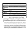
6.5.2.
The COMFORT version
The induction flow meter of either compact or distributed design must first be fitted mechanically and then the
power supply and output terminals be interconnected. Then switch on the power supply voltage. For a short
while, the meter display will show a welcome message. Then the measured flow rate values will appear on the
display.
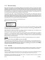
6.5.3.
Operational data
The COMFORT version of the meter includes a two-line alpha-numeric display of 2 x 16 characters with
a background illumination. The display illumination function works in a power-saving mode where the illumination
is automatically switched off 255 seconds following the last push-button action. On depressing any push-button,
the display background illumination is reactivated.
The keyboard includes four push-buttons provided with the following symbols:
1.
2.
3.
4.
Push-button
Push-button
Push-button
Push-button
, the “roller” push-button, direction downwards
, movement upwards, in the direction of the arrow
, password entry push-button
, referred to as the “Enter” push-button
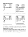
The meter display makes possible reading of different types of data. To switch to the desired data display mode,
use push-buttons (direction downwards) and (direction upwards).
To display temporary data, depress push-button
display mode.
HP-315
. Depress push-button
21
again to return to the total data
Nor-Mag
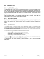
1. Flow rate
Average flow rate determined from the specified number of sample readings. The value is also used for
calculation of other measured quantities.
Flowrate
120.678 gal/m
Display reading: Flow rate
2. Total volume +
The total volume of the fluid passed through the meter sensor in the direction of the arrow on the sensor body
since the measurement start, or the temporary volume, i.e. the volume of fluid passed since the last resetting of
the temporary volume + data.
Total volume +
1234.567 gal
Temp. volume +
765.432 gal
Display reading: Total volume +
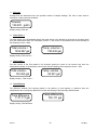
3. Total volume –
The total volume of the fluid passed in the direction against the arrow on the sensor body since the
measurement started, or the temporary volume since the last resetting of the temporary volume – data.
Total volume 123.456 gal
Temp. volume 65.321 gal
Display reading – Total volume –
4. Total difference
The difference between fluid volumes passed in the positive (+) and negative (-) directions since the
measurement start, or temporary difference from the last resetting of the temporary difference data.
Total difference
1111.111 gal
Temp.difference
700.111 gal
Display reading: Total difference
HP-315
22
Nor-Mag
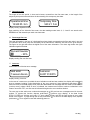
5. Operational time
The length of the time period, in hours and minutes, counted from the first meter start, or the length of the
temporary time period measured since the last resetting of the temporary time data.
Operational time
12345:55 h:m
Temporary time
543:21 h:m
Display reading: Operational time
Upon switching off the induction flow meter, the data readings under items 2, 3, 4 and 5 are stored at the
EEPROM unit and restored upon each new meter start.
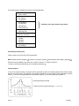
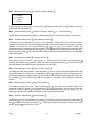
6. Percentage flow rate
Flow rate information in the form of a horizontal bar whose length corresponds to the flow rate value in per cent
of a selected 100% value (need not necessarily be the same as the maximum flow rate for the given sensor).
The figure on the right side offers the digital form of the same information. The minus sign before the figure
indicates negative flow data.
Percent flowrate
▌▌_____ - 20%
Display reading: Per cent flow rate
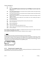
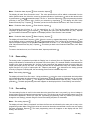
7. Last error
Abbreviated text of the last error message.
Last error
7:sensor discon.
Last error
E-007 015/015
Display reading: Last error
In the case of a meter error, provided the error-indication mode has been enabled, the display will immediately
show a message including a short description of the error concerned. Upon depressing push-button , the
meter will return to the data display mode, while the abbreviated error message and error code are stored in the
“previous errors” register. While an error is indicated, the measurement functions continue undisturbed. In the
cases of errors E6 or E7, zero flow rate is indicated throughout the error condition duration.
The user may review earlier error codes and messages up to 255 previous error messages stored in the error
(previous error display). In the data format
register. To access this function, depress push-button
E-XXX YYY/ZZZ are: XXX the error code, YYY error ordinal number, and ZZZ the total number of error codes
stored in the register. To page through the list use push-button . To return to the data display mode, depress
push-button . Error register is reset with switching power on.
HP-315
23
Nor-Mag
The error messages are:
E0:
No error.
E1:
Error in CRC EEPROM. Incorrect data check sum in the EEPROM unit. This error may occur
when the processor, following a power failure, does not manage to store all data in the
EEPROM unit.
E2:
OUT1 (multi-functional output) is in the impulse mode of operation and the memory block storing
the unsent impulses overflows.
E3:
OUT2 (multi-functional output) is in the impulse mode of operation and the memory block storing
the unsent impulses overflows.
E4:
Multifunctional output RELAY is set for impulse output and the memory block storing the unsent
impulses overflows.
E5:
WDOG: the processor reset condition due to the overflow in the timer controlling the length of
the programming loop.
E6:
Not fully flooded piping.
E7:
Open current loop in the impulse generation circuitry of the meter sensor.
E8:
Error in +5V power line.
E9:
Error in +24V power line.
E10:
Error in -5V power line.
E11:
Actual flow rate exceeded the selected Imax value.
E12:
Failure in frame receipt confirmation while communicating via a serial line.
E13:
Error no processed
Error indication mode enabled: error information is displayed and entered into the error register. Some errors
result in setting the indicated flow rate at zero.
Error indication mode disabled: the error information is entered into the error register.
8. Dosing
Dosing is visible and functional provided this data display mode has been selected.
The selected fluid volume (dose) will wait for the active initiation signal to be brought to terminals 8-9. As soon
as such signal is received, a count towards zero will commence. Upon reaching zero, OUT3 will close. The
dosing action can be repeated by depressing push-button . To interrupt dosing, use push-button . To set the
required dose, follow the respective procedure in the programming menu.
Dosing mode
500.00
l
Display reading: Dosing mode
6.5.3.1.
Display formats of aggregate values
If the displayed value occupies more than 11 digit places including the decimal point, the calculated value will be
displayed alternately with the selected measurement unit.
HP-315
24
Nor-Mag
6.5.3.2.
Data reset
The user is not permitted to reset the aggregate data values under items 2, 3, 4 and 5. Resetting is only possible
(another
with running (“temporary”) values associated with items 2, 3, 4 and 5 accessible via push-button
will return the display to the total value display mode). When a temporary value is
depression of push-button
to discontinue the temporary value mode, and depress push-button
to
displayed, depress push-button
and after that push-button , return to the
reset the temporary value. By depressing any of push-buttons
total value display mode. If you stop the temporary mode and wish not to reset the temporary value, depress any
, whereby the count continues. To return to the total value mode, depress push-button .
of push-buttons
This procedure will reset the edited temporary value only, the other temporary values will be unaffected.
7.
PROGRAMMING
The induction flow meter can be programmed in two ways: using a computer connected to the serial meter
interface, or using its own keyboard. The following description concerns the keyboard (push-button)
programming procedures.
The keyboard includes four push-buttons provided with the following symbols:
1. Push-button , the “roller” push-button, direction downwards;
2. Push-button , movement to the right in the direction of the arrow, direction upwards;
, password entry push-button, movement upwards in the direction of the arrow,
3. Push-button
movement back in the menu;
4. Push-button , referred to as the “Enter” push-button (command confirmation).
In any menu, the selected item is on the first line with the first character blinking.
Entry to the programming mode, movement within a menu and data saving
and then . The programming mode is protected
To enter the programming mode, depress push-button
against unauthorised action by a password (a four-digit number) that needs be entered before accessing the
basic programming menu. Upon delivery from the manufacturing plant, every new meter has a password of
0000.
Password
0000
Display reading: Password
With a new meter, enter password 0000 and confirm by push-button . Provided you have already chosen your
own password, enter the same and confirm by depressing push-button . Prior to leaving the programming
mode, the password can be changed without any limitation.
to move the cursor to the right. Upon reaching the extreme right position, the cursor will
Use the push-button
return to the left side of the line. The cursor is a short horizontal line to be placed under the character we wish to
edit/change.
to change the selected character in the direction upwards, or push-button
in the
Use the push-button
direction downwards. Upon reaching the last character in the character series available, the first eligible
character will reappear.
Upon completing the editing action, confirm your choice of password by push-button . Should you enter an
incorrect password, the display will read “Incorrect password Try again” while the program will return to the data
display mode.
HP-315
25
Nor-Mag
Password OK
Press any key
Display reading: Confirmation of correct password entry: Password OK. Press any key.
With the display reading “Password OK Press any key”, depress any push-button (preferably
basic programming menu.
) to enter the
The two-line display will always show two of the following basic menu options:
Displayed data
Samples
Analog output
Output functions
Electrode clean
Serial line
Production data
Dose setting
Zero setting
100 percent
Exit
Display reading: The basic menu options
and
to move upwards and downwards in the menu. As in any meter menu, the selected
Use push-buttons
item is on the first display line with the initial character blinking.
to enter a subordinated menu, or to edit a menu item. When in a subordinated menu,
Depress push-button
to return to the higher-level menu (the “Escape” function). When in the basic menu, the
depress push-button
Escape command will bring forth the possibility to terminate the programming mode via the selection of the “Exit”
item of the basic menu.
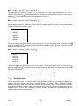
7.1.
7.1.1.
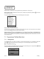
Programming of The Basic Menu Items
Displayed data
The “Displayed data” menu allows the operator to choose which parameters are to be displayed. Using pushbuttons and , select parameters from the following list. The Flow Rate display cannot be cancelled.
Menu: Displayed data, depress
The two-line display unit will always show two of the items from the following menu. Use push-buttons
to page upwards and downwards through the menu items.
and
Flow rate
Total volume +
Total volume Total difference
Operational time
Percent flow rate
Last error
Dosing mode
HP-315
26
Nor-Mag
Menu: Displayed data, depress
/ Total volume depress
and
to go up and down in the
Display line 1 will read “Do not display”, line 2 “l/s …. l“. Use push-buttons
to return to the “Displayed data” menu. If you wish to
menu items. If you choose “Do not display”, depress
display If you wish to display “Total Volume +”, select the “Total Volume +” item on the menu, depress pushbutton , skip line 1 (Do not display) and select line 2, “l/s …. l“ (flow-rate unit … volume unit). Using push(downwards) and
(upwards), select the desired flow-rate and volume units and confirm the
buttons
selection by depressing . The display line 1 will then show “0” and line 2 “0.0“. Using push-buttons
(upwards), select the desired number of decimal positions, confirm the selection by
(downwards) and
depressing and return to the “Displayed Data” menu.
Comment:
The measurement unit selected for “Flow Rate” is automatically set for all other flow-rate quantities referred to in
the Programming menu.
The measurement unit selected for “Total Volume +” is automatically set for all other flow-volume quantities in
the Programming menu.
The measurement units for the “Total Volume –“ and “Total Difference” quantities can be selected as need be,
and their selection will not affect any other measured quantities to be set within the Programming menu.
Table of flow-rate and volume units
l/s
….
l
l/min ….
l
l/h
….
l
m3/s ….
m3
m3/min….
m3
m3/h ….
m3
GPS ….
G
GPM ….
G
GPH ….
G
Table of decimal positions
0
0.0
0.00
0.000
0.0000
0.00000
0.000000
User-specified units:
When defining a user-specific unit, it is necessary to enter a conversion constant (a multiple of the standard flowrate or volume units – “l/s” or “l”, then depress , define the unit name (six characters), depress , define
number of decimal positions, depress and return to the “Displayed Data” menu.
Example: the desired flow rate unit is US barrel per second; the conversion constant is 0.006283811; unit name
bl/s; number of decimal positions 0.000.
The same procedures apply to parameter setting with Flow Rate, Total Volume +, Total Volume – and Total
Difference.
While setting the parameters of Operational Time, Per Cent Flow Rate, Last Error and Dosing, the options to
select from are only “Display” and “Do Not Display”.
To leave the “Displayed Data” mode and return to the basic programming menu, depress push-button
HP-315
27
.
Nor-Mag
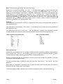
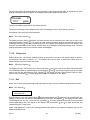
7.1.2.
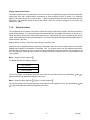
Samples
The number of samples N, on the basis of which the average flow rate value is determined, can be set within the
range of 1 to 255. While the measurement frequency is 6.25Hz (or 3.125, 1 or 0.5Hz), fast (step) changes in the
flow rate will be smoothened within the interval of 0.08 to 20.40s (0.16 to 40.80s, 0.5 to 127.5s or 1 to 255s). The
averaging feature is useful in the cases where the flow through the meter sensor is unstable, the fluid is turbulent
or where there are air bubbles trapped in the fluid flow.
The averaging function helps suppress fast changes in the fluid flow rate. Average flow rate as measured and
displayed is the parameter used to calculate other meter outputs.
Current flow rate
Average flow rate
Sampling
Suppression of step changes in flow rate
Menu: Number of samples, depress
The display will read “Number of samples xxx“. Replace xxx by a number from the range of 1 to 255 (usually 25
and increase/decrease this number using
or
,
is chosen). Move the cursor using push-button
respectively. Confirm the selection by push-button . The display will then read “Value entered Press any key”.
Press or any other push-button. This action will take you back to the basic menu.
7.1.3.
Analog output
Setting options:
Connected to terminals 4 and 5 is a programmable current output. It is an active current output, insulated from
other meter parts. The maximum output load is 1,000Ω. Depending on the fluid-flow characteristics, the output
can be used in four different modes of operation (see the graphs below) and in two selectable measurement
ranges.
The two-line display unit will always show two of the items from the following menu. Use push-buttons
to page downwards and upwards through the menu items.
and
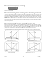
Menu: Analog output, depress
0…+Q Output
0...-Q Output
|Q| Output
–Q...+Q Output
Fixed current 0…20
In all operational modes excepting the “Fixed Current” mode, the current output range can be user defined.
HP-315
28
Nor-Mag
Menu: Analog output, depress
/ Output 0...+Q, depress
Output 0…20mA
Output 4…20mA
Selection of current output
Menu: Analog output, depress
/ Output 0...+Q, depress
/ Output 0…20mA, depress
/ Flow rate for Imax
The current output setting consists of defining flow rate Qmax corresponding to Imax. Move the cursor using
and . Select the desired Qmax
push-button , and increase/decrease the Qmax value using push-buttons
and confirm the setting by depressing . The display will then read “Value Entered Press Any Key”. Press any
push-button. This action will take you back to the main programming menu, item “Analog
key, preferable the
output”.
In the “Fixed current” mode, the output current can be set within the range of 0 to 20mA. This mode is used for
meter servicing purposes.
Menu: Analog output, depress
/ Fixed current 0…20, depress
/ Fixed current 0…20mA
and .
Move the cursor using push-button , and increase/decrease the current value using push-buttons
Select the desired current value and confirm the setting by depressing . The display will then read “Value
Entered Press Any Key”. Press any key, preferably . This action will take you back to the main menu, item
“Analog Output”. At the same time, the defined current will start to flow through the output circuit.
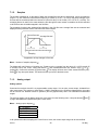
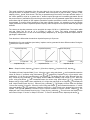
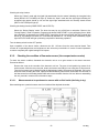
The following graphs show the relationships between current I and flow rate Q for various operational modes:
Output current for 0 ...+Q
Output current for 0 ...-Q
Output current for |Q|
HP-315
Output current for –Q ...+Q
29
Nor-Mag
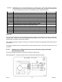
Examples of analog output interconnections
Q+
Equipment with a current input
Q-
2 pieces of equipment with current inputs.
Outputs 1 and 2 serving the purpose of
identifying fluid flow direction.
Multifunctional outputs programmed to identify the fluid flow direction and to negate the flow direction, will divide
the analog output operated in the “Absolute Flow-Rate Value” mode into two outputs, one for each flow direction.
Equipment with voltage input
Current output connected as a voltage
source to feed the (passive) output 2
The output voltage for the co-operating equipment is defined as the voltage drop on resistor R. It holds:
U = I R.
For the voltage range of 0…10V, select R = 500Ω and the analog current output range 0…20mA. Resistor R
shall be placed as close to the input terminals of the co-operating (controlled) equipment as possible. The
maximum voltage (voltage drop on the resistor) is 10V. The input impedance of the controlled equipment shall
be at least 100 times higher than that of resistor R.
The interconnection of the current output as an auxiliary power source for the binary outputs is shown in the
above picture. This arrangement assumes that the current output is not used for the purposes of flow rate
indicator. Here the current output needs be set in the “Fixed Current” mode of operation. The voltage drop on
resistor Ri is used as supply voltage for the binary output (via resistor Rz). The input impedance of the
associated equipment shall be at least 10 times higher than that of resistor Rz, while Rz shall be at least
10 times higher than Ri. It holds: Ri < Rz < input impedance of the co-operating equipment.
HP-315
30
Nor-Mag
Analog output specifications
The analog output signal is controlled by a 12-bit DA converter. The operational range 0 to 20mA is divided into
4,096 steps. One step (1LSB) therefore corresponds to about 0.005mA (0.025% of 20mA). This resolution
applies to all output ranges. The current range 4 ... 20mA is software-defined with the converter steps reduced
accordingly. The maximum voltage at the current output is 20V; the maximum resistance of the current loop
therefore is 1,000Ω.
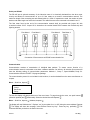
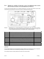
7.1.4.
Output functions
The configuration of the induction flow meter includes two binary multifunctional outputs, electrically isolated by
means of optocouplers. The output transistors of the optocouplers are accessible via terminals 12-13 and 14-15.
These are passive outputs that need external power source. Alternatively they can be powered by the analog
output in the fixed-current mode as described above. The binary outputs can be loaded and repeatedly switch on
and off currents 1 to 50mA.
Default settings: Output 1: frequency output, Output 2: impulse output.
Flow meter can be equipped with an output relay, designated in the menu as item "Relay Functions". Electrically
isolated relay contacts are accessible via terminals 1-2-3. For impulse output, both the impulse width and the
minimum gap length are set at 0.5s. To ensure correct functioning of the impulse function, it is necessary to set
the output impulse constant (the fluid volume per impulse) so that the memory block of unsent impulses would
never overflow.
Menu: Output functions, depress
The display will offer the following selection:
OUT1 function
OUT2 function
RELAY function
The two-line display unit will always show two of the items from the above menu. Use push-buttons
page downwards and upwards through the menu items.
Menu: Output functions, depress
and
/ Output 1 function, depress
The two-line display unit will always show two of the items from the respective menu. Use push-buttons
to page downwards and upwards through the menu items.
HP-315
to
31
and
Nor-Mag
The output functions available are shown in the following table:
Permanently open
Perm. closed
|Q| impulses
Q+ impulses
Q- impulses
Q+ frequency
Q- frequency
|Q| frequency
Fixed frequency
Negative flow
Non-neg. flow
Error occurred
No error occurred
Q>Qlim.
Q<Qlim.
|Q|>Qlim.
|Q|<Qlim.
Cleaning
Not cleaning
Frequency can not be used for relay output
Permanently closed (open)
These modes are only used for servicing purposes.
Menu: Output functions, depress
/ Output 1 (2) function, depress
/Permanently closed (open), depress
This will return the display to the menu item “Output 1 Function” or “Output 2 Function”.
To return to the basic programming menu, depress push-button .
Impulse outputs
In any of the impulse modes, an impulse will be generated as soon as a defined (preset) fluid volume passes
through the meter sensor. The impulse mode requires specification of the following three parameters: impulse
width “tU“, minimum time gap between two successive impulses “tD“ and fluid volume per impulse “V”.
Impulse generation principle
It holds: maximum impulse frequency = 1 / (tU + tD)
HP-315
32
Nor-Mag
This mode provides for integration of the flow rate values in time. As soon as a preset fluid volume V passes
through the meter, an impulse of width tU is generated. After each impulse, a gap of at least tD follows. If, after
elapsing of the tD period, fluid volume V has not yet passed through the sensor, the output remains inactive. If
the volume passed is equal to or greater than V, another impulse plus gap are immediately generated. Should
the preset volume V pass before the end of the previous impulse, the non-generated impulse will be stored in an
accumulator with the capacity of 255 impulses. Should the impulse accumulator overflow, an error message will
be generated. To ensure correct functioning of the meter impulse function, it is necessary to set the impulse
output parameters so that the expected impulse frequency shall correspond to the impulse width and gap length
selected.
The volume per impulse parameter can be set within the range of 0.001 to 1,000,000 litres. The impulse width
and gap length can be set at 10 to 2,550ms in steps of 10ms. The setting procedure consists
of selecting numbers from 1 to 255 on the meter display. Multiplied by 10, the figure shows the impulse width or
gap length in milliseconds.
From the above it follows that the maximum impulse frequency is 50 per sec.
Regarding the flow rate conditions (see below), impulses can be generated in three different modes. During the
tU periods, the output is closed.
Impulse frequency
Flow rate
Impulses for |Q|
Menu: Output functions, depress
Impulse frequency
Flow rate
Impulses for Q+
/ Output 1 (2) function, depress
Impulse frequency
Flow rate
Impulses for Q/ Impulses for |Q|, depress
The display will read “Impulse Width [1] xxx“. Move the cursor using push-button , and increase/decrease the
or , respectively. Replace xxx by a figure which, when
values at various “x” positions using push-buttons
multiplied by 10, will give the impulse width in ms. Depress . The display will read “Value Entered Press Any
Key”. Press any key, preferably . The display will then show the message “Gap Length [1] xxx“. Move the
or , respectively.
cursor using push-button , and increase/decrease the values using push-buttons
Replace xxx by a figure which, when multiplied by 10, will give the gap length in ms. Depress . The display will
read “Value Entered Press Any Key”. Press any key, preferably . The display will then show the message
“Volume Per Impulse [1] xxxxxxx“. Move the cursor using push-button , and increase/decrease the “x” values
or , respectively. Replace xxxxxxx by a figure equal to the desired fluid volume per
using push-buttons
impulse. This figure is elsewhere referred to as the impulse constant or impulse number. Depress . The
display will read “Value Entered Press Any Key”. Press any key, preferably . This will return the display to the
menu items “Output 1 Function” or Output 2 Function”. To return to the basic menu, depress push-button .
HP-315
33
Nor-Mag
Impulse number selection for NORMAG
l/m
Imp.
number
l/imp
gallon/m
0.777
1.8
3.33
5
8.33
12.5
20
33.33
50
77.77
119.44
180.55
319.4
500
700
972
1250
2000
2778
3889
5000
6389
7778
11111
1
1
1
1
5
5
5
10
10
50
50
50
100
100
500
500
500
500
1000
1000
1000
5000
5000
5000
0.205261
0.475509
0.879693
1.320860
2.200553
3.302150
5.283441
8.804854
13.20860
20.54466
31.55271
47.69626
84.37655
132.0860
184.9204
256.7752
330.2150
528.3441
733.8699
1027.365
1320.860
1687.795
2054.730
2935.216
Diameter
Dimension
Qmax
Inches
DN
1/2”
3/4”
1”
11/4”
11/2”
2”
21/2”
3”
4”
5”
6”
8”
10”
12”
14”
16”
20”
24”
28”
32”
36”
40”
48”
10
15
20
25
32
40
50
65
80
100
125
150
200
250
300
350
400
500
600
700
800
900
1000
1200
Qmax
1 US gallon = 3.785412 l
Impulse width = 100ms
Minimum gap length = 100ms
f <= 5Hz
HP-315
Coefficient
3.785412
3.785412
3.785412
3.785412
3.785412
3.785412
18.92706
18.92706
18.92706
18.92706
37.85412
37.85412
189.2706
189.2706
189.2706
378.5412
378.5412
1892.706
1892.706
1892.706
1892.706
1892.706
1892.706
3785.412
Imp.
number
gallon/imp
1
1
1
1
1
1
5
5
5
5
10
10
50
50
50
100
100
500
500
500
500
500
500
1000
Qmax
gallon/m
12.32
28
53
79
132
198
317
528
793
1233
1893
2862
5063
7925
11095
15406
19813
31700
44032
61631
79251
101268
123284
176113
0.264172037 gall = 1 l
15.85032224 gall/min = 60 l/min
34
Nor-Mag
Uniform output impulses
With series-5 meters (including boards FNA5, FNP5, FNS5 and FNZ5), the user may select the so-called
uniform output impulses. These can only be set at the OUT2 output. The standard OUT2 setting on board FNA5
is facilitated by jumper W1 1-2. To set uniform output impulses, remove jumper W1 1-2 and install jumper
W1 2-3. Further setting is done by means of the meter keyboard and display.
To set the uniform output impulse mode:
1. Enter the programming menu, select “Production Data” and check the sensor size – e.g. DN40. Return
to the basic menu.
2. Select “Output Functions”, depress Enter. Select “Output 2 Function”, depress Enter. Select “Frequency
for Q+” (or Frequency for Q-“ or “Frequency for |Q|”), depress Enter. Set the value of flow rate per 1 kHz
with respect to the sensor dimension. In our case, for DN40, Qmax is 12.5 l/s (see the table below).
Return to the basic menu.
3. Select “Production Data”, depress Enter. Select “Base Frequency”, depress Enter. Enter the value
shown in the table. In the case of DN40, the base-frequency value is 8,192. Return to the basic menu
and leave the programming menu by selecting “Exit”.
4. Install jumper W2 3-4 on analog board FNA5 (see the table). The position of jumper W2 determines the
output voltage-divider parameters.
5. This is all you need to do to set uniform output impulses.
Comment: If the actual flow-rate unit is other than litres per second (l/s), the value of 12.5 l/s needs be
recalculated. For example, if the actual unit is m3/h, multiply 12.5 by 3.6 = 45 m3/h; enter this
value as the “Flow Rate Per 1 kHz” parameter.
Uniform output impulse setting table
HP-315
Calorimeter impulse
constant
[ litres per impulse ]
Flow
sensor
DN
Qmax
[ l/s ]
Output
frequency
[ Hz ]
Base
frequency
[ Hz ]
Jumper
position on
board FNA5
100
100
100
100
100
100
100
100
100
15
20
25
32
40
50
65
80
100
1,8
3,33
5
8,33
12,5
20
33,33
50
77,77
0,018
0,0333
0,05
0,0833
0,125
0,2
0,3333
0,5
0,7777
4718,592
8729,395
3276,8
5459,1488
8192
1638,4
2730,394
4096
6370,918
W2 5-6
W2 5-6
W2 3-4
W2 3-4
W2 3-4
W2 1-2
W2 1-2
W2 1-2
W2 1-2
1000
1000
1000
1000
1000
1000
125
150
200
250
300
350
119,44
180,55
319,4
500
700
972
0,11944
0,18055
0,3194
0,5
0,7
0,972
7827,6198
1479,066
2616,525
4096
5734,4
7962,624
W2 3-4
W2 1-2
W2 1-2
W2 1-2
W2 1-2
W2 1-2
35
Nor-Mag
Frequency outputs
In the frequency modes, the output signals will be impulses of impulse-to-gap ratio 1:1. The frequency range
available is from 1Hz to 10kHz.
Comment:
The electronic unit of the meter includes only one frequency generator. It is therefore impossible to
select different frequencies for each output, or combine the fixed-frequency mode at one output
with frequency related to flow rate mode at the other output. On the other hand, the operator may
select the frequency related to flow rate mode in the positive direction at one output with that in the
negative direction at the other output, with the same frequency-to-flow-rate ratios.
Regarding the flow rate conditions, the frequency outputs can be operated in three different modes (see below).
Frequency for Q+
Menu: Output functions, depress
Frequency for Q-
/ Output 1 (2) function, depress
Frequency for |Q|
/ Frequency for Q+, depress
The display will read “Flow Rate Per 1kHz xxxx”. Move the cursor using push-button , and increase/decrease
or
, respectively. Replace xxxx by a figure
the values at various “x” positions using push-buttons
representing the maximum flow rate. Depress . The display will read “Value Entered Press Any Key”. Press
any key, preferably . This will return the display to the menu items “Output 1 Function” or “Output 2 Function”.
The fixed-frequency mode is used for servicing purposes only. The required frequency is set in Hz within the
range of 1 to 10,000 in steps of 1Hz.
Menu: Output functions, depress
/ Output 1 (2) function, depress
/ Fixed frequency, depress
The display will read “Fixed Frequency xxxxx“. Move the cursor using push-button , and increase/decrease the
or , respectively. Replace xxxxx by a figure equal to the desired frequency in
“x” values using push-buttons
Hz. Depress . The display will read “Value Entered Press Any Key”. Press any key, preferably . This action
will return the display to the menu items “Output 1 Function” or “Output 2 Function”.
To return to the basic menu, depress push-button .
Negative (non-negative) flow direction
This mode is used to identify the fluid flow direction. In the case of negative flow direction, the output is closed
(open).
Menu: Output functions, depress
depress .
/ Output 1 (2) function, depress
/ Negative (Non-negative) flow direction,
The display will return to the menu items “Output 1 Function” or “Output 2 Function”.
To return to the basic programming menu, depress push-button .
HP-315
36
Nor-Mag
Error (no error) condition
In the case of a meter error, the output will close (open) and stay so as long as the error condition exists.
Menu: Output functions, depress
/ Output 1 (2) function, depress
/ Error (No error) condition, press
The display will return to the menu items “Output 1 Function” or “Output 2 Function”.
To return to the basic menu, depress push-button .
Exceeding (dropping below) the limit values of flow rate
In the cases of exceeding (dropping below) the preset flow-rate limit values, the output will close (open). Upon
return within the normal operating range, the output will open (close) again with a preset hysteresis. Regarding
the flow rate conditions, there are four different modes of operation:
Q > Q lim.
Q < Q lim.
IQI > Q lim.
IQI < Q lim.
Menu: Output functions, depress
/ Output 1 (2) function, depress
/ Q > Q lim., depress
The display will read “Flow Rate Limit [1] xxxxxx“. Move the cursor using push-button , and increase/decrease
or , respectively. Replace xxxxxx by a figure equal to
the values at various “x” positions using push-buttons
. The display will read “Value
the flow rate which, when exceeded, should cause the output to close. Depress
Entered Press Any Key”. Press any key, preferably . The display will then show the message “Hysteresis [1]
or ,
xxxx”. Move the cursor using push-button , and increase/decrease the “x” values using push-buttons
respectively. Replace xxxx by a figure representing hysteresis, between the closing and opening output
functions. Depress . The display will read “Value Entered Press Any Key”. Press any key, preferably . The
display will return to the menu items “Output 1 Function” or “Output 2 Function”.
To return to the basic menu, depress push-button .
Electrode cleaning in progress (No cleaning)
While the electrode cleaning process is in progress, the output is closed (open).
Menu: Output functions, depress
depress
/ Output 1 (2) function, depress
/ Cleaning in progress (No cleaning),
The display will return to the menu items “Output 1 Function” or “Output 2 Function”.
To return to the basic menu, depress push-button .
HP-315
37
Nor-Mag
7.1.5.
Electrode cleaning
During the meter operation, non-conducting substances may accumulate in the form of a layer on the sensor
electrodes. This increases the contact resistance between the electrode and the measured fluid and results in
decreased measurement accuracy. The FN 20XX flow meter offers a sensor electrode cleaning function without
sensor dismantling. The cleaning method is based on the electro-chemical phenomenon where the electrodes
are connected to an AC voltage source causing the accumulated layer to dissolve in the measured fluid. It is
recommended that the cleaning process be repeated in regular intervals.
The cleaning cycle lasts 1 minute. Measurements are discontinued during the cleaning action while the
immediately preceding flow conditions are being simulated. The cleaning action can be indicated using the
multifunctional outputs. While the cleaning process is in progress, the message "Cleaning Electrodes" can be
seen on the top display line. The bottom line shows the last value of the selected measured quantity. As soon as
the cleaning action is over, the meter resumes normal measurements.
There are several ways of initiating the electrode cleaning cycle:
Menu: Electrode cleaning, depress
Cleaning OFF
Single cycle
During Power ON
Periodic [day]
The two-line display unit will always show only two of the four menu items. Use push-buttons
and
to page
downwards and upwards through the menu items. Select the desired item and depress . The display will return
to the basic menu, item “Electrode Cleaning”.
Upon selecting the “Single cycle” option, the cleaning process will immediately start. On completion of the
cleaning cycle, the meter will return to the “Cleaning OFF” status.
The selection of “During Power ON” implies that a cleaning process will be initiated wherever line voltage is
switched on. In the “Periodic [Day]” mode of operation, cleaning processes will be initiated automatically in
regular intervals to be chosen by the user from the range 1 to 255 days. The time counting process will always
start upon setting a new cleaning period.
Comment:
When using a supply voltage source 24V AC/DC, the electrode cleaning function is inoperative.
Menu: Electrode cleaning, depress
/ Periodic [day], depress
The display will read “Cleaning [Day] xxx“. Move the cursor using push-button , and increase/decrease the “x”
values using push-buttons or , respectively. Replace xxx by a number from 1 to 255 (days). Depress . The
display will read “Value Entered Press Any Key”. Press any key, preferably . This action will return the display
to the basic programming menu, item “Electrode Cleaning”.
7.1.6.
Serial line
The meter is provided with a serial communication interface intended for servicing purposes. In the standard
configuration, the USB port is implemented. Electrically insulated port RS 485 is included on special request.
Serial port USB
This port is accessible through USB type B connector. Interconnection to the computer is facilitated by means of
a cable provided with USB type A connector at one end and USB type B connector at the other end.
The USB port is not insulated from the other meter circuits; it is primarily intended for servicing purposes.
Permanent operational use is not recommended.
HP-315
38
Nor-Mag
Serial port RS 485
The RS 485 port is optional accessory of the induction meter. It is electrically insulated from the other meter
circuitry and allows for interconnection of up to 31 flow meters to a common communication network. The
maximum length of the connecting two-wire twisted cable is 1,200m. If repeaters are used, the number of meter
stations and cable length can further be increased. The cable wires are to be connected to terminals 6 and 7.
The flow meter found at the end of the communication network shall be provided with jumper W1 with
a terminal resistor 120 R. Jumper W1 is located on the terminal board FNS1 between the terminal strip and
lightning arrestor
Flow Meter 1
Flow Meter 2
Flow Meter 3
Flow Meter 4
Connection of flow meters to an RS 485 communication line
Communication
Communication consists of transmission of individual data packets. To ensure correct function of a
communication network, each station must have a different address. On delivery, all induction flow meters will
have the following setting of communication parameters: Address 1, Group 1, Speed 9600Bd, Parity SL.
Communication uses the FLOSET 2.0 program package.
The communication protocol is not included in this brochure; it can be obtained from the meter manufacturer on
request.
Menu: Serial line, depress
Address
Group
Baud rate
Parity
The two-line display will always show two of the menu items. To page through the menu, use push buttons
(direction upwards) and (downwards). Select the desired item and depress .
Menu: Serial line, depress
/ Address, depress
The display will read “Address xxx”. Replace “xxx” by a number from 1 to 255, being the meter address. Depress
. The display will show the message “Value Entered Press Any Key”. Press any key, preferably . This
command will take you back to the Serial Line menu.
HP-315
39
Nor-Mag
Menu: Serial line, depress
/ Group, depress
The display will read “Group xxx”. Replace “xxx” by a number from 1 to 255, being the designation of a group of
induction meters. Depress . The display will show the message “Value Entered Press Any Key” Press any key,
preferably . This command will take you back to the Serial Line menu.
Menu: Serial line, depress
/ Baud rate, depress
All equipment connected to a particular communication line branch shall use the same communication speed.
There are six optional selections of speed:
1200Bd
2400Bd
4800Bd
9600Bd
19200Bd
38400Bd
The two-line display will always show two of the menu items. To page through the menu, use push buttons
(downwards). Select the desired item and depress . This action will bring the
(direction upwards) and
display to the Serial Line menu.
Menu: Serial line, depress
/ Parity, depress
Parity -Parity SL
Parity SS
Parity LS
Parity LL
The two-line display will always show two of the menu items. To page through the menu, use push buttons
(downwards). Select the desired item and depress . This action will bring the Serial
(direction upwards) and
Line menu on the display.
To return to the basic programming menu, item Serial Line, depress push-button
7.1.7.
.
Production data
The first three menu items, i.e. Production Data, Series Number and Software, give basic information on the
induction flow meter concerned and as such cannot be edited. The remaining items, i.e. Sensor Constants,
Excitation Frequency, Suppressed Flow Rate, Language, Sensor Number, Sensor DN, Errors, Dose Correction,
Flow Direction and Base Frequency can be changed by the user unless the flow meter is certified and used as a
commercial meter; in such cases the sensor constants, excitation frequency and suppressed flow rate are
protected against unauthorised modification.
HP-315
40
Nor-Mag
Menu: Production data, depress
Production date
Serial number
Software
Sensor constants
Excitation freq.
Suppressed flow
Language
Sensor number
Sensor DN
Errors
Dose correction
Flow direction
Base frequency
The two-line display will always show two selected menu items. To page through the menu items, depress
(direction downwards) and
(upwards). To select a particular menu item, depress
repeatedly push-buttons
.
Menu: Production data, depress
/ Production date, depress
The display will read “Production Date dd mm yyyy”. This information cannot be edited. To return to the
Production data menu, depress any push-button, for example . The menu will reappear on the display.
Menu: Production data, depress
/ Serial number, depress
The display will read “Serial Number xxxxxrr”. This information cannot be edited. To return to the Production
data menu, depress any push-button, for example . The menu will reappear on the display.
Menu: Production data, depress
/ Software, depress
The display will read “Software v.xxxxx/xx”. This information cannot be edited. To return to the Production data
menu, depress any push-button, for example . The menu will reappear on the display.
Menu: Production data, depress
/ Sensor constants, depress
Constant 1
Constant 2
(direction downwards) and
(upwards). Select the
To page through the menu items, use push-buttons
desired item and depress . The constant value will appear on the display. Should you wish to change this
to place the cursor under the selected figure and increase/decrease the same using
value, use push-button
and , respectively. The sensor constants shall be set at the values given on the sensor rating
push-buttons
plate. Unless this is not the case, the flow meter calibration is incorrect.
Menu: Production data, depress
/ Sensor constants, depress
/ Constant 1, depress
The display will read “Sensor Constant 1 xxxxxxxxx“. The value was set during the meter calibration at the
manufacturing plant and it should not be changed. Depress . The display will read “Value Entered Press Any
Key”. Press any key, preferably . This command will cause the menu Constant 1 / Constant 2 to reappear on
the display. The same procedure applies to setting the value of Constant 2. To return to the Production data
menu, depress push-button .
HP-315
41
Nor-Mag
Menu: Production data, depress
/ Excitation frequency, depress
1 – 6.25 Hz
2 – 3.125 Hz
3 – 1.0 Hz
4 – 0.5 Hz
(direction downwards) and
To page through the menu items, use push-buttons
desired frequency and depress .
Menu: Production data, depress
/ Excitation frequency, depress
(upwards). Select the
/ 2 – 3.125 Hz, depress
The Manufacturing data menu will reappear on the display with the item “Excitation Frequency” on the first line.
Menu: Production data, depress
/ Suppressed flow, depress
The display will read “Suppressed Flow xxxxx“. This parameter is usually set at 0.5% Qmax and may be
increased in cases where it can be demonstrated that while no fluid flows through the meter sensor, the meter
move the cursor to the desired position and
indicates a non-zero flow rate. Using push-button
and , respectively. Replace xxxx by a number equal
increase/decrease the selected figure by push-buttons
to the desired value of suppressed flow rate. Depress . The display will read “Value Entered Press Any Key”.
Press any key, preferably . The Production Data menu will reappear on the display with the item “Suppressed
Flow Rate” selected.
Menu: Production data, depress
/ Language, depress
The display will read “[CZ] Czech / [EN] English“. To page through the menu items, use push-buttons
(upwards). Select the desired language and depress . The Production Data
(direction downwards) and
menu will appear on the display with the Language option on the first line.
Menu: Production data, depress
/ Sensor number, depress
move the cursor to the desired digital position and
The display will read “Sensor Number”. Using push-button
and , respectively. Enter the sensor production
increase/decrease the selected figure by push-buttons
series number (maximum 10 digits). Depress . The display will read “Value Entered Press Any Key”. Press any
key, preferably . The Production data menu will reappear on the display with the Sensor Number item
selected.
Menu: Production data, depress
/ Sensor DN, depress
move the cursor to the desired position and
The display will read “Sensor DN”. Using push-button
and , respectively. Enter the sensor dimension
increase/decrease the selected figure by push-buttons
(maximum 10 digits). Depress . The display will read “Value Entered Press Any Key”. Depress . The
Production Data menu will reappear on the display with the Sensor DN item selected.
Menu: Production data, depress
/ Errors, depress
The display will read „1: Error EEPROM, 2: Overflow OUT1“. Scrolling in menu is possible using push-buttons
(down) and (up). Scroll to desired error and depress . Display will read „Active, Non-Active“. With buttons
set desired error feature and depress
. Then you can continue with setting of another error. When
and
finished, depress and return to item "Errors".
HP-315
42
Nor-Mag
Menu: Production data, depress
, Dose correction, depress
The display will read “Dose Correction xxxxx”. The value specified here will be added or subtracted from the
earlier specified dose size. Move the cursor by repeated actuation of push-button , and set the desired value
by push-buttons and (increase/decrease). The five “x” should be replaced by a figure representing the dose
correction in the given volume units. Confirm your selection by depressing . The display will read “Value
Entered Press Any Key”. Depress . This takes you back to the Production Data menu, item “Dose Correction”.
Menu: Production data, depress
/ Flow direction, depress
The first display line will show “A → B”, the second line “A ↔ B”. The first line applies. Select the correct
information by push-button , then depress . The display will read “Value Entered Press Any Key”. Depress
. The Production Data menu will appear on the display with the “Flow Direction” item selected.
Menu: Production data, depress
/ Base frequency, depress
The display will read “Base Frequency LXXX”. Move the cursor by repeated depressing of push-button , and
and
(increase/decrease). The X-es should be replaced by a figure
set the desired value by push-buttons
equal to the base frequency in Hz specified in the table shown in section 7.1.4. Then depress . The display will
read “Value Entered Press Any Key”. Depress . This takes you back to the Production Data menu, item “Base
frequency”.
To return to the basic menu, item “Production data”, depress push-button
7.1.8.
.
Dose setting
The dosing mode is operational provided the Display item is selected from the “Displayed Data” menu. The
dosing mode allows for measurement of the preset fluid volume (dose). The external initiation command shall be
brought to the input of optocoupler IN1. As soon as the preset dose has passed through the meter probe, the
output optocoupler (OUT3) will close. The dosing process will be repeated with every new external initiation
to discontinue the dosing process
signal brought to the input of optocoupler IN1. Depress push-button
currently in progress. Following that, the next dosing process can be initiated at any time.
Menu: Dose setting, depress
move the cursor to the desired decimal position
The display will read “Dose Size xxxxx“. Using push-button
and , respectively. Replace xxxx by a number
and increase/decrease the selected figure by push-buttons
. The display will read “Value Entered Press Any Key”. Press any key,
equal to the dose size. Depress
preferably . The basic programming menu will reappear on the display with the “Dose Setting” item selected.
7.1.9.
Zero setting
The zero-setting function is useful in the cases where the actual flow rate is very small (e.g. due to leakage in
closed valves) and for all practical purposes equal to zero. This function can only be used with meters in a single
flow-direction application. Should you open the zero-setting programming mode by mistake (not wishing to
change the zero setting), proceed using the Cancel-Zero setting sequence of commands.
Menu: Zero setting, depress
The display will read “Setting Completed” and show the flow rate as indicated by the meter prior to entry to the
programming mode. Make a note of this value as it cannot be otherwise reconstructed once the new zero setting
has been completed. Depress . The basic programming menu will reappear on the display with the “Zero
Setting” item selected.
HP-315
43
Nor-Mag
The new zero setting will become effective upon leaving the meter programming mode. At the same time, three
flashing exclamation marks will appear on the display showing the actual flow rate values.
Flowrate
!!!
110.7
gal/m
The flow-rate display image with the zero setting effective.
The actual zero setting can be changed at any time by repeating the above “Zero Setting” procedure.
Cancellation of the actual zero flow-rate setting:
Menu: Zero setting, depress
The display will read “Setting Completed” and show the flow rate as indicated by the meter prior to entry to the
. The display will read “Setting Cancelled” while the flow-rate value will remain
programming mode. Depress
unchanged. Depress . The basic programming menu will reappear on the display with the “Zero Setting” item
selected. The cancellation of zero setting will take effect upon leaving the meter programming mode. The three
flashing exclamation marks on the flow-rate display will disappear.
7.1.10. 100 per cent
Default value of the “100 Percent” quantity is Qmax as specified for the sensor DN (see the table of minimum
and maximum flow rates in section 4.1.1.). This default value can be reset, in particular in cases where the
actual maximum flow rate is lower than Qmax.
Menu: 100 percent, depress
move the cursor to the desired decimal position
The display will read “100 Percent xxxx“. Using push-button
and , respectively. Replace xxxx by a number
and increase/decrease the selected figure by push-buttons
equal to the flow rate identified with 100%. Depress . The display will read “Value Entered Press Any Key”.
Press any key, preferably . The basic programming menu will reappear on the display.
7.1.11. Exit
Select “Exit” to leave the programming mode and protect the meter from any unauthorised programming action.
Menu: Exit, depress
EXIT
New password
(direction downwards) and (upwards). The selected menu item
Page through the menu using push-buttons
appears on the first line with the first character blinking. Select “Exit” and depress . The display will read “Write
To EEPROM Press Any Key“. Press any key, preferably . The meter programming mode will be terminated
and
to page downwards and
and the data display menu will appear on the display. Use push-buttons
upwards through the menu items.
Select “New password” to cancel the existing password and define a new password enabling entry into the
Parameter Setting mode.
HP-315
44
Nor-Mag
Menu: Exit, depress
/ New password, depress
move the cursor to the desired decimal position
The display will read “Password 0000“. Using push-button
and , respectively. Enter the new password and
and increase/decrease the selected figure by push-buttons
depress . The display will read “Value Entered Press Any Key”. Press any key, preferably . The Exit menu
will reappear on the display. Select the Exit item and depress . The display will read “Write To EEPROM
Depress Any Key”. Press any key, preferably . This command will terminate the programming mode and bring
the data display menu on the meter display. Unless the programming procedure is terminated in this way, the
flow meter parameters will not be protected by a password. Page through the menu items using push-buttons
(direction downwards) and (upwards).
HP-315
45
Nor-Mag
7.2. The Parameter Setting Menu
Flowrate
Total volume +
Total volume Total difference
Operational time
Percent flowrate
Last error
Dosing mode
Samples 1-255
0..+Q Output
0..-Q Output
|Q| Output
-Q..+Q Output
Fixed current
OUT 1 function
OUT 2 function
RELAY function
AFTER PASSWORD
ENTRY
BASIC PROGRAMMING
MENU
Displaed data
Samples
Analog output
Output function
Elecrode clean
Serial line
Production data
Dose setting
Zero setting
100 percent
Exit
OFF
Only once
During Power ON
Periodic [day]
Adress
Group
Baud rate
Parity
Do not display
l/s
l/min
l/hour
m3/s
m3/min
m3/hour
GPS
GPM
GPH
User-s
0
0.0
0.00
0.000
0.0000
0.00000
0.000000
"Units"
Multiplier
Display
Do not display
Output 0..20 mA
Output 4..20 mA
Flowrate at Imax
Fixed current 0.20 mA
Permanently open
Perm. Closed
|Q| pulses
Q+ pulses
Q- pulses
Q+ frequency
Q- frequency
|Q| frequency
Fixed frequency
Negative flow
Non-neg. Flow
Error occurred
No error occurred
Q > Q lim
Q < Q lim
|Q| > Q lim
|Q| < Q lim
Cleaning
Not cleaning
Pulse length
Pause length
Vol./pulse
Flowrate at 1 kHz
Fixed frequency Hz
Flow limit
Hysteresis
Periodic [day]
Address 1..255
Group 1..255
1200 Bd, 2400 Bd
4800 Bd
9600 Bd
19200 Bd
38400 Bd
Parity --, sl, ss, ls, ll
Production Data menu
Dose size
Executed
100 percent
EXIT
New password
Staving to EEPROM
Password
HP-315
46
Programming end
Return to the selected
data display mode
Nor-Mag
7.3.
The Production Data Menu
AFTER PASSWORD
ENTRY
BASIC PROGRAMMING
MENU
Displayed data
Samples
Analog output
Output function
Electrode clean
Serial line
Production data
Production date
Constant 1
Dose setting
Serial number
Constant 2
Constant 1
Zero setting
Software
100 percent
Sensor constants
1 6.25 Hz 2 3.125 Hz
Exit
Excitation freq.
3 1.0 Hz
Constant 2
4 0.5 Hz
Suppressed flow
Language
Suppressed flow
Sensor number
Sensor DN
CZ Czech EN Englich
…
……….
Errors
1: …
Enabled
13: …
Disabled
Dose Correction
…….
Flow Direction
A ――→ B
A ←―→ B
Base Frequency
Base Frequency Hz
EXIT
Saving to EEPROM
New password
Password
HP-315
Programming end
Retrn to the selected
47
data display mode
Nor-Mag
8.
ERROR CLEARING AND METER REPAIR PROCEDURES
Error removal and meter repair activities should be reserved to duly qualified staff skilled is maintenance of
electronic equipment and acquainted with the labour safety rules applicable to the plant concerned. On request,
the meter manufacturer will provide training for such staff. The manufacturer’s responsibility for any meter
damage due to incorrect handling is precluded.
Prior to any work on the meter such as disconnection or removal of printed circuit boards, sensor disconnection,
dismantling of the display unit, keyboard etc., make sure that the supply voltage is disconnected. At all times, be
aware of the danger of electric shock.
8.1.
Replacement PC Boards
Processor board including FNP5 display unit
Analog board FNA5
Power source board FNZ5
Terminal board FNS5
Keyboard
Display unit
Program and Simulation Software
Project design, assembly and service manual NORMAG
SF 1.0 sensor simulator plus connecting cable to NORMAG meter (Es90254K/a)
Floset 2.0 program (distributor Es90503D, customer Es90504D)
Personal computer with Windows 2000 or a higher upgrade thereof
USB 2.0 communication cable (with connector USB, type A at one end and connector USB, type B at the other end)
Fixture for checking outputs of NORMAG including flat connecting cable (Es90355K/a)
8.3.
Flow-meter Repair Procedure
Prior to any maintenance or repair action on the internal parts of the meter control unit including the power
source, PC boards, display unit, keyboard etc. make sure that the supply voltage is disconnected. Warning:
disregarding this instruction implies risk of electric shock.
A flow meter in the ECONOMIC configuration can be tested using a computer connected to the meter by means
of an USB serial communication line and using the FLOSET program. Alternatively, connect a display unit and
keyboard to the FNP5 processor board of the meter to be checked or repaired and carry out the test as with the
COMFORT configuration.
The meter in the COMFORT configuration includes a keyboard and display unit. The procedures described in
this manual are focused on identification of a defective board or system component. The serviceman shall have
available replacement boards tested and preset by the meter manufacturer. The repair procedure consists of
replacement and checks on the condition of each system component (PC board) in turns. To exclude the
possibility of a defect in the flow sensor, it should be disconnected and a sensor simulator SF 1.0 connected in
its stead.
Under normal meter operation, the display backlight is off. To turn it on, depress any key. The display will show
the latest selection of the measured parameter.
HP-315
48
Nor-Mag
The self-diagnostic feature of the electronic unit concerns errors E0 through to E13. The indicated error is
accompanied by a brief error description. More detailed description of the error conditions is included section
6.5.3 of this Manual. The operator may acknowledge the error indication by depressing key , whereby the error
message will disappear and the previous image/message return to the display. Should the error be of a lasting
nature, the error message will eventually reappear. Then proceed with repair, taking into account the error type
concerned.
Remove the cover at the rear side of the electronic unit box. The cover is held position by means of six socket
screws. With the cover removed, loosen and remove two RSK pin nuts using size 5 Alien wrench. Then the front
panel can be lifted off (mind the flat keyboard cable). Disconnect the keyboard. Pull out the electronic circuit
block including the FNA5, FNP5 and FNZ5 boards by some 20mm, disconnect the connector of the flow sensor
on the analog board FNA5 and remove the block from the unit box. When re-assembling the unit, proceed in
reverse order of the above steps.
When replacing the processor (FNP5) board, set the flow-meter configuration with respect to the flow sensor
used.
Upon replacement of the analog (FNA5) board, the current output calibration at 4.00mA and 20.00mA will be
disturbed.
When replacing the terminal (FNS5) board, mind the L165V integrated circuit mounted on an insulation plate and
attached onto the unit box body.
The power source (FNZ5) board in fitted onto the analog (FNA5) board with its position secured by nuts M3. The
keyboard replacement shall be done at the manufacturer’s plant. The keyboard shall be tight-fitted onto the front
unit panel to ensure the overall system protection class IP 67.
Flow-meter error
Error removal/rectification
No text on display, no back
light, no reaction to keyboard
commands
Unscrew bolts and remove cover lid on terminal board. Check the power source
voltage on FNS5 and the condition of fuse on FNS5; if necessary, replace power
board FNZ5 and/or terminal board FNS5.
Nonsensical reading
appearing on display
Turn off and on power source, perform the initial meter setting procedure (see
below); if need be, replace processor board FNP5 and/or keyboard.
Display shows flow-rate
values and does not react to
keyboard commands
Replace processor board FNP5 and/or keyboard.
Upon depressing a key on
keyboard, display back light
fails to appear
Replace processor board FNP5.
Meter diagnostics system
reports error E-000
No error.
E-001
Replace power-source board (FNP5).
E-002, E-003, E-004
Incorrectly set output parameters (OUT1, OUT2, OUT3).
E-005
Electromagnetic interference from external sources too high.
E-006
Not fully flooded piping or defective electrode(s) indicating this condition
Replace analog board FNA5.
E-007
E-008
HP-315
Check sensor connection (coil feeding lines), replace analog board FNA5, replace
terminal board L165V.
Replace power source board FNZ5, processor board FNP5 and/or analog board
FNA5.
49
Nor-Mag
E-009
Replace power source board FNZ5, processor board FNP5 and/or analog board
FNA5.
E-010
Replace analog board FNA5 and/or processor board FNP5.
E-011
Incorrect setting of current output.
E-012
Replace analog board FNA5, processor board FNP5 and/or terminal board FNS5.
E-013 – not used, has no
influence to the flow meter
operation
Check sensor connection (electrodes), replace analog board FNA5 and/or
processor board FNP5.
Irregular function of analog
output
Check analog output using the “fixed-current” mode with Amp-meter connected at
the output; replace analog board FNA5, terminal board FNS5 and/or processor
board FNP5.
Irregular function of outputs
OUT1 and/or OUT2.
Check outputs using the “open” and “closed” modes with power source on and
loading resistor connected to the output; replace analog board FNA5, terminal
board FNS5 and/or processor board FNP5.
Irregular function of output
relay
Check output relay using the “open” and “short-circuit” modes with Ohm-meter
connected at the output; replace terminal board FNS5, analog board FNA5 and/or
processor board FNP5
Unstable flow-rate readings
on display
In reference to meter manual, check the sensor and measured fluid earthing
connections; in the case of distributed meter version, check signal interference via
cable connecting meter sensor and electronic unit (connect sensor simulator at
cable end), and interference via power supply cable (use line-voltage filter).
The initial flow-meter setting procedure: With the meter power source turned off, depress simultaneously and
and , turn on the power, and wait till the display starts showing the flow-rate values.
keep depressed keys
This operation is used to activate the meter electronic unit in production. The initialisation procedure cancels
previous meter calibration and output settings and replaces these by factory-preset parameters. Therefore, in
the next step, the customised meter setting needs be performed. There are two possible methods available to do
that:
1) Parameter setting via the meter keyboard. Enter the programming menu using password “0000” (see the
Project design, assembly and service manual NORMAG). Enter the parameters specified on the sensor
rating plate: excitation frequency, threshold (suppressed) flow rate, language, sensor number and DN.
Further it is necessary to define fluid volume units to be displayed and to set up the output configuration.
2) Parameter setting using a computer and the USB serial communication line. The programming software
(Floset 2.0) is supplied by the manufacturer, Elis Plzeň a.s. Fill in the meter-specific data into the
respective Floset 2.0 tables and store them into the meter memory unit. A more practical way of
parameter setting is re-writing the pre-set values by the meter configuration file (system production
series number.fln). Feed the configuration file into the Floset 2.0 program and store it into the meter
memory. The configuration file can be obtained from the meter manufacturer.
HP-315
50
Nor-Mag
8.3.1.
KV 1.0 Fixture for checking the meter outputs
Schematic drawing
Fixture application
Disconnect external equipment from the meter terminal board. Connect fixture KV 1.0 to the terminal board of
the NORMAG flow meter under test using a flat cable. Make sure that the fixture terminals are connected to
corresponding meter terminals. Switch on the fixture battery. Enter the programming menu (see the meter
manual).
Checking the analog (current) output:
Set fixed current at specific value, e.g. 10.0mA. Connect Amp meter into the respective socket contacts on
the fixture and check the current value.
Checking output OUT1:
Select the “short-circuit (Closed)” mode and check that signal light OUT1 will light up. Select the “opencircuit (Open)” mode and the same signal light should go out.
Checking output OUT2:
Select the “Closed” mode and check that signal light OUT2 will light up. Select the “Open” mode and the
same signal light should go out.
HP-315
51
Nor-Mag
Checking the relay function:
Select the “Closed” mode and the signal light associated with the contact indicating the energised relay
status (RELAY OUT CLOSED) will light up. Select the “Open” mode and the signal light indicating the
energised relay status should go out and the signal light associated with the normally closed contact
(RELAY OUT OPEN) will light up.
Checking the dosing function (DOSE START and OUTPUT3):
Select the “Dosing Display” mode. The dose size may be set at 500 liters or otherwise. Return to the
“Dosing Display” mode of operation. Depress push-button DOSE START on the verification fixture. While
the push-button is depressed, the DOSE START signal light will be up and DOSE OUTPUT3 signal light
will be off. Provided the fluid flows or it is simulated by Simulator SF 1.0, dosing starts immediately. Signal
light OUTPUT3 DOSE will light up following completion of the dosing operation.
Turn the battery switch into the OFF position.
Upon completion of the above checks, disconnect the KV 1.0 fixture from the meter terminal board. Then
connect all co-operating devices and equipment to the unit as they were before. It is also of utmost importance
to restore completely the original settings of all outputs.
8.3.2.
Checking the condition of flow-meter sensor (the compact meter version)
To check the sensor condition, dismantle the electronic unit so as to gain access to the sensor connector.
Proceed as follows:
Remove the cover at the rear side of the electronic unit box. The cover is held position by means of six
socket screws. With the cover removed, loosen and remove two RSK pin nuts using size 5 Alien wrench.
Then the front panel can be lifted off (mind the flat keyboard cable). Disconnect the keyboard. Pull out the
electronic block including the FNA5, FNP5 and FNZ5 boards by some 20mm, disconnect the connector of
the flow sensor from the analog board FNA5 and remove the block from the unit box. When re-assembling
the unit, proceed in reverse order of the above steps.
8.3.2.1.
Measurements to be performed on sensor with no fluid inside (the lining is dry)
Schematic diagram: a particular sensor need not include all the depicted electrodes
HP-315
52
Nor-Mag
Example:
Measurement of R1. Connect Ohm-meter to connector pins 5 and 2 and measure resistance.
Then exchange the Ohm-meter leads and measure resistance again. Calculate the average value
of the two measurements and enter it as “Measured Value” into the table below.
Parameter
R1
R2
R3
R4
R5
R6
R7
R8
R9
R10
R11
R12
R13
R14
Description
Coil to sensor body insulation resistance (>2MΩ)
Excitation coil resistance (36 to 44Ω)
Measuring electrode to sensor body insulation resistance (>2MΩ)
Measuring electrode to sensor body insulation resistance (>2MΩ)
Measuring electrode to connector connection (short circuit)
Measuring electrode to connector connection (short circuit)
Insulation resistance between measuring electrodes (>2MΩ)
Earthing electrode to sensor body insulation resistance (>2MΩ)
Earthing electrode to connector connection (short circuit)
Dry-condition electrode to sensor body insulation resistance (>2MΩ)
Dry-condition electrode to sensor body insulation resistance (>2MΩ)
Dry-condition electrode to connector connection (short circuit)
Dry-condition electrode to connector connection (short circuit)
Insulation resistance between dry-condition electrodes (>2MΩ)
Measured value
Comments:
If the electrodes indicating the not fully flooded (dry) piping condition are not included in the sensor configuration,
connector pins 7 and 8 are shorted and parameters R10 through to R13 need not be measured. The R14
measurement will indicate a short-circuit condition.
If the earthing electrode is missing, connector pin 6 remains unconnected and parameters R8 and R9 need not
be measured.
The earthing electrode can be connected with the sensor body internally. In such case connector pin 6 is not
connected.
8.3.2.2.
Checking the condition of flow-meter sensor fitted into piping and flooded
with the measured fluid
The sensor earthing electrode is connected to the piping or earthing rings.
Schematic diagram: A particular sensor need not include all the depicted electrodes
HP-315
53
Nor-Mag
Example:
Measurement of R1. Connect Ohm-meter to connector pins 5 and 2 and measure resistance. Then
exchange the Ohm-meter leads and measure resistance again. Calculate the average value of the
two measurements and enter it as “Measured Value” into the table below.
Parameter
R1
R2
R3
R4
R7
R8
R10
R11
R14
R15
Description
Coil to sensor body insulation resistance (>2MΩ)
Excitation coil resistance (36 to 44Ω)
Fluid resistance between measuring electrode and sensor body
Fluid resistance between measuring electrode and sensor body
Fluid resistance between measuring electrodes
Fluid resistance between earthing electrode and sensor body
Fluid resistance between dry-condition electrode and sensor body
Fluid resistance between dry-condition electrode and sensor body
Fluid resistance between dry-condition electrodes
Fluid resistance between earthing and dry-condition electrodes
Measured value
Comments:
If the electrodes indicating the not fully flooded (dry) piping condition are not included in the sensor configuration,
connector pins 7 and 8 are shorted and parameters R10 and R11 need not be measured. The R14
measurement shall indicate a short-circuit condition.
If the earthing electrode is missing, connector pin 6 remains unconnected and parameters R8 and R15 need not
be measured.
The earthing electrode can be connected with the sensor body internally. In such case connector pin 6 is not
connected.
8.3.3. Checking the condition of flow-meter sensor (the distributed meter
version with the remote electronic unit accommodated in an IP-67 box)
To check the condition of the meter sensor, remove the lid on the sensor terminal box. Disconnect the cable
to the associated electronic unit and perform the required sensor parameter measurements. In the case of the
IP-67 design version, the terminals are readily accessible. With IP-68 design, the terminals including the cable
end are sealed with packaging compound and cannot be accessed.
8.3.3.1.
Measurements to be performed on sensor with no fluid inside (the lining is dry)
Schematic diagram: A particular sensor need not include all the depicted electrodes
HP-315
54
Nor-Mag
Example:
Parameter
R1
R2
R3
R4
R5
R6
R7
R8
R9
R10
R11
R12
R13
R14
Measurement of R1. Connect Ohm-meter to connector pins 5 and 2 and measure resistance.
Then exchange the Ohm-meter leads and measure resistance again. Calculate the average
value of the two measurements and enter it as “Measured Value” into the table below.
Description
Coil to sensor body insulation resistance (>2MΩ)
Excitation coil resistance (36 to 44Ω)
Measuring electrode to sensor body insulation resistance (>2MΩ)
Measuring electrode to sensor body insulation resistance (>2MΩ)
Measuring electrode to connector connection (short circuit)
Measuring electrode to connector connection (short circuit)
Insulation resistance between measuring electrodes (>2MΩ)
Interconnection between connector points 2 and 6 (short circuit)
Earthing electrode to sensor body connection (short circuit)
Dry-condition electrode to sensor body insulation resistance (>2MΩ)
Dry-condition electrode to sensor body insulation resistance (>2MΩ)
Dry-condition electrode to connector connection (short circuit)
Dry-condition electrode to connector connection (short circuit)
Insulation resistance between dry-condition electrodes (>2MΩ)
Measured value
Comments:
If the electrodes indicating the not fully flooded (dry) piping condition are not included in the sensor configuration,
connector pins 7 and 8 are free and resistances R10 through to R14 need not be measured.
If the earthing electrode is missing, parameter R9 need not be measured.
8.3.3.2. Checking the condition of flow-meter sensor fitted into piping and flooded with the
measured fluid
The sensor earthing electrode is connected to the piping or earthing rings.
Schematic diagram: A particular sensor need not include all the depicted electrodes
HP-315
55
Nor-Mag
Example:
Measurement of R1. Connect Ohm-meter to connector pins 5 and 2 and measure resistance.
Then exchange the Ohm-meter leads and measure resistance again. Calculate the average
value of the two measurements and enter it as “Measured Value” into the table below.
Parameter
Description
Measured value
R1
Coil to sensor body insulation resistance (>2MΩ)
R2
Excitation coil resistance (36 to 44Ω)
R3
Fluid resistance between measuring electrode and sensor body
R4
Fluid resistance between measuring electrode and sensor body
R7
Fluid resistance between measuring electrodes
R8
Interconnection between connector points 2 and 6 (short circuit)
R10
Fluid resistance between dry-condition electrode and sensor body
R11
Fluid resistance between dry-condition electrode and sensor body
R14
Fluid resistance between dry-condition electrodes
R15
Fluid resistance between earthing and dry-condition electrodes
Comments:
If the electrodes indicating the not fully flooded (dry) piping condition are not included in the sensor configuration,
connector pins 7 and 8 are free and resistances R10, R11 and R14 need not be measured.
If the earthing electrode is missing, parameter R15 need not be measured.
8.3.3.3. Checking the condition of the cable connecting sensor and associated electronic unit
Important notice:
Prior to checking the condition of the connecting cable, disconnect the flat connector on the
side of the electronic unit. After the check, plug the connector in again.
Remove the cover at the rear side of the electronic unit box. The cover is held position by means of six socked
screws. With the cover removed, loosen and remove two RSK pin nuts using size 5 Alien wrench. Then the front
panel can be lifted off (mind the flat keyboard cable). Disconnect the keyboard. Pull out the electronic block
including the FNA5, FNP5 and FNZ5 boards by some 20mm, disconnect the connector of the flow sensor from
the analog board FNA5 and remove the block from the unit box. When re-assembling the unit, proceed in
reverse order of the above steps.
During the inspection, the connecting cable shall be disconnected from both the meter sensor and the electronic
unit. Check the integrity of individual cable conductors, insulation resistance between the cable conductors and
insulation resistance between each cable conductor and shielding. The shielding connection is on the side of the
meter sensor only.
HP-315
56
Nor-Mag
8.3.4.
Checking the condition of flow-meter sensor (the distributed meter version
with the remote electronic unit accommodated in an IP-68 box)
The sensor and connecting cable are to be checked simultaneously. On the side of the electronic unit, the cable
is terminated by a 9-pin Buccaneer connector via which all measurements shall be done.
Example:
Parameter
R1
R2
R3
R4
R5
R6
R7
R8
R9
R10
R11
R12
R13
R14
Measurement of R1. Connect Ohm-meter to connector pins 4 and 1 and measure resistance.
Then exchange the Ohm-meter leads and measure resistance again. Calculate the average value
of the two measurements and enter it as “Measured Value” into the table below.
Description
Coil to sensor body insulation resistance (>2MΩ)
Excitation coil resistance (36 to 44Ω)
Measuring electrode to sensor body insulation resistance (>2MΩ)
Measuring electrode to sensor body insulation resistance (>2MΩ)
Measuring electrode to connector pin connection (short circuit)
Measuring electrode to connector pin connection (short circuit)
Insulation resistance between measuring electrodes (>2MΩ)
Interconnection of connector pins 1 and 6 (short circuit)
Earthing electrode to sensor body connection (short circuit)
Dry-condition electrode to sensor body insulation resistance (>2MΩ)
Dry-condition electrode to sensor body insulation resistance (>2MΩ)
Dry-condition electrode to connector pin connection (short circuit)
Dry-condition electrode to connector pin connection (short circuit)
Insulation resistance between dry-condition electrodes (>2MΩ)
Measured value
Comments:
If the electrodes indicating the not fully flooded (dry) piping condition are not included in the sensor configuration,
connector pins 7 and 8 are free and resistances R10 through to R14 need not be measured.
If the earthing electrode is missing, parameter R9 need not be measured either.
HP-315
57
Nor-Mag
8.3.4.1.
Checking the condition of flow-meter sensor fitted into piping and flooded with the
measured fluid
The sensor earthing electrode is connected to the piping or earthing rings.
Schematic diagram: A particular sensor need not include all the depicted electrodes
Example:
Parameter
R1
R2
R3
R4
R7
R8
R10
R11
R14
R15
Measurement of R1. Connect Ohm-meter to connector pins 4 and 1 and measure resistance.
Then exchange the Ohm-meter leads and measure resistance again. Calculate the average value
of the two measurements and enter it as “Measured value” into the table below.
Description
Coil to sensor body insulation resistance (>2MΩ)
Excitation coil resistance (36 to 44Ω)
Fluid resistance between measuring electrode and sensor body
Fluid resistance between measuring electrode and sensor body
Fluid resistance between measuring electrodes
Interconnection of connector pins 1 and 6 (short circuit)
Interconnection between connector points 2 and 6 (short circuit)
Fluid resistance between dry-condition electrode and sensor body
Fluid resistance between dry-condition electrode and sensor body
Fluid resistance between dry-condition electrodes
Fluid resistance between earthing and dry-condition electrodes
Measured value
Comments:
If the electrodes indicating the not fully flooded (dry) piping condition are not included in the sensor configuration,
connector pins 7 and 8 are free and resistances R10, R11 and R14 need not be measured.
If the earthing electrode is missing, parameter R15 need not be measured either.
HP-315
58
Nor-Mag
8.3.5.
Checking the condition of induction flow meter using the meter diagnostic
module of the Floset 2.0 program
Connect your computer via an USB communication cable to the NORMAG induction flow meter. Start the
Floset 2.0 program and verify the connection to the flow meter under test. Select the Diagnostics module and
initialise it.
Module functions:
-
reading of all measured flow-rate and volume values and indicated errors
-
recording of repeated value readings into specified files
-
visualisation of meter manufacturing information
-
system diagnostics and printout of the diagnostic report
For more detailed information, see Guide to Floset 2.0 application.
Comment:
HP-315
If the meter configuration includes the RS-485 communication line interface, the diagnostic
operations can be carried out via this line (provided, of course, that your computer has the
necessary interface or an RS-485 converter).
59
Nor-Mag