1
Concrete-Plot – User Manual
Data Preparation
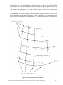
The slab axis system is also illustrated in Figure 4.1. The X" and Y" axes are the stress
reference directions in the plane of the slab, The Z" axis is the slab normal. The X", Y"
and Z" axes form a right handed system. The orientation of these axes within a shell
element structure generally follows the FE system axes at each node. Exceptions are
noted in the appropriate 1-h, system appendix. Stress orientations in a solid element
model are defined by the surface definition in CONCRETE-ENVELOPE or
CONCRETE-CHECK. Refer to the appropriate User Manuals for details.
Note that the NX and MX loads cause stresses in the X" direction, NY and MY cause Y"
direction stresses and NXY and MXY cause shear. The MX and MY designation for
moments should not be confused with the more conventional MXX and MYY designation
for beams, which are defined as moments about each axis, not as moments which cause
stress in each axis.
The sign convention can be altered using the SIGNS command,
Membrane Loads
NX
NXY NXY
NY
Bending Loads
Figure 4.1 Sign Convention for CONCRETE Suite
Contains proprietary and confidential information of ANSYS, Inc. and its subsidiaries and affiliates.
4-2