1
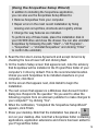
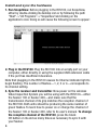
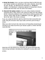
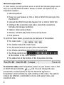
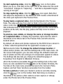
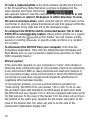
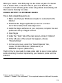
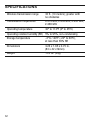
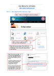
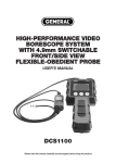
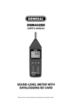
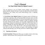
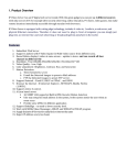
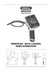
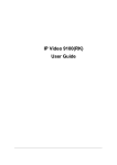
RCV100
USER’S MANUAL
WIRELESS
USB VIDEO RECEIVER
Please read this manual carefully and thoroughly before using this product.
TABLE OF CONTENTS
Introduction . . . . . . . . . . . . . . . . . . . . . . . . . . . . . . 3
Key Features . . . . . . . . . . . . . . . . . . . . . . . . . . . . . 3
Operating Instructions . . . . . . . . . . . . . . . . . . . . . 4
What’s in the box . . . . . . . . . . . . . . . . . . . . . . . . . 4
Anatomy of the RCV receiver . . . . . . . . . . . . . . . . 4
Setup Instructions . . . . . . . . . . . . . . . . . . . . . 4 – 11
Install the software . . . . . . . . . . . . . . . . . . . . 4 – 5
Install and sync the hardware . . . . . . . . . . . . 6 – 7
Normal operation . . . . . . . . . . . . . . . . . . . . . 8 – 10
Wired option . . . . . . . . . . . . . . . . . . . . . . . 10 – 11
Using Skype™*1 to stream video . . . . . . . . . . . . 11
Specifications . . . . . . . . . . . . . . . . . . . . . . . . . . . 12
Warranty Information . . . . . . . . . . . . . . . . . . . . . 13
Return for Repair Policy . . . . . . . . . . . . . . . . . . . 13
2
INTRODUCTION
Thank you for purchasing the RCV100 Wireless USB Video Receiver
from General Tools & Instruments. We strongly suggest that you read
this user’s manual carefully before using the product.
The RCV100 is a plug-in USB device that can wirelessly connect the
Seeker™ 100 or Seeker™ 400 Video Inspection System from General)
to your Windows computer via its USB 2.0 port. The RCV100 also can
be hard-wired to either system’s CameraScope or to the DCS1100
High-Performance Probe-Selectable Video Borescope. Once the
connection has been made, real-time video and still images captured
by the system can be monitored on the computer screen and stored
and processed as well. Uniquely, the RCV100 enables streaming over
the Internet using the Skype™ application. It is a powerful accessory
that troubleshooting technicians, technical trainers and inspection
specialists can use to host video conferences that anyone with Internet
access can attend.
A compact device measuring only 3.26 x 1.65 x 0.74 in., the RCV100
is powered by the USB port it plugs into. The packaged product you
have received contains the receiver along with an installation CD, a
video input cable and a 3-foot long USB extension cable.
KEY FEATURES
• Software is Skype-enabled, allowing streaming of real-time
camera probe video over the Internet
• Works with General’s Seeker 100 and Seeker 400 Video
Inspection Systems and DCS1100 High-Performance
Probe-Selectable Video Borescope
• Compatible with any computer running Windows® 7, Windows®
Vista or Windows® XP on a Pentium IV microprocessor or later
and equipped with at least 2 GB of RAM, a USB 2.0 or 3.0 port
and a CD or CD/DVD drive
• Any of four (4) wireless channels can be selected to maximize
video quality
3
OPERATING INSTRUCTIONS
What’s in the box
The RCV100 USB Wireless Receiver ships with an installation CD, a
video input cable, a 3-ft long USB extension cable and this user’s
manual.
1. Wireless receiver
2. Installation CD
3. USB extension cable
4. Video input cable
1.
2.
3.
4.
Anatomy of the RCV100 receiver
A. USB plug
E.
B. “Connected” light
C. Black CH button for channel selection
D. Power/Channel indicator light; number
of flashes corresponds to channel
numbers from 1 to 4
E. Video in jack
A.
C.
D.
B.
SETUP INSTRUCTIONS
Install the software
1. Place the installation disk CD in your computer’s CD/DVD drive and
close the drawer. After the CD loads, the “Welcome to the Scope
View Setup Wizard” screen will appear. Click Next to continue.
4
(Using the ScopeView Setup Wizard)
In addition to installing the ScopeView application,
you can also use the ScopeView Setup Wizard to:
• Remove ScopeView from your computer.
• Repair errors in the most recent installation by fixing
missing and corrupt files, shortcuts and registry entries
• Change the way features are installed.
To perform any of these tasks, place the installation disk in
your CD/DVD drive and close the drawer. You can also uninstall
ScopeView by following the path “Start”->”All Programs”>”ScopeView”->”Uninstall ScopeView” and clicking “Enter”
to confirm the uninstall.)
2. Read the End-User License Agreement and accept its terms by
checking the box at lower left and clicking Next.
3. On the Custom Setup screen that appears next, note the advisory
that ScopeView will be installed in the ProgramFiles folder of your
computer’s C drive by default. This is the recommended location.
Unless you want ScopeView to be installed elsewhere on your
computer, click Next.
4. On the screen that appears next, click Install to begin the
installation.
5. The next screen that appears is a Windows User Account Control
dialog box. Respond to the question “Do you want to allow the
following program from an unknown publisher to make changes to
your computer?” by clicking “Yes”.
6. When the notification, “Completed the ScopeView Setup Wizard”
appears, click Finish.
7. Show your desktop. Note that the installation has placed a
icon on your desktop. Also note that a ScopeView folder containing
applications, application extensions and drivers has been added to
your ProgramFiles folder.
5
Install and sync the hardware
1. Run ScopeView. Before plugging in the RCV100, run ScopeView,
either by double-clicking its desktop icon or by following the path
“Start”->”All Programs”->”ScopeView”and clicking on the
application’s icon. Doing so will cause the following screen to appear:
2. Plug in the RCV100. Plug the RCV100 into an empty port on your
computer, either directly or using the supplied USB extension cable
if the port has insufficient clearance.
Note that plugging in the RCV100 causes its Channel indicator light to
begin flashing. The number of flashes—1, 2, 3 or 4—corresponds to
its channel setting.
3. Sync the receiver and transmitter. Now power on the wireless
Video Inspection System you will be using with the RCV100—either
the Seeker 100 or Seeker 400—and make sure that the
transmission channel of its grip matches the reception channel of
the RCV100. Both units should be producing the same number of
green flashes. To learn how to power on or change the channel of
the Seeker 100 or Seeker 400, refer to its user’s manual. To change
the reception channel of the RCV100, press the black
CH button on its end as many times as necessary to sync it with
your Seeker.
6
4. Select the Seeker. Once you have confirmed that the RCV100 and
your Seeker system are operating on the same channel, check that
the text “KC362” (for Windows XP computers) or “WDM2861
Capture” (for Windows7 computers) appears in ScopeView’s Device
window (the third item from the left on its toolbar).
5. Deselect the laptop camera. If you are using a laptop computer
equipped with a video camera, the camera is likely to be the default
device. Using the pulldown menu in the Device window, deselect the
camera. select either KC362 or WDM2861, and click
(the
tab to the right of the Device window).
If you are using the RCV100 with the DCS1100, first connect the two
units using the included video input cable and then perform Step 4
above.
When you click Connect, the main screen of ScopeView should begin
showing a live video feed from your Seeker system or DCS1100 that
looks like this:
Note that once the RCV100 is connected, the green LED below the
General logo will light, indicating its readiness to receive video and
photos.
7
Normal operation
In most cases, you will perform some or all of the following steps each
time you use the RCV100 with a Seeker or DCS1100 system for an
inspection session:
• Start ScopeView
• Power on your Seeker or 100 or 400 or DCS1100 and sync it to
the RCV100
• Connect the RCV100 and the Seeker 100 or 400 or DCS1100
• Configure the connection (set video and photo resolutions,
formats and storage locations)
• Capture videos and pictures
• Browse, edit and play back videos and pictures
• Print pictures
To perform these tasks, you will use six features of ScopeView:
• The main menu
• The toolbar below the main menu
• The Preview Pane at the left of the main window
• The Photos and Videos tabs of the Preview Pane
• The Photo Control bar
at the bottom of the main window
• The status bar at the bottom of the ScopeView window
To view live video, start ScopeView, power on your Seeker 100 or 400
or DCS1100 and click the
tab. You can change the size
(horizontal x vertical pixels) of the live feed that appears in
ScopeView’s main window by right-clicking on the video. The options
include ten different combinations of size and aspect ratio, plus
maximum size.
8
To start capturing video, click the
icon on the toolbar.
When you do so, note that on the right side of the status bar the word
“Connected” changes to “Capturing…” and that a stopwatch begins
running at its right.
To stop capturing video, click the
icon again. Note that
this stops the stopwatch on the status bar and creates a thumbnail of
the video just captured in the Preview Pane.
To play back a captured video, click its thumbnail in the Preview
Pane. The video will play from start to finish in the main window over a
video control bar
that indicates both its total duration (at the right) and the current time
position (at the left). Use the play, pause and stop icons to control
playback.
To preview, save, delete, or change the name or storage location
of a captured video, or display its properties, right-click the video’s
thumbnail in the Videos tab of the Preview Pane and left-click the
desired action.
By default, all videos and photos captured by the RCV100 are stored in
a folder called ScopeView that the application creates in your
MyDocuments folder. To change the default storage location of
videos and/or photos, left-click the Settings tab of the main menu. On
the screen that appears, you can also change the default format and
size of photos and the size and type of compression applied to videos.
The Settings tab also lets you change the default language of
ScopeView from English to Mandarin Chinese.
(All of the functions accessible through the Settings tab on the main
menu are also available from the
tab on the toolbar. Similarly, the
Tool tab on the main menu provides access to the Connect, Photo,
Capture and Set Timer functions accessible from the toolbar.
To take a picture of what your Seeker’s probe is currently viewing,
click the
icon on the toolbar. Note that doing so creates a
thumbnail of the picture (often called a screen capture or vidcap)
under the Photos tab of the Preview Pane.
9
To view a captured photo in the main window, double-click its icon
in the Preview Pane. Note that when a picture is displayed in the
main window, the Photo Control bar
also appears below it. Use the controls on the bar to zoom in or out
on the picture or rotate it 90 degrees in either direction. To view
the next or previous photo, either click the right or left arrows on the
control bar or click the yellow directional arrows that appear within the
main window to the right and left of the displayed image.
To configure the RCV100 and its connected Seeker 100 or 400 or
DCS1100 to automatically capture videos and/or photos on a regular
schedule, click the
tab on the toolbar. You can choose a daily,
weekly or monthly schedule, or specify a date and time or a duration
(for a video).
To disconnect the RCV100 from your computer, first close the
ScopeView application. Then click the Safely Remove Hardware and
Eject Media icon on your computer’s system tray and click on “Eject
USB Composite Device.”
Wired option
If the video that appears on your computer is “noisy” (has streaks or
flickering lines running through it), the probable cause is an electrically
noisy environment. With so many electrical and electronic devices in
use everywhere today, many environments in which the RCV100 will
commonly be used have enough electromagnetic interference to
negatively affect wireless signals.
To remedy the problem, you can override wireless operation by
“hard-wiring” the RCV100 to your Seeker 100 or 400. To do so, use
the provided cable with standard mini-RCA plugs at both ends. Both
the RCV100 and your Seeker 100 or 400 are equipped with video ports
for that purpose. In the case of the Seeker 100, the video out port is on
the bottom of the pistol grip, opposite the DC power input jack. In the
case of the Seeker 400, the video out jack is on the side of the
instrument’s detachable display unit.
10
When you insert a mini-RCA plug into the video out jack of a Seeker
100 or Seeker 400, or into the video in jack of an RCV100, the
computer screen showing probe video will go blank momentarily, and
then resume showing live video.
USING SKYPE TO STREAM VIDEO
This is fairly straightforward to do:
1. Make sure that your Windows computer is connected to the
Internet
2. Download the Skype application (be sure it is version
4.2.0.169 or later) from www.skype.com
3. Install the Skype software on your computer, complete the user
profile and set up a Skype account
4. Open Skype
5. Under the “Tools” tab of the main screen, click on “Options”
6. In the left pane of the screen that appears, choose
“Video Settings”
7. On the next screen, under the “Select Webcam” tab,
choose “KC362 USB Video” (Windows XP) or
WDM2861 Capture (Windows 7)
That’s it. You’re now ready to make video calls to one or more parties
while streaming the video captured by your Seeker’s probe over the
Internet.
*1 Skype is a trademark of Skype Limited
*2 Windows® 7, Windows® Vista and Windows® XP are registered trademarks of Microsoft Corporation.
11
SPECIFICATIONS
Wireless transmission range
33 ft. (10 meters); greater with
no obstacles
Transmission frequencies
2.414 GHz, 2.432 GHz, 2.450 GHz,
2.468 GHz
Operating temperature
32º to 113ºF (0º to 45ºC)
Operating relative humidity (RH) 5% to 95%, non-condensing
Storage temperature
-4º to 140ºF (-20º to 60ºC),
at less than 85% RH
Dimensions
3.26 x 1.65 x 0.75 in.
(83 x 42 x19mm)
Weight
1.23 oz. (35g)
12
WARRANTY INFORMATION
The RCV100 Wireless USB Video Receiver from General Tools &
Instruments (General®) is warranted to the original purchaser to be
free from defects in material and workmanship for a period of 1 year.
Subject to certain restrictions, General will repair or replace this
instrument, if after examination, it is determined by General to be
defective in material or workmanship.
This warranty does not apply to damages that General determines to
be from an attempted repair by non-authorized personnel or misuse,
alterations, normal wear and tear or accidental damage. The defective
unit must be returned to General Tools & Instruments or a General
authorized service center, freight prepaid and insured.
Acceptance of the exclusive repair and replacement remedies
described herein is a condition of the contract for purchase of this
product. In no event shall General be liable for any incidental, special,
consequential or punitive damages, or any cost, attorneys’ fees,
expenses, losses alleged to be as a consequence of any damage due
to failure of, or defect in any product including, but not limited to, any
claims for loss of profits.
RETURN FOR REPAIR POLICY
Every effort has been made to provide you with a reliable, product of
superior quality. However, in the event your instrument requires repair,
please contact our Customer Service to obtain a RGA# (Return Goods
Authorization) before forwarding the unit via prepaid freight to the
attention of our Service Center at this address:
General Tools & Instruments
80 White Street
New York, NY 10013
212-431-6100
Remember to include a copy of your proof of purchase, your return
address, and your phone number and/or e-mail address.
13
NOTES
__________________________________________________
__________________________________________________
__________________________________________________
__________________________________________________
__________________________________________________
__________________________________________________
__________________________________________________
__________________________________________________
__________________________________________________
__________________________________________________
__________________________________________________
__________________________________________________
__________________________________________________
__________________________________________________
__________________________________________________
__________________________________________________
__________________________________________________
__________________________________________________
14
NOTES
__________________________________________________
__________________________________________________
__________________________________________________
__________________________________________________
__________________________________________________
__________________________________________________
__________________________________________________
__________________________________________________
__________________________________________________
__________________________________________________
__________________________________________________
__________________________________________________
__________________________________________________
__________________________________________________
__________________________________________________
__________________________________________________
__________________________________________________
__________________________________________________
15
GENERAL TOOLS & INSTRUMENTS
80 White Street
New York, NY 10013-3567
PHONE (212) 431-6100 • FAX (212) 431-6499 • TOLL FREE (800) 697-8665
e-mail: [email protected] www.generaltools.com
RCV100 User’s Manual
Specifications subject to change without notice.
Not responsible for typographical errors.
©2010 GENERAL TOOLS & INSTRUMENTS
12/18/10