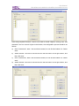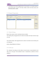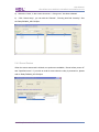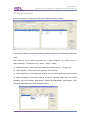
1
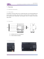
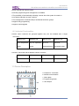
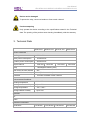
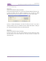
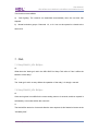
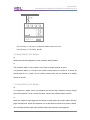
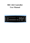
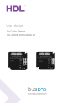
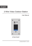
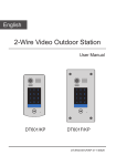
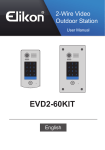
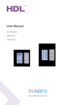
User Manual 10 A Relay Series MR1610.433 MR1210.433 MR0810.432 MR0410.431 www.hdlautomation.com User Manual HDL-MR0410.431/MR0810.432/MR1210.433/MR1610.433 Document updates: Version Date V1.0 2015.01.20 Description Finish new document 10A Relay Series– User Manual User Manual HDL-MR0410.431/MR0810.432/MR1210.433/MR1610.433 INDEX 1. Overview........................................................................................................................................1 1.1 General Information.......................................................................................................... 1 1.1.1 Description...............................................................................................................1 1.1.2 Mounting.................................................................................................................. 1 1.1.3 Serial Numbers.......................................................................................................1 1.2 Functions.............................................................................................................................2 1.2.1 Common Functions................................................................................................2 1.2.2 Individual Functionalities.......................................................................................3 1.3 Device Description.............................................................................................................3 1.4 Recommend Load Types................................................................................................. 4 2. Safety Precautions.......................................................................................................................4 3. Technical Data.............................................................................................................................. 5 4. Installation..................................................................................................................................... 6 4.1 Wiring...................................................................................................................................6 4.2 HDL BUS Pro Description................................................................................................ 6 4.3 Commissioning...................................................................................................................7 5. Software Configuration............................................................................................................... 8 5.1 Basic Settings.....................................................................................................................8 5.1.1 Changing the Device ID........................................................................................ 8 5.1.2 Remarks...................................................................................................................8 5.2 Area Setup.......................................................................................................................... 8 5.3 Channel Parameters.......................................................................................................10 5.3.1 Default Settings....................................................................................................10 5.3.2 Load Type..............................................................................................................10 5.3.3 Load Testing..........................................................................................................11 5.4 Scene Setup..................................................................................................................... 11 5.4.1 Scene Settings......................................................................................................11 5.4.2 Scene Restore......................................................................................................12 5.5 Sequence Setup.............................................................................................................. 13 6. New Functions............................................................................................................................15 7. FAQ.............................................................................................................................................. 16 8. NOTES........................................................................................................................................ 19 10A Relay Series– User Manual User Manual HDL-MR0410.431/MR0810.432/MR1210.433/MR1610.433 1. Overview 1.1 General Information 1.1.1 Description This intelligent 10A relay module uses a 16A launching relay, to provide high reliability and ultra-low power consumption. With a HDL Bus Pro interface based on the RS485 protocol, and integrated scene controller.With manual bypass control, the module is the perfect relay solution. 1.1.2 Mounting Standard 35mm Din Rail Installation Inside Distribution Box(DB) 1.1.3 Serial Numbers 10A Relay Series– User Manual User Manual HDL-MR0410.431/MR0810.432/MR1210.433/MR1610.433 MR0410.431 MR0810.432 4 Channels 8 Channels Max. 10A per channel Max. 10A per channel Max. 40A total Max. 80A total MR1210.433 12 Channels Max. 10A per channel Max. 120A total MR1610.433 16 Channels Max. 10A per channel Max. 160A total 1.2 Functions The universal relay series have a number of programmable features, these features are listed below. 1.2.1 Common Functions Ability to control scenes Each area has 2 sequences, with each sequence having 12 steps Each channel has a light protection delay (0-60 minutes) Each channel has a batch turn-on delay(0-25 seconds) 10A Relay Series– User Manual User Manual HDL-MR0410.431/MR0810.432/MR1210.433/MR1610.433 Each channel has manual control Remote The LED The programming and management is available possibility of automatically activating a scene when the system is turned on status indication for each channel management of staircase lamps and Mutual exclusion groups Support easy programming Support online upgrade 1.2.2 Individual Functionalities When channels are grouped together they can be modified with a single Areas- command. MR0410.431 MR0810.432 MR1210.433 MR1610.433 Up to 4separated Up to 8 separated Up to 12 Up to 16 areas areas separated areas separated areas Scenes –Each relay has a different number of scenes MR0410.431 MR0810.432 MR1210.433 MR1610.433 Up to 8 scenes Up to 16 scenes Up to 24 scenes Up to 32 scenes 1.3 Device Description a. Outputs for 4 channels b. Manual control buttons c. Name plate d. Programming button e. HDL-Buspro 10A Relay Series– User Manual User Manual HDL-MR0410.431/MR0810.432/MR1210.433/MR1610.433 1.4 Recommend Load Types Type power Motors: 1HP(1HP=746W) Incandescent lamp load 1600 W Inductive transformer 1000 W Electronic transformer 800 Halogen lamp 1600 W 230 V W Mercury-vapor lamp * Uncompensated luminaire 1000 W * Parallel compensated 800 W Fluorescent lamp T5 / T8 * Uncompensated luminaire 1000 W * Parallel compensated 800 W * DUO lamp 800 W Dulux lamp * Uncompensated luminaire 1000 W *Parallel compensated 800 W 2. Safety Precautions Danger Serious injuries, fire or property damage possible. Please read and follow safety all precautions fully. Risk of fatal injury from electrical current All work on the device should only be carried out by trained, and qualified electricians. Before working on the device, or before exchanging light bulbs, disconnect mains voltage and switch off circuit breakers. 10A Relay Series– User Manual User Manual HDL-MR0410.431/MR0810.432/MR1210.433/MR1610.433 Device can be damaged To protect the relay, connect a breaker or fuse to each channel. Product tampering Only operate the device according to the specifications stated in the Technical data. The opening of the products outer housing immediately voids the warranty. 3. Technical Data MR0410.431 MR0810.432 MR1210.433 MR1610.433 Electric Parameter : Working power DC24~30V Static power consumption 15mA/DC24V Dynamic power consumption 40mA/DC24V Output channel 4CH/10A Relay 16A Magnetic latching relay Max current in each channel Electronic life time of relay 8CH/10A 12CH/10A 16CH/10A 10A >60000 (Resistance Load) Protection Connect a breaker in each channel Environmental Conditions: Working temperature 0℃~45℃ Working relative humidity Up to 90% Storage temperature -20℃~+60℃ Storage relative humidity Up to 93% Approved CE RoHS Production information: Dimensions 72×90×66 10A Relay Series– User Manual 144×90×66 216×90×66 216×90×66 User Manual HDL-MR0410.431/MR0810.432/MR1210.433/MR1610.433 Weight 252(g) Housing material Nylon, PC Installation 35mm Din Rail installation Protection degree 361(g) 645.5(g) IP20 4. Installation 4.1 Wiring Please strictly follow the wiring diagram shown below. N L Load Air breaker 4.2 HDL Buspro Description Connector Information Buspro DC24V Red COM Black DATA- White DATA+ Yellow 10A Relay Series– User Manual 605(g) User Manual HDL-MR0410.431/MR0810.432/MR1210.433/MR1610.433 4.3 Commissioning Method One: a) Open the HDL-BUS Pro Setup tool software. b) Press the programming button for 3 seconds, the LED status indicator will then turn red. c) Using the software, click the “Address management” tab, and select the “Modify address (when device button is pressed)”, the window shown below will then appear: d) Click on “Indicate initial address”, the device ID will then be shown. If you wish to change the address, enter your modification and click “Modify initial address”. Clicking on the “+Add” tab will include the device in the online devices list. Method Two: a) Open the HDL-BUS Pro Setup tool software. b) Click the search button, and a new window will appear. From this window click “Search the online devices”, then click the “Add all” tab. The device will then be included in the online devices list. 10A Relay Series– User Manual User Manual HDL-MR0410.431/MR0810.432/MR1210.433/MR1610.433 5. Software Configuration 5.1 Basic Settings 5.1.1 Changing theDevice ID Every HDL BUSpro device has one Subnet ID, and one Device ID. The device ID should be unique in its subnet, and be kept consistent with the Gateway (typically the SB-DN-1IP or HDL-MBUS01IP.431). 5.1.2 Remarks To aid trouble shooting, and to assist in future modifications it is recommended that a general description is included. As an example if it is to be used in a living room set the remark as “For Living Room”, if it is for distribution box 3 set the remark as “For DB3”. 5.2 Area Setup The below screen shot shows all 4 channels from the relay, these channels have not been assigned to any area. 10A Relay Series– User Manual User Manual HDL-MR0410.431/MR0810.432/MR1210.433/MR1610.433 If the wiring required Channels 1 and 2 to be used to control 2 lights in a living room, and channels 3 and 4 to control 2 lights in the kitchen, the configuration process would be as follows: a) Click “Create area”, area 1 has now been created, we can find and select it in “Select area”. b) Select channel 1 and 2 then move them from the left column to the right column, and then click save. c) Click “Create area”, area 2 has now been created, we can find and select it in “Select area”. d) Select channel 3 and 4 then move them from the left column to the right column, and then click save. 10A Relay Series– User Manual User Manual HDL-MR0410.431/MR0810.432/MR1210.433/MR1610.433 e) As all channels have been assigned areas, there should be no channels present in the left hand column. Exit the “Area setup” window, and the two areas, (living room and kitchen) will be created. 5.3 Channel Parameters 5.3.1 Default Settings Delays- Both a power on and a switching delay are included The switching delay is triggered when the channel is activated, the delay time has a range of 0~25s. The protection delay is also triggered when the channel is activated, but has a delay time of 0~60minutes. (See the RelayFAQ006_HDL-BUSpro) 5.3.2 Load Type The “Load type” has nothing to do with either the control method, or output behavior of the relay. If the “Load type” is left unselected it has no overall effect, by default it is left as undefined. 10A Relay Series– User Manual User Manual HDL-MR0410.431/MR0810.432/MR1210.433/MR1610.433 5.3.3 Load Testing Before configuring the end user panel, the below window can be used to trigger the Dimmer/Relay and to check the wiring. If the “Start test” tab is clicked, Channel 1 with the device ID of 42, will begin to flash every 2 seconds. After the channel test has been confirmed click “Stop test” and then “Turn off load”. 5.4 Scene Setup 5.4.1 Scene Settings Different relays have different numbers of scenes. Scene 0 is always reserved by the relay, to provide an “all off” function, as such it cannot be edited. The remaining scenes are editable however, to modify them follow the steps below: 10A Relay Series– User Manual User Manual HDL-MR0410.431/MR0810.432/MR1210.433/MR1610.433 a) Select the “Area”, in the screen shot area “1- living room” has been selected. b) Click “Scene setup”, you can edit the “Remark”, “Running time”and “Intensity”. See the RelayFAQ002_HDL BUSpro. 5.4.2 Scene Restore When the scene restore tab is clicked, two options are available, “Scene before power off” and “Specified scene”. If you wish to recall a scene when the relay is powered on, please refer to RelayFAQ003_HDL BUSpro. 10A Relay Series– User Manual User Manual HDL-MR0410.431/MR0810.432/MR1210.433/MR1610.433 5.5 Sequence Setup Each area supports 2 sequences, with each sequence having 12 steps. If we wish to create an area that that has an endless sequence, we would follow the below steps. step1 (channel 1 on) -> step2 (channel 2 on) -> step 3 (channel 1 on; channel 2 on) -> step4 (channel 1 off; channel 2 off)-> step1 -> step2 -> step3…… a) Select the “Area”, in the screen shot below the selected area is “1- living room”. b) Click “Remark”, we can name the sequence “flow-nonstop”. c) Click “Sequence”, as 4 scenes are required, one for each step,and we want to create an endless sequence, the below settings should be followed. There are four modes available, they are Forwards, Backwards, Forwards and Backwards, and Random. (The sequence described above is the forwards mode.) 10A Relay Series– User Manual User Manual HDL-MR0410.431/MR0810.432/MR1210.433/MR1610.433 d) Double clickon the “Step” tab, and the below window will appear. According to the effects, the 4 scenes we need for each step are scene1, scene3, scene2, and scene0. The “Step time” is the delay time taken between the activation of different steps or scenes. Typically the step time is higher than the running time of the scene, below the time is set at 0.5s longer than the running time of each scene. 6. New Functions 10A Relay Series– User Manual User Manual HDL-MR0410.431/MR0810.432/MR1210.433/MR1610.433 Two functions are available: a) Stair lighting: The channel can deactivate automatically when the set time has elapsed. b) Mutual exclusion groups: Channels 1-2, or 3-4 can not be opened or closed at the same time. 7. FAQ 7.1 RelayFAQ001_HDL BUSpro Q: What does the “load type” tab in the HDL-BUS Pro Setup Tool refer to? Can it affect the behavior of the relay? A: The “load type” tab in no way affects the operation of the relay, it is simply a remark. 7.2 RelayFAQ002_HDL BUSpro Q: If the running time is modified in the scene setting menu to 3 seconds, and then a panel is activated by a user what will be the outcome? A: The load will be turned on 3 seconds after the user requests it, this feature is known as the “ON-delay time”. 10A Relay Series– User Manual User Manual HDL-MR0410.431/MR0810.432/MR1210.433/MR1610.433 7.3 RelayFAQ003_HDL BUSpro Q: What conditions need to be met to trigger the scene restore function? A: Triggering the scene restore function can be achieved by selecting “Scene before power off” or “Specific scene”. If “Specific scene” is selected the scene will be activated automatically when powered on. If “Scene before power off” is selected then the channel must have been active for at least 20 seconds before the power was turned off, if the scene used by the relay is to be restored. Additionally, if the Relay was playing a sequence, the relay will play the sequence when it is powered on again. 7.4 RelayFAQ004_HDL BUSpro Q: If a button is pressed on the user panel, but the indicator LEDs on the Relay module and user panel do not change, or the load stays on, what could the problem be? A: If the unit fails to respond to commands, and the status indicators do not change, it is likely that a component has malfunctioned. To remedy this if the module is under warranty contact our sales team for an exchange, or if you wish to fix the module yourself we will ship the relevant components. 7.5 RelayFAQ005_HDL BUSpro Q: If a relay channel is broken, and cannot be turned on or off, can the module be temporarily used? A: Yes if you have pre-wired two manual switches to the relay channel as the below diagram shows. 10A Relay Series– User Manual User Manual HDL-MR0410.431/MR0810.432/MR1210.433/MR1610.433 Turn on Lamp 1: Turn on S1, it does not matter if S2 is on or off. Turn off Lamp 1: Turn off S1 and S2 7.6 RelayFAQ006_HDL BUSpro Q: What is the practical application of the protection delay feature? A: The protection delay is very simple to use, below a simple example is given: If a protection delay of 1 minute is set, and the relay channel is turned off, it cannot be turned back on for 1 minute. This is useful for loads which are not suitable to be rapidly turned on and off. 7.7 RelayFAQ007_HDL BUSpro Q: In a sequence a bright scene was assigned as the last step, instead of staying ‘bright’ when the sequence is over it turned ‘full dark’. What is the possible reason for this? A: When the sequence was triggered, the dimmer module saves the current status and then plays the sequence. When the sequence is over the dimmer reverts to its previous status, thus it is likely that the status was ‘full dark’ before the sequence was triggered. 10A Relay Series– User Manual User Manual HDL-MR0410.431/MR0810.432/MR1210.433/MR1610.433 8. NOTES .............................................................................................................................................. ............................................................................................................................................... ............................................................................................................................................. .............................................................................................................................................. .............................................................................................................................................. .............................................................................................................................................. .............................................................................................................................................. ............................................................................................................................................. .............................................................................................................................................. .............................................................................................................................................. .............................................................................................................................................. .............................................................................................................................................. .............................................................................................................................................. .............................................................................................................................................. .............................................................................................................................................. .............................................................................................................................................. .............................................................................................................................................. .............................................................................................................................................. .............................................................................................................................................. .............................................................................................................................................. .............................................................................................................................................. .............................................................................................................................................. .............................................................................................................................................. .............................................................................................................................................. .............................................................................................................................................. .............................................................................................................................................. 10A Relay Series– User Manual