1
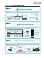
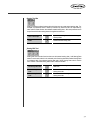
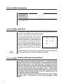
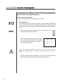
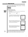
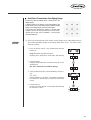
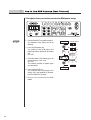
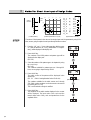
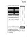
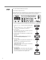
R
USER S MANUAL
FOR DESIGN INPUT
KM-2070P
lity
a
u
tQ
Besst Pricevice
Be st Ser
Be
1. Thank you for purchasing our product. Based on the rich expertise and
experience accumulated in industrial sewing machine production, SUNSTAR
will manufacture industrial sewing machines, which deliver more diverse
functions, high performance, powerful operation, enhanced durability, and
more sophisticated design to meet a number of user’s needs.
2. Please read this user’s manual thoroughly before using the machine. Make
sure to properly use the machine to enjoy its full performance.
3. The specifications of the machine are subject to change, aimed to enhance
product performance, without prior notice.
4. This product is designed, manufactured, and sold as an industrial sewing
machine. It should not be used for other than industrial purpose.
R
SunStar CO., LTD.
Contents
1. Design Input for KM-2070P
1) Design Input for KM-2070P
■Serial Transmission Method Using SSPz
■Direct Input of User-Generated Codes
■Provision of User-Requested Designs by Sunstar
2. Guidelines for Using SSPz
1) Before Using
2) Principal Parts
3) Accessories
4) System Requirements
5) Installing the Program
■Program Installation(Unavailable for Windows 95)
3. Getting Started
1) Introduction
2) Start and Finish of Program
2) Caution
4. Configuration of Program Function
1) Program Operation Flow
2) Edit Window
3) Meun Bar
4) Tool Bar
5) Status Bar
6) Sub Tool Bar
5. Data Configuration
1) Data Construction
2) Sewing Data
3) Jump Data
4) Selection of Elements Using the Mouse
6. Data Creation
1) Creation of Sewing Data
■Data Input by Using the Mouse
■Data Input by Using the Direction Key on the Keyboard
■Data Input by Using the Numeric Keys on the Keyboard
6
7
7
7
7
8
9
9
10
10
11
11
14
14
15
16
17
18
19
20
21
24
24
26
27
28
28
28
29
30
30
31
31
7. Edit Function
1) Editing Sewing Data
■Editing with the Mouse Pointer
■Editing with the Keyboard Direction Key
■Editing by Input Value of the Keyboard
■Editing by the Sequence of Stitch Creation
8. Data Processing
1) Other Useful Functions
■Edit Tools
■Enlarge/Reduce, Rotate, Move, Mirror
■View Max./Min Sewing Area
■Measurement of the Length Between Two Stitches
2) Sewing Setup
■Setting Up the Sewing Range
■Setting Up the Sewing Data Range
■Stitch Points Layout
4) Copy & Paste
9. Pattern Data Input/Output
1) Save/Open Files
■Save Files
■Save 2070P Files
■Open Files
2) Port Setting of User’s Computer
3) Serial Transmission of the Zigzag Design and the ROM Data
■Serial Direct Transmission of the Zigzag Design
■Serial Transmission of ROM Data
32
33
33
34
34
34
37
38
38
42
44
45
46
46
47
48
49
50
51
51
52
52
53
54
55
55
10) Guidelines for User Input of Pattern Codes
59
1) How to Use ROM Patterns(User Patterns)
2) Structure of Input Pattern Data
3) Method for Direct User Input of Design Codes
4) Example
5) Actually Sewed Sample Design (Basic Patterns)
60
61
64
67
73
11) Method of setting the starting point
74
1
Design Input for KM-2070P
Currently there are three methods available for design input using
KM-2070P. Please refer to the following methods for an easier input of designs.
NO. Examples of Input Methods
6
1
Serial Transmission Method Using SSPz (refer to p. 6)
2
Direct Input of User-Generated Codes (refer to p. 6)
3
Provision of User-Requested Designs by SunStar (refer to p. 6)
1
Design Input for KM-2070P
Support 1
Serial Transmission Method Using SSPz
Serial Transmission of Pattern Designs Using SSPz, the Input Program Designed for the Exclusive Use of KM-2070P
SSPz Free Version
Download at the M/C by
Method of Serial Transmission of the Generated
Pattern Data
Serial transmission of ROM data
in Input Instruction Manual for
KM-2070P.
Support 2
Method for Direct User Input of Design Codes
Refer to method for direct user input of design codes in Input Instruction Manual for KM-2070P.
1)
2)
Visual
Generation
of Patterns
Using SSPz
Direct Generation
of Pattern Codes
by the User
Support 3
9 - 0 1
n
1
2 5
4 0
SSPz automatically crea-tes
the pattern data code list in
text file format.
Enter the data for
each stitch using
the input button
on the OP Panel
referring to the
pattern code list
generated by the
user or SSPz.
.
.
Generation of pattern codes
requires the user’s understanding of the mechanical
transfer of the presser foot
and data coord-inates.
n
Input of Pattern Codes
Using the Combination
of the Above Keys
3 5
4 0
.
E n d
Provision of User-Requested Designs by SunStar
In the case of peculiar designs or those that cannot be input by using the above methods, SunStar examines and
provides those designs requested by the user.
Buyers or end users request
designs.
SunStar generates requested designs.
SunStar provides requested
designs in an expansion ROM.
Buyer or End User
7
2
Guidelines for
Using SSPz
8
2
1
Before Using
Check the followings prior to setting up the program and components.
2
Principal Parts
Dial O/P
KM-2070P-7
Serial Transmission Port
Rear Panel of the Computer
Connection Port for
Serial Transmission
Cable
Serial Cable
Feed Adjustment
Dial
Condenser Adjustment Value Display
Feed Adjustment
Value Display
Condenser
Adjustment Dial
Dial Control Box
Computer
[Connection Configuration of Serial Cable]
Connect the serial transmission cable provided with the product between the serial
connection jack of the computer and the serial transmission cable connection jack on the dial
control box.
9
3
Accessories
① Install CD
Manual
② Manual
③ Serial Cable
4
System Requirements
Prior to installing the program on the user PC, check if the system satisfies the following
requirements.
PC
IBM - PC or Compatible Types
CPU
Pentium PC or Higher Version
OS
Windows 98 / 2000 / XP
Memory
32M or More (64M or more is recommended)
Hard disk free space 50M or More
Display
10
VGA or Higher Version
(256-color SVGA or a higher version is recommended)
Serial Port
Port used for the transmission of the zigzag data file to 2070P
Mouse
Mouse for Windows
Printer
Printer that supports Windows
5
Installing the Program
■ Program Installation (Unavailable for Windows 95/2000/XP)
① The OS of the computer used for this program should be Windows 98 version.
② Insert the installation CD in the CD-ROM and double-click the execution file marked with
“Setup”in the Disk 1 folder.
③ Upon getting the InstallShield Wizard window displayed, click Next.
④ When the software license agreement window is displayed, click Yes.
11
⑤ The Choose Destination Location window is displayed. If you want to change the
location, select your desired folder by clicking the Browse button. And click Next for the
nest step.
⑥ Program installation will start on the screen.
⑧ Click Finish when the installation is completed.
12
⑨ If you can find the installed program registered in the program list of the Start Menu, the
installation is successfully completed.
If the program is successfully installed, double-click“SunStar Machinery Co., Ltd.”where
the program is installed. You can find the“SunStar SSPZ”folder in the folder. Double-click
“SunStar SSPZ”to confirm the following icons.
13
3
Getting Started
Introduction
This manual explains the input program of electronically controlled high-speed
1-needle zigzag sewing machines in connection with KM-2070P. It is designed
to help the user easily create, edit and manage sewing data. This manual is
the official user manual that contains overall information on the installation and
actual use of the program. Please read this manual thoroughly from the
beginning to the end before using the program.
14
1
Start and Finish of Program
After installing the program on your computer, connect your computer with
KM-2070P using the serial cable provided with the product (Refer to
“ Principal Parts”
”of this manual). The program is located in the directory
chosen by the user when it was installed. You can find the program
registered in the program list of the Start Menu as in the following figure
”of this manual).
(Refer to“Installing the Program”
[Ex: Start Menu - Program - SunStar SSPZ - SSPZ]
① To execute the program, click SSPz registered as shown in the figure or double-click the
execution file in the folder where the program is actually installed.
② As the SSPz program is executed,
Start Dialog is displayed as in the
left picture. Click Start to start the
program.
③ To finish the program, select Exit
in the file menu or click the close
button on the upper-right corner
of the program screen after
saving the files.
15
2
Caution
The following is an important explanation/instruction the user should abide
by while using the program. Please thoroughly read and understand the
followings.
① This program provides functions with which the user can create and edit sewing data using
the direction keys on the keyboard. Before using the program, you must understand one
thing very important, which is related with the screen mode. The program is set up to
automatically configure its window size to your monitor size. In the case of inputting or
editing data using the direction keys on the keyboard, if you execute the program after
changing the default window size, you will get an unconformity of mapping between the
program and the Windows screen. Thus it should be noted that if you change the window
size of the program, the input operation by using the direction keys may not work properly.
That is, you can still input data, but the coordinates of the inputted data will deviate from the
actual location by 0.2~0.3mm. In this case, however, data input by using the mouse point
works well without deviation.
② Sewing data 127 or more stitches should not be created in one pattern. When created
sewing data are transmitted to 2070P, the data of one stitch are divided into the corrdinate
value of the x-axis and the transfer value of the y-axis before the value of the total number
of stitches is transmitted. Therefore, transmitting 127 or more stitches would cause a
problem. Please keep this in mind when creating sewing data.
③ In the case of the starting point when a design is created, a jump is automatically created from
the origin to the first point. Therefore, you should not create another jump
data except the first jump when making a design.
Correct Design
④ In connection with using the Zoom In/Zoom Out tool, a
message box will be displayed, and the screen will not
get bigger any more if you zoom in the screen beyond
the maximum. If you continue to zoom in the screen
under this situation, you may lose the data existing on
the screen. Thus in this case, you need to avoid
zooming in and to zoom out the screen using the Zoom
Out tool. At the same time, if you zoom out the screen
until the on-screen data is illegible, the program may
stop. Thus you need to avoid zooming out to an
excessive extent. Please keep this suggestion in mind.
16
Wrong Design
4
Configuration of
Program Function
17
1
Program Operation Flow
The flow chart below illustrates the general flow of the program from Start to
Finish.
Start
Open Data
Create New Edit
windows
Read Sewing Data to Edit
Create Desired
Designs
Determine Sewing Sizes at
Discretion
Finish
Edit Design
Save Design
ZigZag Input Data
List (*.txt file)
Serial Direct
Transmission of
zigzag design
Serial Transmission of ROM
data(ROM.zig)
Serial Transmission
Finish
18
Design Data
(SSP Pattern
Shared)
2
Edit Window
■ Edit Window
The following figure shows the entire configuration of the program and
edit window. All the input and edit works are executed in this window.
Menu Bar
Tool Bar
Edit Screen
Sub Tool
Origin
Mouse Coordinate
Stauts Bar
When the mouse is positioned on the Menu Bar, Sub Tool Bar or Tool Bar, a message is
displayed on the Status Bar to inform the user of the next step. You can operate the program
by left-clicking the edit window to input data in it according to the message, and by creating or
editing data depending on the execution of the Dialog Box (Currently, messages displayed on
the Status Bar are partially supported).
19
3
Meun Bar
■ Menu Bar includes the following functions.
Menu Bar includes each of the Tool Bars and the entire function items of the
program. Refer to the following tool bars for detailed information.
20
File
Close
Save
Save Zigzag
Print
Print
Preview
Printer
Setup
Exit
Serial Transmission
Serial Transmission of
ROM Data
View
Tool Bar
Status Bar
Tool Bar Dialog
Control Bar
Stitch Point On/Off
Zoom In
Zoom Out
Sewing Range
Information on
Window Device
Data Order
Min/Max Sewing Range
Grid Line Setting
Measurement
Measurement of the
Length between two
stitches
Sewing Settings
Sewing Range
Sewing Data Range
Stitch Points Layout
Help
About SSPz
Serial Direct
Transmission of Zigzag
Design
Edit
Copy
Paste
Enlarge / Reduce
Rotate
Move
Mirror
Input Device
Keyboard Input
Keyboard Input (Insert/Move)
Setup Keys
Select User PC
4
Tool Bar
■ Tool Bar provides a variety of functions provided in the menu in a userfriendly manner by buttons.
And Sub Tool Bars are included in it. It displays information on various conditions including, for example, input coordinates displayed on Status Bar and the
total number of created stitches.
·Standard Tool Bar
Provides functions of those items related to file input/output.
Open Files
Reads saved data files
Save Files
Saves data existing on the edit screen
Save Zigzag
Saves data for zigzag (*.txt)
Transmit Serial Data
Performs serial transmission of zigzag data
(ROM.zig) to the 2070P machine.
Design Direct
Transmission
Transmission of the zigzag design to the 2070
machine through the direct serial.
Copy
Copy the selected data.
Paste
Pastes copied data
Print
Prints data existing on the edit screen copy the
selected data.
Delete All
Deletes all the data existing on the edit screen
21
·Measuring Tool Bar
Provides functions to change selected sewing data into various types.
Enlarge/Reduce
Enlarges or reduces selected data
Move
Moves selected data
Rotate
Rotates selected data
Mirror
Turns selected data into a mirror image
Stitch Off
Hides all stitch points on the screen
Stitch On
Shows all hidden stitch points again on the
screen
Measure Ment
Measure the distance between two stitches.
Information
Provides information on selected sewing data
·Replay Tool Bar
Displays and selects the sequence of the sewing data created on the screen. (In the case
of edit, it displays the sequence of created sewing data points.)
22
First Pointer
First: Selects the first data group (Edit: Moves to
the first point)
Previous
Selects the previous data group (Edit: Moves to
the previous point)
Next
Selects the next data group (Edit: Moves to the
next point)
Last
Selects the last data group (Edit: Moves to the last
point)
·Information Tool Bar
Displays the total number of stitches of the created sewing data, information on the
location of data inputted on-screen in absolute or relative coordinates, and distance
measured between two stitches using its measuring function.
Total Stitches
Displays the total number of stitches displayed on-screen.
Absolute/Relative
Displays the absolute/relative coordinates of the inputted stitch.
Stitch Length
Displays the distance measured between two stitches.
·Sewing Command Tool Bar
The Grid Line function displays lines in a grid shape on the edit screen (F2 Key). If
Automatic Point is selected instead of Grid Line, points are automatically inputted where
lines are overlapped.
23
5
Status Bar
Status Bar is located at the bottom of the Windows program.
·Information Status Bar
The user inputs sewing data stitch by stitch
Information Status Bar is located at the lower-left corner of the screen. It provides
appropriate information when buttons or programs are used. The above information is
displayed when the“User’s Stitch Input”button is selected.
·Mouse Coordinates Status Bar
Mouse Coordinates Status Bar displays the coordinates where the mouse pointer is
located when the mouse moves on the edit area. The user can input data using these
coordinates.
6
Sub Tool Bar
The following tool bars including Edit, Sewing and Sewing Edit tool bars
provide actual punching-related functions. All the works related with
punching are performed with these tool bars for the most part.
·Edit Tool Bar
When data are inputted in the current sewing area, Edit Tool Bar provides a variety of
functions for the user’s convenience. It provides the Zoom In/Zoom Out function that can
enlarge or reduce the displayed sewing area. And using the Hand tool in it, the user can
freely move the enlarged sewing area. It also provides the Grid Line function which
enables the user to easily input data by showing the sewing area in a divided grid-shape
pattern.
24
Hand Tool
Moves the sewing area enlarged by the Zoom In
function. (Short F3)
Zoom In
Enlarges the sewing area. (Short F4)
Zoom Out
Reduces the sewing area. (Short F5)
Adjust
Adjusts the sewing area to the sewing size.
Grid Line
Displays grid lines on the sewing area.
(Short F2)
·Sewing Tool Bar
Sewing Tool Bar provides functions with which the user can create actual sewing data. For
example, it provides the User’s Stitch Input function by which the user can input stitch by
stitch and the Delete function that deletes created sewing data. All these processes are to
be performed while the sewing data to be applied are selected.
User’s Stitch Input
Inputs the sewing data of a stitch using the
mouse pointer.
Delete
Deletes selected sewing data.
·Sewing Edit Tool
Sewing Edit Tool includes functions that can edit created sewing data. Add Sewing Data
Node is used to add a stitch in the selected point of sewing data while Delete Sewing Data
is to delete a stitch from selected sewing data node. Move Sewing Data node is used to
move a stitch of selected sewing data node to a different location.
Add Sewing Data Node
Adds a stitch of sewing data in selected sewing
data node.
Delete Sewing Data
Node
Deletes a stitch of sewing data from selected
sewing data node.
Move Sewing Data
Node
Moves a stitch of sewing data from selected
sewing data node.
25
5
Data Configuration
26
5
1
Data Construction
The patterns of data consist of only point stitches. The following figure
shows created data for a simple flower shape. In the case of the 2070P
zigzag machine, the boundary value on the y-axis is infinite. However, the
maximum boundary value on the x-axis is 8mm. The user should keep this
boundary value in mind when creating data.
Edit Frame
+y-axis
Point Stitch
+x-axis
Origin
-y-axis
Edit Frame
[Date Creation]
27
2
Sewing data
User’s Stitch Input
The user can directly input stitch by stitch. The above figure shows the sewing data inputted
by User’s Stitch Input.
3
Jump Data
If two different sewing data exist, there always exist jump data between the
two data. The jump data is automatically created.
As in the left figure showing data creation, a jump is
always created automatically from the origin when the
user initiates sewing data. The figure also shows that
jumps are automatically created between each
section of sewing data. When sewing data is deleted,
the jump data is automatically deleted, and then a
new jump is created between the deleted sewing data
based on the adjacent sewing data that exist before
and after the deleted sewing data. Jump data cannot
be edited and always take the shape of gray dotted
lines.
As above-mentioned, do not create other jump data except the one located at the
initial sewing point from the origin when creating data using 2070P.
4
Selection of Elements Using the Mouse
It is simple to select elements by using the mouse. You need to select the
stitch of data in order to select sewing data. And you know that the stitch
(node) of sewing data is each of the stitch data. The stitches of selected
data are in the shape of a circle while sewing data is displayed in red and in
black that represents stitch data. As for the principle of selecting sewing
data, the pointed location should be within 3 pixels ~ +3 pixels both
vertically and horizontally of the target sewing data to be selected. When
the distance between certain two data is 0.1mm, the neighboring point can
be selected instead of the desired point.
In these cases, the problems will be solved if you set up the 2 setting
”in the menu of“ set up a selecting range of sewing
ranges to be“ 0”
”.
data”
28
6
Data Creation
29
1
Creation of Sewing Data
You can input data by selecting, on the Sub Tool Bar, the function buttons
corresponding to your desired type of input. The following part explains the
creation process of sewing data step by step.
■ Data Input by Using the Mouse
You can input data using the left and right buttons of the mouse.
· User’
’s Stitch Input
In connection with the method of User’s Stitch Input, a jump is automatically created from
the origin when the User’s Stitch Input data are initially inputted. When sewing data
having certain attributes are initiated, jumps are automatically connected centering on the
origin.
① Select the User’s Stitch Input button as shown in the above picture (The
button becomes sunken when selected).
② Locate the mouse pointer in the edit area to input
data. Left click the desired location. And input data.
(Until the User’s Stitch Input function is finished, you
can continuously input data.)
Make sure the distance between each point on the Y-axis shall not be over
2.5mm when inputting data. The maximum transmission width on Y-axis is
2.5mm.
③ Right-click the mouse to finish inputting data. If you want to cancel the inputted data
before right-clicking the mouse, press the Esc button on the keyboard.
30
■ Data Input by Using the Direction Key on the Keyboard
Basically, this method is the same with the data input by using the mouse. The difference
is that this method moves the cursor using the direction keys on the keyboard instead of
the mouse. And it uses the space bar instead of the left button of the mouse when
inputting data. For example, select the User’s Stitch Input button on the Sub Tool bar to
input desired type of sewing data (same with the input by the mouse). Once the button is
selected, locate the mouse in the sewing area. The mouse cursor moves according to the
selection of the direction keys. Once you get the cursor on the exact location where you
are going to input, hit the space bar to input the data. The cursor is designed to move by
1 pixel (0.1mm) when controlled by the direction keys. You can change the movement
distance by selecting the Key Movement Settings among the Input Device items on the
Menu. If you want to make it move by 1mm, set the settings for“10 pixel”. As is
mentioned above, however, this is possible only when the window screen is maintained in
the same way as the initial settings. In the above picture, the Monitor Resolution item is
used to set up the resolution of the monitor. You don’t have the set it up since it is
established automatically. Right-click the mouse when you want to finish inputting data.
The End key on or around the direction keys plays the same role with the right button of
the mouse. (This is useful for elaborate works such as editing stitches.)
■ Data Input by Using the Numeric Keys on the Keyboard
For using the numeric keys for inputting data, click“User’s Point Input by Function
Buttons”on the Sub Tool bar. And select Keyboard Input from the Input Device item in
the menu. Upon selecting it, you will see the Keyboard Input Dialog box displayed onscreen. Enter your desired coordinates in the x- and y-axes and click the Create button as
shown in the picture. And you will see that data are inputted on the screen. To finish
inputting data, click the Close button. In the meantime, the Cancel and Previous buttons
can be applied in the middle of input: the Cancel key provides the same function with the
aforementioned Escape key while the Previous key provides the function with which you
can delete the inputted data point by point.
31
7
Edit Function
There are three methods available for editing data: the first one is using
the mouse buttons for edit, the second one using the direction keys and
the third one by means of the input value. Accordingly, in the case of
the existing sewing data, the data and points can be changed by using
such functions as Add, Delete and Move.
Sewing data should be in the edit area to apply the edit function.
32
1
Editing Sewing Data
There are three methods available for editing sewing data. The following
picture relates to editing sewing data.
■ Editing with the Mouse Pointer
·Add Sewing Data Node (Insertion)
The following illustrates the stitch insertion step by step with the sewing data inputted by
User’s Stitch Input.
① Select the“Add Sewing Data Node”
Tool Bar.
button on the
② Select the desired sewing data Node to be added by leftclicking the mouse. The second Node of the sewing data
is selected in the picture. Selected node are displayed in
red.
③ Move the mouse pointer to the location where sewing
data node are to be added and left-click the mouse
continuously. And you will see that the inputted data are
added on the basis of the first selected node.
④ Right-click the mouse to finish the function. Upon
clicking, you will see that the last point inputted for
addition is automatically connected with the next point of
the previously selected sewing data point.
When you make the generated sewing data transfer by using the mouse point, click the
mouse point at the final destination after selecting a node of sewing data. However, if
there are already arbitrary sewing data having equal coordinate values at the position to
transfer, it will not make a nod transfer by using the mouse point. In this case you can
make the transfer by using the direction key in keyboard instead of the mouse point.
33
■ Editing with the Keyboard Direction Key
Basically, Editing with the Direction Keys works in much the same way with
editing using the mouse. The difference is that this method uses the space bar
instead of the left button of the mouse and controls the mouse pointer using the
direction keys. In this method, press the End key to finish the function instead
of the right button of the mouse.
① Select the function buttons (Add, Delete, Move) to edit in the Tool Bar.
② Move the mouse pointer to the edit area and press the direction keys. Upon pressing
the up, down, left and/or right direction keys, you will see that the mouse pointer
moves accordingly.
③ Locate the mouse pointer on the desired sewing data node and press the space bar to
select the data node.
④ After taking appropriate actions depending on the function buttons (Add, Delete, Move)
to be applied, apply the function by pressing the space bar once again.
⑤ Press the End key to finish the function.
When adding data in the case of editing with the direction keys, the program does not
support continuous addition by means of the mouse pointer.
■ Editing by Input Value of the Keyboard
Editing by means of the input value works in much the same way with the abovementioned methods. This method supports the Add and Move functions only.
·Add Sewing Data Node (Insert)
① Select the Add Sewing Data Node button to be used on the Tool Bar.
② Select Keyboard Input (Add/Move) among the
Input Device items of the menu as in the picture.
③ Upon selecting it, you will see a dialog box displayed
as in the picture.
34
④ Select the desired sewing data node to add (You
can use the mouse or direction keys). Selected
sewing data node are displayed in red. And the
coordinates of the selected node are displayed in
the Keyboard Input [Add/Move] Dialog box as
shown in the above picture.
⑤ Enter the coordinates of the sewing data point to
be added in the x- and y-axes.
⑥ Click Yes to add the inputted coordinates.
■ Editing by the Sequence of Stitch Creation
This function displays the creation sequence for each stitch of sewing points
and allows stitch edit at the same time.
① In case sewing data are created as in the picture, take the
following steps to get the sequence of created sewing points
displayed.
② Select the Move One-Stitch Sewing Data or Delete buttons.
The function button becomes sunken when selected.
③ After selecting the button, select a corresponding sewing
data stitch. The selected sewing data stitch will be displayed
as a red dot as shown in the picture.
35
④ Move two stitches to the next stitch of the currently selected
stitch using the Replay Tool bar. You will see that the
selected red point will move whenever the mouse button is
clicked as shown in the picture.
⑤ Lastly, move the currently selected sewing data to your
desired location by left-clicking the mouse on the desired
location. The picture shows the moved sewing data point.
For your information, the Last stitch point button moves you to the last stitch of the
selected sewing data.
The First stitch point button moves you to the first stitch of the selected sewing data.
The stitch edit work using the Replay Tool bar applies only to the Move Stitch Data and
Delete buttons and is the same with the aforementioned method using the mouse. The
advantage of this method is that the user can edit the data looking at the creation
sequence of the stitch data.
36
8
Data Processing
The functions related to data processing are useful functions
required when processing sewing data.
37
1
Other Useful Functions
■ Edit Tools
· Hand Tool (F3)
Hand Tool is very useful when editing data or viewing them in all direction.
① Let’s suppose the screen is enlarged by the Zoom In function (Hand Tool can be
applied only when the screen is enlarged).
② Select Hand Tool. Once it is selected, it becomes sunken.
③ You will see that a hand-shaped icon is created when locating the mouse pointer in the
edit area.
④ Move the icon while keeping the left button of the mouse pressed. You will see that
the screen moves along with the movement of the mouse.
·Zoom In (F4)
Zoom In is a tool used to enlarge the edit screen.
① Select the Zoom In button.
② Place the mouse pointer on the part of the edit area to be enlarged.
③ Upon left-clicking the mouse, you will see that the screen gets enlarged on the basis of
the clicked point.
④ There is another method of enlarging the screen: left-click and drag the area to be
enlarged to get a dotted-line rectangle, and release the left button of the mouse. And
then, the dotted-line rectangle area gets enlarged.
When you want to enlarge the screen using“F4”of the short cut key, the screen will
be enlarged if you place the mouse point at the position to enlarge and then press the
“F4”key. On the contrary, the screen will be reduced if you press the“F5”key.
38
· Zoom Out (F5)
Zoom Out is a tool used to reduce the edit screen.
① Select the Zoom Out button.
② Place the mouse pointer on the part of the edit area to be reduced.
③ Left-click the mouse. And the screen gets reduced on the basis of the clicked point.
39
· Zoom All
Zoom All is used to adjust the screen size to the edit area.
① Select the Zoom All button.
② Enlarged or reduced screens are adjusted to the edit area.
· Grid
The Grid function displays the screen with grid lines, whose intervals can be adjusted by
the user. This function is very useful when inputting or editing data. The default value of
the interval is 1mm both vertically and horizontally.
① Select the Grid button.
40
② Upon selecting the button, you will see that the edit area is displayed on grid lines,
whose interval is 1mm X 1mm.
③ Select View from the menu bar located at the
upper end of the program and select Grid Line
Setting at the bottom of the full-down menu.
Horizontal Setting Value
Maximum: 10mm
Minimum: 0.1mm
Unit : 0.1mm
Vertical Setting Value
Maximum: 2.5mm
Minimum: 0.25mm
Unit : 0.25mm
④ The Grid Line Setting Dialog box is displayed. Enter the desired value in the
Horizontal and Vertical input boxes and click Yes. And you will see that the grid lines
are reestablished according to the inputted value.
41
■ Enlarge/Reduce, Rotate, Move, Mirror
The Enlarge/Reduce, Rotate, Move and Mirror functions are all applied on
the basis of the center of the sewing data created in the edit area.
· Enlarge/Reduce
This function enlarges/reduces selected sewing data.
① Select the sewing data to be enlarged or reduced.
② Select the Enlarge/Reduce button. On selecting the button,
you will see that the Enlarge/Reduce Dialog box is displayed
on the screen.
The function of the dialog box is as follows:
X-Range: Determines the enlargement
/reduction range on the x-axis.
Y-Range: Determines the enlargement
/reduction range on the y-axis. The unit of
the settings is 100. When the value is 200,
the data is enlarged by 100%. And when
the value is 80, the data is reduced by
20%.
③ Press the Yes button. And the selected sewing data are
enlarged.
④ Reduction can be performed in the same method.
· Rotate
Rotates selected sewing data.
① Select the sewing data to be rotated.
② Select the Rotate button. And the Rotate Dialog box is
displayed. The selected pattern is displayed in the shape of
dotted lines with the entire area of its size established.
42
The Rotate Dialog box works as follows:
Angle: To be inputted with the angle to which the data
are rotated.
③ Enter 45 for the rotation angle and press the Yes
button.
④ You will see that the selected pattern is rotated.
In case of rotating selected data, to repeatedly rotate them by 1 degree will result in
distorted data due to the calculation error. If not repeatedly rotated, the data are not
affected even if they are rotated by 1 degree.
· Move
Moves selected sewing data.
① Select the sewing and sewing data to be moved.
② Select the Move button. And the dialog box is
displayed. The selected pattern is displayed in the
shape of dotted lines with the entire area of its size
established.
The Move Dialog box works as follows:
X: To be inputted with the unit to be moved on the xaxis.
Y: To be inputted with the unit to be moved on the yaxis.
③ Enter 2 for X and 2 for Y. And press the Yes button.
④ You will see that the selected pattern is moved.
43
·Mirror
Turns selected sewing data into a mirror image.
① Select sewing data to turn into a mirror image.
② Select the Mirror button. And the Mirror Dialog box is
displayed. The Mirror Dialog box works as follows:
x-axis: Turns the data into a mirror image along the x-axis.
y-axis: Turns the data into a mirror image along the y-axis.
③ Press the Yes button. The selected pattern is displayed in
the shape of dotted lines with the entire area of its size
established as in the picture. Move the mouse pointer and
indicate a marker by left-clicking the mouse as in the picture.
④ Right-click the mouse this time. Upon right-clicking it, you will get the Mirror Point Dialog box
displayed on the screen.
⑤ Press the Yes button. And you will see that the
same pattern is created on the basis of the marker
of the y-axis.
■ View Max/Min Sewing Area
Displays the maximum/minimum area for the sewing data existing in the edit area.
① To use this function, there should exist sewing data in
the edit area.
② Select View located in the menu bar and then select
View Max/Min Sewing Area.
③ The dialog box for Max/Min Sewing Range Check is
displayed. You will be able to easily identify the range
for maximum/minimum sewing data by referring to
this range check dialog box.
44
■ Measurement of the Length Between Two Stitches
This function is used to measure the distance between two stitch points.
① Select Measurement from the menu bar and then
select Between Two Stitches. Or select“Measuremeat of the length between two stitches”on the
Measurement Tool bar. The button becomes
sunken when selected.
② Select the first node of the sewing data to be
measured in the edit area by using the left button
of the mouse. The selected node is displayed as
a black circle as in the picture.
③ Select the second node in succession.
The selected know is also displayed as a black
circle as in the picture.
④ Once the data are displayed like the above
picture, right-click the mouse. The selected black
circles disappear, and the measured value of the
distance between the two stitches is displayed in
the box on the Between Two Stitches item in the
Information Tool bar located at the upper right
corner.
45
2
Sewing Setup
■ Setting Up the Sewing Range
This function sets up the sewing range of the edit area.
① Select Sewing Range in the menu, which is a
submenu of Sewing Settings.
② As you find in the Sewing Settings Dialog box, X
and Y are set up as 8mm and 100mm respectively. The default sewing area established in the
start screen is set up on the basis of these values.
③ After setting up the X and Y axes as 10mm and
40mm respectively, click the Yes button. And you
will see that the sewing edit area has changed as
in the picture. The sewing data stay in the same
way as before without changes as the area is
changed.
The following pictures show the before and after of the setting up of sewing edit area.
Before Setting Up
46
After Setting Up
■ Setting Up the Sewing Data Range
This function sets up the range to automatically select data when selecting
sewing data.
① Select Sewing Data Range in the menu, which is
a submenu of Sewing Settings.
② Upon selecting the submenu, you will get a dialog
box as the following. The current value of the
settings is the default value.
Sewing Data Selection Range:
If this range value increases, the sewing data
selection range becomes big. Thus sewing data are
automatically selected even when the mouse pointer
is clicked around the sewing data point. On the other
hand, if the range value is decreased, the desired
sewing data point should be selected more
accurately.
Sewing Node (Point) Selection Range:
The setup value of the sewing point selection range
functions in much the same way with“sewing data
selection range. The difference is that this function is
designed for the selection of sewing nodes (points).
While the setup value is increased, the nearest point
from the mouse pointer is selected.
As shown in the picture, the setup value determines
the range in which sewing points can be automatically
selected. This function provides convenience for the
user when it is used appropriately.
If both Sewing Data Selection Range and Sewing
Node Selection Range are set to“0”when editing
elaborate points, points can be inputted and edited
with higher accuracy.
0
1
2
3
4
Sewing Point
Setup Range
47
■ Stitch Points Layout
This function allows the user to change into various forms the shape of sewing
data created in the edit screen.
① Select Stitch Points Layout in the menu, which
is a submenu of Sewing Settings.
② Upon selecting the submenu, you will get the
Stitch Points Layout Dialog box displayed on
the screen.
Stitch Point Type:
Using this setting, the user can set up the type
of stitch points. There are two types of stitch
points. The first one is a cross point that looks
like a cross. The second one is a circle point.
And this is set up as default value.
Stitch Point Size:
Using this setting, the user can set up the size
of stitch points. The smaller the number is, the
smaller the size of points becomes. This is
useful especially when complicated data are
edited. When the size is set to 0, points are
not displayed.
Stitch Line Size :
Sets up the thickness of the line between stitch
points.
Stitch Point Color:
Sets up the color of stitch points.
Stitch Line Color:
Sets up the color of the lines between stitch
points.
Base Line Setup On/Off:
Establishes or waives a centerline on the edit
screen.
[Cross Point Setting]
Jump Line Setup On/Off:
Establishes or waives jump data existing on
the edit screen.
Back to Initial Setup Condition:
Initializes all the setup values established
above into initial values.
OK:
Applies the inputted values.
Cancel:
Finishes the Stitch Points Layout Setting
dialog.
48
[Circle Point Setting]
3
Copy & Paste
■ Copy/Paste
We are familiar with the above functions to some extent. Almost all the
application programs like graphics programs and word processors support
these functions. This program provides user-friendly methods to use thes
functions.
① There are sewing data like the following picture in
the edit area. Select the desired data to be
copied.
② Copy the selected data by either selecting the
Copy button in the Standard Tool Bar or pressing
the“Ctrl+C”keys at the same time. Once copied,
the selected sewing data come to have dotted
outer lines.
③ Establish the location to paste the data by moving
the mouse pointer and left-clicking on the desired
location. And you will have a small circle centering
on the selected location.
④ Paste the copied sewing data by either selecting
the Paste button in the Standard Tool Bar or
pressing the“Ctrl+V”keys at the same time. And
you will see that the sewing data are pasted as in
the above picture.
49
9
Pattern Data
Input/Output
The Save/Open Files function allows the user to save
newly inputted patterns or to read saved pattern data.
50
9
1
Save/Open Files
■ Save Files
Saves all the data inputted in the edit area up to now.
① If a pattern design like the following is created in the current edit area, select the Save
(
) button to save the created pattern design.
② Upon pressing the Save button, you
will hear the floppy drive working and
subsequently have the“Save as”
dialog box displayed on-screen in a
moment. Specify the save path, enter,
for example,“tree”as the name of the
file to be saved, and press the Save
button.
The save dialog box does not
disappear after you save files by
pressing the Save button. This is to
save the“ROM.zig”data of 2070P
, which is automatically saved as in the
picture. Therefore, the Save button
needs to be pressed again to save the
“tree”data.
51
■ Save 2070P Files
”first. Otherwise,
In order to save 2070P files, you need to perform“Save files”
files for 2070P cannot be saved. Please keep this in mind!
The method of saving 2070P files is the
same with that of“Save files”. Press
the button in the shape of 2070P. The
file format to be saved is“*.txt”instead.
Even though you enter“tree”for the
name of the file to be saved as in the
above picture, the file will be saved as
“ tree.txt”, which has a different
extension. When the file is saved by
the above method, there will be 3 files
in the“data”folder. Three of these
saved files are as follows:
tree
This is a file that has been saved in the existing
SSP. (shared with pattern machine)
tree.txt
This is an input data code list file for 2070P.
(Not applicable to the existing 2070.)
ROM.zig
This is a serial transmission data file for 2070P.
In case of the tree.txt file, the file list can be viewed by double-clicking on it even without
SSPz. Of course, the user can directly input designs in 2070P with this file list. Refer to
the“Example”section for further explanation.
■ Open Files
Reads saved pattern files and displays them again in the edit area.
① Select Open (
tool bar.
) from the menu
② Upon selecting Open, you will have
the Open dialog box on-screen.
③ Select the“tree”file previously saved and press the Open button. Then the
previously saved pattern will be displayed again in the edit area. If you want a
modification, use the Sewing Edit Tool function button to modify the data displayed in
the edit area. And then, save the file again.
52
2
Port Setting of User’s Computer
’s computer for serial transmission of pattern
Be sure to fit the port setting of user’
data by SSPZ as follows.
① After selecting‘My Computer’on desktop,
click on the right mouse button to generate
the menu like a side figure. Select‘EntryInformation(R)’in the bottom of the menu.
② When selected,‘System Entry-Information’
dial log box appears. Select‘Device
Manager’from Items again to display the
current devices in computer like the side
figure. Click on“+ button of Port (COM &
LPT)”to display the current setting ports.
Port may be different depending on the
specification of user’s computer. Select
“Communication Port (COM1)’or‘COM2’
and then click on‘Entry Information’in the
bottom of the figure.
③ When selected, the entry-information on
‘Communication Port (COM1)’appears
like the side figure. Select the port setting
of the second item and set“number of bit
per second (B)”as“57600”. Finally, press
‘OK’button and store the setting items.
The reason for the port setting is because
the protocol between 2070P equipment
and computer must be same each other.
53
3
Serial transmission of the zigzag design and the ROM data
It transfers the 2070P zigzag design made by a user and the ROM data,
“ ROM.zig”
”are transmitted to the KM-2070P machine through the serial
transmission tool.
A general flow chart for the constitution of“Direct serial transmission of zigzag design”and“Serial
transmission of ROM data”is shown in the following Figure.
Flow of Transmission Design
Direct Transmission
of Inputted Design
on Screen
Start
Open Data
New Edit
Window Created
Reads sewing data
to be edited.
Desired Design
Created
Determines sewing
size on the user’s
discretion
Direct Transmission
Design Edit
Saves Design
Transmission of
Design by Serial
Transmission Program
ROM.zig file
(zigzag extension
design)
Zigzag Input Data
List (*.txt file)
Design Data
(Shared with SSP
pattern)
Ziazag Serial
Transmission Data
(ROM.zig file)
Dial OP : Serial Cable Connection
In the following, each of the methods of“Serial direct transmission of zigzag design”and“Serial
transmission of ROM data”is explained. And the method of“Serial transmission of ROM data”is
explained, assuming that a user has already made the serial transmission file(ROM.zig). Please
refer to Part of“Data Save”concerning the generation method.
54
■ Serial Direct Transmission of the Zigzag Design
Transmit the data immediately which currently exist in the
editing display.
A design existing in the display can be transmitted to the
2070P directly if a user has already input an arbitrary zigzag
design on the editing display as shown in the Figure.
Connect the serial transmission cable to a currently used
computer and to the dial operation box in the 2070P.
(Please refer to Item“Main constitution”concerning the
connection method.).
① At first you should make the 2070P ready to receive designs on the editing display from the
SSPz before transmitting designs on the editing display to the 2070P. The steps to make
ready are as follows.
1. Press the N1 key and the + key simultaneously while the
power is on.
Prog, abbreviation of programming in the
displaying unit is displayed in normal state, after trimming.
2. Press the N2 key.
It displays ROM Pattern No. and Pattern Shape No. on the
displaying unit.
(Ex. : 9-01. Another No. is possible to display.)
3. Select a pattern shape No. to be transmitted by using the +,
-key..
(Ex. : 9-09 )
Pattern shape No.s to be input : It is possible to input from
No.1 to No.99. In this example, it is ready to receive designs
in 9-09.
4. Press the N1 key.
It makes a sound of“Bi Bi Bi”in the speaker while flickering
the character of“down”.
55
② When you have done the above steps of No.1 to No.4, you are ready to be transmitted from
the SSPz.
③ In order to transmit actually, click the button of“Zigzag Direct
Transmit”on the standard tool bar, and then it transmits to the
2070P. If the transmission is on its way, the sound of“Bi Bi Bi
disappears and a long sound of“Bi”rings once,“End”on the
OP box in the 2070P is displayed, and then transmitted pattern
No. is displayed after a while. And a message“Successfully
Transmitted”is displayed on the editing display in the SSPz.
If transmission fails though the message of‘Transmission
’appears on the first trial, press the transmit
succeeded’
button to transmit again.
④ In order to sew the input design, return to the sewing mode by
pressing the PARA/SET key.
The amplitude is displayed on the displaying unit.
Please press the PARA/SET key one more.
The amplitude is flickering on the displaying unit.
⑤ Press the ROM pattern key.
⑥ Select a transmitted pattern to sew by using the +/- key.
⑦ Press the PARA/SET key again.
If the amplitude is displayed on the displaying unit, it is ready to
sew. Then, you can start sewing.
56
■ Serial Transmission of ROM Data
① Connect the serial transmission cable between the computer in use and the dial
operation box of 2070P. (Refer to the Principal Parts section for connection.)
Set up the ready state to transmit so that the 2070P can be transmitted as above No.① in
Item of“Serial direct transmission of the zigzag design”before transmitting.
② Select“Serial Transmission”from the menu, which is a submenu of“Serial
Transmission of ROM Data”.
③ Upon selecting it, you will see the“Serial Communication Dialog”box on-screen.
Each of the functions is as follows:
Port Setup:
You need to set up the communications port of the connected serial
cable for serial data transmission to
the computer in use. The number
of ports may vary depending on the
kind of computers. Usual desktop
computers are equipped with two
ports while notebook computers
have only one. Of course, since the
current“Serial Transmission”tool
is used in connection with 2070P,
only COM-1 is to be used.
As is shown in the Serial Port Setup
Dialog picture, you do not need to
change the values for each item.
Leave the default values as they
are since each of the items is set up
accordant with 2070P.
Port Connection Check: This function checks if 2070P and the serial transmission
program of SSPz are connected well before beginning serial data transmission.
If 2070P and SSPz has been checked suceessfally port, a message of“Successfully
Connected”is desplayed.
Transmitting Data: Shows the extension design data code transmitted to 2070P.
“1 : Download...Zigzag Design”will be displayed on the window after transmitting data
code.
Receiving Data: Shows the extension design data transmitted from 2070P.
1. ZigCode : 55 (Completed to receive order)
2. ZigCode : 66 (Completed to receive data normally)
3. ZigCode : 77 (Completed to execute order)
Loading zigzag files: Reads ROM.zig extension design data for 2070 to be transmitted.
Data Transmission Button: Transmits the extension design data for 2070P to 2070P.
Exit: Terminates the“Serial Transmission Dialog”box.
57
④ At the Serial Port [COM-1/COM-2] item, leave it as it is (COM-1) and click“Port
Connection Check”to see if it is well prepared for communications with 2070P. When
If it is ready to transmit normally, a message of“Successfully connected”is displayed.
⑤ When it is ready for transmission,
click the“Loading zigzag files”
button to read the extension design
files (ROM.zig). Upon pressing the
button, you will have the Open
dialog box on-screen as follows.
Select the zigzag file to be transmitted and press the Open button.
⑥ Lastly, press the Data Transmission button to transmit the selected zigzag extension
design to 2070P.
The displaying items on the OP box in the 2070P after transmitting data is equal to
those for transmission methods of“Zigzag direct transmission method. If a
transmission has been done successfully, a message of“Successfully transmitted”is
displayed after transmitting.
58
10
Guidelines for User
Input of Pattern Codes
These guidelines explain how the user can directly input created pattern data
codes into the operation box in 2070P.
59
1
How to Use ROM Patterns (User Patterns)
This explains how to read and use an extension ROM pattern design.
1. Press the PARA/SET key with the power on.
The amplitude at the display unit will be
flickering.
Power On
2. Press the ROM pattern key.
The numbers of the ROM pattern and
pattern type will be displayed in the display
unit.
(Ex: 9-01)
3. Select the number of the pattern type to be
used by using the + and - keys.
(Ex: 9-05)
The numbers available for pattern types
are 1 through 99.
4. Press the PARA/SET key.
The amplitude will be displayed in the
display unit. If the amplitude is flickering,
press the PARA/SET key again.
5. Now you can sew the selected ROM
pattern.
60
or
Sewing
Indication Device
2
Structure of Input Pattern Data
First, we are going to give an explanation of the structure of the pattern
data. Users will have lots of difficulties if they try to input data codes
without being helped by SSPz while they do not have any knowledge of
this data structure. Once they understand this data structure, they will
be able to create and input design data for themselves without being
helped by SSPz. The following figure is presented to explain the data
structure.
Y-axis
Regular Transfer
X-axis
Reverse Transfer
You need to understand the coordinates on both x- and y-axes in order to understand
the data structure. The x-axis is always inputted with absolute coordinate values. That
is, it is inputted with the coordinate values of the locations which are marked with dots
as in the above figure (The value of the x-axis at ① is 0.0) On the other hand, the
coordinate values of the y-axis should be based on the transfer distance value of the BT
step motor instead of the absolute coordinate values.
The transfer distance value can be attained as follows.
The structure of input pattern data currently used in 2070P is not applicable to 2070.
61
In the above figure, the values of the point ① and ② on the y-axis are respectively 2
and 0. In the meantime, the transfer direction is regular since it transfers from ① to ②.
Accordingly, the transfer distance on the y-axis is 2mm (2-0 = 2). When this is
converted into an actual value of transfer distance of the BT step motor, it becomes
2mm. The input value of the BT transfer on the y-axis is 2.00.
Now, we are going to talk about the transfer sequence for sewing works using this kind
of transfer input value. You are expected to have a good understanding of the sewing
sequence based on the above figure to better understand the transfer sequence.
The needle first starts to sew on the basis of the coordinate value of the x-axis at ①,
which is the starting point. In this case, the value on the y-axis determines the input
value of the transfer distance on the y-axis needed to transfer to the next x-axis at ②
depending on the existence of a BT code at ①. That is, the fact that the value of the yaxis transfers means that there exists a BT code, and this moves the step motor for BT
as much as the corresponding transfer distance on the y-axis.
Y-axis
Transfer amount
of the y-axis to
transfer to the ③
point (Reverse
Transfer)
Transfer amount
of the y-axis to
transfer to the ②
point (Regular
Transfer)
X-axis
Therefore, since sewing was done at ①, and there is BT, it needs to be transferred as
much as 2mm, which is the transfer amount between the y-axis BT and the coordinate
value of the x-axis at the ② location, which will be started at the next step (The actual
BT input value of the y-axis is 2.00).
And then, it is to transfer to ③. As the value on the x-axis is 2 and the input value of the
BT transfer on the y-axis is 2mm (0-2 =-2mm: because it transfers from ② to ③), the
actual input value of the reverse transfer on the y-axis becomes -2.00. Here, you can
find that the movement of the BT transfer amount transfers as a pair with the coordinate
value of the x-axis that follows. Now you can go on calculating each of the coordinate
values using this method to get the transfer amount of the BT step motor on both x- and
y-axes needed for subsequent sewing works.
62
The following values are of the pattern input code list generated by using
the actual absolute coordinate values of the above pattern and SSPz. If you
carefully examine the sewing direction in the above figure, you will
understand how the values of the pattern input code list are generated.
1.
2.
3.
4.
5.
6.
7.
8.
9.
10.
11.
( 0.00, 2.00)
( 0.00, 0.00)
(-2.00, 2.00)
( 0.00, 0.00)
( 2.00, 2.00)
( 0.00, 0.00)
(-2.00, -2.00)
( 0.00, 0.00)
( 2.00, -2.00)
( 0.00, 0.00)
( 0.00, -2.00)
Actual values of absolute
coordinate data
Existence of BT
Coordinate Values
of Transfer on the
x-axis
Transfer Values on
the y-axis
N_1.
N_2.
N_3.
N_4.
N_5.
N_6.
N_7.
N_8.
N_9.
N_10.
N_11.
N_12.
N_13.
N_14.
N_15.
N_16.
N_17.
N_18.
N_19.
N_20.
[0]
[0]
[0]
[0]
[0]
[0]
[0]
[0]
[0]
[0]
0.0
2.00
0.0
-2.00
-2.0
2.00
0.0
-2.00
2.0
2.00
0.0
2.00
-2.0
-2.00
0.0
2.00
2.0
-2.00
0.0
2.00
①
②
③
④
⑤
⑥
Transfers based on
the pair of the
values on the x- and
y-axes.
⑦
⑧
⑨
⑩
⑪
Values of Pattern Input Code List
63
3
Method for Direct User Input of Design Codes
Sewing
Direction
Pattern
Cycle
-4.0
-2.0
0.0
2.0
4.0
①
②
④
⑤
③
⑦
[L-Stitch Pattern]
⑥
N_1.
N_2.
N_3.
N_4.
N_5.
N_6.
N_7.
N_8.
N_9.
N_10.
[Pattern Input Data for 1 Cycle]
[0]
[0]
[0]
[ ]
[ ]
[0]
-4.0
2.00
-4.0
2.00
-4.0
0.00
-2.0
0.0
-2.0
0.00
①
②
③
⑦
④
⑤
⑥
[Input Pattern Code List]
The above L-Stitch pattern is the value of the design input code list generated by using SSPz.
Now, we are going to explain how to input directly with above values.
1. Press the“N1”and“+”keys at the same time with the power
on. After the thread is cut,“Prog”(abbreviation of“Programming”) will be displayed in the display unit.
2. Press the N2 key.
The numbers of the ROM pattern and pattern type will be
displayed in the display unit
(Ex: 9-01).
3. Select the number of the pattern type to be inputted by using
the + and - keys.
(Ex: 9-01)
The numbers available for pattern types are 1 through 99.
Here, we are going to input a design at 9-01.
4. Press the N2 key.
The stitch counter of the pattern will be displayed in the
display unit.
(Ex:“n 1”- Stitch Counting Number for the First Point)
The numbers available for the stitch counter are 1 through
256. Stitch counting numbers can be increased or decreased
by pressing the + or - key.
This is useful when the design is modified.
5. Press the N2 key.
The amplitude of the stitch number displayed in the counter
will be displayed. The input value of the x-axis and the
transfer input value of the y-axis are inputted here for the
amplitude value.
64
[Select Pattern Number]
6. Using the + and - keys, enter -4.0 which is the value of the x-axis
at N_1 on the data input code list.
The input amplitude range by means of the + and - keys is as
follows:
Amplitude Range: -5mm ~ 5mm (when using a needle plate
designed for 10mm)“-”means the left side from the origin.
The amplitude of the stitch number is displayed as -4.0 in the
display unit.
7. Since the value of“N_1”has a BT code, press the N1 key.
The BT code will be displayed in the display unit.
Press the N2 key to save the input.“-4.0”and the indication
of BT existence will be saved for the input value of“N-1”,
and the display unit displays the same stitch number (n 1)
again.
BT Indication
8. Press the + key to enter“N_2”which is the subsequent
stitch number. The stitch number in the counter will be
displayed as“n 2”.
9. Press the N2 key to enter the amplitude value of“N_2”.
The display unit will show 0.00, which is the initial amplitude
of the selected stitch number. Since the existence of BT was
set up in the previous step, the BT transfer value needs to be
entered for the second amplitude value.
The value of the data input code list for“N_2”is set up as 2.00
Make the input value into 2.00 using the + key.
(The transfer unit for BT values is 0.25mm.)
10. Press the N2 key.
The stitch number in the counter will be displayed as“n 2”.
11. Press the + key to enter“N_3”which is the subsequent
stitch number and enter -4.0 which is the amplitude value of
the“N_3”input pattern. And continue to enter the input
code list values by repeating the above steps 4 through 7.
65
As the last stitch number on the above pattern code list is
“N_10”, the counter should display“n 10”if all the input
code list values are inputted by the above steps.
12. Press the N1 key to finish inputting works at“n 10”.
pon pressing the N1 key, you will see“End”in the display
unit.
After a buzzer sounds and“End”is displayed in the display
unit, it goes back to the beginning of the input process (Step
2). If you want to input another pattern, increase the pattern
number and repeat the above steps.
[Select Pattern Number]
13. If you are going to sew the inputted design, press the
PARA/SET key to get back to the sewing mode.
The amplitude is indicated in the display unit.
15. Press the ROM pattern key.
16. Select the number of the pattern to be sewed using the + and
- keys.
17. Press the PARA/SET key again.
If amplitude is displayed in the display unit, you are ready to
sew.
When there is an error in the stitch data inputted at the program mode, you don’t need to
modify the whole data. In case of an error, correct the data in question and press the HalfStitch Motion key. Then, only the modified part will be saved. If you press the N1 key instead,
the data would be saved only up to the modified stitch while the remaining data would be
deleted. Use caution when modifying data.
·If you have a needle plate designed for 8mm when you determine the amplitude, the
available amplitude range will be -4mm through 4mm. If you set up the amplitude range as
-5mm ~ 5mm, the needle would move out of the working area and might be broken. In this
case, set up the maximum amplitude as 10mm. Refer to the sections 3-6 related to the
determination of amplitude in KM-2070P User Manual.
·In case you sew with a complicatedly or arbitrarily created pattern containing many BT
codes, you may not get a correct pattern if you use the maximum speed for the pattern
created in such a way. In this case, appropriately slow down the speed.
66
4
Example
The example gives a detailed explanation of the entire design making
process of 2070P. Follow the process step by step.
First of all, a piece of actually sewed pattern design and a whole pattern design created by
repetition of the pattern are presented below.
a piece of sample
pattern design
continuously sewed
sample pattern
design
67
Before performing punching works, zoom in the edit
screen to an appropriate size for convenient punching
works. Select“Stitch Points Layout”, which is a
submenu of“Sewing Settings”from the menu
located at the upper end of the program. Change the
type of stitch points into“Circle Point”. And click the
OK button for setup (Refer to the“Sewing Settings”
item for concrete settings).
① Select“User’s Stitch Input”button from the Sewing Tool bar.
② Input data stitch by stitch in the menu edit screen by using the mouse.
Starting Point
before inputting everything
Ending Point
after inputting everything
When you have input all as the proceeding, transmit the design to the 2070P by pressing the
button of Zigzag direct transmission on the standard tool bar. (Please refer to Item of“Zigzag
design direct transmission”concerning the more detailed explanations.)
The right side figure in the above represents a picture inputted with the whole of one pattern
design. One thing the user needs to be careful about in making the design of a pattern is that
the locations of the starting and ending points should be on the same line on the y-axis due to
the characteristics of a zigzag machine. That is to say, it is because the same pattern is
repeatedly connected at the points. This should be considered when creating a design.
68
The following tables are the data list of absolute coordinates
inputted with the above pattern and the input pattern code list.
No.
1
2
3
4
5
6
7
8
9
10
11
12
Coordinate Values
(0.00, 6.50)
(-1.80, 5.60)
(-3.10, 4.10)
(-3.30, 2.10)
(-2.30, 0.40)
(-1.00, -1.10)
(-0.50, -3.00)
(-1.10, -4.90)
(-2.70, -4.90)
(-3.40, -3.10)
(-2.70, -1.30)
(-0.90, -0.30)
No.
13
14
15
16
17
18
19
20
21
22
23
24
Coordinate Values
(0.90, 0.30)
(2.70, 1.30)
(3.40, 3.10)
(2.70, 4.90)
(1.10, 4.90)
(0.50, 3.00)
(1.00, 1.10)
(2.30, -0.40)
(3.30, -2.10)
(3.10, -4.10)
(1.80, -5.60)
(0.00, -6.50)
③ Once the design of a pattern is inputted as above, save it
by pressing the Save button. This is to save a general
pattern design only. (Of course,“ROM.zig”, the serial
transmission data, is generated at the same time.) This
should be saved first to save the design list file for 2070P.
(Refer to the Pattern Data Input/Output section for how to
save files.) Save the file by the name of“example”.
④ Go to the folder where the file is saved to see if the
“example”file is actually saved. If successfully saved,
there should be the“example”file and“ROM.zig”file.
[ Input Pattern Code List]
N_1.
N_2.
N_3.
N_4.
N_5.
N_6.
N_7.
N_8.
N_9.
N_10.
N_11.
N_12.
N_13.
N_14.
N_15.
N_16.
N_17.
N_18.
N_19.
N_20.
N_21.
N_22.
N_23.
N_24.
N_25.
N_26.
N_27.
N_28.
N_29.
N_30.
N_31.
N_32.
N_33.
N_34.
N_35.
N_36.
N_37.
N_38.
N_39.
N_40.
N_41.
N_42.
N_43.
N_44.
N_45.
N_46.
[0]
[0]
[0]
[0]
[0]
[0]
[0]
[0]
[0]
[0]
[0]
[0]
[0]
[0]
[0]
[0]
[0]
[0]
[0]
[0]
[0]
[0]
[0]
0.0
1.00
-1.8
1.50
-3.1
2.00
-3.3
1.75
-2.3
1.50
-1.0
2.00
-0.5
2.00
-1.1
0.00
-2.7
-1.75
-3.4
-1.75
-2.7
-1.00
-0.9
-0.50
0.9
-1.00
2.7
-1.75
3.4
-1.75
2.7
0.00
1.1
2.00
0.5
2.00
1.0
1.50
2.3
1.75
3.3
2.00
3.1
1.50
1.8
1.00
⑤ Press the“Save 2070P”button to save the input pattern
list file for 2070P. Once the save dialog box is displayed,
enter“example”at the location of the previously saved
folder and press the Save button. And check to see if a
“example.txt”file is saved in the folder. (Refer to the
Pattern Data Input/Output section for Save 2070P.)
⑥ Now that all the processes to be saved for 2070P are
done, determine how to input the design and input the
data code using the selected method.
As aforementioned, there are two methods with which the
user can input the data.
69
First: Serial Transmission Method by Using SSPz
Second: Direct User Input of the Code
The first method was given an explanation in the“Serial Transmission of Zigzag Design and
ROM Data”section. Here, we will give a detailed explanation of the second method.
⑦ Now we are inputting the values of the pattern input code list for the above“example.txt”file.
1. Press the“N1”and“+”keys at the same time with the power
on.
After the thread is cut, “ Prog” (abbreviation of
“Programming”) will be displayed in the display unit.
2. Press the N2 key.
The numbers of the ROM pattern and pattern type will be
displayed in the display unit (Ex: 9-01).
3. Select the number of the pattern type to be inputted by using
the + and - keys.
(Ex: 9-01)
The numbers available for pattern types are 1 through 99.
Here, we are going to input a design at 9-01.
4. Press the N2 key.
The stitch number of the pattern will be displayed in the
display unit.
(Ex:“n 1”- Stitch Counting Number for the First Point)
Range of Stitch Counter: 1 ~ 256
Stitch counting numbers can be increased or decreased by
pressing the + or - key.
This is useful when the design is modified.
5. Press the N2 key.
The amplitude of the selected stitch number will be displayed
in the display unit.
The input value of the x-axis and the transfer input value of
the y-axis are inputted here for the amplitude value.
70
[Select Pattern Number]
6. Double-click the“example.txt”file in the example file and
enter the value of the x-axis at N_1 on the data input
code list by using the + and - keys.
The input amplitude range by means of the + and - keys
is as follows:
Max. Amplitude Range: -5mm ~ 5mm (when using a
needle plate designed for 10mm)
“-”means the left side from the origin.
Since the value of“N_1”has a BT code and the first
value is 0.0, input the value as it is without making a
change using the + and - keys.
However, because the BT code defines the transfer
distance input value of the y-axis that follows, whether it
exists or not should be indicated. (N_1. [o] 0.0)
N_1.
N_2.
N_3.
N_4.
N_5.
N_6.
......
......
[0]
[0]
[0]
0.0
1.00
-1.8
1.50
-3.1
2.00
7. Press the N1 key.
The BT code will be displayed in the display unit.
Press the N2 key to save the input.
“0.0”and the indication of BT existence will be saved for
the input value of“N-1”, and the display unit displays the
same stitch number (n 1) again.
BT Indication
8. Press the + key to enter“N_2”which is the subsequent
stitch number.
The stitch number in the counter will be displayed as“n 2”.
9. Press the N2 key to enter the amplitude value of“N_2”.
The display unit will show the initial amplitude of the
selected stitch number. Since the existence of BT was
set up in the previous step, the BT value needs to be
entered for the second amplitude value.
The value of the data input code list for“N_2”is set up as
1.00.
Make the input value into 1.00 using the + key.
(The transfer unit for BT values is 0.25mm.)
71
10. Press the N2 key.
The stitch number in the counter will be displayed as“n 2”.
11. Press the + key to enter“N_3”which is the subsequent
stitch number and enter the amplitude value of the
“N_3”. And continue to enter the input code list values
by repeating the above steps 4 through 7.
As the last stitch number on the above pattern code list is
“N_46”, the counter should display“n 46”if all the input
code list values are inputted through the above steps.
12. Press the N1 key when the input works are done.
Upon pressing the N1 key, you will see“End”in the
display unit.
After a buzzer sounds and“End”is displayed in the
display unit, it goes back to the beginning of the input
process (Step 2).
13. If you want to input another pattern, increase the pattern
number and repeat the above steps.
14. If you are going to sew the inputted design, press the
PARA/SET key to get back to the sewing mode.
The amplitude is indicated in the display unit.
15. Press the ROM pattern key.
16. Select the inputted pattern to be sewed using the + and keys.
17. Press the PARA/SET key again.
If amplitude is displayed in the display unit, you are ready
to sew.
In case you sew with a complicatedly or arbitrarily created
pattern containing many BT codes, you may not get a
correct pattern if you use the maximum speed for the
pattern created in such a way. In this case, appropriately
slow down the speed.
72
[Select Pattern Number]
5
Actually Sewed Sample Design (Basic Patterns)
Basic Pattern Number
The actually sewed sample designs shown in the above picture are provided as basic
patterns.
73
11
Method of Setting the
Sarting Point
74
KM-2070P B/T
Starting Point
Setting Flow
As in the existing KM-2070P model, perform the setting of machine
and install the control box.
1)
2)
3)
4)
Install the B/T motor and starting point sensor.
Connect the B/T motor and the starting point sensor cable.
Install the Dial O/P and connect the cable to the digital B/D.
Adjust to make the starting point sensor film positioned at
the center of the sensor with the value of motion reading“0”
.
Turn the power on. Check the right and left starting points of
the needle bar, and the front and back starting points of the B/T.
Starting point
of the needle bar
(OK?)
NO
Adjustment of the starting point
of the needle bar
YES
1) Select No.1 straight line pattern.
2) Set the forward and reverse stitch length of the Dial O/P at“0”
.
3) Insert a piece of paper and check to see if the paper is being
pushed back and forth when manually turning the pulley.
Is the paper
being pushed back
and forth?
NO
1) Perform the basic adjustment by adjusting the starting point
sensor film position.
2) Set the starting point again by repressing No.1 pattern key.
YES
< To set at name stitch >
Value of the E-side : 99stitch
Value of the F-side : 0 stitch
Auto function is on
1) Insert the paper and press the pedal to start sewing (99 stitches
will be sewn).
2) Readjust the starting point sensor film position according to the
degree of paper being pushed.
Is the paper
being pshed back
and forth?
NO
1) Perform the minute adjustment by adjusting the eccentric pin
of the feed regulator.
2) Reset the starting point by pressing N0.1 pattern key.
3) Perform the sewing again.
YES
1) Select No.7 L-stitch pattern (set the vertical stitch at 4 and the horizontal stitch at 2)
2) Conduct the sewing test against the 10 basic expanded patterns.
Is the
sewing status
is good?
NO
1) Perform the minute adjustment by adjusting the eccentric pin
of the feed regulator.
2) Reset the starting point by pressing No.1 pattern key.
3) Perform the sewing again.
YES
The setup of the
KM-2070P B/T starting
point is completed.
75