1
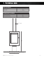
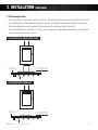
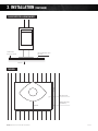
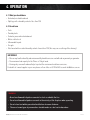
PHAROS:
MODEL SPECIFICATIONS
1. TECHNICAL DATA
2
2. PRE-INSTALLATION
3
3. INSTALLATION
5
4. OPERATION
9
5. TESTING
Keep for future use
10
1. TECHNICAL DATA
WEIGHT AND DIMENSIONS:
Dimensions Firebox
Firebox weight
Flue kit
W531 x H1250 x D530mm
167kg
Standard 7”/9”/11”
DETERMINED UNDER TEST CONDITIONS:
Nominal thermal output
Efficiency (Australian Test)
Emissions (Australian Test)
9kW
60%
1.2g/kg
1250
7 / 9” FLUE
531
OBLICA | PHAROS INSTALLATION AND USER MANUAL
PAGE 2
2. PRE-INSTALLATION
Congratulations on your purchase of the Pharos. This appliance should be installed and checked by a qualified
professional. Ensure you have read the operation guidelines thoroughly prior to first use. For any questions or
concerns please contact Oblica on 03 9416 0400.
The installation process is outlined below:
– Determine position of firebox and flue carefully observing the clearances described within this section
– Install the external flue
– Install the internal flue and engage the firebox
– Ensure the floor has adequate protection
CAUTION:
Using components or parts other than those provided by the manufacturer or modifying the specification of
components may result in inferior or unsafe operation. If such action is necessary, consult the manufacturer in the
first instance.
WARNING:
• The appliance and flue-system must be installed in accordance with AS/NZS 2918 and the
relevant building code or codes.
• Any modification of the appliance that has not been approved in writing by the testing authority
will be in breach of the approval granted for compliance with AS/NZS 4013.
• Once the flue has been installed and approved by a professional installer, the flue must not be
modified in any way.
OBLICA | PHAROS INSTALLATION AND USER MANUAL
PAGE 3
2. PRE-INSTALLATION (CONTINUED)
MINIMUM CLEARANCE – INTERNAL
2.1 Clearance from non-combustible surfaces
(eg masonry)
2.3 Clearance from combustible surfaces
(eg timber joist & concrete)
100mm minimum clearance is required from fully
non-combustible surfaces.
Clearances may be reduced with the application of
heat shielding to walls in accordance to the
Australian Building Code.
Non Combustible
100
Non Combustible
100
For information on heat shielding please contact our
office on 03 9416 0400 or email [email protected].
Configuration 1 – Parallel installation
Combustible
625mm
Combustible
2.2 Clearance from glass
625mm
400mm minimum clearance is required from normal
non-combustible glass.
Glass (frameless or aluminium frame)
Glass (frameless or aluminium frame)
400mm
400mm
Configuration 2 – Corner installation
Combustible
OBLICA | PHAROS INSTALLATION AND USER MANUAL
Combustible
750mm
IMPORTANT:
Frames must also be considered. Timber window
frames must be treated as combustible surfaces
(see 2.3). Aluminium frames can be treated as
non-combustible surfaces (see 2.2).
750mm
PAGE 4
3. INSTALLATION
3.1 Typical flue kit installation
Cowl (Chinaman Hat)
9” Outer Case
11” Outer Case
RUBBER
DEKTITE FLASHING
7” Active Flue
9” Outer Case
11” Outer Case
CEILING RING
7 / 9” Flue
OBLICA | PHAROS INSTALLATION AND USER MANUAL
PAGE 5
3. INSTALLATION (CONTINUED)
3.2 Installing the external flue
1. Place the connection piece inside the suspension bracket. This will join the single skin flue below the
bracket and the triple skin flue above the bracket which have different diameters.
2. Ensure the triple skin flue is installed as per Australian standards (see diagrams below).
PITCHED ROOF INSTALLATION
The top of the flue must be 400mm higher than the highest point of the roof. Alternatively, there must be a
minimum distance of 3 meters from any higher section of roof.
–> 40 cm
>
–3m
>
– 40 cm
–> 40 cm
FLAT ROOF INSTALLATION (LESS THAN 5˚ PITCH)
The top of the flue must be 1200mm above the roofline. Alternatively, there must be a minimum distance of
3 meters from any higher section of roof.
–> 120 cm
–> 120 cm
OBLICA | PHAROS INSTALLATION AND USER MANUAL
>
–3m
>
– 120 cm
PAGE 6
3. INSTALLATION (CONTINUED)
3.3 Protecting the floor
• Any combustible floor beneath a fireplace must have a floor protector that extends minimum 300mm at the front.
• If installed directly on combustible material, the floor protector must be made of a minimum 6mm thick cement sheet.
Non-combustible finishes can be applied to the floor protector (tiles, steel sheet, light concrete, etc).
• If the combustible floor is installed on concrete, you can replace the combustible material with non-combustible
material laid directly onto the concrete.
FLOOR PROTECTOR LAID ON TIMBER FLOOR
Combustible
floor (eg. timber)
Insulative board (6mm)
+ non combustible finish
Joist
FLOOR PROTECTOR LAID ON JOIST
Combustible
floor (eg. timber)
Insulative board (6mm)
+ non combustible finish
Joist
OBLICA | PHAROS INSTALLATION AND USER MANUAL
PAGE 7
3. INSTALLATION (CONTINUED)
FLOOR PROTECTOR LAID ON CONCRETE
Combustible
floor (eg. timber)
Non combustible finish
(eg.tiles)
Concrete
730mm
TOP VIEW
Floor protector
Combustible floor
(eg: Timber)
300mm
810mm
OBLICA | PHAROS INSTALLATION AND USER MANUAL
PAGE 8
4. OPERATION
4.1 What you should burn
• Untreated, air dried hardwood
• Split logs with a humidity content of less than 20%
4.2 Do not burn
•
•
•
•
•
•
•
Trash
Painted plastic
Coated or preservative treated wood
Waste or black coal
Inflammable liquids
Fire gels
Moist wood with a residual humidity content of more than 20% (this may cause soothing of the chimney).
IMPORTANT:
• Misuse may lead to unhealthy and environmentally harmful emissions and will void any warranty or guarantee.
• The maximum load capacity for the Pharos is 10kg of wood.
• Burning only seasoned hardwood helps to protect the environment and lower emissions.
For details of a wood supplier in your area please call our office on 03 9416 0400 or email [email protected].
WARNING:
• Do not use flammable liquids or aerosols to start or rekindle the fire.
• Do not use flammable liquids or aerosols in the vicinity of the fireplace when operating.
• Do not store fuel within prescribed installation clearance distances.
• The use of some types of preservative-treated woods as a fuel can be hazardous.
OBLICA | PHAROS INSTALLATION AND USER MANUAL
PAGE 9
5. TESTING
TEST REPORT NO HCMG/15/041
TESTING LABORATORY:
HRL Technology
MANUFACTURER:
Invicta
MODEL:
Pharos fireplace
WORK REQUESTED:
Assessment of appliance to AS/NZS 4012:2014
for determination of Power Output and Efficiency
and AS/NZS 4013:2014 for Flue Gas Emission
using hardwood fuel.
ISSUE DATE:
23/07/2015
INVESTIGATING OFFICER:
Steve Marland
RESULTS:
The Pharos solid fuel burning appliance produced an
appliance particulate emissions factor of 1.2g/kg and an
average efficiency of 60% for all burn rates, using
hardwood that complies to AS/NZS 4014.1, when tested
according to joint AS/NZS 4012, AS/NZS 4013 (2014).
CONCLUSION:
The Pharos solid fuel burning appliance complies with the
requirement of a combined efficiency of not less than 55%
and a particulate emissions factor of not greater than
2.5g/kg of hardwood that complies to AS/NZS 4014.1 in
AS/NZS 4013 (2014).
OBLICA | PHAROS INSTALLATION AND USER MANUAL
PAGE 10