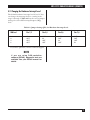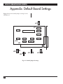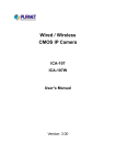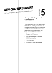
1
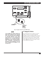
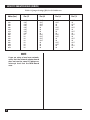
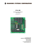
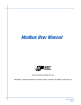
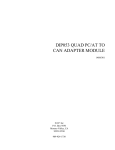
SEPTEMBER 1994
PCD61C
MPA 3270 Emulation Board (Remote)
CUSTOMER Order toll-free in the U.S. 24 hours, 7 A.M. Monday to midnight Friday: 877-877-BBOX
SUPPORT FREE technical support, 24 hours a day, 7 days a week: Call 724-746-5500 or fax 724-746-0746
INFORMATION Mail order: Black Box Corporation, 1000 Park Drive, Lawrence, PA 15055-1018
Web site: www.blackbox.com • E-mail: [email protected]
MPA 3270 EMULATION BOARD (REMOTE)
FEDERAL COMMUNICATIONS COMMISSION
RADIO FREQUENCY INTERFERENCE STATEMENT
This equipment generates, uses, and can radiate radio frequency energy and if not installed and used
properly, that is, in strict accordance with the manufacturer’s instructions, may cause interference to radio
communication. It has been tested and found to comply with the limits for a Class A computing device in
accordance with the specifications in Subpart J of Part 15 of FCC rules, which are designed to provide
reasonable protection against such interference when the equipment is operated in a commercial
environment. Operation of this equipment in a residential area is likely to cause interference, in which
case the user at his own expense will be required to take whatever measures may be necessary to correct
the interference.
Changes or modifications not expressly approved by the party responsible for compliance could void the
user’s authority to operate the equipment.
This digital apparatus does not exceed the Class A limits for radio noise emission from digital apparatus set out in the
Radio Interference Regulation of Industry Canada.
Le présent appareil numérique n’émet pas de bruits radioélectriques dépassant les limites applicables aux appareils
numériques de la classe A prescrites dans le Règlement sur le brouillage radioélectrique édicté par Industrie Canada.
TRADEMARKS
IPX™ is a trademark of Novell Incorporated.
PS/2® isa registered trademark of IBM Corporation.
MS-DOS® is a registered trademark of Microsoft Corporation.
Windows™ is a trademark of Microsoft Corporation.
Any other trademarks mentioned in this manual are acknowledged to be the property of the trademark owners.
11
MPA 3270 EMULATION BOARD (REMOTE)
Contents
Section
Page
1. Specifications ...........................................................................................................................................3
2. Introduction.............................................................................................................................................4
2.1 What to Do First..............................................................................................................................4
2.2 About This Manual.........................................................................................................................4
2.3 Compatibility With Other Products ..............................................................................................4
3. Installation ...............................................................................................................................................5
4. How to Modify the MPA 3270 Emulation Board (Remote)..................................................................6
4.1 MPA Board Settings........................................................................................................................6
4.2 Changing the I/O Address ............................................................................................................7
4.3 Changing the Hardware Interrupt Level ......................................................................................9
Appendix: Default Board Settings .............................................................................................................10
2
MPA 3270 EMULATION BOARD (REMOTE)
1. Specifications
Systems Supported — SDLC
PU Type Emulated — 2
LU Types Supported — 1 and/or 3 and 2
System Requirements — 386, 486, or Pentium PC
or PS/2® Model 30, (1) 3.5" floppy drive, PC or
MS-DOS® 3.3 or later
Interface — RS-232 DTE (external clocking only)
Connector — (1) DB25 male
Power — +5 VDC, 1.5 A from PC bus
Size — 4"W x 5"D (10.2 x 12.7 cm) half card
Weight — 2 lb. (0.9 kg)
3
MPA 3270 EMULATION BOARD (REMOTE)
2. Introduction
The MPA 3270 Emulation Board (Remote) is
a printed circuit board that provides the
communications interface between the host and
your personal computer.
• Chapter 4, How to Modify the MPA 3270
Emulation Board (Remote), describes how to
change jumpers and I/O addresses for the
Board.
Software (ordered separately) that works with
the Board features DOS and Windows™ emulation.
• Appendix, Default Board Settings, lists the
settings for the Board as shipped from the
factory.
2.1 What to Do First
Check to make sure that your package includes the
following items:
• MPA 3270 Emulation Board (Remote)
• This User’s Manual
2.2 About This Manual
This manual provides complete instructions for
installing your MPA 3270 Emulation Board
(Remote). If you have purchased additional
software (such as DOS (PCD62) or Windows
(PCD63) emulation soft- ware), or if you plan to use
another vendor’s software with the Board, refer to
the documentation that came with the software for
instructions.
We recommend that you thoroughly read this
guide before configuring or using your emulation
product.
This manual does not discuss your PC or its disk
operating system (DOS), your LAN, or specific host
application programs. If you are not familiar with
your PC, DOS, or your LAN, we recommend that
you review their documentation.
This manual contains four chapters and one
appendix:
• Chapter 1, Specifications, lists pertinent
specifications for the card.
• Chapter 2, Introduction, provides basic
information about the Board and its features.
• Chapter 3, Installation, describes in detail how
to install the Board.
4
2.3 Compatibility with Other Products
There are two situations in which your emulation
software will not run on the MPA Board:
• If there is another board installed in the PC
using the same I/O address range or hardware
interrupt level.
• If there is another software program in memory
that uses the same software interrupt level.
The MPA Board uses these hexdecimal default
settings:
• I/O base address 380 through 38F
(hexadecimal). The range is 200 through 3EF.
• Hardware interrupt level 3. The range is 2
through 5.
Your personal computer can have only one
product installed that uses these settings. You can
change the current I/O address and interrupt level
settings to avoid such conflicts with other products.
See Chapter 4, How to Modify the MPA 3270
Emulation Board (Remote), to make the hardware
changes. See your emulation software
documentation for information on making the
software changes.
Additional Files
If applicable, one or more files may be used to
check the MPA Board installation and the
configuration file parameters. These files will be
installed during the software emulation installation
process. For more details, refer to your software
emulation documentation.
MPA 3270 EMULATION BOARD (REMOTE)
3. Installation
To install the MPA 3270 Emulation Board
(Remote), follow these steps:
1. Turn all power switches off and unplug all
power cords.
2. Remove the cover from the personal computer.
3. Insert the MPA Board into one of the expansion
slots of the chassis. Secure the card with the
screw you removed before installing it.
NOTE
The MPA 3270 Emulation Board
(Remote) requires a communications
adapter cable to connect the installed
MPA Board to a modem or other
communications device. An equivalent
cable is a male/female 12-conductor
cable (wired at pins 1-8, 15, 17, 20, and
22) that conforms to the EIA RS-232C
specifications.
4. Replace the personal computer’s c over.
5. Re-connect all the cables, then connect the
modem cable.
6. Power on the PC.
5
MPA 3270 EMULATION BOARD (REMOTE)
4. How to Modify the MPA 3270
Emulation Board
(Remote)
You can install more than one communications
board in the personal computer. However, if
another communications board uses the same I/O
address or hardware interrupt level as the MPA
3270 Emulation Board (Remote), neither product
will work correctly. Follow these modification
guidelines for the MPA Board carefully. Then
change the I/O address or hardware interrupt level
in the emulation software you are using. Refer to
your emulation software documentation for
changes to I/O addresses or hardware interrupt
level settings.
4.1 MPA Board Settings
Jumper pin settings on the MPA Board define the
I/O address and interrupt level. The default base
I/O address is 380. With the default settings, your
emulation package uses I/O addresses in the
hexadecimal range 380 through 3EF. You can
change the base address to any hex multiple of 20
in the range 200 through 3E0.
The default hardware interrupt level is level 3.
You can change the interrupt level to a setting in
the range 2 through 5.
The MPA Board has several sets of jumpers.
Default settings appear in Appendix A. Only two of
these sets of jumpers are relevant:
• The pins labeled JP8 define the I/O address.
• The pins labeled JP3 define the interrupt level.
Fig. 4-1 shows the location of the jumpers for both
JP3 and JP8 on the MPA Board.
6
MPA 3270 EMULATION BOARD (REMOTE)
JP7
JP8
JP3
JP1
JP2
JP8
JP3
I/O ADDRESS
SETTING
IINTERRUPT
REQUEST
LEVEL
SETTINGS
Fig. 4-1. Jumper Locations on the MPA Board.
NOTE
If you modify the jumper settings for
either the I/O address or the interrupt
level, you must enter the new address
or Interrupt Request Level (IRQ)
specification in the configuration
program or as a runtime parameter,
depending on your emulation product.
Your emulation documentation
describes which method to use and
how to change the I/O Address or the
interrupt level.
4.2 Changing the I/O Address
You can change the base I/O address to any hex
multiple of 20 in the range 200 through 3E0.
Depending on other specialized hardware you have
installed in your PC, not all addresses in this range
will work. If you change the base address and the
software does not work properly, use another base
address. Table 4-1 lists the correct jumper settings
for each valid base I/O address.
7
MPA 3270 EMULATION BOARD (REMOTE)
Table 4-1. Jumper Settings (JP8) for I/O Addresses.
Address (hex)
Pins 1,2
Pins 3,4
Pins 5,6
Pins 7,8
200
220
240
260
280
2A0
2C0
2E0
300
320
340
360
380
3A0
3C0
3E0
OUT
OUT
OUT
OUT
OUT
OUT
OUT
OUT
IN
IN
IN
IN
IN
IN
IN
IN
OUT
OUT
OUT
OUT
IN
IN
IN
IN
OUT
OUT
OUT
OUT
IN
IN
IN
IN
OUT
OUT
IN
IN
OUT
OUT
IN
IN
OUT
OUT
IN
IN
OUT
OUT
IN
IN
OUT
IN
OUT
IN
OUT
IN
OUT
IN
OUT
IN
OUT
IN
OUT
IN
OUT
IN
NOTE
If you are using a local area network,
verify that the network adapter board
does not use the same I/O address or
interrupt level that the MPA Board
uses.
8
MPA 3270 EMULATION BOARD (REMOTE)
4.3 Changing the Hardware Interrupt Level
The default hardware interrupt level is level 3. You
can change the interrupt level to a setting in the
range 2 through 5. Table 4-2 lists the correct jumper
settings for each valid Interrupt Request (IRQ)
level.
Table 4-2. Jumper Settings (JP3) for Hardware Interrupt Level.
IRQ level
Pins 1,2
Pins 3,4
Pins 5,6
Pins 7,8
2
3
4
5
IN
OUT
OUT
OUT
OUT
IN
OUT
OUT
OUT
OUT
IN
OUT
OUT
OUT
OUT
IN
If you have questions, call for technical support.
NOTE
If you are using DOS emulation
software (PCD62), diagnostic tests are
available. See your PCD62 manual for
details.
9
MPA 3270 EMULATION BOARD (REMOTE)
Appendix: Default Board Settings
Fig. A-1 shows the default jumper settings for the
MPA Board.
JP7
JP7
JP8
JP3
JP1
JP2
JP8
JP1
JP2
JP3
Fig. A-1. Default Jumper Settings.
10
©Copyright 1994. Black Box Corporation. All rights reserved.
1000 Park Drive • Lawrence, PA 15055-1018 • 724-746-5500 • Fax 724-746-0746