1
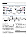
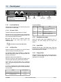
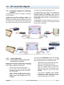
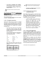
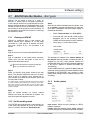
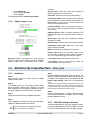
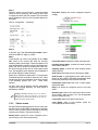
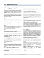
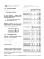
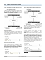
Section 1 Hardware and connections 1.1 General connection diagram 1.2 Rear panel Remote control FM base band (MPX) 1.2.1 Ethernet Streaming RS-232 USB RESET Power supply AC wires do not have to be mixed with audio wires, especially with analogical ones. Remember that all audio installation must have a trustworthy grounding. We recommend accomplishing with the standards - Article 810 of the National Electricity Code (NEC); ANSI/NFPA Nº 70-1984 in USA; IRAM 2379 and 2281-3 in Argentina. This standard provides information and guidelines for a consistent grounding. Audio inputs and outputs Analog inputs and outputs are electronically balanced. The inputs are “bridging” type, with impedance greater than 10 KOhms. The connectors used, as is standard, are female XLR-3 for the inputs and male for the outputs. SOLIDYNE Balanced analogue inputs AES-3 output 110/220 AC selector Balanced analogue outputs Take specially care with the phase. Always CHECK the correct position of the VOLTAGE SELECTOR (200/240V o 100/130V, according to the country) 1.2.2 AES-3 input Use one pair shielded audio cables of good quality, preferably with double shielding. The maximum length recommended is 30 mts, although in special cases it's possible to achieve 100 mts. accepting a little loss at high frequencies. The connection of this cables are made as is standard. See the following table: Balanced input/output connections: 1 = GND 2 = balanced positive phase (+) 3 = balanced negative phase (-) Unbalanced connections: Inputs: Signal = 2; GND = join 1 y 3 Outputs: Signal to pin 2; leave pin-3 unconnected. GND = pin 1 ADA102 CODER/DECODER Page 7