1
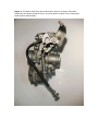
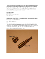
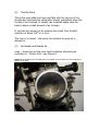
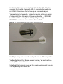
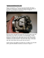
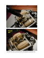
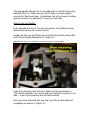
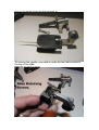
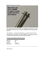
KLX 300 Maintenance Guides from www.klxzone.co.uk
Date: March 2003
Guide 9 : Changing the Jets in a Mikuni TM33-8012 Carb
Important: Please read carefully
This guide is not intended to replace the User’s Manual – rather it
is a pictorial guide to carrying out maintenance on the KLX300 and
does not necessarily represent the Kawasaki approved methods.
You should therefore realise that you use this guide at your own
risk and neither www.klxzone.co.uk or the author will accept any
responsibility for damage or injury caused as a direct or indirect
result of using this guide.
You use it at your own risk.
There being no Haynes or equivalent manual available for the
KLX300 and the official workshop manual costing around £60 I
thought it may be useful for others to use if they have not carried
out such tasks on their bike before.
This may seem a bit like a “dummys guide” as I have taken
pictures at almost every point. If you find it too tedious then
simply skip past the easy or obvious bits. I wanted to make it as
foolproof as possible and a picture is worth a thousand words.
Tony Saunders
Information
One of the modifications you can make to the KLX300R / 250R is
the replacement of the standard CV carburettor with a slide or
“pumper” carb such as the Mikuni TM33-8012.
This carburettor is a popular modification because it provides an
instant power increase and rids the bike of the annoying “lag”
between twisting the throttle and the build of the vacuum required
to lift the slide.
For UK riders it also means an end to the dreaded “carb icing”
problem that plagues the KLX when the temperature drops below
about 5 degrees and the air is slightly damp. (In the UK this
means most of the time between the end of October and the end
of March!
The replacement of the Carburettor on the KLX is covered in a
separate article. This one is aimed at the alteration of the jets and
needle in the Mikuni TM33-8012 prior to putting it on.
It is not a definitive guide – but should serve useful for those of
you, like me that don’t do this sort of thing very often ☺
Any mechanics out there that have any suggestions regarding my
methods, please let me know.
Useful Internet Web Links:
http://www.mikunioz.com/tm33.htm
http://www.lafishmag.com/CarbTuning.html
http://faq.f650.com/FAQs/CarbMiscFAQ.htm
Figure 1: The Mikuni TM33-8012 33mm Carburettor. Note the “pumper” mechanism
actuated by the throttle during the first ¼ turn that delivers a squirt of fuel, boosting the
initial response tremendously.
Jetting
Jetting is a complex subject and there are far more capable people
than myself to cover it’s intricacies. Altitude / climate and the
engine parameters will all have a profound effect on the ideal
jetting for the carb.
So here, I am working from a set of popular “base” settings and
am concentrating on how the jets and needle are altered or
replaced.
I will however cover the basics of the theory of carburetion so that
you can get some idea of which bit does what and when it comes
into play.
What is a Jet? – it’s simply a metal “screw” (usually brass) with a
hole or holes through it which fuel can pass. The bigger the hole –
the more fuel can pass – simple as that.
Carburetion Basics
A carburettor at it’s simplest is a device that regulates and delivers
an optimum mix of fuel and air to your engine so that combustion
can take place to drive the piston through it’s cycle. Whether the
bike is a 2-stroke or 4-stroke, the principle is pretty much the
same.
However in order for this to work, the carburettor has to be able
to deliver different mixtures and quantities of fuel/air at different
times depending on how hard the engine is having to work and
also the temperature at which it is operating.
At sea level the air is rich in oxygen – whereas at 14,000 in the
Rocky Mountains – the air is considerably less rich in oxygen.
Altitude therefore plays a key role in the carburettor settings
required to deliver optimum fuel and air.
Too much fuel means that the engine is running RICH. Too much
air means that the engine is running LEAN.
There are several things that govern the flow of this mixture. Most
motorcyle engines are governed, not by the speed you are doing,
but by the throttle position. The carburettor therefore has to
deliver appropriate amounts across the full range of the throttle
and it does this using four basic means:
Pilot Jet Circuit
Throttle Valve
Needle Jet and Jet Needle
The Main Jet
Additionally – the CHOKE is provided to help the carburettor when
the engine is cold and damp.
(1)
Pilot Jet Circuit
The Pilot Circuit has two components – the Pilot Jet and the Pilot
Air Screw. The Pilot Jet from the Mikuni TM33 is shown in Figure 2
– the right hand longer jet. The one the left is the Main Jet.
Figure 2: Main Jet and Pilot Jet from the Mikuni TM33
Jets have their size in the form of a number imprinted on them
(either on the side or the top).
The Pilot Jet is primarily responsible for fuel/air delivery at low
throttle openings (usually about zero to ¼ turn)
It is also likely to the jet that is affected by carb icing causing the
bike to splutter and stall at low revs or when slowing down to
stop.
The Pilot jet works in conjunction with a Pilot Air Screw that allows
a quantity of air to mix with this fuel. The Pilot Air Screw on the
Mikuni is shown in Figure 3
Figure 3: The Mikuni Pilot Mixture Screw (Highlighted). This is viewing the carburettor from
the bottom. This can be adjusted when the carb is installed on the bike.
This screw can be adjusted in or out with a flat bladed fine
screwdriver.
If you turn it OUT – it RICHENS the mixture because it restricts
the amount of air entering the pilot circuit. If turned IN it LEANS
the mixture buy increasing the amount of air entering the pilot
circuit. (try it to see!)
(2)
Throttle Valve
This is the main slide that rises and falls with the turning of the
throttle and obstructs the carburettor almost completely when the
throttle is not touched. It usually has a slanted space near the
base to allow a small amount of air through.
It controls the amount of air entering the circuit from throttle
positions of about 1/8th to ¼ turn.
The more it is raised – the leaner the mixture as more air is
allowed in.
(3)
Jet Needle and Needle Jet
mmn – these two are the ones that sometimes obviously get
confusing ☺ - Picture first – see Figure 4.
Figure 4: Jet Needle on the Throttle slide. The Needle Jet is the hole it goes through at the
bottom of the carb.
The Jet Needle is tapered and attached to the throttle slide. As
you twist the throttle, the needle lifts. It runs into the needle jet.
As it lifts it allows more fuel to flow up as the needle tapers.
The needle can be lowered or raised by moving a clip on a series
of ridges at it’s top. By raising it (lowering the clip) , it RICHENS
the mixture. By Lowering the needle (raising the clip) – it
WEAKENS the mixture – thus making it more LEAN.
Figure 5: The TM33 Jet Needle with zoom showing the five position clip
The Clip is easily removed and re-clipped on in a different position.
The Needle Jet and Jet Needle govern the fuel / air mixture from
about 1/8th to ¾ throttle turn.
Virtually all this tuning is done via the needle position with the clip
– not by altering the needle jet.
(4)
Main Jet
This is the one most people have heard of – but actually it only
governs fuel / air for about the last 3/4 to full throttle – in other
words the last quarter turn.
It is a simply brass screw with a hole through the middle and sits
at the base of the carb inside the float bowl that holds the fuel
reserve. See Figure 2 to see the main jet.
The Main jet (like the Pilot jet) is numbered according to the size –
the bigger the number the bigger the hole – therefore the more
fuel that can flow through it – and therefore the RICHER the
mixture.
So a smaller jet means LEANER running
The larger jet means RICHER running.
Chart 1: Which circuit is delivering at any one time is shown in the following chart. Note that
they overlap quite considerably.
Changing the MAIN & PILOT JETS
Using a screwdriver or allen key (my second-hand carb had a
mixture of screw types – remove the float bowl from the base of
the carb by removing the 4 screws as shown in Figure 6
Figure 6 – showing the float bowl retaining screws.
Once you have removed the float bowl you will be able to see the
float (which you need to be careful of not damaging). A valve
allows fuel to flow into the carb bowl form the fuel tank. As the
bowl fills – the float rises until it shuts off the valve. It therefore
mediates the amount of fuel in the carburettor bowl in the same
way your toilet cistern fills up each time you flush it.
Smack band in the middle is the Main Jet. It needs to be removed
with a good flat-bladed screwdriver as shown in Figure 7.
Figure 7: The Main Jet removal.
Take it off and remove the plastic collar too.
Figure 8: The Pilot Jet visible now the collar has been removed.
The Pilot Jet can be removed with a flat bladed screwdriver too.
The appropriate jets can be re-screwed back in and the float bowl
fastened back on. Make sure you don’t trap the rubber gasket
around the float bowl base. I sometimes rub a thin smear of silicon
grease around it (or Vaseline!) to ensure a nice seal.
Altering the Jet Needle.
First removed the top of the carb secured by two Phillips screws.
Nothing will spring out so don’t worry.
Inside you can see the lifting cam that lifts the throttle valve slide
and the jet needle attached to it. (Figure 9)
Figure 9: The open top of the carb showing the cam and it’s retaining bolt
Undo the retaining bolts with your 8mm socket and remove it.
The throttle actuator can now be slid out (watch the spring on the
side – it won’t go anywhere but will flick around)
Once you have removed this you can now lift the carb slide out
completely as shown in Figure 10.
Figure 10: The Actuator and the Carb Slide and Needle Jet.
To remove the needle- you need to undo the two allen screws in
the top of the slide:
Figure 11: The screws to remove
Figure 12: The Needle Clip adjustment.
The clip is easily removed using your fingers by pressing it on the
table lightly to push it off. It can be re-applied into the appropriate
groove.
Once altered – reverse the procedure you used to get it out. Reassemble the carburettor. Nothing it difficult – although the spring
is a little tricky to clip back on the throttle actuator.
Recommended BASE KLX300R Settings
Main jet
Pilot jet
Needle
Fuel screw
142.5
45
3rd clip
1 turn out
--------------------------------------------------------------------------------Job’s a fish!