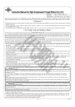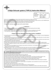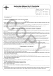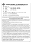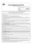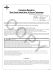
1
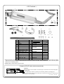
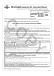
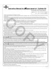
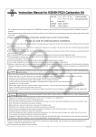
Instruction Manual for SILENT BOMBER AF
CO
Item No. :04―02―274
Fitting models and frame Nos:
AddressV125 : CF46A-100000 ∼
※excluding CF4EA-
・Thank you for purchasing one of our TAKEGAWA's products. Please strictly follow the following instructions in installing and using the products.
・Before installing the products, please be sure to check the product contents. Should you have any questions about the products, please contact your local
motorcycle dealer.
◎ Please note that, in some cases, the illustrations and photos may vary from the actual hardware.
Read all instructions first before starting the installation
◎ We do not take any responsibility for any accident or damage whatsoever arising from the use of the kit not in conformity with the instructions in the manual.
◎ We shall be held free from any kind of warranty whatsoever of products other than this product if the glitch takes place on the other products than this
one after the installation and use of this product.
◎ You are kindly requested not to contact us about the combination of our products with other manufacturers'.
◎Please note that this product is designed for exclusive use in the above-mentioned fitting models and frame numbers only and that it cannot be mounted
on any other models.
◎ For the correct installation of this product, please refer to a Suzuki’s genuine parts service manual for your vehicle.
◎ Please do installation with right tools and with great care following the installation instructions. We advise those who are technically inexperienced or without right tools to ask a technically-trustworthy specialist shop to do the work.
PY
◎ Bolts and packing will be reused. However, be sure to replace worn-down or severely-damaged ones with new ones.
◎ In the case of a stock bike, be sure to change weight rollers to the provided ones in order to ensure maximum performance of this product.
◎Do not remove the blind plug on the exhaust pipe except when you install an extra-cost AF meter (Item No.: 07-04-0032). Additionally, do not ride the bike with the blind plug detached, which causes engine troubles.
CAUTION
The following show the envisioned possibility of injuries to human bodies and property damage as a result of disregarding the
following cautions.
・Always try to drive your motorcycle at a legal speed, abiding by the laws.
・Work only when the engine and muffler are cool. (Otherwise, you will get burned.)
・Do the installation with right tools. (Otherwise, breakage of parts or injuries to you may take place.)
・Always use a torque wrench to screw bolts and nuts tight and securely to the specified torque.
(Otherwise, these parts may get damaged or fall off, resulting in accidents.)
・As some products and frames have sharp edges or protruding portions, please work with your hands protected.
(Otherwise, you will suffer injuries.)
・Before riding, always check every hardware for slack in parts like screws. If you find slack ones, screw them securely up to the specified torque.
(Otherwise, improper tightening may cause parts to come off.)
・Check those parts, to be reused such as bolts and packing, for wear or damage. If you find worn or damaged parts, replace them with new ones.
WARNING
The following show the envisioned possibility of human death or serious injuries to human bodies as a result of disregarding the
following warnings.
・Always start the engine in a well-ventilated place, and do not turn on the engine in an airtight place.
(Otherwise, you will suffer from carbon monoxide poisoning.)
・When you notice something abnormal with your motorcycle while riding, immediately stop riding and park your motorcyle in a safe place to check what has gone wrong. (Otherwise, the abnormality could lead to accidents.)
・Before doing work, make sure your motorcycle is secure on level ground for safety's sake.
(Otherwise, your motorcycle could overturn and injure you while you are working.)
・Check or carry out maintenance of your motorcycle correctly according to the procedures in the instruction manual or service manual.
(Improper checking or maintenance could lead to accidents.)
・If you find damaged parts when checking and performing maintenance of your motorcycle, do not use these parts any longer, and replace them with new ones. (The continued use of these damaged parts as they are could lead to accidents.)
・Keep plastic bags for packing the products out of infants' reach, or discard the bags. (If infants get a bag on, there is a risk of their suffocating.)
◎ Please be informed that, mainly because of improvement in performance, design changes, and cost increase, the product specifications and prices
are subject to change without prior notice.
◎ This manual should be retained for future reference.
-1-
Oct./14/’
09
∼ Kit Contents ∼
1
CO
7
8
4
2
3
6
No.
1
2
3
4
5
6
7
8
9
10
11
12
13
14
9
10
5
PY
Part Name
Muffler COMP.
Stay
Rubber
Collar
Clamp band
Band rubber
Blind plug
Sealing washer, M18
Weight roller, 12 g
Exhaust gasket
Flange bolt, M8 x 20
Flange bolt, M6 x 25
Flange nut, M8
Flange nut, M6
11
Qty
1
1
2
1
1
1
1
1
6
1
3
1
1
1
Repair Part Item No.
12
13
14
In units of
91122-33G-T00
00-00-0099
00-00-0217
00-04-0005
07-04-0023
02-00-0005
00-01-0063
00-00-0211
00-00-0115
00-00-0275
00-00-0173
1
4
4
1
1
1
1
3
2
4
4
6
6
※Please note that in ordering repair parts, be sure to quote the Repair Part Item No. Otherwise, we may not be able to accept your orders.
There are some parts, however, for which we are not in a position to accept your order in just the quantity to be used. In this case, please
take them in the quantity packed.
※ Rubber (No.3) comes with one piece of spare.
Compact LCD A/F meter (extra-cost products)
Features
With the help of a sensor installed in the exhaust pipe, the real-time air-fuel ratio is displayed in
a digital format.
As a supplementary means, this meter can be used as a guideline for managing fuel.
As you can see the change in the air-fuel ratio in real time, this will help you notice the lean
combustion at an early stage.
07―04―0032
-2-
Oct./14/’
09
∼ Installation Instructions ∼
3.Wind a band rubber around a silencer band, and attach a clamp band
to the silencer on the muffler COMP.
∼ Change of Muffler ∼
●Removal of Genuine Muffler:
1.Remove two exhaust pipe nuts connecting a cylinder and exhaust joint.
CO
4.Attach the silencer band to the stay with an 8x20 flange bolt and M8 flange nut, sandwiching the stay.
Exhaust pipe nuts
2.Remove two muffler clamp bolts which are mounting the genuine
muffler on the engine, and remove the muffler.
3.Remove an old exhaust gasket in exhaust port.
Exhaust gasket
● Installation of Stay
PY
5.
Fit a 6x25 flange bolt into the collar attached to the stay, and install for now the exhaust pipe on the muffler COMP. with an M6 flange nut.
1.Fix a cushion rubbuer to the stay, and a collar to the cushion rubber.
2.Mount the stay loosely for now with an M8x20 flange bolt.
6.Tighten the exhaust pipe nut to the specified torque.
Torque: 23 N・m (2.3 kgf・m)
7.Fully tighten the 8x20 flange bolt on the just-loosely-fastened stay to the
specified torque of:
●Installation of Bomber Muffler
1.Install a provided exhaust gasket into the exhaust port.
2.Align an exhaust pipe flange with a stud bolt on the cylinder head, and
tighten it with an exhaust pipe nut for the moment.
Torque: 23 N・m (2.3 kgf・m)
8.Fully tighten the 8x20 flange bolt on the just-loosely-fastened silencer band to the specified torque of:
Torque: 23 N・m (2.3 kgf・m)
9.Fully tighten the just-loosely-fastened 6x25 flange bolt to the specified
torque of:
Torque: 10 N・m (1.0 kgf・m)
10.After installation of these parts, check the hardware for exhaust leaks.
11.As for a bike with a stock engine, please change weight rollers referring to the installation instructions in the attached sheet.
※If the rubber become hardened with the heat, replace it / them with the repair part.
-3-
Oct./14/’
09
☆The weight rollers of our recommendation for use with this 5.With a special tool, unscrew a fixed drive face nut.
muffler are 6 pieces of 12 g weight rollers provided in this Kit. Torque: 50 N・m (5.0 kgf・m)
Fixed drive face nut
Furthermore, the suitable weight of weight rollers varies
according to the use of your motorcycle. So, arrange the weight
rollers to match how you are going to ride your motorcycle.
CO
∼ Change of Weight Rollers ∼
1.Unfasten a tapping screw to remove a belt-cooling duct cover.
Belt-cooling
duct cover
2.Remove a kick-starter lever.
Torque: 13 N・m (1.3 kgf・m)
Unscrew a clutch outer bolt to remove a clutch outer cover.
Torque: 8N・m (0.8 kgf・m)
Kickstarter
lever
Clutch outer
cover
3.Unscrew a clutch cover bolt to remove a clutch cover.
Torque: 10 N・m (1.0 kgf・m)
Special tool
< Special tool > Universal holder: 00-01-1002
6.Remove a spacer and movable drive face, and change the stock
weight rollers with the supplied weight rollers of 12 g.
Movable drive face
PY
Spacer
(Install supplied six weight rollers.)
※ Be careful that no oil or grease will stain the movable drive face or spacer. Be sure to degrease the face or spacer whenever stained with
oil or grease.
7.Install back the removed hardware in the reverse order of removal.
※ Be sure to follow the specified torque at each paragraph, and do the installation work correctly.
Clutch cover
4.Remove a gasket and dowel pins.
Gasket
Dowel pin
Co.,Ltd.
3-5-16 Nishikiorihigashi Tondabayashi Osaka Japan
TEL : 81-721-25-1357 FAX : 81-721-24-5059
URL : http://www.takegawa.co.jp
Dowel pin
-4-
Oct./14/’
09