1
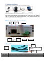
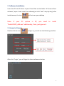
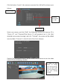
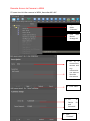
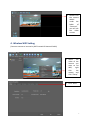
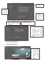
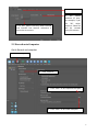
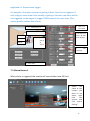
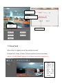
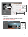
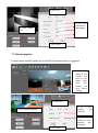
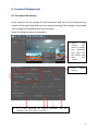
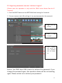
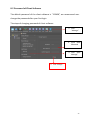
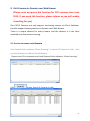
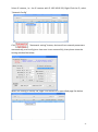
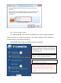
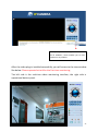
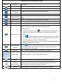
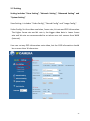
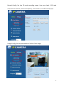
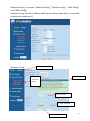
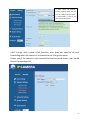
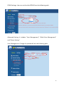
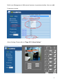
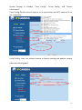
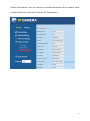
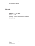
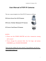
Updated on 20 August, 2013
User Manual of P2P IP Cameras
This user manual applies to all the P2P IP Cameras as follows
IPA Series: Home Pan-tilt IP Cameras
IPB Series: Outdoor Waterproof IP Cameras
IPC Series: Fixed Dome IP Cameras
NOTICE:
1. Please use the POWER ADAPTER and other accessories coming
with camera!
2. Please change the password after the first login, and please
REMEMBER your CHANGED PASSWORD!
Thank you for reading this user manual, if any problems you find out,
please kindly inform us!
1
Table of Content
1. Hardware Installation .................................................................................. 3
2. Software Installation ................................................................................... 3
3. Access to Camera ......................................................................................... 4
4. Wireless WIFI Setting ................................................................................... 7
5. Record and snapshot ................................................................................... 8
5.1 Record onto SD Card ............................................................................... 8
5.2 Record onto Computer ........................................................................... 9
6. Playback Video .......................................................................................... 11
6.1 Playback Video Recorded onto Local Computer .................................... 11
6.2 Remote Playback Video Recorded onto SD Card ................................... 11
7. Alarm Setting ............................................................................................. 12
7.1 Alarm Introduction ............................................................................... 12
7.2 Alarm I/O Description: .......................................................................... 12
7.3 Motion Detection Description .............................................................. 13
7.4 Alarm Record: ....................................................................................... 14
7.5 Alarm Email .......................................................................................... 15
7.6 Alarm FTP ............................................................................................. 16
7.7 Alarm Snapshot .................................................................................... 17
8. Password Management ............................................................................. 18
8.1 Password of Camera ............................................................................. 18
8.2 Password of Client Software ................................................................. 20
9. Visit Camera via Domain over Web Brower .............................................. 21
9.1 Access to camera via Domain ............................................................... 21
9.2 Setting .................................................................................................. 26
10. Visit Camera over Smart Phone .............................................................. 34
2
1. Hardware Installation
Please connect camera to internet like the following way
Power for camera, and connect it to router.
Note: Please check whether the working status of “Power Light” and “Network
Light” is same with the following description, if not, please reconnect the
power adaptor and network cable again.
IPA Series Camera Interface Introduction:
Power
Light
Audio
Output
Network
Light
Ethernet
Port
SD Card
Slot
Antenna
I/O Port
Power Supply
IPB and IPC Series Camera Interface Introduction:
RS485
Port
Ethernet
Audio
Port
In,
connected
external
microphone
Power
Supply
Definition
Description
Power Indicator
Orange color, it is always on when device is powered and network cable is connected correctly
Data Indicator
Green color, it is blinking when data is transmitting
3
2. Software Installation
Insert the CD into CD driver of your PC and find out the folder “IP Camera Client
software”, open it and install the software(just click “next” step by step), after
install success, the icon
Note:
If
your
PC
will arise on your desktop
system
is
XP,
you
need
to
install
“NetFx20SP2_x86.exe” additionally, if not, just ignore it.
3. Access to Camera
Double click the icon
to login in; you will see the following interface
After click “Login”, you will login the client software as below
4
Click the button “search”, the cameras connected into LAN will be shown up as
follows
“Search“button
Cameras
connected
In LAN
“Add“button
Select one camera, and click “Add”, the following interface will pop-up, fill in
“Device ID” and “Password”(the device ID and password are in the label
attached onto camera housing), and click “Finished”, the camera will be added
into the folder “Cameras” in the left side of the client software
Double Click the added camera, you will access to the camera to see the video
success like the following interface
In order to avoid
others to change
your viewing setting,
you can click “Lock”
to set a password to
lock your viewing
window
5
Remote Access to Camera in WAN
If I want to visit the camera in WAN, how should I do?
1. Right Click
folder
“Cameras”
2. Click “Add
Device
through ID”
3. Fill in a
name of the
camera and
any
information
you want to
describe
the camera
4. Click “Next”
5. Fill
in
Device ID
and
Password
6
6. Click
“Finished”
7. Double click
the camera
added
under the
folder
of
“Cameras”,
you will see
the video
success
4. Wireless WIFI Setting
(Connect camera to internet by WIFI instead of Network Cable)
1. Select
the
video of the
camera you
want to set
WIFI,
right
click
the
mouse, and
click “Setup”
2. Click “WIFI”
7
3. Check “WIFI
Switch”
5. Select one
and input
the WIFI
password
4. Click
“Search”, the
WIFI signals
will
be
shown up
6. Click “Connect”, after about
10S, the WIFI will be
connected
7. Click “Apply” and “OK”
8.
In order
to check
whether the WIFI setting
success or not, we
recommend you check
the WIFI Status at last,
“Connected”
means
setting success, “Not
Connected” means setting
failure.
5. Record and snapshot
5.1 Record onto SD Card
1. Select the video
of the camera
you want to
record
video
onto SD card,
then right click
mouse,
and
then
click
“Setup”
8
2. Click “Record”
3. Set “ON”, please note only when valid SD
card inserted into camera, otherwise it
cannot be set success
4.
Set
record
duration of time,
for example, if you
set “30”, which
means a video file
will be created
every 30 minutes
5.2 Record onto Computer
Quick Record and snapshot
1.1 Click “Mange”
2. Click “General”
3. Click “Save” to set snapshot save path
4. Click “Save” to set video save path
9
Alarm, Listen-in, Talk Back Button
When alarm is triggered, the “Alarm” button will
become RED.
Click “Listen-in” button, user can listen-in the
surrounding of the camera.
When a speaker connected to the camera, people
around the camera and computer can talk with each
other.
Click this button to
take snapshot
Click this button to start
recording video
Schedule Record
1. Click “Manage”
4. Select Camera
2.
Click
Manage”
5. Set the schedule of recording, red square means the
camera will record video at this selected time
“Record
3. Click
“Schedule
Record”
6. Click “Save” to save the schedule
7. Click “Change” to
set video save path
8. Click “Setting” to set record duration of time, for example, if you
set 20, which means a video file will be created every 20 minutes
10
6. Playback Video
6.1 Playback Video Recorded onto Local Computer
2. Set start time and end time, and then click “Search”
1. Click “Manage”
1. Click “Record onto
Computer”
4. The video recorded during the selected time will be shown up,
click “Play” to playback the video
6.2 Remote Playback Video Recorded onto SD Card
1. Click “Manage”
3. Select Camera
P
4. Set start time and end time,
then click “Search”
2. Click “ Record
onto SD Card”
5. The video recorded during the selected time will be shown up, click “Download”,
after the video is downloaded completely, and click “Play” to playback the video
11
7. Alarm Setting
7.1 Alarm Introduction
Alarm Setting includes “Alarm Source” and “Alarm Strategy”.
Alarm Source means what will trigger alarm.
Alarm Strategy means how the camera will notify alarm.
Alarm Source:
Motion Detection: Alarm will be triggered when the camera detects the motion
object.
I/O Input Detection: Alarm will be triggered when the I/O Input detects
low-level voltage signal.
Alarm Strategy: (Except Alarm Email, the other strategies in the following is valid only
when SD card is available)
Alarm Email: Camera sends email (including snapshot and event) to the preset
email address when alarm is triggered.
Alarm FTP: Camera sends pictures to the preset FTP server when alarm is
triggered.
Alarm Record: Camera records video onto SD Card when alarm is triggered.
Alarm Snapshot: Camera takes snapshot and save it onto SD Card when alarm is
triggered.
7.2 Alarm I/O Description:
Click “Alarm I/O” to set I/O input detection and I/O output voltage level. When
I/O input is enabled, low-level voltage will trigger alarm. Alarm I/O output is
high-level voltage and low-level voltage optional.
2
3
4
1
12
7.3 Motion Detection Description
The Motion Detection function of our cameras is much more intelligent and
flexible. The special designed “Six Areas Linkage Control” System greatly
reduces the false alarm.
The actualizing form of Motion Detection consists of Group, Area, Sensitivity,
and Interval.
Item
Description
User can set SIX groups alarms at most
Group
User can set SIX areas for an alarm, only when SIX areas are all
triggered, the alarm will be triggered. Such is “Six Areas Linkage
Control” System. Comparing with ONE area triggered system, this
system greatly reduces the false alarm.
Note: One group supports Six areas at most; user can set 1-6
areas according to different requirement.
The sensitivity of motion detection, the smaller value is, the
higher sensitivity is. High sensitivity means alarm is triggered
easily.
The interval of time between the current area and the previous
area
The first “1” means the number of area (6 areas at most), the
second “1” means group (6 groups at most).
1-1 means the first area of the first group
Area
Sensitivity
Interval
Meaning of number
Application 1: One area trigger:
For example: When the bag is moved, the alarm is triggered.
2.
Check group 1
3. Check area 1
1. Click “on”
for switch
4. Put area 1
into Group 1
5.
Set
sensitivity
Application 2: Multi-areas trigger:
6. Click “Save”
13
Application 2: Several areas trigger:
For example: Only when a person is getting in door, the alarm is triggered. If
only a dog (or some other little animal) is getting in the door, the alarm will be
not triggered, as the dog can’t trigger THREE areas at the same time. (This
system greatly reduces false alarm)
2. Check group 1
3. Check area 1
Area 3
4. Check
area 2
&
area 3
Area2
Area 1
1. Click “on”
for switch
5. Put area 1 &
area 2 & area
3 into Group 1
6.
Set
sensitivity
7. Click “Save”
7.4 Alarm Record:
When alarm is triggered, the camera will record video onto SD Card
1. Select
the
video of the
camera you
want to set
alarm, right
click
the
mouse, and
click “Alarm
Setting”
1.
14
3. Select “On”
4. Fill in
time
recording
2. Click “Alarm
record”
5. Click “Save”
7.5 Alarm Email
When alarm is trigged, you will be notified via email
(Outlook mail, Gmail, 163mail, 126mail and Sohu mail are available)
Notice: The SMTP/IMAP function of the email should be enabled first!
1. Select
the
video of the
camera you
want to set
alarm, right
click
the
mouse, and
click “Alarm
Setting”
2.
15
3. Fill in receiver
email, 5 receiver
email address is
available
2. Click “Alarm
Email”
4. Fill in
email
sender
5. Fill in password
of sender email
6. Click “Test email” to test
email setting success or not
7. Click “Save”
7.6 Alarm FTP
Camera sends pictures to the preset FTP server when alarm is triggered.
Notice: Please build a FTP server first!
1. Select
the
video of the
camera you
want to set
alarm, right
click
the
mouse, and
click “Alarm
Setting”
2.
16
3. Click “On”
4. Fill in the
information
accordingly
2. Click “Alarm
FTP”
5. Click “Save”
7.7 Alarm Snapshot
Camera takes snapshot and save it onto SD Card when alarm is triggered.
1. Select
the
video of the
camera you
want to set
alarm, right
click
the
mouse, and
click “Alarm
Setting”
3. Click “On”
4. Fill in
quantity
snapshot
2. Click “Alarm Snapshot”
the
of
5. Fill in the
interval of time
between
two
snapshots17
6. Click “Save”
8. Password Management
8.1 Password of Camera
Every camera has an unique ID and Password, and the ID and Password are
shown on the label attached onto the camera housing. We strongly recommend
user change the password after the first login.
Steps of changing camera’s password:
1. Select
the
camera
you
want to change
the password,
then right click
the mouse, and
then
click
“Setup”
OSD Setting
2. Click
“Other
Setting”
3. Fill in “New Password” & “Confirm Password” and click
“Change”, then click “Apply” and “OK”
18
If I forget my password, how can I retrieve it again?
(Please note this operation is only valid for IPA01 series Home Pan-tile IP
Cameras)
1. Push the RESET button at the BOTTOM of the housing for 5 seconds
2. Connect camera into LAN and login it (no need password at the moment)
3. Right Click the
camera
4. Click
Camera”
“Edit
5. Click “Setup”,
the device ID
and password
will be shown
up
Notice: You ONLY have ONE chance to retrieve the password, if you
change the password again, the operation above will be not working
again. Please contact us to retrieve your password.
19
8.2 Password of Client Software
The default password of the client software is “123456”, we recommend user
change the password after your first login
The steps of changing password of client software
1. Click
“Manage”
3. Input New
Password
2. Click “User
Manage”
4. Click “Change”
20
9. Visit Camera via Domain over Web Brower
(Please note we ignore this function for P2P cameras since June
2013, if you need this function, please inform us, we will enable
it working for you)
Our P2P IP Cameras not only support monitoring camera via Client Software,
but also support viewing camera via Domain over Web Brower
There is a unique domain for every camera, and this domain is in the label
attached onto the camera housing.
9.1 Access to camera via Domain
Use Camera finder software-“IPcam Scanning” to search IP Cameras in LAN (You
can search camera in LAN via Client Software).
Please insert CD to computer and install Camera finder software-“IPcam Scanning”
Click
Button, Search IP Cameras in LAN.
21
Select IP camera, i.e.: the IP camera with IP 192.168.0.150, Right Click the IP, select
“Network Config”
Click
“Automatic setting” button, device will set network parameters
automatically, and it will give a clue once it sets successfully, then please close the
setting window like below
When the setting is already OK, Right Click Device IP to open Web page like below
22
Fill in 【User name】: Admin
Fill in【Password】: Every camera produced by us has a unique password,
please find out the original password in the label attached to the bottom of
device and the in the label onto the CD.
Click【OK】button to go to the Web interface like below
2
Please visit camera from here in IE browser, we
STRONG RECOMMEND CUSTOMER VISIT CAMERA IN
IE BROSWER, the video is more fluently than the one
in other web browsers
Please visit camera from here when you view video
in Firefox, Chrome and Safari web browser
Please visit camera from here when you view video
via web browser in smart phone
1
When you view camera for the first time in IE
browser, please double click “video plugin” and
select a save path to download and install plug-in.
The “Plug-in” is also in the CD, user can install it from
CD directly
23
When you operate ActiveX, please click “Allow
for all websites”, which enables you to view
camera on any website
After the video plug-in installed successfully, you will access to the view window
like below. Please operate ActiveX for the first time monitoring.
The left side is the real-time video monitoring interface; the right side is
operational button panel.
24
Introduction of The Operational Button
Button
Definition
Description
Pan-Tilt Control
Change the mentoring direction and area
Panoramic cruise
Rotate as horizontal 355° ,vertical 120° and go back to middle position
Horizontal
cruising
Vertical cruising
Change the mentoring direction and area horizontally
Change the mentoring direction and area vertically
Rotate Speed
Set Rotate speed, "1"means the slowest speed, "5" means the fastest
speed
Cruise Interval
Set the cruise frequency, you can select from 1 to 60s.
Horizontal Image
Turn the image from left to right or from right to left
Vertical
Turn the image from up side to down side or from down side to up side
Image
Pre-set desired monitoring location to realize fixed point monitoring
function. The device supports to set 16 desired locations.
Operation steps:
1. Click Pan-tilt control button
Preset Location
to set a diresd monitoring direction
and area ( for example: you change the direction and area to front
door)
2. Click
to define a digital to the front door, for example, you define
“1” to front door, which means you have already set the first desired
monitrong location success, it is the front door
3. Repeat the steps above to set the second desired monitoring location;
you can set 16 locations in total.
Enable Preset
Location
Snapshot
Video adjust
Listen in
Talk back
(voice talking)
Record
1. Click
.
2. Select the number, the camera will move to the direction and area
corresponded with the number
Click it to take a snapshot and set a saving path to computer
Adjust the brightness, contrast, saturation of video
listen in to the camera's surroundings from the web browser side
People around the computer and IP Camera can talk with each other
(there should be speaker connected to IP Camera)
Click it to take a record video and set a saving path to computer
25
9.2 Setting
Setting includes “View Setting”, “Network Setting”, “Advanced Setting” and
“System Setting”
View Setting: it includes “Video Config”, “Record Config” and “Image Config”.
Video Config: Set the video resolution, frame rate, bit rate and OSD information.
The Higher frame rate and bit rate is, the bigger video data is. Lower frame
rate and bit rate are recommended to set when user visit camera from WAN
(internet).
User can set any OSD information onto video, but the OSD information should
be no more than 16 characters.
1
2
3
26
Record Config: Set the SD card recording status. User can check if SD card
inserted into camera, remained capacity, record status, and SD card format.
1
2
3
Image Config: Set the parameters of color of the image
1
2
3
27
Network Setting: It includes “Network Config”, “Wireless Conig”, “UPnP Config”
and “DDNS Config”.
Network Config: Set the IP address and Http Port information (Only recommend
professional people set it)
Wireless Config:
1. Click “Settings”
2. Click
“Wireless
Config”
4. Select SSID
3. Click “Search”
5. Enter Password
28
6. Click “Connect”
7. After about 10 seconds,
remove network cable, you can
see the “WIFI Connect Status”
is “Connected”, it means the
WIFI connected success
UPnP Config: after enable UPnP function, user does not need to do port
forwarding when the camera is connected to the first-grade router.
Please note if the camera is not connected to the first-grade router, user should
do port forwarding also.
29
DDNS Settings: User can set the third DDNS from the following path.
1
2
Advanced Setting: It includes “User Management”, “Multi-Cam Management”
and “Alarm Setting”
User Management: Change the password from the following path.
1
2
30
Multi-cam Management: Add several cameras to preview window. User can add
9 cameras at most.
1
2
3
Alarm Setting: Please refer to “Page 12:7. Alarm Setting”
31
System Setting: It includes “Time Config”, “Initial Config” and “Device
Information”.
Time Config: Set the time of camera, let it synchronize with NTP sever or PC or
set it manually.
Initial Config: User can restore camera to factory setting and update camera
from the following path.
32
Device Information: User can check the related information of the camera, such
as Release Version, Device ID, Domain, SD Card Status…….
33
10. Visit Camera over Smart Phone
IOS System: Download “Oview” from “App Store”
Android System: input “play.google.com” into web browser and
search “com.oview” or copy from CD
Click
34
Click video, you will see Four arrows,
click the arrow to move the monitoring
area
Listen in
Snapshot
Talk back
Record video
35