1
User's
Manual
Model AV550G
Zirconia Oxygen Analyzer
Averaging Converter
IM 11M12D01-01E
IM 11M12D01-01E
3rd Edition
Introduction
The EXAxt Series AV550G Zirconia Oxygen Analyzer Averaging Converter is designed
for oxygen measurement at multiple points in flue ducts of industrial furnaces and can
be used to optimize the combustion process. For the AV550G system, various types of
EXAxt ZR Series detectors as well as optional accessories are available. The best
measurement can be achieved by selecting instruments appropriate to your application.
This manual provides information, such as installation, operation, inspection and
maintenance procedures, about the instruments used in the AV550G averaging converter
measurement system. Any sections concerning instruments not included in your system
may be skipped.
Before using the instruments, read any descriptions related to your instruments and
system to ensure the best performance.
Regarding the HART communication, refer to IM 11M12D01-51E. IM 11M12D01-51E
has been published as "Model EXAxt AV550G HART protocol."
Regarding the FOUNDATION Fieldbus communication, refer to IM 11M12D01-61E.
IM 11M12D01-61E has been published as "Model EXAxt AV550G Fieldbus
communication."
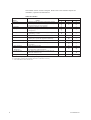
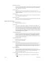
The models and description items in this manual are as follows:
Models and descriptions in this manual
Model
Product Name
Specification
Description in this manual
Installation Operation Maintenance CMPL
ZR22G
ZR22G
General-use detector
High-temperature detector (0.15m)
s
s
s
s
s
s
s
s
s
AV550G
ZO21R-L
ZO21P-H
Averaging Converter
Probe protector
High-temperature probe adapter
s
s
s
s
s
s
s
s
s
ZA8F
-
Flow setting unit (for manual calibration use)
Auxiliary ejector for high-temperature use
(Part No. E7046EC, EN)
Calibration gas unit case (Part No. E7044KF)
Check valve (Part No. K9292DN, K9292DS)
Dust filter for the detector (Part No. K9471UA)
Dust guard protector (Part No. K9471UC)
s
s
s
s
s
s
s
s
s
s
s
s
s
-
s
s
T.Int.1E
CMPL : Customer Maintenance Parts List
User's manuals of instruments related to the AV550G Averaging Converter are as
follows:
Model
Title
Manual No.
ZR22G
Separate Type Zirconia Oxygen Analyzer
IM 11M12A01-02E
ZO21DW
In-Site Type Zirconia Oxygen Analyzer
IM 11M03A02-E
Tbl-01.eps
IM 11M12D01-01E
3rd Edition: Sep. 2005 (YK)
All Rights Reserved, Copyright © 2004, Yokogawa Electric Corporation
IM 11M12D01-01E
i
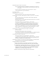
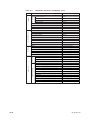
This manual consists of twelve chapters. Please refer to the reference chapters for
installation, operation and maintenance.
Table of Contents
Chapter
Outline
1. Overview
Equipment models and system configuration examples
2. Specifications
Standard specification, model code (or part number),
3. Installation
dimension drawing for each equipment
Installation method for each equipment
4. Piping
Examples of piping in three standard system
5. Wiring
configurations
Wiring procedures such as “Power supply wiring”, “output
signal wiring” or others
6. Components
7. Startup
Major parts and function are described in this manual
Basic procedure to start operation of AV550G. Chapter 7
enables you to operate the equipment immediately.
Relates to
Operation
Maintenance
s
n
s
s
s
s
s
n
s
n
s
n
n
s
s
s
n
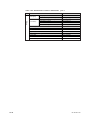
8. Detailed Data Setting
Details of key operations and displays
s
n
9. Calibration
Describes the calibration procedure required in the course
of operation.
s
n
10. Other Functions
11. Inspection and
Maintenance
Other functions described
How to conduct maintenance of AV550G and procedures
for replacement of deteriorated parts
s
n
s
s
12. Troubleshooting
This chapter describes measures to be taken when an
n
s
CMPL (parts list)
abnormal condition occurs.
User replaceable parts list
n
s
s : Read and completely understand before operating the equipment.
s : Read before operating the equipment, and refer to it whenever necessary.
n : Recommended to read it at least once.
ii
Installation
T.Int.2E
IM 11M12D01-01E
r For the safe use of this equipment
CAUTION
The cell (sensor) at the tip of the detector is made of ceramic (zirconia element). Do not
drop the detector or subject it to pressure stress.
• Do NOT allow the sensor (probe tip) to make contact with anything when installing
the detector.
• Avoid any water dropping directly on the probe (sensor) of the detector when installing it.
• Check the calibration gas piping before introducing the calibration gas to ensure that
there is no leakage of the gas. If there is any leakage of the gas, the moisture drawn
from the measured gas may damage the sensor.
• The detector (especially at the tip) becomes very hot. Be sure to handle it with gloves.
DANGER
AV550G is very heavy. Handle it with care. Be sure not to accidentally drop it. Handle
safely to avoid injury.
Connect the power supply cord only after confirming that the supply voltage matches
the rating of this equipment. In addition, confirm that the power is switched off when
connecting power supply.
Some process gas is dangerous to people. When removing this equipment from the
process line for maintenance or other reasons, protect yourself from potential poisoning
by using a protective mask or ventilating the area well.
When carrying the AV550G Averaging Converter, mark sure this is done by two or
more people.
(1) About This Manual
• This manual should be passed on to the end user.
• The contents of this manual are subject to change without prior notice.
• The contents of this manual shall not be reproduced or copied, in part or in whole,
without permission.
• This manual explains the functions contained in this product, but does not warrant that
those will suit the particular purpose of the user.
• Every effort has been made to ensure accuracy in the preparation of this manual.
However, should any errors or omissions come to the attention of the user, please
contact the nearest Yokogawa Electric representative or sales office.
• This manual does not cover the special specifications. This manual may not be
changed on any change of specification, construction and parts when the change does
not affect the functions or performance of the product.
• If the product is used in a manner not specified in this manual, the safety of this
product may be impaired.
IM 11M12D01-01E
iii
(2) Safety and Modification Precautions
• Follow the safety precautions in this manual when using the product to ensure protection and safety of personnel, product and system containing the product.
(3) The following safety symbols are used on the product as well as in this manual.
DANGER
This symbol indicates that the operator must follow the instructions laid out in this
manual in order to avoid the risk of personnel injury electric shock, or fatalities. The
manual describes what special care the operator must exercise to avoid such risks.
WARNING
This symbol indicates that the operator must refer to the instructions in this manual in
order to prevent the instrument (hardware) or software from being damaged, or a system
failure from occurring.
CAUTION
This symbol draws attention to information essential for understanding the operation and
functions.
Tip
This symbol gives information that complements the present topic.
SEE ALSO
This symbol identifies a source to which to refer.
Protective Conductor Terminal
Function Earth Terminal (Do not use this terminal as the protective conductor
terminal.)
Alternating current
iv
IM 11M12D01-01E
• Special descriptions in this manual
This manual indicates operation keys, displays and drawings on the product as follows:
• Displays on the panel 0 0.
(Ex. message display
(Ex. data display
IM 11M12D01-01E
0 BASE 0)
0 1020 )
v
r NOTICE
• Specification check
When the instrument arrives, unpack the package with care and check that the
instrument has not been damaged during transportation. In addition, please check that
the specification matches the order, and required accessories are not missing. Specifications can be checked by the model codes on the nameplate. Refer to Chapter 2
Specifications for the list of model codes.
• Details on operation parameters
When the AV550G Averaging Converter arrives at the user site, it will operate based
on the operation parameters (initial data) set before shipping from the factory.
Ensure that the initial data is suitable for the operation conditions before conducting
analysis. Where necessary, set the instrument parameters for appropriate operation.
For details of setting data, refer to chapters 7 to 10.
When user changes the operation parameter, it is recommended to note down the
changed setting data.
r After-Sales Warranty
d Do not modify the product.
d During the warranty period, for repair under warranty carry or send the product to the
local sales representative or service office. Yokogawa will replace or repair any
damaged parts and return the product to you.
d Before returning a product for repair under warranty, provide us with the model
name and serial number and a description of the problem. Any diagrams or data
explaining the problem would also be appreciated.
d If we replace the product with a new one, we won’t provide you with a repair report.
d Yokogawa warrants the product for the period stated in the pre-purchase quotation.
Yokogawa shall conduct defined warranty service based on its standard. When the
customer site is located outside of the service area, a fee for dispatching the maintenance engineer will be charged to the customer.
d In the following cases, customer will be charged repair fee regardless of warranty
period.
• Failure of components which are out of scope of warranty stated in instruction
manual.
• Failure caused by usage of software, hardware or auxiliary equipment, which
Yokogawa Electric did not supply.
• Failure due to improper or insufficient maintenance by user.
• Failure due to modification, misuse or outside-of-specifications operation which
Yokogawa does not authorize.
• Failure due to power supply (voltage, frequency) being outside specifications or
abnormal.
• Failure caused by any usage out of scope of recommended usage.
• Any damage from fire, earthquake, storms and floods, lightning, disturbances, riots,
warfare, radiation and other natural changes.
vi
IM 11M12D01-01E
d Yokogawa does not warrant conformance with the specific application at the user
site. Yokogawa will not bear direct/indirect responsibility for damage due to a specific
application.
d Yokogawa Electric will not bear responsibility when the user configures the product
into systems or resells the product.
d Maintenance service and supplying repair parts will be covered for five years after
the production ends. For repair for this product, please contact the nearest sales office
described in this instruction manual.
IM 11M12D01-01E
vii
viii
IM 11M12D01-01E
Contents
Introduction ........................................................................................................................... i
rFor the safe use of this equipment .......................................................................... iii
r NOTICE .................................................................................................................... vi
rAfter-Sales Warranty ................................................................................................ vi
1. Overview ....................................................................................................................... 1-1
1.1
System Configuration ...................................................................................... 1-1
1.1.1 System Configuration Using Flow Setting Units for Manual Calibration1-1
1.1.2 System Configuration to Perform Automatic Calibration ...................... 1-2
1.2
System Components ........................................................................................ 1-3
1.2.1 System Components and Their Applicability ......................................... 1-3
1.2.2 Detectors and Accessories ....................................................................... 1-3
2. Specifications ................................................................................................................ 2-1
2.1
General Specifications .................................................................................... 2-1
2.1.1 Standard Specifications ........................................................................... 2-1
2.2
General-use Separate-type Detector and Related Equipment ........................ 2-3
2.2.1 ZR22G General-use Separate-type Detector ........................................... 2-3
2.2.2 ZO21R-L Probe Protector ....................................................................... 2-8
2.3
High-Temperature Separate-type Detector and Related Equipment .............. 2-9
2.3.1 ZR22G (0.15m) High-Temperature Separate-type Detector .................. 2-9
2.3.2 ZO21P-H Adapter for High-Temperature Probe .................................. 2-10
2.4
AV550G Averaging Converter ..................................................................... 2-12
2.4.1 Standard Specification ........................................................................... 2-12
2.4.2 Functions ................................................................................................ 2-13
2.5
ZA8F Flow Setting Unit ............................................................................... 2-19
2.5.1 ZA8F Flow Setting Unit ........................................................................ 2-19
2.6
Other Equipment ........................................................................................... 2-21
2.6.1 Dust Filter for the Detector (Part No.: K9471UA) ............................... 2-21
2.6.2 Dust Guard Protector (Part No.: K9471UC) ......................................... 2-21
2.6.3 Auxiliary Ejector for High Temperature
(Part No. E7046EC or E7046EN) ........................................................ 2-22
2.6.4 Stop Valve (Part No. L9852CB or G7016XH) .................................... 2-24
2.6.5 Check Valve (Part No. K9292DN or K9292DS) ................................. 2-25
2.6.6 Air Set .................................................................................................... 2-26
2.6.7 Zero Gas Cylinder (Part No. G7001ZC) ............................................... 2-28
2.6.8 Cylinder Regulator Valve (Part No. G7013XF or G7014XF) ............. 2-28
2.6.9 Calibration Gas Unit Case (Part No. E7044KF) .................................. 2-29
2.6.10 Model ZR22A Heater Assembly ........................................................... 2-30
3. Installation .................................................................................................................... 3-1
3.1
viii
Installation of the Detector .............................................................................
3.1.1 Location ...................................................................................................
3.1.2 Probe Insertion Hole ................................................................................
3.1.3 Installation of the Detector ......................................................................
3.1.4 Installation of the Dust Filter( Part No K9471UA), etc .........................
3.1.5 Procedures for installing the dust guard protector (K9471UC) ..............
3.1.6 Detector with a probe protector
(Model ZO21R-L-hhh
-h *B for enhance forth ................................
3-1
3-1
3-1
3-2
3-3
3-4
3-4
IM 11M12D01-01E
3.1.7
Detector with a probe protector
(Model ZO21R-L-hhh
-h *B for dust wear protect ............................ 3-5
3.2 Installation of the Detector (Model ZR22G-015) ........................................... 3-6
3.2.1 Installation Location ................................................................................ 3-6
3.2.2 Usage of the High-temperature Probe Adapter (Model ZO21P-H) ....... 3-6
3.2.3 Probe Insertion Hole ................................................................................ 3-7
3.2.4 Mounting of the High-Temperature Detector ......................................... 3-8
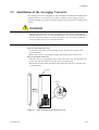
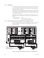
3.3 Installation of the Averaging Converter ......................................................... 3-9
3.3.1 Installation Location .............................................................................. 3-10
3.3.2 Installation in an Instrument Panel ....................................................... 3-10
3.3.3
Outdoor Installation ............................................................................. 3-12
3.4 Installation of ZA8F Flow Setting Unit ....................................................... 3-13
3.4.1 Location ................................................................................................. 3-13
3.4.2 Mounting of ZA8F Flow Setting Unit .................................................. 3-13
3.5 Installation of the Calibration Gas Unit Case .............................................. 3-15
3.5.1 Location ................................................................................................. 3-15
3.5.2 Mounting ................................................................................................ 3-15
4. Piping ............................................................................................................................. 4-1
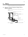
4.1
Piping for a System Using Flow Setting Units for Manual Calibration ........ 4-1
4.1.1 Parts Required for Piping in a System Using Flow Setting Units
for Manual Calibration ............................................................................ 4-3
4.1.2 Piping for the Calibration Gases ............................................................. 4-3
4.1.3 Piping for the Reference Gas .................................................................. 4-4
4.1.4 Piping to the High Temperature Probe Adapter ..................................... 4-4
4.1.5 Piping for Blowback ................................................................................ 4-6
4.1.6 Piping for Indication check ..................................................................... 4-7
4.1.7 Piping to Introduce Purge Gas When a Process Gas Alarm Occurs ...... 4-8
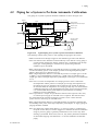
4.2 Piping for a System to Perform Automatic Calibration ................................. 4-9
4.2.1 Parts Required for Piping in a System to Perform Automatic
Calibration ............................................................................................. 4-10
4.2.2 Piping for the Calibration Gases ........................................................... 4-11
4.2.3 Piping for the Reference Gas ................................................................ 4-12
4.2.4 Piping to the High Temperature Probe Adapter ................................... 4-12
4.2.5
Piping for Blowback ............................................................................. 4-12
4.2.6
Piping for Indication Check ................................................................. 4-12
4.2.7 Piping to Introduce Purge Gas When a Process Gas Alarm Occurs .... 4-13
5. Wiring ........................................................................................................................... 5-1
5.1
General ............................................................................................................ 5-1
5.1.1 Wiring Precautions .................................................................................. 5-2
5.1.2 Wiring Holes ........................................................................................... 5-4
5.1.3 External Wiring Connection Terminals of the Averaging Converter .... 5-4
5.1.4 Types of Wiring and Cables ................................................................... 5-5
5.2 Wiring for the Averaging Converter and Peripheral Devices ........................ 5-6
5.2.1 Preparation for Wiring to the Averaging Converter ............................... 5-6
5.2.2 Preparation for Wiring to Detectors ........................................................ 5-6
5.2.3 Power and Ground Wiring ...................................................................... 5-8
5.2.4 Power Wiring to Detector Heaters .......................................................... 5-8
5.2.5 Signal Wiring to Detectors .................................................................... 5-10
5.2.6 Ground Wiring of Detectors .................................................................. 5-11
5.2.7 Wiring for Individual and Average Concentration Analog Outputs .... 5-12
IM 11M12D01-01E
ix
5.2.8
5.2.9
Wiring for Solenoid Valve for Automatic Calibration ......................... 5-12
Wiring for Individual/Common Error Contact Outputs
and Common Contact Outputs .............................................................. 5-13
5.2.10 Wiring for Contact Inputs ..................................................................... 5-15
5.3
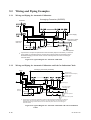
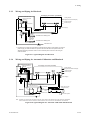
Wiring and Piping Examples ........................................................................ 5-16
5.3.1 Wiring and Piping for Automatic Calibration ...................................... 5-16
5.3.2 Wiring and Piping for Automatic Calibration and 3rd Gas Indication
Check ..................................................................................................... 5-16
5.3.3 Wiring and Piping for Blowback .......................................................... 5-17
5.3.4 Wiring and Piping for Automatic Calibration and Blowback .............. 5-17
6. Components .................................................................................................................. 6-1
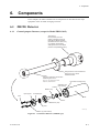
6.1
ZR22G Detector .............................................................................................. 6-1
6.1.1 General-purpose Detector (except for Model ZR22G-015) ................... 6-1
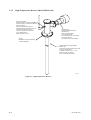
6.1.2 High-Temperature Detector (Model ZR22G-015) .................................. 6-2
6.2
AV550G Averaging Converter ....................................................................... 6-3
6.2.1 Components and Function ....................................................................... 6-3
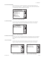
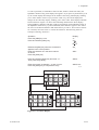
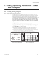
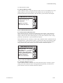
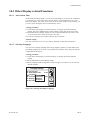
6.2.2 Touchpanel Switch Operations ............................................................... 6-3
6.2.2.1 Panels and Switches ................................................................................ 6-3
6.2.2.2 Switches and Their Functions ................................................................. 6-5
6.2.2.3 Display Configuration ............................................................................. 6-6
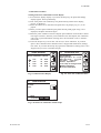
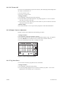
6.2.2.4 Display Functions .................................................................................... 6-7
6.2.2.5 Entering Numeric and Text Data .......................................................... 6-10
6.3
ZA8F Flow Setting Unit ............................................................................... 6-12
7. Startup ........................................................................................................................... 7-1
7.1
7.2
7.3
7.4
7.5
7.6
7.7
7.8
7.9
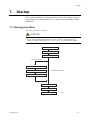
Startup procedure ............................................................................................ 7-1
Check Piping and Wiring ................................................................................ 7-2
Set Valve type ................................................................................................. 7-2
Setting Detector model ................................................................................... 7-3
Supply Power to Averaging Converter ........................................................... 7-5
Selection of Gas to be Measured .................................................................... 7-6
Current Output Range Setting ......................................................................... 7-7
Averaging Group Setting ................................................................................ 7-8
Calibration ....................................................................................................... 7-9
7.9.1 Setting Calibration Gas Concentration .................................................... 7-9
7.9.2 Performing Manual Calibration ............................................................. 7-10
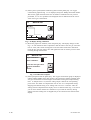
7.10 Analog Output Current Loop Check ............................................................ 7-13
7.11 Checking Operation of Contact Input, Contact Output ............................... 7-14
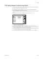
7.11.1 Contact Output Operation Check ........................................................... 7-14
7.11.2 Checking contacts used to operate solenoid valves during autocalibration7-15
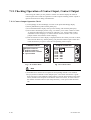
7.11.3 Checking Contact Inputs ........................................................................ 7-15
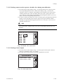
8. Setting Operating Parameters - Detail, and Examples ............................................ 8-1
8.1
Setting Analog Outputs ...................................................................................
8.1.1 Analog Output Range (Per-Channel) ......................................................
8.1.2 Output Hold Setting (Applies to All Outputs) ........................................
8.1.3 Setting Output Smoothing Coefficient
(Applies to All Analog Outputs) .............................................................
8.1.4 Setting Output Mode (Applies to All Analog Outputs) ..........................
8.2
Oxygen Concentration Alarm Setting .............................................................
8.2.1 Setting the Alarm Values (Individual Settings) ......................................
x
8-1
8-1
8-3
8-8
8-8
8-9
8-9
IM 11M12D01-01E
8.2.2 Alarm Delay Time and Hysteresis (Applies to All Alarm Settings) ...... 8-9
8.3
Assigning Contact Outputs ........................................................................... 8-13
8.4
Assigning Contact Inputs .............................................................................. 8-15
8.5
Other Settings ................................................................................................ 8-17
8.5.1 Date and Time ....................................................................................... 8-17
8.5.2 Average Value / Max. and Min. Monitoring Time .............................. 8-18
8.5.3 "Fuel" Setup: Humid Exhaust Gas or "Dry" Equivalent Oxygen
Content .................................................................................................. 8-19
8.5.4 Setting Password .................................................................................... 8-24
9. Calibration ................................................................................................................... 9-1
9.1
Calibration Briefs ............................................................................................ 9-1
9.1.1 Principle of Measurement ........................................................................ 9-1
9.1.2 Calibration Gas ........................................................................................ 9-2
9.1.3 Compensation .......................................................................................... 9-3
9.1.4 Characteristic Data from a Sensor Measured During Calibration .......... 9-4
9.2
Calibration Setup ............................................................................................. 9-5
9.2.1 Mode ........................................................................................................ 9-5
9.2.2 Calibration Setup Procedure .................................................................... 9-6
9.2.3 Zero Gas Concentration ........................................................................... 9-6
9.2.4 Span Gas Concentration .......................................................................... 9-6
9.3
Performing Calibration .................................................................................. 9-10
9.3.1 Performing Manual Calibration ............................................................. 9-10
9.3.2 Semi-Automatic Calibration .................................................................. 9-10
9.3.3 Starting AutoCalibration ........................................................................ 9-12
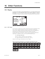
10. Other Functions ....................................................................................................... 10-1
10.1 Display ...........................................................................................................
10.1.1 Cell Voltage ..........................................................................................
10.1.2 Thermocouple Voltage ..........................................................................
10.1.3 Cold Junction Resistance (C.J. Voltage) ..............................................
10.1.4 Cell temperature ....................................................................................
10.1.5 C. J. Temperature ..................................................................................
10.1.6 Span-gas and Zero-gas Correction Ratios ............................................
10.1.7 Cell Response Time .............................................................................
10.1.8 Robustness of a Cell .............................................................................
10.1.9 Cell’s Internal Resistance .....................................................................
10.1.10 Recommended Next Calibration Date .................................................
10.1.11 Heater On-Time Ratio ..........................................................................
10.1.12 Time .....................................................................................................
10.1.13 Ch. card Rev., Ctrl. card Rev. .............................................................
10.1.14 Maximum Oxygen Concentration ........................................................
10.1.15 Minimum Oxygen Concentration ........................................................
10.1.16 Average Oxygen Concentration ...........................................................
10.1.17 History of Calibration Time .................................................................
10.1.18 Internal Temperature Alarm Logging ..................................................
10.2
Trend Graphs ...............................................................................................
10.2.1 Trend Graph Screen ..............................................................................
10.2.2 Time Axis of Trend Graph ...................................................................
10.2.3 Trend Graph Display Settings ..............................................................
10.3
Other Display-related Functions .................................................................
10.3.1 Auto-return Time ..................................................................................
IM 11M12D01-01E
10-1
10-1
10-2
10-2
10-2
10-2
10-2
10-3
10-3
10-3
10-4
10-4
10-4
10-5
10-5
10-5
10-5
10-5
10-5
10-6
10-6
10-7
10-8
10-9
10-9
xi
10.3.2 Selecting Language ............................................................................... 10-9
10.3.3 LCD Auto Off ..................................................................................... 10-10
10.3.4 Display Contrast Adjustment .............................................................. 10-10
10.3.5 Tag Name Entry .................................................................................. 10-10
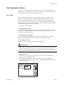
10.4 Indication Check ......................................................................................... 10-11
10.4.1 Mode .................................................................................................. 10-11
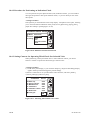
10.4.2 Procedure for Performing an Indication Check ................................ 10-12
10.4.3 Setting Contacts for Operating Third Check Gas Solenoid Valve ... 10-12
10.4.4 Setting Indication Check Timing ...................................................... 10-13
10.4.5 Running an Indication Check ............................................................ 10-15
10.4.6 Starting Auto Indication Check ......................................................... 10-18
10.5 Blowback .................................................................................................... 10-19
10.5.1 Mode .................................................................................................. 10-19
10.5.2 Setting Contacts for Operating Solenoid Valves .............................. 10-20
10.5.3 Setting Blowback Start Time ............................................................ 10-21
10.5.4 Operation of Blowback .................................................................... 10-23
10.5.5 Performing Blowback ........................................................................ 10-24
10.6
Purging ...................................................................................................... 10-25
10.7
Parameter Initialization ............................................................................. 10-27
10.8
Methods of Operating Valves in the ZA8F Flow Setting Unit ................ 10-31
10.8.1 Preparation Before Calibration .......................................................... 10-31
10.8.2 Operating the Span Gas Flow Setting Valve .................................... 10-31
10.8.3 Operating the Zero Gas Flow Setting Valve ..................................... 10-32
10.8.4 Operation After Calibration ............................................................... 10-32
11. Inspection and Maintenance .................................................................................. 11-1
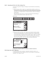
11.1 Removing and Attaching the Front Cover ................................................... 11-2
11.1.1 Removing the Front Cover .................................................................. 11-2
11.1.2 Attaching the Front Cover ................................................................... 11-2
11.2
Hot Swap Function ..................................................................................... 11-2
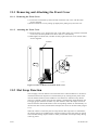
11.3
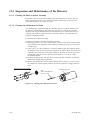
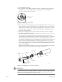
Inspection and Maintenance of the Detector .............................................. 11-4
11.3.1 Cleaning the Filter in Sensor Assembly .............................................. 11-4
11.3.2 Cleaning the Calibration Gas Tube ..................................................... 11-4
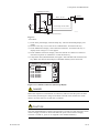
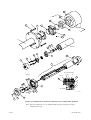
11.3.3 Replacing the Sensor Assembly .......................................................... 11-5
11.3.4 Replacement of the Heater Unit .......................................................... 11-7
11.3.5 Replacement of filter assembly ......................................................... 11-10
11.3.6 Replacement of O-ring ...................................................................... 11-10
11.3.7 Cleaning the High-temperature Probe Adapter ................................. 11-10
11.3.8 Stopping and Re-starting Operation .................................................. 11-11
11.4
Inspection and Maintenance of the Averaging Converter ....................... 11-12
11.4.1 Fuse Replacement .............................................................................. 11-12
11.4.2 Cleaning ............................................................................................. 11-13
11.5
Adding Channel Cards .............................................................................. 11-14
11.6
Adding the Expansion Power Supply Unit .............................................. 11-15
11.7
Replacing Limited Life Components ....................................................... 11-16
12. Troubleshooting ....................................................................................................... 12-1
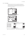
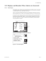
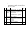
12.1 Displays and Remedies When Errors Occur ................................................ 12-1
12.1.1 Error Types .............................................................................................. 12-1
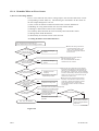
12.1.2 Operations When an Error Occurs .......................................................... 12-2
12.1.3 Error Displays ......................................................................................... 12-3
12.1.4 Remedies When an Error Occurs ........................................................... 12-4
xii
IM 11M12D01-01E
12.2
Displays and Remedies When Alarms are Generated ............................... 12-7
12.2.1
Alarm Types ....................................................................................... 12-7
12.2.2
Alarm Displays ................................................................................... 12-8
12.2.3
Remedies when Alarms are Generated .............................................. 12-9
12.3
Countermeasures When Measured Value Shows Error ........................... 12-16
12.3.1
Measured Value Higher Than True Value ....................................... 12-16
12.3.2
Measured Value Lower Than True Value ....................................... 12-17
12.3.3
Measurements Sometimes Show Abnormal Values ........................ 12-17
Customer Maintenance Parts List ................................................ CMPL 11M12D01-01E
Customer Maintenance Parts List ................................................ CMPL 11M12A01-02E
Customer Maintenance Parts List ................................................ CMPL 11M06B02-01E
Customer Maintenance Parts List ................................................ CMPL 11M03B01-10E
Customer Maintenance Parts List ................................................ CMPL 11M03B01-05E
Revision Record .................................................................................................................... i
IM 11M12D01-01E
xiii
1. Overview
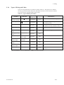
1.
Overview
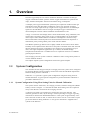
Zirconia oxygen analyzers are used in combustion facilities to measure the flue gas
oxygen concentration. Boiler operators use the oxygen measurement to optimize fuel
usage, minimize atmospheric emissions and reduce energy consumption.
A multiple point oxygen measurement system may be required for situations when gas
stratification in the flue duct affects combustion control. The AV550G Averaging
Converter can accept inputs from up to eight zirconia oxygen detectors. It sends output
signals for the individual as well as averages of multiple oxygen concentrations. A
robust multipoint converter reduces installation and maintenance costs.
A large 5.7-inch color LCD display shows various measurement, setup, calibration, and
trend screens. Its intuitive touch screen is easy to read and makes set up and maintenance simple. Other standard features include new self-diagnostics and a hot swap
function that allows a desired probe to be disconnected/reconnected for inspection or
maintenance just by turning off the power of the relevant channel.
The ZR22G separate-type detector uses a highly reliable zirconia sensor and its heater
assembly can be replaced in the field. The in situ probe is mounted on the duct wall and
directly measures the oxygen concentration of a sample gas at a temperature of up to
7008C. For higher temperature applications up to 14008C, the ZO21P-H High
Temperature Probe Protector is available for use in conjunction with a 0.15-m ZR22G
general-purpose detector.
The averaging converter system is ideal for combustion control in large utility boilers or
various industrial furnaces.
This chapter explains system configurations with some typical examples.
1.1
System Configuration
The AV550G Zirconia Oxygen Analyzer Averaging Converter system can be configured
by selecting detectors and an averaging converter that meet the individual requirements
and flow setting units for calibration.
Subsection 1.1.1 presents a typical system configuration using flow setting units for
manual calibration. A typical system configuration to perform automatic calibration is
provided in Subsection 1.1.2.
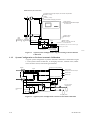
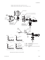
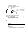
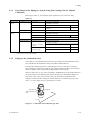
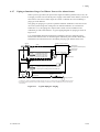
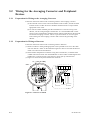
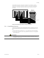
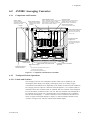
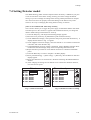
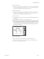
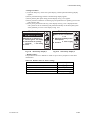
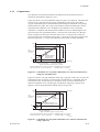
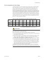
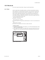
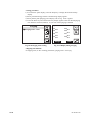
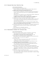
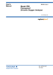
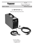
1.1.1
System Configuration Using Flow Setting Units for Manual Calibration
This system consists of detectors, an averaging converter, and flow setting units (Model
ZA8F), as shown in Figure 1.1. Note that the ZA8F Flow Setting Units are required as
many as the detectors connected to the averaging converter.
A reference gas needs to be supplied at a constant flow rate to the detectors. This
reference gas must be clean, dry air having a constant percentage of oxygen. Typically,
instrument air that has been dehumidified down to a dew point of approximately -208C
and is free from oil mist or dust, is used as the air source. This air is also used as a span
gas for the detectors during calibration. A zero gas for calibration is supplied from a
cylinder to the detectors.
IM 11M12D01-01E
1-1
ZR22G Detector (max. 8 detectors)
Cell output, thermocouple output, cold contact compensation
(0.75mm2, 6-core)
Heater
(1.25mm2, 2-core)
Model AV550G Averaging Converter
Analog outputs :
Averaged and individual outputs
4 to 20 mA DC
Contact output
Contact input
Check
Stop
Valve
Valve
L9852CB
or K9292DN
G7016XH
K9292DS
Flowmeter
Needle
Valve
Airset
Reference gas
Calibration gas
Instrument air
Power supply :
100 / 115 V AC, 230V AC
50 / 60 Hz65%
Span gas (Calibration gas unit same as for zero gas)
Calibration gas unit case
Model ZA8F
flow setting unit
Calibration gas
pressure regulator
Zero gas cylinder
F01.EPS
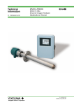
Figure 1.1 Typical System Configuration Using Flow Setting Units for Manual
Calibration
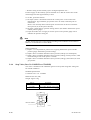
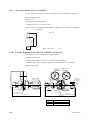
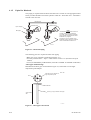
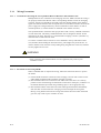
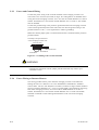
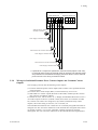
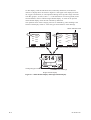
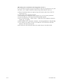
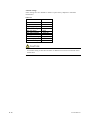
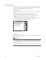
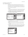
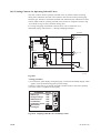
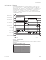
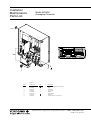
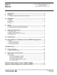
1.1.2
System Configuration to Perform Automatic Calibration
A typical system configuration to perform automatic calibration is illustrated in Figure
1.2. The system consists of detectors, an averaging converter, solenoid valves, needle
valves for flow control, and a float-type flowmeter.
Averaging Converter (AV550G)
Detector
Signal
Analog outputs:
Averaged and individual outputs
Heater
Contact output
Solenoid valve
Contact input
Calibration contact outputs
Power supply
Calibration gas line
Needle valve
Solenoid valve
Reference gas
line
Flowmeter
Stop valve
Span gas cylinder
(Instrument air)
Pressure regulator
Flowmeter
Instrument air
Air set
Needle valve
Zero gas cylinder
Figure 1.2 Typical System Configuration to Perform Automatic Calibration
1-2
IM 11M12D01-01E
1. Overview
1.2
System Components
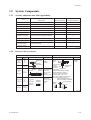
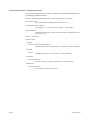
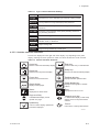
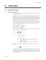
1.2.1
System Components and Their Applicability
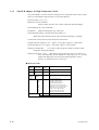
Item
Model / Part Number/
System 1
System 2
Specifications
Manual Calibration
Automatic Calibration
Averaging Converter
AV550G-h (A or B)
s
s
Detector
See §1.2.2
ssd
ssd
Flow setting unit
ZA8F
s
Needle valve
For flow control
s
Flowmeter
0 to 1 L/min
s
Solenoid valve
G700hXP, E7057Gh
s
Solenoid valve for
zero/span switching
Solenoid valve for switching two streams
s
Stop valve
L9852CB, G7016XH
s
s
Air set
K9473XH, K9473XJ, G7004XF, K9473XG
s
s
Pressure regulator for
zero gas cylinder
G7013XF, G7014XF
s
s
Zero gas cylinder
G7001ZC
s
s
Tbl 1-2.eps
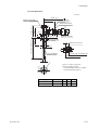
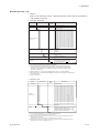
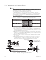
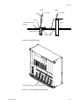
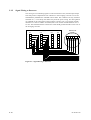
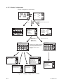
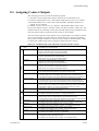
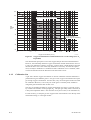
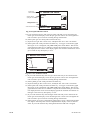
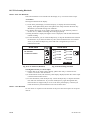
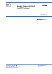
1.2.2
Detectors and Accessories
Process gas temperature 0 to 7008C
Mounting
Insertion
length
Horizontal
to
vertical
0.4
to
2m
Vertical
2.5 m
or more
Horizontal
to
vertical
3m
or less
Horizontal
to
vertical
0.4
to
2m
Vertical
2.5 m
or more
General-use Probe
Detector
(ZR22G)
Detector
(ZO21DW-L)
Process gas temperature 0 to 14008C
Boiler
Heating
furnace
Probe Protector
(ZO21R) Detector For pulverized
(ZR22G) coal boiler
Gas Flow
with gas flow
velocity
10 m/s or more
Sample inlet
Filter
(K9471UA)
or
Dust Guard
Protector
(K9471UC)
Detector
(ZR22G)
+
High temperature detector
Application
Black liquid
recovery boiler
Cement
Kiln
Sample
outlet
Application
Heating
furnace
Absorption
structure
High
Probe protector
temperature
for high
temperature use
detector
ZO21P-H
Sample inlet
Temperature:
Probe material SUS310S 8008C
Probe material SiC 14008C
Mounting: Vertical downwards
Insertion length: 1.0m, 1.5m
When duct pressure is atmospheric
or negative, attach air ejector.
High temperature auxiliary
ejector (E7046EC, E7046EN)
Pressure gauge
Needle
valve
Ejector
assy.
Inlet
Blow
F1.4E.EPS
IM 11M12D01-01E
1-3
1-4
IM 11M12D01-01E
2. Specifications
2.
Specifications
This chapter describes the specifications for the following:
ZR22G
General-use separate-type detector (See Section 2.2.1)
ZO21R-L
Probe protector (See Section 2.2.2)
ZR22G (0.15 m)
High-temperature separate-type detector (See Section 2.3.1)
ZO21P-H
Adapter for High temperature probe (See Section 2.3.2)
AV550G
Averaging converter (See Section 2.4)
ZA8F
Flow setting unit (See Section 2.5.1)
Other equipment (See Section 2.6)
2.1
General Specifications
2.1.1
Standard Specifications
Measured Object: Oxygen concentration in combustion exhaust gas and mixed gas
(excluding inflammable gases)
To check if sampled gases containing a corrosive gas such as ammonia or
chlorine may be applicable to our oxygen gas analyzer, contact with
YOKOGAWA or its agent.
Measurement System: Zirconia system
Oxygen concentration: 0.01 to 100 vol% O2
Output Signal: 4 to 20 mA DC (maximum load resistance 550V)
Measurement Range: Any setting in the range of 0 to 5 through 0 to 100 vol% O2 (in
1 vol% O2), or partial range
Digital Communication (HART): 250 to 550V, depending on number of field devices
connected to the loop (multi-drop mode).
Note: HART is a registered trademark of the HART Communication Foundation.
Display Range:
0 to 100 vol% O2
Warm-up Time:
Approx. 20 min.
Repeatability: (Excluding the case where the reference air is by natural convection)
60.5% Maximum value of range setting. (range up to 0 to 25 vol% O2)
61% Maximum value of range setting.
(range from 0 to 25 vol% O2 up to 0 to 100 vol% O2)
Linearity:
IM 11M12D01-01E
(Excluding standard gas tolerance)
2-1
(Excluding the case where the reference air flow is natural convection)
(Use oxygen of known concentration (in the measuring range) as the zero and
span calibration gas.)
61% Maximum value of range setting ; from 0 to 5 vol% O2 to 0 to 25
vol% O2 range
(Sample gas pressure: within 64.9 kPa)
63% Maximum value of range setting ; from 0 to 25 vol%O2 to 0 to 50 vol%
O2 range
(Sample gas pressure: within 60.49 kPa)
65% Maximum value of range setting ; from 0 to 50 vol% O2 to 0 to 100 vol%
O2 range (Sample gas pressure: within 60.49 kPa)
Drift: (Excluding the first two weeks in use)
(Excluding the case where the reference air flow is natural convection.)
Both zero and span 62% Maximum value of range setting/month
Response Time : Response of 90% within 5 seconds. (Measured from when gas is
introduced from calibration gas inlet and analog output start changing.)
2-2
IM 11M12D01-01E
2. Specifications
2.2
General-use Separate-type Detector and Related
Equipment
General-use separate-type detector ZR22G can be used in combination with the probe
protector ZO21R-L (see Section 2.2.2).
2.2.1
ZR22G General-use Separate-type Detector
Sample Gas Temperature: 0 to 7008C (Probe only)
It is necessary to mount the cell using Inconel cell-bolts when the temperature
is 6008C or greater.
700 to 14008C (with High Temperature Probe Adapter)
For high-temperature sample gas, apply 0.15 m length probe and High tempera
ture Probe Adapter ZO21P-H.
Sample Gas Pressure: -5 to +250 kPa (When the pressure in the furnace exceeds 3 kPa,
it is recommended that you compensate for this pressure. When the pressure in
the furnace exceeds 5 kPa, you must perform pressure compensation.)
For 0.15m probe, 0.5 to 5 kPa.
No pressure fluctuation in the furnace should be allowed.
Note: When the detector is used in conjunction with a check valve and a ZA8F
Flow Setting Unit, the maximum pressure of sample gas is 150 kPa. When with
a check valve and a ZR40H Auto Calibration Unit, it is 200 kPa. If the pressure
of your sample gas exceeds these limits, consult with Yokogawa.
Probe Length: 0.15, 0.4, 0.7, 1.0, 1.5, 2.0, 2.5, 3.0, 3.6, 4.2, 4.8, 5.4 m
Probe Material: SUS 316 (JIS)
Ambient Temperature: -20 to +1508C
Reference Air System: Natural Convection, Instrument Air, Pressure Compensation
(other than for probe length 0.15 m)
Instrument Air System (excluding Natural Convection) :
Pressure; 200 kPa + the pressure inside the furnace (It is recommended to use
air which has been dehumidified by cooling to dew point -208C or less, and had
dust or oil mist removed.)
Consumption; Approx. 1 Nl/min
Material in Contact with Gas: SUS 316 (JIS), Zirconia, SUS 304 (JIS) (flange),
Hastelloy B, (Inconel 600, 601)
Construction: Heater and thermocouple replaceable construction.
Non explosion-proof JIS C0920 / equivalent to IP44D.
Equivalent to NEMA 4X/IP66 (Achieved when the cable entry is completely
sealed with a cable gland in the recirculation pressure compensated version.)
IM 11M12D01-01E
2-3
Terminal Box Case: Material; Aluminium alloy
Terminal Box Paint Color:
Case; Off-white (Munsell 0.6GY3.1/2.0)
Cover; Moss green (Munsell 2.5Y8.4/1.2)
Finish: Polyurethane corrosion-resistant coating
Gas Connection:
Rc1/4 or 1/4FNPT
Wiring Connection: G1/2, Pg13.5, M20 by 1.5 mm, 1/2 NPT
Installation:
Flange mounting
Probe Mounting Angle:
Horizontal to vertically downward.
When the probe insertion length is 2 m or less, can install at angles from
horizontal to vertically downward.
When the probe insertion length is 2.5 or more, mount vertically downward
(within 658), and if using a probe protector install at angles between horizontal
and vertically downward (within 658).
2-4
Weight:
Insertion length of 0.4 m:
approx. 6 kg (JIS 5K 65) / approx. 11 kg (ANSI 150 4)
Insertion length of 1.0 m:
approx. 8 kg (JIS 5K 65)) / approx. 13 kg (ANSI 150 4)
Insertion length of 1.5 m:
approx. 10 kg (JIS 5K 65)) / approx. 15 kg (ANSI 150 4)
Insertion length of 2.0 m:
approx. 12 kg (JIS 5K 65)) / approx. 17 kg (ANSI 150 4)
Insertion length of 3.0 m:
approx. 15 kg (JIS 5K 65)) / approx. 20 kg (ANSI 150 4)
Insertion length of 3.6 m:
approx. 17 kg (JIS 5K 65)) / approx. 22 kg (ANSI 150 4)
Insertion length of 4.2 m:
approx. 19 kg (JIS 5K 65)) / approx. 24 kg (ANSI 150 4)
Insertion length of 4.8 m:
approx. 21 kg (JIS 5K 65)) / approx. 26 kg (ANSI 150 4)
Insertion length of 5.4 m:
approx. 23 kg (JIS 5K 65)) / approx. 28 kg (ANSI 150 4)
IM 11M12D01-01E
2. Specifications
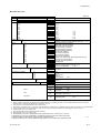
d Model and Codes
Style: S2
Option
code
Suffix code
Model
ZR22G
Separate type Zirconia Oxygen/ High Temperature Humidity Analyzer, Detector
-015
-040
-070
-100
-150
-200
-250
-300
-360
-420
-480
-540
Wetted material -S
-C
0.15 m (for high temperature use)
(*1)
0.4 m
0.7 m
1.0 m
1.5 m
2.0 m
2.5 m
(*2)
3.0 m
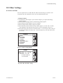
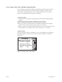
(*2)
3.6 m
(*2)
4.2 m
(*2)
4.8 m
(*2)
5.4 m
(*2)
SUS316
Stainless steel with Inconel calibration gas tube
(*11)
ANSI Class 150 2 RF SUS304
ANSI Class 150 3 RF SUS304
ANSI Class 150 4 RF SUS304
DIN PN10 DN50 A SUS304
DIN PN10 DN80 A SUS304
DIN PN10 DN100 A SUS304
JIS 5K 65 FF SUS304
JIS 10K 65 FF SUS304
JIS 10K 80 FF SUS304
JIS 10K 100 FF SUS304
JIS 5K 32 FF SUS304 (for high temperature use) (*4)
JPI Class 150 4 RF SUS304
JPI Class 150 3 RF SUS304
Westinghouse
Natural convection
External connection (Instrument air) (*12)
Pressure compensated
(*12)
Length
Flange
(*3)
Description
-A
-B
-C
-E
-F
-G
-K
-L
-M
-P
-Q
-R
-S
-W
Reference air
-C
-E
-P
Gas Thread
-R
-T
Connection box thread
Instruction manual
Rc 1/4
1/4 FNPT
-P
-G
-M
-T
-Q
G1/2
Pg13.5
M20 x1.5 mm
1/2NPT
Quick connect
Japanese
English
-J
-E
-A
(*9)
Always -A
/D
DERAKANE coating (*10)
/C
Inconel bolt
(*5)
/CV
/SV
Check valve
Stop valve
(*6)
(*6)
Filter
/F1
/F2
Dust Filter
(*7)
Dust Guard Protector (*7)
Tag plates
/SCT
/PT
Stainless steel tag plate
Printed tag plate
Options
Valves
(*8)
(*8)
*1 Used with the ZO21P High Temperature Probe Adapter. Select flange (-Q).
*2 When installing horizontally the probe whose insertion length is 2.5 meters or more, use the Probe Protector. Be sure to specify
ZO21R-L-200-h. Specify the flange suffix code either -C or -K.
*3 The thickness of the flange depends on its dimensions.
*4 Not used in conjunction with —P (pressure compensation) for reference air. The flange thickness does not conform to JIS specification
*5 Inconel probe bolts and U shape pipe are used. Use this option for high temperature use (ranging from 600 to 700 8C).
*6 Specify either /CV or /SV option code.
*7 Not used with the high temperature humidity analyzer.
*8 Specify either /SCT or /PT option code.
*9 Not waterproof, avoid rain. Operating maximum temperature is 808C. Available only in the U.S.
*10 Available only in the U.S. DERAKANE is a registered trademark of the Dow Chemical Company.
T2.1.EPS
*11 Recommended if measured gas contains corrosive gas like chlorine.
*12 Piping for reference air must be installed to supply reference air constantly at a specified flow rate.
IM 11M12D01-01E
2-5
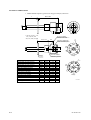
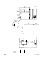
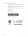
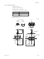
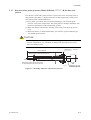
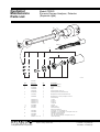
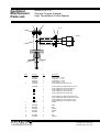
EXTERNAL DIMENSIONS
1. Model ZR22G Separate type Zirconia Oxygen Analyzer, Detectors
L
283 to 292
85
[124
[50.8
t
L=0.15, 0.4, 0.7, 1.0,
1.5, 2.0, 2.5, 3.0
3.6, 4.2, 4.8, 5.4 (m)
Rc1/4 or 1/4NPT
Reference air inlet
155 to 163
69
C
2-G1/2,2-1/2NPT etc.
Cable connection port
48
25
[A
[B
Rc1/4 or 1/4NPT
Calibration gas inlet
Flange
Flange
ANSI Class 150 2 RF SUS304
ANSI Class 150 3 RF SUS304
ANSI Class 150 4 RF SUS304
DIN PN10 DN50 A SUS304
DIN PN10 DN80 A SUS304
DIN PN10 DN100 A SUS304
JIS 5K 65 FF SUS304
JIS 10K 65 FF SUS304
JIS 10K 80 FF SUS304
JIS 10K 100 FF SUS304
JIS 5K 32 FF SUS304
JPI Class 150 4 RF SUS304
JPI Class 150 3 RF SUS304
Westinghouse
2-6
A
152.4
190.5
228.6
165
200
220
155
175
185
210
115
229
190
155
B
120.6
152.4
190.5
125
160
180
130
140
150
175
90
190.5
152.4
127
C
4 - [19
4 - [19
8 - [19
4 - [18
8 - [18
8 - [18
4 - [15
4 - [19
8 - [19
8 - [19
4 - [15
8 - [19
4 - [19
4 - [11.5
t
19
24
24
18
20
20
14
18
18
18
5
24
24
14
Flange
C
[A
[B
Flange
F2.1E.EPS
IM 11M12D01-01E
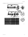
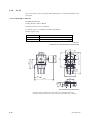
2. Specifications
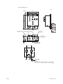
Model ZR22G...-P (with pressure compensation) Separate type Zirconia Oxygen Analyzer, Detectors
303
L
85
[124
[50.8
t
L=0.4, 0.7, 1.0, 1.5,
2.0, 2.5, 3.0, 3.6,
4.2, 4.8, 5.4 (m)
Rc1/4 or 1/4NPT
Reference air inlet
L
156
87
C
2-G1/2, 2-1/2NPT etc.
Cable connection port
t
48
25
[A
[B
Reference gas outlet
Flange
PIPING
:B
PIPING : A
Flange
ANSI Class 150 2 RF SUS304
ANSI Class 150 3 RF SUS304
ANSI Class 150 4 RF SUS304
DIN PN10 DN50 A SUS304
DIN PN10 DN80 A SUS304
DIN PN10 DN100 A SUS304
JIS 5K 65 FF SUS304
JIS 10K 65 FF SUS304
JIS 10K 80 FF SUS304
JIS 10K 100 FF SUS304
JPI Class 150 4 RF SUS304
JPI Class 150 3 RF SUS304
Westinghouse
IM 11M12D01-01E
A
152.4
190.5
228.6
165
200
220
155
175
185
210
229
190
155
B
120.6
152.4
190.5
125
160
180
130
140
150
175
190.5
152.4
127
Rc1/4 or 1/4NPT
Calibration gas inlet
Stop Valve
C
4 - [19
4 - [19
8 - [19
4 - [18
8 - [18
8 - [18
4 - [15
4 - [19
8 - [19
8 - [19
8 - [19
4 - [19
4 - [11.5
Flange
C
t
19
24
24
18
20
20
14
18
18
18
24
24
14
PIPING
A
B
B
A
B
B
A
A
B
B
B
B
A
[A
[B
Flange
F2.2E.EPS
2-7
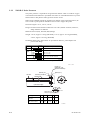
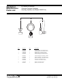
2.2.2
ZO21R-L Probe Protector
This probe protector is required for the general-use detector when it is used for oxygen
concentration measurements in powdered coal boilers or in fluidized furnaces to prevent
abrasion due to dust particles when gas flow exceeds 10 m/s.
When using a ZR22G general-use separate-type detector in the horizontal position, be
sure to select a probe protector ZO21R-L-hhh-h*B to support the probe.
Insertion Length: 1.05 m, 1.55 m, 2.05 m.
Flange: JIS 5K 65A FF SUS304. ANSI Class 150 4 FF (without serration). However,
flange thickness is different.
Material: SUS316 (JIS), SUS304 (JIS) (Flange)
Weight: 1.05 m; Approx. 6/10 kg (JIS/ANSI), 1.55 m; Approx. 9/13 kg (JIS/ANSI),
2.05 m; Approx. 12/16 kg (JIS/ANSI)
Installation: Bolts, nuts, and washers are provided for detector, probe adapter and
process-side flange.
Model
Suffix code
Option
code
Description
ZO21R -L
Probe Protector (0 to 700 8C)
Insertion
length
1.05 m (3.5 ft)
1.55 m (5.1 ft)
2.05 m (6.8 ft)
-100
-150
-200
-J
-A
Flange ( *1)
Style code
JIS 5K 65 FF SUS304
ANSI Class 150 4 FF SUS304
Style B
*B
T2.2E.EPS
*1 Thickness of flange depends on dimensions of flange.
Unit ; mm
Flange <1>
(with bolts, nuts,
gasket and washer)
Washer (12)
Mounting nut (M12)
Gas flow
gasket (t1.5)
[B
[A
[60.5
SUS316
D t
l (Insertion length)
l=1050,1550,2050
[B
C
Dimensions of
holes on opposing surface
Flange<1>
A
B
C
t
D
JIS 5K 65 FF
SUS304
155
130
4 -[15
5
40
8 -[19 12
50
ANSI Class
150 4 FF SUS304
228.6 190.5
F2.3E.EPS
2-8
IM 11M12D01-01E
2. Specifications
2.3
High-Temperature Separate-type Detector and Related
Equipment
2.3.1
ZR22G (0.15m) High-Temperature Separate-type Detector
Standard Specifications
Construction:
Water-resistant, non-explosionproof
Probe length:
0.15 m
Terminal box:
Aluminium alloy
Probe material: Probe material in contact with gas: SUS 316 (JIS) (Probe), SUS 304
(JIS) (Flange), Zirconia (Sensor), Hastelloy B, (Inconel 600, 601)
Weight:
Approx. 3 kg
Installation:
Flange mounting (The use of high-temperature detector probe adapter
ZO21P-H is necessary.)
Flange standard: JIS 5 K 32 FF equivalent (thickness varies)
Mounting angle: Any angle between horizontal and vertical (high-temperature probe is
fitted with an adapter) Reference gas and calibration gas piping
connection:Rc 1/4 or 1/4 NPT female
G 1/2, Pg 13.5, M20 3 15, 1/2 NPT
Cable inlet:
Ambient temperature: -20 to 1508C
Sample gas temperature: 0 to 7008C (temperature at the measuring point of the sampling gas. 0 to 7508C or 0 to 14008C when the probe adapter for high
temperature is used.
Temperature of the probe adapter shall not exceed 3008C to protect the
gasket and avoid the bolts seizing together.
Sample gas pressure: -0.5 to +5 kPa: when used at the range of more than 0 to
25 vol% O2, -0.5 to +0.5 kPa. (An auxiliary ejector is required for
negative pressure application.)
Model and Code
Refer to “Model and Code” in page 2-5.
External Dimensions
Refer to the Figure in page 2-6.
IM 11M12D01-01E
2-9
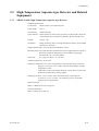
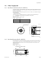
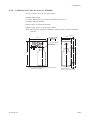
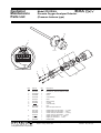
2.3.2
ZO21P-H Adapter for High-Temperature Probe
The probe adapter is used to lower the sample gas to a temperature below 7008C (below
3008C at probe adapter surface) before it is fed to the detector.
Insertion length: 1 m, 1.5 m
Material in Contact with Gas:
SUS 316 (JIS), Zirconia, SiC or SUS 310S, SUS 304(JIS) (flange)
Probe Material: SiC, SUS 310S (JIS)
Installation:
Flange mounting (FF type or RF type)
Probe Mounting Angle: Vertically downward within 658
Where the probe material is SUS 310S, horizontal mounting is available.
Construction: Non explosion-proof. Rainproof construction
Weight: Insertion length of 1.0 m: approx. 6.5 kg (JIS) / approx. 8.5 kg (ANSI)
Insertion length of 1.5 m: approx. 7.5 kg (JIS) / approx. 9.5 kg (ANSI)
Sample gas temperature:
0 to 14008C (when using SiC probe) 0 to 8008C (when
using SUS 310S probe adapter)
Sample gas pressure: -0.5 to + 5 kPa. When using in the range of 0 to 25 vol% O2 or
more, the sample gas pressure should be in the range of -0.5 to +0.5 kPa.
(Where the sample gas pressure for the high-temperature probe is
negative, an auxiliary ejector is necessary.)
d Model and Codes
Option
Description
code
ZO21P -H ....................................... High Temperature Probe Adapter
-A ..................................... SiC
Material -B ..................................... SUS 310S
Model
Insertion
length
Suffix code
-100 ............................... 1.0 m
-150 ............................... 1.5 m
Flange
Style code
-J .............................
-N ............................
-M ............................
-L ............................
-A ............................
-R ............................
-Q ............................
-T ............................
-S ............................
-E ............................
JIS 5K 50 FF SUS304
JIS 10K 65 FF SUS304
JIS 10K 80 FF SUS304
JIS 10K 100 FF SUS304
ANSI Class 150 4 RF SUS304
ANSI Class 150 2 1/2 RF SUS304
ANSI Class 150 3 RF SUS304
JPI Class 150 3 RF SUS304
JPI Class 150 4 RF SUS304
DIN PN10 DN50 A SUS304
*A ...................... Style A
T2.3E.EPS
2-10
IM 11M12D01-01E
2. Specifications
External Dimensions
Unit: mm
Approx. 351
Measured gas outlet
Flange (Thickness)
JIS 5K 32 FF
Gasket (Thickness 3)
180
fA
Flange <1>
Approx. 48
110
f124
f60.5
85
f115
f60.5
Detector (ZR22G)
Flange provided
by customer
69
Reference air inlet <2>
f52 over
42
25
170
Approx, 100
(Insertion length) (Note1)
Approx, 215
R1/2 (Note2)
Pipe hole (2-G1/2,2-1/2NPT.etc)
High temperature
Probe SiC pipe
Calibration gas inlet <3>
f30
C
(Note 1) 1=1000 or 1500 (mm)
(Note 2) Sample gas outlet
(if the sample gas pressure is negative,
connect the auxiliary ejector.)
[A
[B
<1> Flange
JIS 5K 50 FF SUS304
ANSI Class 150 4 RF SUS304
<2>,<3> joint
A
B
C
Rc 1/4
130
105
4-[15
1/4 FNPT
228.6 190.5
8-[19
F2.4E.EPS
IM 11M12D01-01E
2-11
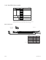
2.4
AV550G Averaging Converter
2.4.1
Standard Specification
Compatibility of Detectors : ZR22G, ZO21D, ZO21DW
Number of Detectors : 1 to 8
Expandable up to 8
Bases, these for 4CH and 8CH are available
Averaging interval : 0.2 seconds
Display: 5.7 inches color LCD display of size 320 by 240 dot with touch screen
Output Signal: 4 to 20 mA DC (maximum load resistance 550V)
Average-value Output; 3 points
Independent Output; Output to each channel
Common isolation / Individual isolation selectable
(Note) Number of averaging output is 2 when suffix code “ -F”
(FOUNDATION Fieldbus communication) is selected.
Independent Output; Output to each channel
Common isolation / Individual isolation selectable.
Used exclusively for communication when suffix code “ -F”
(FOUNDATION Fieldbus communication) is selected.
Contact Output: Contact capacity 30V DC 3A, 250V AC 3A (resistive load)
Normally open / normally closed selectable
Common Contact Output; 5 points, Four of the output points can be selected to either
normally energized or normally deenergized status.
Contact output 5 is normally energized.
Contact Output for Individual Channel Fail; Output to each channel
Normally energized.
Solenoid Valve Contact Output: Contact capacity 30V DC 1A, 250V AC 1A,
24V DC (option code "/24" ) maximum output current 50 mA
Contact Input: 2 points, voltage free contacts
Ambient Temperature: -5 to +508C
Storage Temperature: -20 to +708C
Humidity Range: 10 to 85%RH (non-condensing)
Installation Altitude: 2000 m or less
Category based on IEC 1010: II (Note)
Pollution degree based on IEC 1010:2 (Note)
Note: Installation category, called over-voltage category, specifies impulse withstand
voltage. Category II is for electrical equipment.
Pollution degree indicates the degree of existence of solid, liquid, gas or other
inclusions which may reduce dielectric strength. Degree 2 is the normal indoor
environment.
Power Supply Voltage: Ratings; 100 / 115 V AC, 230 V AC
Acceptable range; 85 to 126.5 V AC, 195.5 to 253 V AC
Power Supply Frequency: Rating; 50/60 Hz
Acceptable range; 50Hz±5%, 60Hz±5%
Power Consumption:
Max 1 kw for steady operation
Max 1.8 kw for warm-up
2-12
IM 11M12D01-01E
2. Specifications
Safety and EMC conforming standards
Safety: Conforms to EN 61010-1: 2001
CSA C22.2 No.1010.1 certified
UL 61010B-1 certified
EMC: Conforms to EN 61326: 2002
AS/NZS CISPR II
Maximum Distance between Probe and Converter:
Conductor two-way resistance must be 10V or less (when a 1.25mm2 cable or equivalent
is used, 300 m or less)
Construction: Indoor installation
Wiring Connection: Number of wire holes 30 pieces
Wire hole size: [17 mm for grommet
[6 to [12 mm for cable gland (option).
Installation: Wall mounting
Case: Aluminum alloy (100 V type)
Paint Color: Silver Gray (Munsell 3.2PB7.4/1.2)
Finish: Polyurethane corrosion-resistance coating
Weight: Approx. 13kg (100 V type)
2.4.2
Functions
Display Functions:
Value Display; Displays values of the measured oxygen concentration, etc
Graph Display; Displays trends of measured oxygen concentration
Data Display; Displays various useful data for maintenance, such as cell
temperature, reference junction temperature, maximum/minimum
oxygen concentration, or the like.
Status Message; Indicates an alarm or error occurrence with flashing of the
corresponding icon. Indicates status such as warming-up,
calibrating, or the like by icon.
Alarm, Error Display; Displays alarms such as “Abnormal cell e.m.f.” when any
such status occurs.
Calibration functions:
Auto-Calibration; It calibrates automatically at specified intervals.
Semi-auto Calibration; Input calibration direction on the touch screen or contact,
then it calibrates automatically afterwards.
Manual Calibration; Calibration with opening/closing the valve of calibration
gas in operation interactively with an LCD touch screen.
Validation Function: Permits control room activation of zero, span or midpoint gas
concentrations without running an actual calibration.
Blowback Function:
Output through the contact in the set period and time. Auto/semi-auto
selectable.
IM 11M12D01-01E
2-13
Maintenance Functions:
Can operate updated data settings in daily operation and checking. Display data
settings, calibration data settings, blowback data settings, current output loop
check, input/output contact check.
Setup Functions:
Initial settings suit for the plant conditions when installing the converter.
Equipment settings, current output data settings, alarm data settings, contact data
settings, other settings.
Self-diagnosis:
This function diagnoses conditions of the converter or the probe and indicates
when any abnormal condition occurs.
Password Functions:
Enter your password to operate the analyzer excepting data display. Individual
passwords can be set for maintenance and setup
Display and Setting Content:
Measuring Related Items:
Oxygen concentration (vol% O2)
Display Items:
Cell e.m.f(mV), thermocouple e.m.f(mV), cold junction resistance(V), cell
temperature(8C), cold junction temperature(8C), span correction factor(%), zero
correction factor(%), cell response time(second), cell condition(in four grades),
cell internal resistance(V), next calibration estimate(year/month/day), heater ontime rate(%), time(year/month/day, hour/minute), software revision, maximum/
minimum/average oxygen concentration(vol%O2), calibration record(ten times),
internal temperature rise alarm record.
Calibration Setting Items:
Span gas concentration(vol%O2), zero-gas concentration(vol%O2), calibration
mode(auto, semi-auto, manual), calibration type and method(zero-span calibra
tion, zero calibration only, span calibration only), stabilization time(minute/
second), calibration time(minute/second), calibration period(day/hour), starting
time(year/month/day, hour/minute)
Equipment Related Items:
Measuring gas selection; wet/dry
Detector selection; ZR22/ZO21
Output Related Items:
Analog output/output mode selection, output conditions when warming- up/
maintenance/calibrating (during blowback)/abnormal, 4 mA/20 mA point
oxygen concentration (vol%O2), time constant, preset values when warming-up/
maintenance/calibrating during blowback abnormal, output preset values on
abnormal.
Alarm Related Items:
Oxygen concentration high-alarm/high-high alarm limit values(vol% O2),
oxygen concentration low-alarm/low-low alarm limit values (vol% O2), oxygen
concentration alarm hysteresis (vol% O2), oxygen concentration alarm
detection, alarm delay (seconds)
Converter Output: mA analog output (4 to 20mA DC (maximum load resistance of
550V)).
Average-value output; 3 points (average value a, average value b, average
a+b
c=
)
2
2-14
IM 11M12D01-01E
2. Specifications
Independent Output; Output to each channel
Range; any setting between 0 to 5 through 0 to 100 vol% O2 in 1 vol% O2, or
partial range is available (Maximum range value/minimum range value
1.3 or more)
For the log output, the minimum range value is fixed at 0.1 vol% O2.
4 to 20 mA DC linear or log can be selected.
Input/output isolation.
Output damping: 0 to 255 seconds.
Hold/non-hold selection, preset value setting possible with hold
Contact Output: Five points, contact capacity 30 V DC 3 A, 250 V AC 3 A (resistive
load)
Four of the output points can be selected to either normally energized or
normally deenergized status.
Delayed functions (0 to 255 seconds) and hysteresis function (0 to 9.9 vol%O2
can be added to high/low alarms.
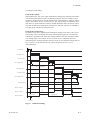
The following functions are programmable for contact outputs.
(1) Abnormal, (2) High-high alarm, (3) High alarm, (4) Low-low alarm, (5)
Low-alarm, (6) Maintenance, (7) Calibration, (8) Range switching answerback, (9) Warm-up, (10) Calibration-gas pressure decrease (answerback of
contact input), (11) Blowback start, (12) Process alarm (answerback of contact
input), (13) Calibration coefficient alarm, (14) Internal temperature rise alarm.
Contact output 5 is set to normally operated, fixed error status.
Contact Output for Individual Channel Fail: Output to each channel
Normally energized.
Each channel cards provides a failure contact output.
(1)Abnormal cell, (2)abnormal cell temperature(high/low), (3)abnormal channel
card, (4)abnormal control card, (5)abnormal card commu nication
Contact Input: Two points, contact input
The following functions are programmable for contact inputs:
(1) Calibration-gas pressure decrease alarm, (2) Range switching, (3) External
calibration start, (4) Process alarm (if this signal is received, the heater power
turns off), (5) Validation start, (6) Blow-back start
Self-diagnosis: Abnormal cell, abnormal cell temperature(high/low), abnormal channel
card, abnormal control card, abnormal card communication
Calibration: Method; zero/span calibration
Calibration mode; automatic, semi-automatic and manual (All are operated
interactively with an LCD touchscreen). Either zero or span can be skipped.
Zero calibration-gas concentration setting range; 0.3 to 100 vol% O2 (0.01 vol%O2
in smallest units). Span calibration-gas concentration setting range: 4.5 to 100
vol% O2 (0.01 vol% O2 in smallest units). Use nitrogen-balanced mixed gas
containing 0 to 10 % scale of oxygen, and 80 to 100 % scale of oxygen for
standard zero gas and standard span-gas respectively.
Calibration period; date/time setting; maximum 255 days/23hours.
IM 11M12D01-01E
2-15
FOUNDATION Fieldbus communication function
The bi-directional digital communication as standard for FOUNDATION Fieldbus that is
established by Fieldbus foundation.
Interface : FOUNDATION Fieldbus H1 (communication speed : 31.25 kb/s)
Physical layer type :
113 (standard-power signaling, bus powered, non I.S.)
Communication line condition:
power supply----9 to 32 VDC, current supply----15 mA (Max)
Signal insulation :
communication terminal to grand terminal, dielectric strength 500 Vrms
(50/60 Hz, 1 min).
Device : Link master
Function block :
AI block :
3 blocks (1 block for each channels)
Transfer the data of averaging oxygen concentration to other instruments.
DI block :
2 blocks
Transfer the status of error and alarm to other instruments.
MAI block
1 block (8 channels)
Transfer the data of oxygen concentration to other instruments.
MAO block
1 block (8 channels)
Import the data of other instruments.
2-16
IM 11M12D01-01E
2. Specifications
d Model and Suffix Code
1. Detector
Refer to GS 11M12A01-01E for a detailed explanation of the detector specifications
and available accessories.
2. Averaging Converter
Model
Option
Code
Suffix Code
AV550G
Base (*1)
Specification
Averaging Converter
-A
-B
Number of Channel
Card (*2)
4 Channel Base
8 Channel Base
-A1
-A2
-A3
-A4
-A5
-A6
-A7
-A8
-B1
-B2
-B3
-B4
-B5
-B6
-B7
-B8
1 Oxygen Channel Card, Common Isolation
2 Oxygen Channel Cards, Common Isolation
3 Oxygen Channel Cards, Common Isolation
4 Oxygen Channel Cards, Common Isolation
5 Oxygen Channel Cards, Common Isolation
6 Oxygen Channel Cards, Common Isolation
7 Oxygen Channel Cards, Common Isolation
8 Oxygen Channel Cards, Common Isolation
1 Oxygen Channel Card, Individual Isolation
2 Oxygen Channel Cards, Individual Isolation
3 Oxygen Channel Cards, Individual Isolation
4 Oxygen Channel Cards, Individual Isolation
5 Oxygen Channel Cards, Individual Isolation
6 Oxygen Channel Cards, Individual Isolation
7 Oxygen Channel Cards, Individual Isolation
8 Oxygen Channel Cards, Individual Isolation
Japanese
English
French
German
-J
-E
-F
-G
Display
100 / 115 V AC
230 V AC (*3)
-1
-2
Power supply
HART communication
FOUNDATION Fieldbus communication (*4)
-E
-F
Communication
/SCT
/24
/G
Options
Stainless steel tag plate
24 Voltage output for Solenoid valve
Cable gland (Numbers in
) (*5)
T02.EPS
(*1) Select code "-B" (8 Channel Base) when future expansion exceeding 4 channels is expected.
By so doing, the expansion can be made economically.
(*2) Common isolation is recommended, when the same instrument receives the analog
outputs from each channel card. Individual isolation is recommended to prevent the
trouble by mutual interference, when different instrument receives the analog outputs
from each channel card.
(*3) When suffix code "-2" (230 V AC) is selected, select code "-A" (4 Channel Base).
(*4) When suffix code "-F" (FOUNDATION Fieldbus communication) is selected, used exclusively
for communication.
(*5) Input 01 to 30 in h h.
3. Channel Code
Model
Suffix Code
Option
Code
AV55CM
Number of
Channels (*1)
-A1
-A2
-A3
-A4
-A5
-A6
-A7
-A8
-B1
-B2
-B3
-B4
-B5
-B6
-B7
-B8
1 Oxygen Channel Card, Common Isolation
2 Oxygen Channel Cards, Common Isolation
3 Oxygen Channel Cards, Common Isolation
4 Oxygen Channel Cards, Common Isolation
5 Oxygen Channel Cards, Common Isolation
6 Oxygen Channel Cards, Common Isolation
7 Oxygen Channel Cards, Common Isolation
8 Oxygen Channel Cards, Common Isolation
1 Oxygen Channel Card, Individual Isolation
2 Oxygen Channel Cards, Individual Isolation
3 Oxygen Channel Cards, Individual Isolation
4 Oxygen Channel Cards, Individual Isolation
5 Oxygen Channel Cards, Individual Isolation
6 Oxygen Channel Cards, Individual Isolation
7 Oxygen Channel Cards, Individual Isolation
8 Oxygen Channel Cards, Individual Isolation
-A
Option
Specification
Channel Card
Always -A
/K1
Expansion power supply unit for dry contact
(*2)
output of solenoid valve output.
/K2
Expansion power supply unit for 24 volt
(*3)
output of solenoid valve output.
T03.EPS
(*1) -A h are common Isolation types
-B h are Individual Isolation types
Up to 4 channel cards can be added in the 230 VAC version.
(*2) Expansion power supply unit is required, when using the 4 channel base and extending the number of
channel cards to five or more.
The expansion power supply unit cannot be added in the 230 VAC version.
(*3) Expansion power supply unit is required, when using the 4 channel base and extending the number of
channel cards to five or more. Available only in U.S.
IM 11M12D01-01E
2-17
• External Dimensions
Unit: mm
480
465
R3
165.1
R3
.5
R3
17.3
35.5
150
.5
R3
480 (without cable gland and grommet)
266.7
300
5
R3.
166.5
457
4-knobs
Extension view
Distance between mounting hole
465
7
10-M5
holes
150
165.1
300
266.7
6
200
Maintenance space
200
800
300
200
• AV550G Standard Accessories
Name
Part No
Quantity
Remarks
Fuse
A1112EF
2
2.5A
L9827AS
1
Hexagonal
Allen Wrench
For lock screw.
T01.EPS
2-18
IM 11M12D01-01E
2. Specifications
2.5
ZA8F Flow Setting Unit
2.5.1
ZA8F Flow Setting Unit
This flow setting unit is applied to the reference gas and the calibration gas in a system
configuration (System 1).
This unit consists of a flow meter and flow control valves to control the flow of calibration gas and reference air.
Standard Specifications
FIowmeter: Calibration gas; 0.1 to 1.0 l/min. Reference air; 0.1 to 1.0 l/min.
Construction: Dust-proof and rainproof construction
Case Material: SPCC (Cold rolled steel sheet)
Painting: Baked epoxy resin, Dark-green (Munsell 2.0 GY 3.1/0.5 or equivalent)
Pipe Connections: Rc1/4 or 1/4FNPT
Reference Air pressure: Clean air supply of measured gas pressure approx. 50 kPa G
(or measured gas pressure plus approx. 150 kPa G when a check valve is used)
pressure at inlet of the auto-calibration unit.(Maximum 300 kPaG)
Air Consumption: Approx. 1.5 l/min
Weight: Approx. 2.3kg
Calibration gas (zero gas, span gas) flow 0.7 l/m (at calibration time only)
Note
Use instrument air for span calibration gas, if no instrument air is available, contact
YOKOGAWA.
Model
Suffix code
Joint
Style code
Option code
Description
Flow setting unit
ZA8F
-J
-A
*B
Rc 1/4
With 1/4" NPT adapter
Style B
T2.5E.EPS
IM 11M12D01-01E
2-19
• External Dimensions
Unit: mm
f6 hole
180
7
140
REFERENCE
CHECK
ZERO
SRAN
Zero gas outlet Span gas inlet
Zero gas inlet
26
Reference air outlet
222.8
235.8
REFERENCE
20
35
35
35
35
20
8
35
70
4-Rc1/4
Piping connection
port
Instrument air inlet
CHECK
OUT
Flow
meter
REF
OUT
Flow
meter
AIR IN
ZERO
GAS IN
SPAN
GAS IN
Instrument air
Approx 1.5 l/min.
Airset
Air pressure ;
without check valve ; measured gas pressure 1 approx.50 kPaG
with check valve ; measured gas pressure 1 approx.150 kPaG
F2.6E.EPS
2-20
IM 11M12D01-01E
2. Specifications
2.6
Other Equipment
2.6.1
Dust Filter for the Detector (Part No.: K9471UA)
This filter is used to protect the detector sensor from a corrosive dust component or from
a high concentration of dust when the oxygen concentration in utility boilers or concrete
kilns are to be measured.
This filter requires a measurement gas flow of 1m/sec or faster, for circulation of the gas
in the sensing part.
• Standard specification
Applicable detector: Standard-type detector for general-use (the measurement gas
flow should be approximately perpendicular to the probe.)
Mesh: 30 microns
Material: Sic (Filter), SUS316 (JIS)
Weight: Approx. 0.2 kg
Part No.
Description
K9471UA
Filter
K9471UX
Tool
T2.7E.EPS
Unit : mm
SiC Caborundum filter
f51
32
10
Increasing of insertion length
F2.8E.EPS
2.6.2
Dust Guard Protector (Part No.: K9471UC)
Recommended to be used when sample gas is likely to flow directly into the cell due to
its flow direction in the stack or the like, flammable dust may go into the cell, or water
drops are likely to fall and remain in the cell during downtime or the like due to the
installation position.
Material: SUS316
Weight: Approx. 0.3 kg
[
50.8
Increasing of insertion length
100
4-[ 6
122
F11-1.eps
IM 11M12D01-01E
2-21
2.6.3
Auxiliary Ejector for High Temperature (Part No. E7046EC or E7046EN)
This ejector is used where pressure of measured gas for high temperature detector is
negative. This ejector consists of an ejector assembly, a pressure gauge and a needle
valve.
Standard Specifications
Ejector Assembly
Ejector Inlet Air Pressure: 29 to 68 kPa G
Air Consumption: Approx. 30 to 40 l/min
Suction gas flow rate: 3 to 7 l/min
Connection to high-temperature probe adapter: R 1/2
Connection: Rc1/4 or 1/4 FNPT, SUS304 (JIS)
Tube Connection: ([6/[4 mm or 1/4 inch copper tube or stainless tube)
Pressure Gauge Assembly
Type: JIS B7505, A1.5U3/8 x75
Material in Contact with Gas: SUS316 (JIS)
Case Material: Aluminum alloy (Paint color; black)
Scale: 0 to 100 kPa G
Bushing (G3/8 x Rc1/4 or 1/4NPT, SUS304 (JIS))
Needle Valve
Connection: Rc1/4 or 1/4FNPT
Material: SUS316 (JIS)
Part No.
Description
E7046EC
RC 1/4 [6 / [4 TUBE joint: SUS304 (JIS)
E7046EN
1/4 NPT, 1/4 TUBE joint: SUS304 (JIS)
T2.8E.EPS
2-22
IM 11M12D01-01E
2. Specifications
E7046EC ; Piping connections, Rc1/4( p part) or Rc1/4( pp part ),
E7046EN ; Piping connections,1/4NPT female ( p part) or 1/4NTP male( pp part )
Pressure gauge
39
f63f4 or 1/4 inch, conduit (stainless)
Needle
valve
f43
Approx.88
Ejector assembly
Height when
fully open
Approx.67
lnstrument
air inlet
PT 1/2 male
Approx.
70
pp
Detector
38
p
p
p
40
Not included in high
temperature use
auxiliary ejector.
20
Auxiliary ejector for
high-temperature
mounting place use.
Needle
valve
Pressure gauge
Po
Ejector
Qa
Air
source
L
Pg
Qg
1)
Po (kPa)
200
2)
Qa (l/min)
40
P= 0.5
100
0
30
5
L (m)
10
15
0
Pressure setting characteristics
40
P (kPa)
60
80
Air consumption characteristics
Gas
Pg (kPa)
4)
3)
Po (kPa)
P
(kPa)
Pg (kPa)
Qa (l/min)
Qg (l/min)
L
(m)
Qg (l/min)
Gas Pressure:
8
0 kPa
-1.0
-0.5
4
0
0
Gas pressure : -15 Pa
60
40
P (kPa)
80
Suction pressure characteristics
40
60
: Pressure setting
: Drive pressure (at the ejector entrance)
: Suction pressure
: Air consumption
: Suction flow
: Distance between the ejector and the pressure
gauge
80
P (kPa)
Suction flow characteristics
F2.9E.EPS
(Note) Pipes and connectors are not provided.
IM 11M12D01-01E
2-23
< Pressure setting for the auxiliary ejector for high-temperature use >
Pressure supply for the auxiliary ejector should be set so that the suction flow of the
measured gas becomes approximately 5 l/min.
To set this, proceed as follows:
(1) In Graph 4, draw a horizontal line from the 5 l/min point. on the vertical axis
(Suction flow: Qg) toward the gas pressure line to be used, to find the point of
intersection.
Draw a line vertically down from the point of intersection to the axis to find the
drive pressure, P (at the ejector entrance).
(2) In Graph 1, determine Po (pressure setting) from L (the distance between the ejector
and the pressure gauge).
(3) Open the needle valve to supply air for the ejector to the pressure gauge until it
indicates the pressure setting, Po.
Note
Qg (the suction flow) may require change according to the conditions of use. Refer to
Section 3.2.2 and Section 4.1.4 for details.
Graph explanation
1) Graph 1 is to compensate for pressure loss in piping between the ejector and the
pressure gauge, and find Po (pressure setting).
2) Graph 2 shows correlation between P (drive pressure) and Qa (air consumption).
3) Graph 3 shows correlation between P (drive pressure) and Pg (suction pressure; when
the measured gas inlet of the ejector is closed).
4) Graph 4 shows correlation between P (drive pressure) and Qg (suction flow) for each
gas pressure.
2.6.4
Stop Valve (Part No. L9852CB or G7016XH)
This valve is mounted on the calibration gas line in the system using flow setting unit
for manual calibration.
Standard Specifications
Connection: Rc 1/4 or 1/4 FNPT
Material: SUS 316 (JIS)
Weight: Approx. 80 g
Description
Part No.
L9852CB
Joint: RC 1/4, Material: SUS 316 (JIS)
G7016XH
Joint: 1/4 NPT, Material: SUS316 (JIS)
T2.9E.EPS
55
(Full open length)
43
Rc1/4 or 1/4NPT
40
F15.EPS
2-24
IM 11M12D01-01E
2. Specifications
2.6.5
Check Valve (Part No. K9292DN or K9292DS)
This valve is mounted on the calibration gas line in the system such as the one using
flow setting units for manual calibration or the one performing when unburnt gas is
generated.
This valve prevents the process gas from entering the calibration gas line. Although it
functions as a stop valve, operation is easier than a stop valve as it does not require
opening/closing at each calibration.
Screw a check valve, instead of a stop valve into the calibration gas inlet of the detector.
Standard Specifications
Connection: Rc1/4 or 1/4FNPT
Material: SUS304 (JIS)
Pressure: 70 kPa G or more and 350 kPa G or less
Weight: Approx. 40 g
Description
Part No.
K9292DN
Joint: RC 1/4, Material: SUS304 (JIS)
K9292DS
Joint: 1/4 NPT, Material: SUS304 (JIS)
T2.10E.EPS
Unit : mm
K9292DN : Rc 1/4 (A part), R 1/4(B part)
K9292DS : 1/4FNPT (A part),1/4NPT(Male)(B part)
A
Approx.19
B
Approx.54
F2.11E.EPS
IM 11M12D01-01E
2-25
2.6.6
Air Set
This set is used to lower the pressure when instrument air is used as the reference and
span gases.
• Part No.K9473XH or K9473XJ
Standard Specifications
Primary Pressure: Max. 2 MPa G
Secondary Pressure: 9.8 to 196 kPa G
Connection: Rc1/4 or 1/4NPT(F) (includes joint adapter)
Weight: Approx.1 kg
Part No.
Description
K9473XH
Joint: Rc 1/4, Material: Aluminum
K9473XJ
Joint: 1/4 NPT (F) , Material: Body; Aluminum, Adapter; SUS316
T2.11E.EPS
Unit: mm
Dimensions in parentheses are approximate.
(43.5)
(97)
IN
(135.5)
OUT
(53.5)
(63)
[54
60
48
69.5
40
42
8
7
28
18.5
(116)
Bracket Mounting Dimensions
K9473XH: Piping connection (IN: Primary side, OUT: Secondary side), Rc1/4
K9473XJ: Piping connection (IN: Primary side, OUT: Secondary side), 1/4NPT(F)
2-26
IM 11M12D01-01E
2. Specifications
• Part No. G7004XF or K9473XG
Standard Specifications
Primary Pressure: Max. 1 MPa G
Secondary Pressure: 20 to 500 kPa G
Connection: Rc1/4 or 1/4 FNPT with joint adapter
Part No.
Description
G7004XF
Joint: Rc 1/4, Material: Zinc Alloy
K9473XG
Joint: 1/4 FNPT , Material: Zinc Alloy
with adapter
T2.13E.EPS
d External Dimensions
Unit : mm
View A
Panel cut dimensions
Horizontal
mounting
22
Vertical
mounting
[15
40
+0.5
2-2.2 -0
40
2-[6.5
max. 55
2-[6 screw depth 10
Secondary
pressure
gauge
Secondary
Panel (Vertical
mounting)
A
88
Primary
Max. 210
[74
Panel (Horizontal
mounting)
G7004XF: Rc 1/4
K9473XG: 1/4NPT connector
Approx. 122
IM 11M12D01-01E
2-27
2.6.7
Zero Gas Cylinder (Part No. G7001ZC)
The gas from this cylinder is used as the calibration zero gas and detector purge gas.
Standard Specifications
Capacity: 3.4 l
Filled pressure: 9.8 to 12 MPa G
Composition: 0.95 to 1.0 vol% O2 in N2
(Note) Export of such high pressure filled gas cylinder to most countries is prohibited
or restricted.
485
325
Unit : mm
[140
2.6.8
Weight : Approx. 6 kg
F213E.EPS
Cylinder Regulator Valve (Part No. G7013XF or G7014XF)
This regulator valve is used with the zero gas cylinders.
Standard Specifications
Pressure gauge: Primary 0 to 25 àa G, Secondary 0 to 0.5 MPa G
Connection: Inlet W22 14 threads, right hand screw Outlet Rc1/4 or 1/4NPT(F)
Material: Brass body
Approx.112
Primary
Secondary
pressure gauge pressure gauge
0.5 MPaG
25 MPaG
Regulator handle
W22 (Righthanded screw)
ACH
IN
´J
HO
TAK
I
ACH
O
IH
TAK
Stop valve
J ´
p Outlet
Secondary
safety valve
Primary
safety valve
Approx. 59
Approx. 82
Approx. 163
2-28
Approx. 174
Part No.
p Outlet
G7013XF
Rc1/4
G7014XF
1/4 NPT female screw
IM 11M12D01-01E
2. Specifications
2.6.9
Calibration Gas Unit Case (Part No. E7044KF)
This case is used to store the zero gas cylinders.
Standard Specifications
Case Paint: Baked epoxy resin, Jade green (Munsell 7.5 BG 4/1.5)
Installation: 2B pipe mounting
Material: SPCC (Cold rolled steel sheet)
Weight: 3.6 kg, Approx. 10 kg with gas cylinder
(Note) Export of such high pressure filled gas cylinder to most countries prohibited or
restricted.
Unit: mm
324
Pressure regulator
G7013XF/
G7014XF
200
180
Zero gas cylinder
(G7001ZC)
496
(Note) E7044KF (case assembly) has no zero gas cylinder
and pressure regulator.
2B pipe ( f60.5)
F2.15E.EPS
IM 11M12D01-01E
2-29
2.6.10 Model ZR22A Heater Assembly
Style: S2
Model
Suffix code
Heater Assembly for ZR22G
ZR22A
Length
(p1)
Description
Option code
0.15 m
0.4 m
0.7 m
1m
1.5 m
2m
2.5 m
3m
-015
-040
-070
-100
-150
-200
-250
-300
Jig for change
with Jig
None
-A
-N
Reference air (*3)
(*2)
-A
Reference air Natural convention
External connection (Instrument air)
-B
-C
Pressure compensated (for ZR22G S2)
Pressure compensated (for ZR22G S1)
p1 Suffix code of length should be selected as same as ZR22G installed.
p2 Jig part no. is K9470BX to order as a parts after purchase.
p3 Select appropriately among "-A", "-B", "-C" according to the reference air supply method and style.
(Note) The heater is made of ceramic, do not drop or subject it to pressure stress.
T23.EPS
Unit : mm
30
[ 45
(K9470BX)
K9470BX
Jig for change
[ 21.7
d External Dimensions
L612
L length
F2.16E.EPS
2-30
Model & Code
L
Weight (kg)
ZR22A-015
302
Approx. 0.5
ZR22A-040
552
Approx. 0.8
ZR22A-070
852
Approx. 1.2
ZR22A-100
1152
Approx. 1.6
ZR22A-150
1652
Approx. 2.2
ZR22A-200
2152
Approx. 2.8
ZR22A-250
2652
Approx. 3.4
ZR22A-300
3152
Approx. 4.0
IM 11M12D01-01E
2. Specifications
IM 11M12D01-01E
2-31
3. Installation
3.
Installation
This chapter describes installation of the following equipment:
Section 3.1
Detector (except model ZR22G-015)
Section 3.2
Detector (model ZR22G-015)
Section 3.3
Averaging Converter
Section 3.4
ZA8F Flow Setting Unit
Section 3.5
Calibration Gas Unit Case (E7044KF)
3.1
Installation of the Detector
3.1.1
Location
The following should be taken into consideration when installing the detector:
(1) Easy and safe access to the detector for checking and maintenance work.
(2) Ambient temperature of not more than 1508C, and the terminal box should not
affected by radiant heat.
(3) A clean environment without any corrosive gases.
CAUTION
• A natural convection type detector (model ZR22G-h-h-h-C), which uses ambient air
as reference gas, requires that the ambient oxygen concentration be constant.
(4) No vibration.
(5) The measurement gas satisfies the specifications described in Chapter 2.
(6) No measured gas-pressure fluctuations.
3.1.2
Probe Insertion Hole
Includes those analyzers equipped with a probe supporter and probe protector.
When preparing the probe insertion hole, the following should be taken into consideration:
CAUTION
• The outside dimension of detector may vary depending on its options. Use a pipe that
is large enough for the detector. Refer to Figure 3.1 for the dimensions.
• If the detector is mounted horizontally, the calibration gas inlet and reference gas inlet
should face downwards.
• When using the detector with pressure compensation, ensure that the flange gasket
does not block the reference air outlet on the detector flange. If the flange gasket
blocks the outlet, the detector cannot conduct pressure compensation. Where necessary, make a notch in the flange gasket. Confirm the outside dimensions of the
detector in Chapter 3.8 of IM 11M12A01-02E before installation.
• The sensor (zirconia cell) at the probe tip may deteriorate due to thermal shock if
water drops are allowed to fall on it, as it is always at high temperature.
IM 11M12D01-01E
3-1
(1) Do not mount the probe with the tip higher than the probe base.
(2) If the probe length is 2.5 meters or more, the detector should be mounted vertically
(no more than a 58 tilt).
(3) The detector probe should be mounted at right angles to the measurement gas flow or
the probe tip should point downstream.
Figure 3.1 illustrates an example of the probe insertion hole.
Bounds of the probe
insertion hole location
(vertical)
Flange matches
the detector size
100 mm
*1
Type
Standard
With dust filter
With probe protector
Outside diameter of detector
50.8 mm in diameter (Note)
51 mm in diameter (Note)
60.5 mm in diameter (Note)
(horizontal)
*1
Note
100 mm
Four-hole flange
Eight-hole flange
(Note)
When using the detector with pressure compensation, ensure that the flange
gasket does not block the reference air outlet on the detector flange. If the flange
gasket blocks the outlet, the detector cannot perform pressure compensation.
Where necessary, make a notch in the flange gasket.
F3.1E.EPS
Figure 3.1 Example of forming probe insertion hole
3.1.3
Installation of the Detector
CAUTION
• The cell (sensor) at the tip of the detector is made of ceramic (zirconia). Do not drop
the detector, as impact will damage it.
• A gasket should be used between the flanges to prevent gas leakage. The gasket
material should be heatproof and corrosion-proof, suited to the characteristics of the
measured gas.
The following should be taken into consideration when mounting the general-use
detector:
<General-use detector>
(1) Make sure that the cell mounting screws (four) at the probe tip are not loose.
If a dust filter (see Section 2.6.1) is used, make sure it is properly attached to the
detector. Refer to Section 3.1.4 for installation of the dust filter.
(2) Where the detector is mounted horizontally, the calibration gas inlet and the reference gas inlet should face downward.
3-2
IM 11M12D01-01E
3. Installation
3.1.4
Installation of the Dust Filter( Part No K9471UA), etc
CAUTION
• The dust filter is used to protect the Zirconia sensor from corrosive dust or a high
concentration of dust such as in utility boilers and concrete kilns. If a filter is used in
combustion systems other than these, it may have adverse effects such as response
delay. These combustion conditions should be examined carefully before using a
filter.
• The dust filter requires gas flow of 1 m/sec. or faster at the front surface of the filter
(K9471UA).
When you specify option code /F1, the detector is shipped with the dust filter mounted.
Follow this procedure replace the filter on the detector. It is recommended that you read
Chapter 11 prior to filter mounting, for it is necessary to be familiar with the detector’s
construction, especially the sensor assembly.
(1) Mount the dust filter assembly by putting it on the end of the detector and screw the
assembly clockwise. Put a hook pin wrench (K9471UX), [52 to 55 in diameter, into
the hole on the assembly to fasten or remove it.
Apply a heat-resistant coating (see Note 1) to the threads on the detector.
When remounting Filter assembly after having once removed it from the detector,
reapply the heat-resistant coating.
Note 1: As the detector is heated to 7008C, it is recommended to use heat-resistant
coating on the threads to prevent seizing up. Name of the heat-resistant coating
material: NEVER SEIZE NICKEL SPECIAL”.
Unit : mm
SiC Carborundum filter
Detector
f 51
32
Attach the filter
unit to the tip of
the detector
by screwing
it clockwise.
Screw
10
Additional length
F3.2E.EPS
Figure 3.2 Installation of the dust filter
IM 11M12D01-01E
3-3
3.1.5
Procedures for installing the dust guard protector (K9471UC)
The ZR22G detector is shipped with the dust guard protector when the option code “/
F2” is specified in case of ordering the detector. The protector should be used when
preventing dusts and water drops from lowering the detector performance is desired.
Screw the protector on the top of the detector so as to cover the top. When attaching or
detaching the protector, perform by hooking holes of its side with a hook pin wrench for
[52-55 hole( Pin diameter 4.5 mm: P/N K9741UX or the like) or by pass a screwdriver
through the holes. When re-attaching the protector after detaching it, apply the “Never
Seize Nickel Special” to it.
[
50.8
Increasing of insertion length
100
4-[ 6
122
F11-1.eps
3.1.6
Detector with a probe protector (Model ZO21R-L-hhh-h *B for enhance forth
The detector is used with a probe protector to support the probe (ZR22G) when the
probe length is 2.5m or more and it is mounted horizontally.
(1) Put a gasket (provided by the user) between the flanges, and mount the probe
protector in the probe insertion hole.
(2) Make sure that the cell assembly mounting screws (four) at the probe tip are not
loose.
(3) Mount the detector so that the reference gas and calibration gas inlet faces downward.
Flow direction of the
measurement gas
Gasket (t1.5)
Unit: mm
1050,1550,2050
[60.5
Notch
Probe top
Reference gas inlet
Calibration gas inlet
F3.3E.EPS
Figure 3.3 Probe protector (supporting the mounting strength)
3-4
IM 11M12D01-01E
3. Installation
3.1.7
Detector with a probe protector (Model ZO21R-L-hhh-h *B for dust wear
protect
The detector is used with a probe protector to prevent the sensor from being worn by
dust particles when there is a high concentration of dust and gas flow exceeds 10m/s
(fine-carbon boiler or fluid-bed furnace).
(1) Put a gasket (provided by the user) between the flanges, and mount the probe
protector in the probe insertion hole. The probe protector should be installed so that
the notch is downstream of the measurement gas flow.
(2) Make sure that the cell assembly mounting screws (four) at the probe tip are not
loose.
(3) Where the detector is mounted horizontally, the reference gas and calibration gas
inlet should face downward.
CAUTION
When the probe protector is used in the Zirconia Oxygen Analyzer version with
pressure compensation (-P), instrument air leaking from the probe protector may
affect the measured value.
1050,1550,2050
Gasket (t1.5)
Unit: mm
Direction of the measurement gas flow
Probe top
Mount the protector so that the notch is
or the downstream side of the gas flow.
F3.4E.EPS
Reference gas inlet
Calibration gas inlet
Figure 3.4 Mounting of detector with a probe protector
IM 11M12D01-01E
3-5
3.2
Installation of the Detector (Model ZR22G-015)
3.2.1
Installation Location
This model detector is used with the High-temperature Probe Adapter (Model ZO21P-H)
when the temperature of sample gas exceeds 7008C, or when it is required due to
maintenance spaces.
The following should be taken into consideration when installing the detector:
(1) Easy and safe access to the detector for checking and maintenance work.
(2) Ambient temperature of not more than 1508C and the terminal box should not be
exposed to radiant heat.
(3) A clean environment without any corrosive gases.
(4) No vibration.
(5) The measured gas should satisfy the specifications described in Chapter 2.
3.2.2
Usage of the High-temperature Probe Adapter (Model ZO21P-H)
During analysis, the surface temperature of the probe adapter should be within the range
from the dew point of the measured gas and 3008C to prevent ejector clogging, gasket
deterioration or bolt scoring.
Where the dew point of the measured gas is not known, keep within the range 2008C to
3008C.
The temperature shall be measured at the probe in the probe adapter and the surface of
the blind flange at the opposite side.
When the surface temperature is not within the above range, the following measures can
be taken to change the temperature.
<When the surface temperature exceeds 3008C>
(1) When the furnace pressure is negative, lower the pressure setting to reduce induction
flow of the measurement gas.
Refer to Section 2.6.3, Auxiliary Ejector for High Temperature, for the setting of
induction flow.
When you reduce induction flow, ensure that the ejector inducts air when the furnace
pressure fluctuates.
(2) When the furnace pressure is positive, close the needle valve for the sample gas
outlet to reduce the exhaust gas flow. Refer to Section 4.1.4, Piping to the Hightemperature Probe Adapter.
(3) When the probe adapter is surrounded by a heat insulator, remove the heat insulator.
Ensure that the temperature of the probe adapter does not fall below the dew point of
the gas in winter.
(4) To prevent temperature rises due to radiant heat, insert heat insulator between the
wall of the furnace and the probe adapter.
(5) To prevent temperature rises from thermal conduction, place the mounting flange as
far from the wall of the furnace as possible.
3-6
IM 11M12D01-01E
3. Installation
<When the surface temperature is less than 2008C or the dew point of the measurement gas>
(1) When the furnace pressure is negative, raise the analyzer pressure to increase
induction flow of the measurement gas.
Refer to Section 2.6.3, Auxiliary Ejector for High-temperature Use, for the setting of
induction flow.
If there is much dust in the gas, the ejector may become clogg is induction flow
increases.
(2) When the furnace pressure is positive, open the needle valve for the sample gas
outlet to increase the gas flow.
Refer to Section 4.1.4, Piping to the High-temperature Probe Adapter.
(3) Warm the probe adapter. Refer to Section 4.2.4, Piping to the High-temperature
Probe Adapter. Ensure that its temperature does not drop below freezing point in
winter.
(4) When the surface temperature is still less than 2008C or the dew point of the measurement gas, even if the above measures have been taken, warm the probe adapter
using a heat source such as steam.
3.2.3
Probe Insertion Hole
A high-temperature detector consists of a ZR22G-015 Detector and ZO21P Hightemperature Probe Adapter. When forming the probe insertion hole, the following should
be taken into consideration:
(1) If the probe is made of silicon carbide (SiC), the probe hole should be formed so that
the probe is mounted vertically (no more than a 58 tilt).
(2) In the case where the probe is made of stainless steel and the probe adapter is to be
mounted horizontally, the probe hole should be formed so that the probe tip is not
higher than the probe base.
Figure 3.5 illustrates examples of the probe insertion hole.
JIS 5K 50 FF (equivalent) or
100mm
ANSI Class 150 4 RF
(equivalent) flange
A space of 52 mm or
100mm
more in diameter, and
long enough the length
of the probe
A space of 52 mm or more
in diameter, and long enough
for the length of the probe
Never mount the probe
JIS 5K 50 FF (equivalent)
with its tip higher than
or ANSI Class 150 4 RF
the base
(equivalent) flange
The allowable margin for probe
tilt is within
658.
An SiC probe shall be mounted vertically.
Horizontal mounting is used with a SUS probe.
F3.5E.EPS
Figure 3.5 Examples of the probe insertion hole
IM 11M12D01-01E
3-7
3.2.4
Mounting of the High-Temperature Detector
Note
Ceramic (zirconia) is used in the sensor (cell) portion on the detector probe tip. Care
should be taken not to drop the detector during installation.
The same applies to a probe made of silicon carbide (SiC).
A gasket should be used on the flange surface to prevent gas leakage. The gasket
material should be selected depending on the characteristics of the measurement gas. It
should be heatproof and corrosion-proof. The parts, which should be supplied by the
user, are listed in Table 3.2.
Table 3.2 Accessories for mounting high-temperature probe adapter
Mounting flange specification
Accessory name
JIS 5K 50 FF (equivalent)
Gasket
ANSI Class 150 RF (equivalent)
Number
1
Bolt (M12 by 50)
4
Nut (M12)
4
Washer (for M12)
8
Gasket
1
Bolt (M16 by 60)
8
Nut (M16)
Washer (for M16)
Note
Heatproof and corrosionproof
Heatproof and corrosionproof
8
16
T3.2E.EPS
A high-temperature detector should be mounted as follows:
(1) It is recommended to mount the detector vertically. When it is impossible due to the
physical arrangements and the detector is mounted horizontally, ensure that the probe
tip be placed no higher than the probe base.
(2) When mounting a high-temperature probe adapter, be sure to insert a gasket between
the flanges to prevent gas leakage. When the furnace pressure is negative, ensure that
there is no leakage of air into the furnace.
(3) When mounting the detector in a position other than vertical, the cable inlet should
face downward.
(4) When installing the detector in a low-temperature location such as in the open air,
cover the probe adapter including the ejector with a heat insulator (e.g. ceramic
wool) to keep it warm and to prevent condensation of drain on the ejector.
Wiring connection
Mount the probe so that
the probe tip is not higher
than the probe base.
Wiring connection
When using an SiC probe, mount the probe vertically
with an allowable tilt of ±5°.
F3.6E.EPS
Figure 3.6 Mounting of the High-temperature Detector
3-8
IM 11M12D01-01E
3. Installation
3.3
Installation of the Averaging Converter
The averaging converter is designed for indoor installation and should be installed in the
instrument panel in a control room. For outdoor installation, the averaging converter
should be installed in an outdoor instrument panel protected from direct sunlight and the
weather.
DANGER
High voltages are present inside the averaging converter. To prevent unintentional
opening of the front cover, it is securely attached by a lock screw on the right side of
the case. Loosen the lock screw to remove the front cover, and securely tighten the
lock screw after the front cover has been attached.
How to remove the front cover
• Loosen the 4 knob bolts by hand, and then loosen the lock screw with the Allen
wrench supplied.
• Remove the front cover by lifting up slightly then pulling away from the case.
How to attach the front cover
• Attach the front cover, aligning the slots on the sides of the cover with the knob bolts
on the case, and then pull the cover down until it is seated firmly.
• Hand tighten the knob bolts, and then securely tighten the lock screw with the Allen
wrench supplied.
Knob Bolt
Lock Screw
Figure 3.7
IM 11M12D01-01E
How to Remove/Attach the front Cover
3-9
3.3.1
Installation Location
Follow the guidelines below when selecting a location for the averaging converter.
(1) The touch screen display should be clearly visible and easily accessible for key
operation: the display at eye level is recommended.
(2) A wall or construction should be strong enough to support the weight of the
converter.
(3) The converter should be easily accessible for inspections and maintenance.
(4) The ambient temperature should be in the range of -5 to 508C and the temperature
variation should be small: the daily temperature range within 158C is recommended.
(5) The humidity should be in the range of 10 to 85%RH and no condensation may
occur.
(6) No corrosive gases are present.
(7) No dust exists.
(8) There is minimal vibration.
(9) The converter should be near the detectors: the two-way resistance between detector
and converter should not exceed 10V.
DANGER
• The averaging converter is heavy. Take extra care not to accidentally drop it.
Installation work should be done by an adequate number of people.
CAUTION
The averaging converter is heavy (100/115 VAC version: approx. 13 kg, 230 VAC
version: approx. 25 kg) so needs to be installed on a wall or construction strong
enough to support.
3.3.2
Installation in an Instrument Panel
When installing the averaging converter in an instrument panel, operability,
maintainability, and environmental resistance should be considered.
(1) Installation Space and Relationship to Peripheral Devices
Follow the instructions below to determine the positions of the averaging converter and
peripheral devices.
• Do not place heat-generating devices in close proximity of the averaging converter:
specially, avoid a place under the averaging converter.
• Do not place power related devices such as transformers or electromagnetic switches
in close proximity of the averaging converter.
• Segregate wiring ducts for signal lines and those for power lines and do not place in
close proximity.
Figure 3.8 shows the requirements for the mounting holes for the averaging converter.
See Section 2.4 for the dimensions of the averaging converter and maintenance
clearance.
3-10
IM 11M12D01-01E
3. Installation
Unit: mm
6-M5 screws
300 [267]
150 [165]
Note: Dimensions in inches are
given in parentheses.
465
F3302.EPS
Figure 3.8 Mounting holes
(2) Preventing Excessive Temperature Rise in an Instrument Panel
Use a cooling method such as one of those shown in Figure 3.9 if there is a danger of
the temperature inside an instrument panel exceeding the temperature range limits.
£
£
£
£
£
£
£
£
£
Fan
£
£ £ £
AV550G
AV550G
AV550G
£ £
£
£
£
£
Natural air cooling
£
£ £ £
£
£
£
£
£
£
Air Filter
Forced air ventilation
Forced air circulation
Figure 3.9 Preventing Excessive Temperature Rise in Panel
CAUTION
If an internal temperature rise alarm occurs, use a more effective method to cool the
inside of an instrument panel down to within the converter operating temperature
range.
IM 11M12D01-01E
3-11
3.3.3
Outdoor Installation
The averaging converter is designed for indoor installation. For outdoor installation, the
averaging converter should be housed in an outdoor case protected from direct sunlight
and the weather. The outdoor case should be equipped with a cooling system for
controlling the internal temperature, if necessary. Also, the outdoor case should be
installed in a location that keeps the case free from corrosive gases or dust.
CAUTION
If an internal temperature rise alarm occurs, use a more effective method to cool the
inside of an outdoor case down to within the converter operating temperature range.
3-12
IM 11M12D01-01E
3. Installation
3.4
Installation of ZA8F Flow Setting Unit
3.4.1
Location
The following should be taken into consideration:
(1) Easy access to the unit for checking and maintenance work.
(2) Near to the detector and the converter
(3) No corrosive gas.
(4) An ambient temperature of not more than 558C and little changes of temperature.
(5) No vibration.
(6) Little exposure to rays of the sun or rain.
3.4.2
Mounting of ZA8F Flow Setting Unit
The flow setting unit can be mounted either on a pipe (nominal JIS 50A) or on a wall. It
should be positioned vertically so that the flowmeter works correctly.
<Pipe Mounting>
(1) Prepare a vertical pipe of sufficient strength (nominal JIS 50A: O.D. 60.5 mm) for
mounting the flow setting unit. (The unit weighs approximately 2 to 3.5 kg.)
(2) Mount the flow setting unit on the pipe by tightening the nuts with the U-bolt so that
the metal fitting is firmly attached to the pipe.
F3.12E.EPS
Figure 3.10 Pipe Mounting
IM 11M12D01-01E
3-13
<Wall Mounting>
(1) Make a hole in the wall as illustrated in Figure 3.11.
Unit : mm
223
140
4 - f6.5 hole, or M6 screw
F3.13E.EPS
Figure 3.11 Mounting holes
(2) Mount the flow setting unit. Remove the pipe mounting parts from the mount fittings
of the flow setting unit and attach the unit securely on the wall with four screws.
F3.14E.EPS
Figure 3.12 Wall mounting
3-14
IM 11M12D01-01E
3. Installation
3.5
Installation of the Calibration Gas Unit Case
The calibration gas unit case is used to store the G7001ZC zero gas cylinders.
3.5.1
Location
The following should be taken into consideration:
(1) Easy access for cylinder replacement
(2) Easy access for checking
(3) Near to the detector and converter as well as the flow setting unit.
(4) The temperature of the case should not exceed 408C due to rays of the sun or
radiated heat.
(5) No vibration
3.5.2
Mounting
Mount the calibration gas unit case on a pipe (nominal JIS 50A) as follows:
(1) Prepare a vertical pipe of sufficient strength (nominal JIS 50A: O.D. 60.5 mm) for
mounting the flow setting unit. (The sum of the calibration gas unit case and the
calibration gas cylinder weighs approximately 4.2 kg.)
(2) Mount the unit case on the pipe by tightening the nuts with the U-bolt so that the
metal fitting is firmly attached to the pipe.
A pipe to be mounted
(nominal JIS 50A : O.D. 60.5 mm)
F3.16E.EPS
Figure 3.13 Pipe Mounting
IM 11M12D01-01E
3-15
3-16
IM 11M12D01-01E
4. Piping
4.
Piping
This chapter describes piping procedures for the AV550G Zirconia Oxygen Analyzer
Averaging Converter system based on two typical system configurations.
4.1
Piping for a System Using Flow Setting Units for
Manual Calibration
The piping for a system using flow setting units for manual calibration is shown in
Figure 4.1.
ZR22G Detector (max. 8 detectors)
Cell output, thermocouple output, cold contact compensation
(0.75mm2, 6-core)
Heater
(1.25mm2, 2-core)
Model AV550G Averaging Converter
Analog outputs :
Averaged and individual outputs
4 to 20 mA DC
Check
Valve
K9292DN
K9292DS
Contact output
Contact input
Flowmeter
Needle
Valve
Reference gas
Power supply :
100 / 115 V AC, 50 / 60 Hz65%
Airset
Calibration gas
Instrument air
Span gas (Calibration gas unit same as for zero gas)
Calibration gas unit case
Model ZA8F
flow setting unit
Calibration gas
pressure regulator
Zero gas cylinder
F01.EPS
Figure 4.1 Typical Piping for System Using Flow Setting Units for Manual
Calibration
IM 11M12D01-01E
4-1
The following outlines some points to note regarding the piping for this system.
• Install a stop valve through a nipple on the calibration gas inlet of the detector.
Note: The stop valve should be connected directly to the detector. If any piping is
present between the detector and the stop valve, condensation may develop in
the pipe, causing damage to the detector by rapid cooling when the calibration
gas is introduced.
• When a high temperature detector is used and the pressure of a sample gas is negative,
connect an auxiliary ejector on the sample gas outlet of the high temperature probe
adapter. (See Figure 4.3 in Subsection 4.1.4.)
• When a high temperature detector is used and the pressure of a sample gas is 0.49 Pa
or higher, it is recommended that a throttle (e.g., needle valve) be installed on the
sample gas outlet of the high temperature probe adapter. (See Figure 4.4 in Subsection
4.1.4.)
Note: This is to lower the temperature of a sample gas below 7008C. When both the
temperature and the pressure of a sample gas are high, the temperature of the
sample gas may not fall below 7008C before the gas reaches the detector. On
the other hand, the temperature of a sample gas may drop too much and thus
condensation develops in the high temperature probe ejector. During wintertime,
it is recommended that the probe adapter be protected with an insulating
material to prevent condensation.
• When a high temperature detector is used and blowback is required to eliminate dust
accumulating in the probe of the high temperature probe adapter, air supply piping for
purging should be installed.
Note: If a sample gas contains much dust (e.g., in recovery boilers or cement kilns),
the probe is more likely to become clogged. To eliminate this dust accumulation
using air pressure, piping is generally installed from an air source only when
cleaning is performed. Some cases, however, may need a permanent installation
of the blowback piping. See Subsection 4.1.5 for the installation of blowback
piping.
4-2
IM 11M12D01-01E
4. Piping
4.1.1
Parts Required for Piping in a System Using Flow Setting Units for Manual
Calibration
Referring to Table 4.1, check that the parts required for your system are ready.
Table 4.1
Detector
General-purpose
Piping Location
Calibration gas inlet
Part
Stop valve
detector
* Nipple
Tube fitting
Reference gas inlet
High-temperature Calibration gas inlet
(sealed up)
Stop valve
detector
Reference gas inlet
* Nipple
Tube fitting
(sealed up)
Sample gas outlet
* Auxiliary ejector
* Equal tee, connection
fitting
* Needle valve
* Reducing nipple
Note:
4.1.2
Description
Yokogawa recommended:
L9852CB or G7016XH
Rc1/4 or 1/4 NPT
Rc1/4 (1/4NPT) for a f6 3f4mm
General
General
soft tube
(when piping is required, refer to § 4.1.3)
Yokogawa recommended:
L9852CB or G7016XH
Rc1/4 or 1/4 NPT
Rc1/4 (1/4 NPT) for a f6 3f4mm soft tube
(when piping is required, refer to § 4.1.3)
General
Yokogawa recommended,
E7046EC or E7046EN
R1/4 or 1/4 NPT
General
Rc1/4 or 1/4 NPT
R1/2 to R1/4 or R1/2 to 1/4 NPT
General
General
Parts marked with an asterisk (*) are used when required.
General parts are commercially available.
T4.1E.EPS
Piping for the Calibration Gases
This piping is to be installed between the zero gas cylinder and the ZA8F flow setting
unit, and between the ZA8F flow setting unit and the ZR22G detector.
The cylinder should be placed in a calibration gas unit case or the like to avoid any
direct sunlight or radiant heat so that the gas cylinder temperature does not exceed 408C.
Mount a regulator valve (specified by YOKOGAWA) on the cylinder.
Mount a check valve or stop valve (specified by YOKOGAWA) on the nipple (found on
the open market) at the calibration gas inlet of the detector as illustrated in Figure 4.8.
(The check valve or the stop valve may have been mounted on the detector when
shipped.) Connect the flow setting unit and the detector to a stainless steel pipe 6 mm
(O.D.) ~ 4 mm or larger (I.D.) (or nominal size 1/4 inch).
Stop valve
Nipple
Tube connection
joint
F4.2E.EPS
Figure 4.2 Connection to the calibration gas inlet
IM 11M12D01-01E
4-3
4.1.3
Piping for the Reference Gas
This piping is to be installed between the zero gas cylinder and the ZA8F flow setting
unit, and between the ZA8F flow setting unit and the ZR22G detector.
The cylinder should be placed in a calibration gas unit case or the like to avoid any
direct sunlight or radiant heat so that the gas cylinder temperature does not exceed 408C.
Mount a regulator valve (specified by YOKOGAWA) on the cylinder.
Mount a check valve or stop valve (specified by YOKOGAWA) on the nipple (found on
the open market) at the calibration gas inlet of the detector as illustrated in Figure 4.8.
(The check valve or the stop valve may have been mounted on the detector when
shipped.) Connect the flow setting unit and the detector to a stainless steel pipe 6 mm
(O.D.) ~ 4 mm or larger (I.D.) (or nominal size 1/4 inch).
4.1.4
Piping to the High Temperature Probe Adapter
A sample gas should be at a temperature below 7008C before it reaches the detector.
Also, a sample gas needs to be sucked if its pressure is negative. The piping for these
purposes should be connected to the high temperature probe adapter. For the use of the
probe adapter when the high temperature detector is used, refer to Subsection 3.2.2.
• If the pressure of a sample gas is negative, connect an auxiliary ejector (E7046EC/
E7046EN) as shown in Figure 4.3. Mount the pressure gauge as close as possible to
the auxiliary ejector. However, if the ambient temperature is too high, mount the
gauge in a location with a temperature below 408C.
Auxiliary ejector for
high temperature use
Detector
Adapter for
high temperature probe
F4.3E.EPS
Figure 4.3 Mounting the auxiliary ejector
• If the temperature of a sample gas is high and its pressure exceeds 0.49 Pa, the
temperature of the sample gas at the detector may not be below 7008C. In this case,
connect a needle valve (commercially available) through a nipple (commercially
available) to the sample gas outlet (Rc1/2) of the probe adapter so that the sample gas
exhaust volume can be restricted. In cases where condensation is likely to occur in the
probe adapter when the sample gas is cooled, protect the probe adapter with an
insulating material as shown in Figure 4.5.
4-4
IM 11M12D01-01E
4. Piping
Reducing nipple
(R1/2-R1/4 or R1/2-1/4NTP)
Needle valve
F4.4E.EPS
Figure 4.4 Mounting the needle valve for restricting exhaust flow of the sample
gas
Cover flange
Sample gas outlet
Adapter for high temperature probe
Detector
Insulating material
Probe
F4.5E.EPS
Figure 4.5 Preventing to condensation
IM 11M12D01-01E
4-5
4.1.5
Pipinf for Blowback
This piping is required when the blow back function is carried out. The piping described
below provides automatic blow back operation when the “ blow back start “ command is
entered to the converter.
Blowback air
Regulator valve
Solenoid valve
Solenoid valve
Pipe coupling
Note
Blow pipe
If blowback is done under control of a
contact output from the averaging
converter, a hold is placed on analog
output signals from all detector while
blowback is in progress.
See Section 10.5 for details on the
blowback function. Wiring for solenoid
valves is described in Section 5.3.
F4302.EPS
Figure 4.6 Blowback Piping
The following parts are required for blow back piping.
• Blow pipe (to be prepared as illustrated in Figure 4.7.)
• Two-way solenoid valve: “ Open “ when electric current is on. (Found on the open
market)
• Air set (recommended by YOKOGAWA, G7011XF / E7040EL or G7004XF / K9473XG)
<Blow pipe manufacturing>
Manufacture the blow pipe as illustrated in Figure 4.7, and mount it on the hightemperature probe adapter.
Unit : mm
Rc1/4
Blind flange of the adapter for
high temperature probe
Welded
8 (O.D.) by 6 (I.D.) Stainless steel pipe
Approximately
200
F4.11E.EPS
Figure 4.7 Blow pipe Construction
4-6
IM 11M12D01-01E
4. Piping
4.1.6
Piping for Indication check
To perform an indication check using the third check gas, the piping to allow the third
gas to flow into the calibration gas line is required for the ZA8F Flow Setting Unit in
addition to the system configuration shown in Figure 4.1.
Connect the piping from the third check gas cylinder through a pressure reducing valve
and a stop valve, along with the span gas line, to the zero gas inlet of the ZA8F Flow
Setting Unit. To perform an indication check, open the stop valve on the line from the
third gas cylinder, while open the stop valve on the span gas line to perform span point
calibration.
Flowmeter
Reference gas
line
Needle valve
Calibration gas
line
ZA8F flow setting unit
Flowmeter
Reference gas
line
Air Set
Instrument air
Needle valve
Pressure regulator
Calibration gas
line
Span gas cylinder
(Instrument air)
ZA8F flow setting unit
Zero gas cylinder
Stop valve
Third check gas cylinder
F3.eps
Figure 4.8 Piping to ZA8F Flow Setting Unit for Indication Check Using 3rd
Check Gas
IM 11M12D01-01E
4-7
4.1.7
Piping to Introduce Purge Gas When a Process Gas Alarm Occurs
When a process gas alarm (an input contact signal of unburnt gas detection) occurs, the
averaging converter will cut off the power supply to the heater of the detector, and at the
same time it will send a contact output to activate a solenoid valve for introducing a
purge gas to the detector.
In addition to the system configuration shown in Figure 4.1, a purge gas cylinder and a
pressure reducing valve, and where necessary, a stop valve, a flowmeter, and a needle
valve are required. Also, a check valve should be installed on the calibration gas inlet of
the detector. A typical piping diagram for purging is shown in Figure 4.9.
It is recommended that each instrument be installed to allow for minimum piping
between the ZA8F Flow Setting Unit and the detector and between the solenoid valve
for introducing the purge gas and the detector.
Averaging Converter (AV550G)
Detector
Signal
Analog outputs:
(Averaged and individual outputs)
Heater
Check valve
Contact output
Calibration gas line
To ZA8F
Reference gas line
Contact input
Contact output
Power supply
Check valve
Calibration gas line
To ZA8F
Reference gas line
Flowmeter
Solenoid valve
Needlu valve
Stop valve
Pressure regulator
purging gas cylinder
Figure 4.9 Typical Piping for Purging
4-8
IM 11M12D01-01E
4. Piping
4.2
Piping for a System to Perform Automatic Calibration
The piping for a system to perform automatic calibration is shown in Figure 4.10.
Averaging Converter (AV550G)
Detector
Signal
Analog outputs:
Averaged and individual outputs
Heater
Contact output
Solenoid valve
Contact input
Calibration contact outputs
Power supply
Calibration gas line
Needle valve
Span gas cylinder
(Instrument air)
Solenoid valve
Reference gas
line
Flowmeter
Flowmeter
Instrument air
Pressure regulator
Stop valve
Air set
Needle valve
Zero gas cylinder
Figure 4.10
Typical Piping for a System to perform Automatic Calibration
The following outlines some points to note regarding the piping for this system.
• Install a solenoid valve through a nipple on the calibration gas inlet of the detector.
Note: The solenoid valve should be connected directly to the detector. If any piping is
present between the detector and the solenoid valve, condensation may develop
in the pipe, causing damage to the detector by rapid cooling when the
calibration gas is introduced.
• When a high temperature detector is used and the pressure of a sample gas is negative,
connect an auxiliary ejector on the sample gas outlet of the high temperature probe
adapter. (See Figure 4.3 in Subsection 4.1.4.)
• When a high temperature detector is used and the pressure of a sample gas is 0.49 Pa
or higher, it is recommended that a throttle (e.g., needle valve) be installed on the
sample gas outlet of the high temperature probe adapter. (See Figure 4.4 in Subsection
4.1.4.)
Note: This is to lower the temperature of a sample gas below 7008C. When both
the temperature and the pressure of a sample gas are high, the temperature of
the sample gas may not fall below 7008C before the gas reaches the detector.
On the other hand, the temperature of a sample gas may drop too much and thus
condensation develops in the high temperature probe ejector. During wintertime,
it is recommended that the probe adapter be protected with an insulating
material to prevent condensation.
Note: If optional 24 V outputs are specified for solenoid valves (Option Code "/24"),
no external power supply for solenoid valve is required. The solenoid valves
are powered from the AV550G Averaging Converter. Never connect external
power sources in the wiring for solenoid valves.
• When a high temperature detector is used and blowback is required to eliminate dust
accumulating in the probe of the high temperature probe adapter, air supply piping for
purging should be installed.
Note: If a sample gas contains much dust (e.g., in recovery boilers or cement kilns),
the probe is more likely to become clogged. To eliminate this dust accumulation
using air pressure, piping is generally installed from an air source only when
cleaning is performed. Some cases, however, may need a permanent installation
of the blowback piping. See Subsection 4.1.5 for the installation of blowback
piping.
IM 11M12D01-01E
4-9
4.2.1
Parts Required for Piping in a System to Perform Automatic Calibration
Referring to Table 4.2, check that the parts required for your system are ready.
Table 4.2 Parts Required for Piping in a System to Perform Automatic Calibration
Detector
General purpose detector
Piping Location
Calibration gas inlet
Part
Solenoid valve
* Nipple
Flowmeter
Needle valve
Tee fitting
Solenoid valve
* Stop valve
Zero gas cylinder
Pressure reducing valve
Reference gas inlet
Connection fitting
Flowmeter
* Needle valve
Air set
High temperature detector Calibration gas inlet
Connection fitting
Solenoid valve
* Nipple
Flowmeter
Needle valve
Tee fitting
Solenoid valve
Description
Yokogawa recommended: E7057Gh, G700hXP
R1/4 or 1/4NPT(M-M)
General
0 to 1 L /min
General
For flow control
General
For branch connection. Manifold
General
substitutable
3{way valve for zero/span gas
General
switching
General
Yokogawa recommended: G7001ZC
Yokogawa recommended: G7013XF or
G7014XF
R1/4 or 1/4NPT (M)
General
0 to 1 L /min
General
For flow control. Unnecessary if
General
supplied with flowmeter
Yokogawa recommended: G7011XF/E7040EL
or G7004XF/K9473XG
R1/4 or 1/4NPT (M)
General
Yokogawa recommended: E7057Gh, G700hXP
R1/4 or 1/4NPT(M-M)
General
0 to 1 L /min
General
For flow control
General
For branch connection. Manifold
General
substitutable
3{way valve for zero/span gas
General
switching
* Stop valve
Zero gas cylinder
Pressure reducing valve
Reference gas inlet
Sample gas outlet
General
Yokogawa recommended: G7001ZC
Yokogawa recommended: G7013XF or
G7014XF
R1/4 or 1/4NPT (M)
Connection fitting
General
0 to 1 L /min
Flowmeter
General
For flow control. Unnecessary if
* Needle valve
General
supplied with flowmeter
Yokogawa recommended: G7011XF/E7040EL
Air set
or G7004XF/K9473XG
R1/4 or 1/4NPT (M)
Connection fitting
General
Yokogawa recommended: E7046EC or
* Auxiliary ejector
E7046EN
* Equal tee, connection fitting R1/4 or 1/4NPT (male)
General
Rc1/4 or 1/4NPT
* Needle valve
General
R1/2-R1/4 or R1/2-1/4NPT
* Reducing nipple
General
Note: Parts marked with an asterisk (*) are used when requored.
General parts are commercially available
4-10
T4.2E.eps
IM 11M12D01-01E
4. Piping
4.2.2
Piping for the Calibration Gases
The piping for the calibration gases should be installed between the calibration gas
cylinders (or instrument air source) and the detectors with a flowmeter, solenoid valves,
needle valves, and stop valves for performing automatic calibration.
• Place the calibration gas cylinders in a place not exposed to direct sunlight as much as
possible, e.g., house in a gas unit case. The cylinder should be equipped with a
pressure reducing valve (Yokogawa recommended part) and where necessary, a stop
valve.
• Install a normally closed solenoid valve (Yokogawa recommended part) through a
nipple (commercially available) on the calibration gas inlet of the detector as shown
in Figure 4.11. This solenoid valve is activated by a contact signal from the averaging
converter. (Power wiring is separately required.)
Note: If the solenoid valve cannot be connected directly to the calibration gas inlet of
the detector, install a dedicated check valve (K9292DN or K9292DS) on the
inlet and then route the piping to the solenoid valve.
• After installing the solenoid valve on the calibration gas inlet of the detector, route the
piping through a flowmeter, a needle valve, a solenoid valve for switching zero and
span gases, a stop valve, and a pressure reducing valve for the cylinder, in this order,
to the cylinder.
• Install the piping for the solenoid valve for switching zero and span gases so that the
zero gas is introduced to the detector when powered. This solenoid valve is activated
by a contact signal from the averaging converter. (Power wiring is separately
required.)
• Install the needle valve and flowmeter in close proximity as much as possible.
• Use stainless steel pipes with 6 OD x 4 ID mm (or nominal 1/4 inch) or larger inside
diameter for the piping for the calibration gases.
Solenoid valve (nomal close)
Connect directly to piping inlet
Nipple
Calibration gas piping
[6 3 [4mm stainless steel pipe
F4202.EPS
Reference gas piping
[6 3 [4mm
(or nominal 1/4-inch) stainless steel pipe
Figure 4.11 Piping for the Calibration Gas Inlet
IM 11M12D01-01E
4-11
4.2.3
Piping for the Reference Gas
The piping for the reference gas should be installed between the air source (instrument
air) and the detector through flowmeters and needle valves for flow control of the
reference air, and an air set.
• Install the piping from the reference gas inlet of the detector to the air source with a
flow meter, a needle valve where necessary, and an air set in this order.
• Install the flowmeter, needle valve and air set in close proximity.
• Use stainless steel pipes with 6 OD x 4 ID mm (or nominal 1/4 inch) or larger inside
diameter for the piping for the reference gas.
4.2.4
Piping to the High Temperature Probe Adapter
The piping to the high temperature probe adapter is required when a high temperature
detector is used.
This piping is the same as the one in the system using flow setting units for manual
calibration. See Subsection 4.1.4.
4.2.5
Piping for Blowback
The piping for blowback is required only when the blowback is conducted in a system
using a high temperature detector. This piping is the same as the one in the system using
flow setting units for manual calibration. See Subsection 4.1.5.
4.2.6
Piping for Indication Check
To perform an indication check using the third check gas, the piping to allow the third
gas to flow into the calibration gas line is required in addition to the system
configuration shown in Figure 4.9.
Route the piping from the third check gas cylinder through a pressure reducing valve
and a stop valve to the solenoid valve for switching the span gas and the third check
gas, as shown in Figure 4.12.
It is recommended that the piping and wiring for the solenoid valve for switching the
span gas and the third check gas be installed to allow the third check gas to be
introduced when powered. This solenoid valve is activated by a contact signal from the
averaging converter (Power wiring is separately required.)
Averaging converter(AV550G)
Detector
Signal
Analog outouts:
(Averaged and individual output)
Heater
Solenoid valve
Contact output
Contact output
Contact input
Calibration
contact outputs
p
Calibration gas line
Needle valve
Power supply
p
p
Reference
gas line
Flowmeter
Solenoid valve
Pressure regulator
Span gas cylinder
(Instrument air)
Flowmeter
Instrument air
Air set
Stop valve
Zero gas cylindr
Needle valve
Third check gas cylinder
p: If optional 24 V outputs are specified for solenoid valve (MS Code "/24"), no external power supply for solenoid valves is required.
The solenoid valves are powered from the AV550G Averaging Converter. Never connect external power sources in the wiring for
solenoid valves.
Figure 4.12
4-12
Piping for Automatic Indication Check Using 3rd Check Gas
IM 11M12D01-01E
4. Piping
4.2.7
Piping to Introduce Purge Gas When a Process Gas Alarm Occurs
When a process gas alarm (an input contact signal of unburnt gas detection) occurs, the
averaging converter will cut off the power supply to the heater of the detector, and at the
same time it will send a contact output to activate a solenoid valve for introducing a
purge gas to the detector.
The piping for purging in a system to perform automatic calibration is the same as the
one in the system using flow setting units for manual calibration. As instructed in
Subsection 4.1.7, this piping also requires that a check valve be installed on the
calibration gas inlet of the detector. A typical piping diagram for purging is shown in
Figure 4.13.
It is recommended that each instrument be installed to allow for minimum piping
between the solenoid valve for introducing the calibration gases and the check valve,
and between the solenoid valve for introducing the purge gas and the check valve.
Averaging converter (AV550G)
Detector
Signal
Analog output
(Averaged and individual outputs)
Heater
Check valve
Contact output
Contact input
Calibration
gas line
Reference
gas line
Calibration contact outputs
Contact output
To calibration gas flow setting
needle valve and flowmeter.
To reference gas flow setting
flowmeter and needlre valve.
Power supply
Check valve
Calibration
gas line
Reference
gas line
p
To calibration gas flow setting needle valve and flowmeter.
To reference gas flow setting flowmeter and needle valve.
p
Flowmeter
Solenoid valve
Needle valve
Stop valve
Pressure regulator
Purge gas cylinder
p: If optional 24 V outputs are specified for solenoid valve (MS Code "/24"), no external power supply for solenoid valves is required.
The solenpid valves are powered from the AV550G Averaging Converter. Never connect external power sources in the wiring for
solenoid valvas.
Figure 4.13
IM 11M12D01-01E
Typical Piping for Purging
4-13
4-14
IM 11M12D01-01E
5. Wiring
5.
Wiring
This chapter describes the wiring connections to the EXAxt AV550G Averaging
Converter.
5.1
General
DANGER
* Never apply power to the averaging converter and other instruments connected to the
averaging converter until all wiring is completed.
WARNING
• This product complies with the CE marking.
Where compliance with the CE marking is necessary, the following wiring is required.
1. Install an external switch or circuit breaker to the power supply of the averaging
converter.
2. Use an external switch or circuit breaker rated 20A and conforming to IEC 947-1 or
IEC 947-3.
3. It is recommended that the external switch or circuit breaker be installed in the same
room as the averaging converter.
4. The external switch or circuit breaker should be installed within reach of the operator
and identified with marking as a power supply switch to the averaging converter.
5. Power lines such as power cables and heater wires should be fixed securely onto a
wall or construction using cable racks, conduit tubing, nylon bands or other
appropriate ways. Accidental removal from terminals by pulling may result in electric
shock.
IM 11M12D01-01E
5-1
5.1.1
Wiring Precautions
5.1.1.1
Precautions Concerning the Correspondence Between Detectors and Channel Cards
Multiple detectors are connected to the averaging converter. Make sure that the wiring is
run properly between the detector and its corresponding channel card on the averaging
converter. Special care should be exercised so that the channel number of the detector
signal line from the channel card corresponds the one of the detector heater line from the
power supply unit. Disagreement may result in malfunction of the detector as well as
invalid operation. (A channel number is indicated in the channel card slot.)
The specified number of channel cards per purchase order is factory installed in channels
in order from CH1. The factory-installed channels can be changed as desired. All the
channels are the same. Note that in a 4-channel base averaging converter (AV550G-A-),
channels CH5 to CH8 cannot be used.
To remove a channel card, loosen the 2 screws attached to the top and bottom of the
card, and then while holding the loosened screws, pull straight away from the slot. To
install a channel card, insert the card by sliding along the guide rail in the slot, and then
securely tighten the 2 screws.
WARNING
• Using a channel card installed without 2 screws tightened, may result in poor
resistance to noise.
5.1.1.2 Precautions in Processing Shields
When a shielded cable is required for wiring, follow the instructions below to process
the shield.
(1) All the shields should be connected on the averaging converter side: Connect to the
cable shield ground terminals inside the averaging converter.
(2) The shields should not be connected on the other side of the cable. To avoid any
possible contact with housings of instruments connected or metal parts, conductors of
the shields should be processed using insulating tapes or in an appropriate way.
(3) The shields should be connected to the cable shield ground terminals immediately
after the cable is inserted into the averaging converter through the wiring hole.
Having a long distance between the wiring hole and the cable end where the shield
goes out, may result in poor resistance to noise.
5-2
IM 11M12D01-01E
5. Wiring
Good
Cores
Bad
To Terminals
To Terminals
Shield
Long
Cable Shield Ground
Terminal
Short
Cable Sheath
Wiring Holes
Figure 5.1 Shield Processing
Cable Shield Groud Terminals (M4)
Figure 5.2 Cable Shield Ground Terminals
IM 11M12D01-01E
5-3
5.1.2
Wiring Holes
The averaging converter has 30 wiring holes. Use holes near the rear for power wiring
(e.g., power cables, detector heater wires, and wiring for solenoid valve contacts and
other contact outputs). For signal wiring (e.g., detector signal lines and analog output
signal lines), use holes near the front.
If more than 30 cables are used and thus more than one cable has to be passed through
one wiring hole, do not allow signal lines and power lines to pass the same hole. Also,
in the averaging converter, the signal lines and power lines should be routed so they can
avoid contact and interference.
A grommet is attached, as standard, to the wiring hole of the averaging converter. An
optional cable gland is available. When a cable gland is not used, make a cable hole in a
grommet.
Wiring Connections:
Applicable Cable Hole:
5.1.3
30 holes
[17 mm maximum for grommet
[6 to [12 mm for cable gland (optional)
External Wiring Connection Terminals of the Averaging Converter
The connection diagram of the averaging converter is shown in Figure 5.3. The terminal
numbers are indicated on the converter. Care should be taken to make the wiring
connections correctly.
If 230 V AC is selected, channel cards are expandable up to 4.
Control Card
p1
Ave-a
+
1
-
2
+
3
-
4
+
5
CELL
Detector
Output TC
signals
Ave-b
Averaged
analog outputs
p2
Ave-c
Contact input
Channel Card (CH4)
Channel Card (CH1)
-
6
DI1
7
DI2
8
COM
9
+
1
-
2
+
3
+
Channel Card (CH5)
+
1
+
1
-
2
2
+
3
4
-
4
Detector CELL
Output
+
signals
TC
-
5
+
5
+
5
Detector CELL
Output
signals
TC
CJ
CJ
CJ
Individual
Analog AO
output
-
6
+
7
-
8
Individual
AO
Analog
output
-
6
+
7
-
8
Individual
Analog AO
output
+
Detector CELL
Output
signals
TC
3
4
-
6
+
7
-
8
CJ
Individual
Analog AO
output
DO1
DO2
NC NO C
11 12 13 14 15 16 17 18
Power
supply
L
N
Ground
G
DO5
DO4
DO3
C NC NO C NC NO C
SV-CH1 SV-CH2
1
-
2
+
3
-
4
+
5
-
6
+
7
-
8
M3.5 screws
Expansion Power Supply
Basic Power Supply
Common Error output Solenoid Valve output
Functional Contact Output
Channel Card (CH8)
Individual Error Contact Output Solenoid Valve Contact Output
DO-CH5
DO-CH6
SV-CH5 SV-CH6
C NC NO C NC NO
NC NO C NC NO
19 20 21 22 23
24 25 26 27 28 29
61 62 63 64 65 66 67 68 69 70 71 72
31 32 33 34 35 36 37 38 39 40 41 42 43
44 45 46 47 48 49
81 82 83 84 85 86 87 88 89 90 91 92
C NC NO C NC NO C
DO-CH1
DO-CH2
NC NO C
DO-CH3
NC NO
SV-COM SV-CH3 SV-CH4
Individual Error Contact Output
51 52
External
ground
terminal
CH1
C NC NO C NC NO
DO-CH4
Solenoid Valve Contact Output
CH3
M4 screws
DO-CH8
Individual Error Contact Output
SV-CH7 SV-CH8
Solenoid Valve Contact Output
101 102 103 104 105 106 107 108
53 54 55 56 57 58
CH2
DO-CH7
CH5
CH4
Cell Heater
CH6
CH8
CH7
Cell Heater
Grounding plate
G terminal and
terminal are connected by jumper plate.
1
2
3
4
7
8
5
6
1
2
3
4
7
8
5
6
Power supply and Ground terminals are M4 screw.
p1 Averged analog output with digital communication (HART) when suffix
code “-E” (HART communication) is selected.
p2 Used exclusively for communication when suffix code “-F” (FOUNDATION
Fieldbus communication) is selected.
Detector CH1
Detector
CH5
Figure 5.3 External Wiring Connection Terminals of the Averaging Converter
5-4
IM 11M12D01-01E
5. Wiring
5.1.4
Types of Wiring and Cables
Types of wiring and cables to be used are listed in Table 5.1. The purpose of a shield is
not only to prevent the effect from noise disturbance but also to restrict the noise emitted
from the converter. Specified cables must be used.
Table 5.1 Types of Wiring and Cables
Terminal
Power,
internal grounding
Indication
L, N,
External grounding
HTR1 to HTR8
Detector signal
CELL, TC, CJ
Individual analog
output
Averaging analog
output
AO
Individual error
contact output
Common contact
output
Common error
contact output
Contact input
Unshielded
Number of
Cores
2 or 3
Unshielded
Detector heater
Solenoid output
Shield
Requirement
Shielded
2
Shielded
6
Shielded
2
Shielded
Note
Shielded
Note
Unshielded
Note
DO1 to DO4
Unshielded
Note
DO5
Unshielded
Note
Unshielded
2 or 3
Ave-a, Ave-b,
Av3-c
SV-COM, SV-CH1
to SV-CH8
DO-CH1 to
DO-CH8
DI1, DI2, DI-COM
Requirements
Size: 2 mm2 (14 AWG) or larger per core
Either internal grounding or external
grounding will do.
Size: 1.25 mm2 (16 AWG) or larger,
Conductor two-way resistance: †10 ‰
Conductor two-way resistance: †10 ‰
†550 ‰, including load resistance
Loop resistance when contact is closed:
†200 ‰
Note: The number of cores is determined by number of contacts to be used.
IM 11M12D01-01E
5-5
5.2
Wiring for the Averaging Converter and Peripheral
Devices
5.2.1
Preparation for Wiring to the Averaging Converter
Follow the instructions below when connecting cables to the averaging converter.
(1) The terminal screws on the control and channel cards are M3.5, and all the other
terminal screws are M4. Each wire should be terminated with a crimp terminal
appropriate to the screw.
(2) If a silicone rubber insulated glass fiber braided wire is used for wiring to the
detector, run the wiring through a terminal box. It is recommended that a cable
such as a PVC insulated PVC sheathed control cable be used between the terminal
box and the averaging converter. This is to prevent moisture or corrosive gases
from entering into the averaging converter and to ensure the grounding of the
detector.
5.2.2
Preparation for Wiring to Detectors
Follow the instructions below when connecting cables to detectors.
(1) Install a conduit or cable gland appropriate to the specified screw size to the cable
inlet of a detector. Allow for the sufficient length of a cable in case that the detector
needs to be removed for maintenance.
(2) If the ambient temperature around the wiring lines exceeds 80˚C, a flexible metal
conduit tube must be used. If an unshielded 600 V silicon rubber insulated glass fiber
braided wire, route the wiring so that the wire cannot pick up external noise.
(3) Figure 5.4 shows the layout of the detector terminals.
TC 1(with Si TUBE)
TC 2
CELL 1
CELL CELL
(+)
(-)
TC
(+)
TC
(-)
CJ
(+)
CJ
(-)
HTR HTR
1
CELL
2 3
TC
4 5
7
CJ
H T R
6
8
To Converter,
To Converter,
or
To Ground or
Terminal Box
Terninal Box
Figure 5.4 Detector Terminals
5-6
IM 11M12D01-01E
5. Wiring
The sizes of the terminal screws are M3.5. Each wire should be terminated with a crimp
terminal appropriate to the screw.
WARNING
• If the ambient temperature at the detector installation site exceeds 608C, use bare
crimp terminals.
• Before opening the detector cover, loosen the lock screw. If the screw is not loosened
first, the screw will damage the cover, and the terminal box will require replacement.
When opening and closing the cover, remove any sand particles or dust to avoid
gouging the thread.
• Notice when closing the cover of the detector
After screwing the cover in the detector body, secure it with the lock screw.
Lock Screw
Detector Cover
F5.8E.EPS
Figure 5.5
IM 11M12D01-01E
5-7
5.2.3
Power and Ground Wiring
Connect the power wiring to the L and N terminals in the averaging converter. Use
wires with a size of 2 mm2 (14 AWG) or larger. If a cable gland is not installed on the
wiring hole of the averaging converter, use a wire with an outside diameter of 17 mm or
smaller. If installed, use a wire with an outside diameter of 6 to 12 mm. A lock washer
must be installed.
Connect the ground wiring to the protective ground terminal in the averaging converter
or the external ground terminal on the side of the case. Run the ground wiring so the
ground resistance is 100 Ω or less (equivalent to Class D grounding).
Make sure that the jumper plate is connected between the G terminal and the protective
ground terminal.
Grounding to the ground terminal
on the Averaging converter case
Converter Case
Crimp Terminal
FG Terminal
Lock Washer
Figure 5.6 Grounding to the Ground Terminal
WARNING
Operating the instrument with the jumper plate disconnected may result in poor
resistance to noise.
5.2.4
Power Wiring to Detector Heaters
This wiring provides electric power from the averaging converter to the heater for
heating the sensor in a detector. Use 2-core shielded PVC insulated PVC sheathed
control cables. The wire size should be 1.25 mm2 (16 AWG) or larger and the conductor
two-way resistance should be 10 Ω or less. If a cable gland is not installed on the wiring
hole of the averaging converter, use a wire with an outside diameter of 17 mm or
smaller. If installed, use a wire with an outside diameter of 6 to 12 mm. The shields
should be connected to cable shield ground terminals on the case of the averaging
converter.
5-8
IM 11M12D01-01E
5. Wiring
Detector #1
Averaging Converter
Basic Power Unit
CH1
CH2
CH3
ZR22G /ZO21D
CH4
51 52 53 54 55 56 57
58
7
8
Shield
Detector #2
Detector #3
Detector #4
Figure 5.7 Power Wiring to Detector Heaters
If the ambient temperature at the detector installation site exceeds 80˚C, install a
terminal box and connect to the detector using 600 V silicon rubber insulated glass
braided wires. The distance between the detector and the terminal box should be
minimized.
Detector #1
Averaging Converter
ZR22G /ZO21D
Basic Power Unit
CH1
CH2
CH3
CH4
51 52 53 54 55 56 57
58
7
W
Terminal Box
Shield
Silicon Rubber Insulated
Glass Braided Wire
To Detector #2
To Detector #3
To Detector #4
Figure 5.8 Power Wiring to Detector Heaters (Using Terminal Box)
IM 11M12D01-01E
5-9
5.2.5
Signal Wiring to Detectors
This wiring is for transmitting signals of cell electromotive force, thermocouple output
and cold junction compensation from a detector to the averaging converter. Use 6-core
shielded PVC insulated PVC sheathed control cables. The conductor two-way resistance
should be 10 Ω or less. Keep the cables away from the power wiring. If a cable gland is
not installed on the wiring hole of the averaging converter, use a wire with an outside
diameter of 17 mm or smaller. If installed, use a wire with an outside diameter of 6 to
12 mm. The shields should be connected to cable shield ground terminals on the case of
the averaging converter.
Channel Card
Detector #1
Averaging Converter
CH1
CH2
CH3
CH4
1
1
1
1
1
2
2
2
2
2
1
3
3
3
3
2
4
4
4
4
1
5
5
5
5
2
6
6
6
6
CELL
ZR22G /ZO21D
1
2
3
4
5
6
TC
CJ
Shield
To Detecter #2
Figure 5.9 Signal Wiring to Detectors
5-10
IM 11M12D01-01E
5. Wiring
If the ambient temperature at the detector installation site exceeds 80˚C, install a
terminal box and connect to the detector using 600 V silicon rubber insulated glass
braided wires. The distance between the detector and the terminal box should be
minimized.
Channel Card
Detector #1
Averaging Converter
CH1
CH2
CH3
CH4
1
1
1
2
2
2
1
1
2
2
1
3
3
3
3
2
4
4
4
4
1
5
5
5
5
2
6
6
6
6
ZR22G /ZO21D
CELL
1
2
3
4
5
6
TC
CJ
Shield
Silicon Rubber Insulated Glass Braided Wire
Terminal Box
To Detector #2
Figure 5.10 Signal Wiring to Detectors (Using Terminal Box)
5.2.6
Ground Wiring of Detectors
Connect the ground wiring to the external ground terminal on the detector case or the
internal ground terminal. Follow the instructions below. The ground terminal screw is
M4.
(1) The ground resistance should be 100 Ω or less (equivalent to Class D grounding).
(2) If the ambient temperature of the wiring installation exceeds 80˚C, use appropriate
heat resistant wires.
WARNING
The flange bolts alone do not provide durable grounding of the detector. Be sure to
grounded the ground terminal.
IM 11M12D01-01E
5-11
5.2.7
Wiring for Individual and Average Concentration Analog Outputs
For the signal wiring to analog outputs, use shielded PVC insulated PVC sheathed
control cables. The number of cores is determined by the number of outputs. If a cable
gland is not installed on the wiring hole of the averaging converter, use a wire with an
outside diameter of 17 mm or smaller. If installed, use a wire with an outside diameter
of 6 to 12 mm. Like the signal wiring to detectors, the shields should be connected to
cable shield ground terminals on the case of the averaging converter.
The load resistance from the averaging converter, including the wiring resistance, should
be 550 Ω or less.
Averaging Converter
Control Card
Averaged Analog Output
1 1
2 2
1 3
Channel Card
CH1
CH2
Individual Analog output
CH3
CH4
1
Ave-a
2
Ave-b
1
2 4
1 5
2 6
Receiver
2
1
Ave-c
2
1 7
7
7
7
1
2 8
8
8
8
2
Shield
Shield
Figure 5.11 Wiring for Individual and Average Concentration Analog Outputs
5.2.8
Wiring for Solenoid Valve for Automatic Calibration
This wiring is for operating the solenoid valve to switch zero and span calibration gases
during calibration in the automatic calibration system and for operating the solenoid
valve installed on the calibration gas line to the detector of each channel. The contact
output for solenoid valve is also used for operating the solenoid valve on the blowback
piping. For the wiring and piping of the system, refer to Section 5.3, Wiring and Piping
Examples.
Use shielded PVC insulated PVC sheathed control cables for the wiring for solenoid
valves. The shields should be connected to cable shield ground terminals on the case of
the averaging converter.
If a cable gland is not installed on the wiring hole of the averaging converter, use a wire
with an outside diameter of 17 mm or smaller. If installed, use a wire with an outside
diameter of 6 to 12 mm. Like the signal wiring to detectors, the shields should be
connected to cable shield ground terminals on the case of the averaging converter.
All contact outputs for solenoid valves are voltage free, dry contacts (mechanical relay
contact outputs). The contacts are open under normal conditions (when deenergized).
The contact rating is 250 VAC, 1A or 30 VDC, 1A.
If optional 24 V outputs are specified for solenoid valves (Option Code "/24"), no
external power supply for solenoid valves is required. The solenoid valves are powered
from the AV550G Averaging Converter. The maximum current that can be supplied to
the solenoid valve is 50 mA. Use solenoid valves that consume not more than 1.2 W to
operate.
5-12
IM 11M12D01-01E
5. Wiring
Averaging Converter
Basic Power Unit
Expansion Power Unit
26 27 28 29
69
70 71 72
44 45 46 47 48 49
89
90 91
92
Shield
Solenoid Valve for Switching
Zero/Span Cal Gases
p
Power Supply to Solenoid Valve
Solenoid Valve for Cal Gas to Detector #1
p
Power Supply to Solenoid Valve
Solenoid Valve for Cal Gas to Detector #2
p
Power Supply to Solenoid Valve
p : If optional 24 V outputs are specified for solenoid valves (Option Code "/24"),
no external power supply for solenoid valves is required. The solenoid valves
are powered from the AV550G Averaging Converter. Never connect external
power sources in the wiring for solenoid valves.
5.2.9
Wiring for Individual/Common Error Contact Outputs and Common Contact
Outputs
The averaging converter has the following contact outputs.
(1) Common function-specific contact outputs (DO1 to DO4): User specified functions
can be assigned.
(2) Common error contact output (DO5): Activated when any error occurs.
(3) Individual error contact outputs (DO-CH1 to DO-CH8): Channel-specific contacts.
One output is provided per channel.
For details on errors, refer to Section 12.1, "Display and Remedies When Error Occur."
All contact outputs are Form C (transfer contact) and consist of 3 terminals of COM,
NC, and NO. All contacts are voltage free, dry contacts (mechanical relay contact
outputs). The contact rating is 250 VAC, 3A or 30 VDC, 3A.
The individual and common error contacts are set to normally energized and cannot be
changed. The "NC" and "NO" indications on the terminal show energized states. States
of common contacts 1 to 4 are user selectable: normally energized or normally
deenergized. The "NC" and "NO" indications on the terminal show deenergized states.
IM 11M12D01-01E
5-13
Use PVC insulated PVC sheathed control cables for the wiring for these outputs. There
is no need to use shielded cables. If a cable gland is not installed on the wiring hole of
the averaging converter, use a wire with an outside diameter of 17 mm or smaller. If
installed, use a wire with an outside diameter of 6 to 12 mm.
Averaging Converter
Basic Power Supply
Expansion Power Unit
11 12 13 14 15 16 17 18 19 20 21 22 23 24
61 62 63 64 65 66
31 32 33 34 35 36 37 38 39 40 41 42 43 44
81 82 83 84 85 86
CH1
Error
CH2
Error
CH3
Error
CH4
Error
Annunciator, etc.
Figure 5.13 Wiring for Individual/Common Error Contact Outputs and Common
Contact Outputs
5-14
IM 11M12D01-01E
5. Wiring
5.2.10 Wiring for Contact Inputs
The averaging converter receives contact inputs to perform the specified functions.
Follow the instructions below to run the wiring for contact inputs.
Use 2-core or 3-core PVC insulated PVC sheathed control cable for this wiring. The
number of cores is determined by the number of contacts to be used. There is no need to
use shielded cables. If a cable gland is not installed on the wiring hole of the averaging
converter, use a wire with an outside diameter of 17 mm or smaller. If installed, use a
wire with an outside diameter of 6 to 12 mm. Like the signal wiring to detectors, the
shields should be connected to cable shield ground terminals on the case of the
averaging converter.
Contact inputs should be voltage free. The open/closed state of the contact is determined
by the resistance from the averaging converter side. Note that the resistance should
include the wiring resistance.
Closed contact: 200 V or less
Open contact: 100 kV or more
Averaging Converter
Control Card
7
8
9
Contact Input 1
Contact Input 2
Figure 5.14 Wiring for Contact Inputs
IM 11M12D01-01E
5-15
5.3
Wiring and Piping Examples
5.3.1
Wiring and Piping for Automatic Calibration
Averaging Converter (AV550G)
Detector
Solenoid
Valve
p
Power Supply
p
Needle Valve
Calibration Gas Line
p
Solenoid
Valve
Reference
Gas Line
Flow
meter
Flowmeter
Span Gas Cylinder
(Instrument Air)
Pressure Regulator
Instrument Air Stop Valve
Air Set
Needle Valve
Zero Gas Cylinder
p : If optional 24 V outputs are specified for solenoid valves (Option Code 0/240), no external
power supply for solenoid valves is required. The solenoid valves are powered from the
AV550G Averaging Converter. Never connect external power sources in the wiring for
solenoid valves.
Figure 5.15 Typical Diagram for Automatic Calibration
5.3.2
Wiring and Piping for Automatic Calibration and 3rd Gas Indication Check
Averaging Converter (AV550G)
Detector
Analog Output
(Averaged and Individual Output)
Contact Output
Solenoid
Valve
Contact Input
p
Calibration Gas Line
Power Supply
p
Needle Valve
p
Referece
Gas Line
Flow
meter
Flowmeter
Air Set
Needle Valve
Instrument
Air
Span Gas Cylinder
(Instrument Air)
Pressure Regulator
Solenoid
Valve
Zero Gas Cylinder
Stop Valve
Third Check Gas Cylinder
p : If optional 24 V outputs are specified for solenoid valves (Option Code 0/240), no external
power supply for solenoid valves is required. The solenoid valves are powered from the
AV550G Averaging Converter. Never connect external power sources in the wiring for
solenoid valves.
Figure 5.16 Typical Diagram for Automatic Calibration and 3rd Gas Indication
Check
5-16
IM 11M12D01-01E
5. Wiring
5.3.3
Wiring and Piping for Blowback
Averaging Converter (AV550G)
Blowback Solenoid Valve
Analog Output
(Averaged and Individual Output)
High Temperature
Detector
Contact Output
Contact Input
Stop Valve
Power Supply
p
p
Calibration
Gas Line
To ZA8F Flow Setting Unit
Reference
Gas Line
Calibration
Gas Line
To ZA8F Flow Setting Unit
Reference
Gas Line
Instrument Air
Air Set
p : If optional 24 V outputs are specified for solenoid valves (Option Code 0/240), no external
power supply for solenoid valves is required. The solenoid valves are powered from the
AV550G Averaging Converter. Never connect external power sources in the wiring for
solenoid valves.
Figure 5.17 Typical Diagram for Blowback
5.3.4
Wiring and Piping for Automatic Calibration and Blowback
Blowback Solenoid Valve
High Temperature
Detector
Solenoid
Valve
Averaging Converter (aV550G)
Analog Output
(Averaged and Individual Output)
Contact Output
Contact Input
Power Supply
Calibration Gas Line
Needle Valve
Flowmeter
Reference
Gas Line
Solenoid
Valve
Flowmeter
Span Gas Cylinder
(Instrument Air)
Pressure Regulator
Instrument Air
Air Set
Needle Valve
Zero Gas Cylinder
Note : If optional 24 V outputs are specified for solenoid valves (Option Code 0/240), this system cannot be established.
This is because the contact to activate a solenoid valve is used in common for autocalibration and blowback.
Figure 5.18 Typical Diagram for Automatic Calibration and Blowback
IM 11M12D01-01E
5-17
5-18
IM 11M12D01-01E
6. Components
6.
Components
In this Chapter, the names and functions of components are described for the major
equipment of the AV550G Averaging Converter.
6.1
ZR22G Detector
6.1.1
General-purpose Detector (except for Model ZR22G-015)
Terminal box,
Non explosion-proof JIS
C0920 / equivalent to IP44D.
Equivalent to NEMA 4X/IP66
(Achieved when the cable entry
is completely sealed with a
cable gland in the recirculation
pressure compensated version.)
Probe
this part is inserted in the furnace.
Select length from 0.4,
0.7, 1.0, 1.5, 2.0, 2.5 or 3.0
3.6, 4.2, 4.8 or 5.4 m.
Contact
Flange used to mount the detector.
Select from JIS or ANSI
standard models.
Dust filter mounting screw
Calibration gas
pipe opening
Metal O-ring
Pipe support
U-shaped pipe
Bolt
Probe
Screw
Sensor (cell)
Filter
F0601e.eps
Washer (or plain washer)
Figure 6.1 General-use Detector (standard type)
IM 11M12D01-01E
6-1
6.1.2
High-Temperature Detector (Model ZR22G-015)
Sample gas outlet
When a negative measurement gas
pressure is used, connect the auxiliary
ejector assembly.
When the measurement gas is
high-temperature and high-pressure,
and does not fall below 7008C,
connect a pressure control valve
(e.g. a needle valve).
(Refer to Section 3.2.2.)
Flange
Selectable from JIS standards
or ANSI standards
Separate type
High-temperature Detector
(ZR22G-015)
When the temperature
of the measurement
gas is between 7008 and 14008C,
mount this detector
with a ZO21P-H probe adapter.
High-temperature Probe Adapter
(ZO21P-H)
The probe is made of either SUS 310S
or silicon carbide (SiC).
Its length is either 1.0 m or 1.5 m.
When using an SiC probe,
mount it vertically downward.
F0602e.eps
Figure 6.2 High-temperature Detector
6-2
IM 11M12D01-01E
6. Components
6.2
AV550G Averaging Converter
6.2.1
Components and Function
Status Display Lamps
Control Card
Controls averaging
calculations, autocalibration
and display functions
Frame
Touch Screen Display
Displays data and allows
interactive touch screen
operation.
Channel Cards
Green, continuous: Channel card is active Specified number of channel cards is
Orange, continuous: Alarm condition
installed. Send output signals for
Orange, flashing: Calibration in progress
individual oxygen concentrations.
Red, continuous: Error condition
Channel Slot Covers
Covers unused channel slots.
Basic Power Supply Unit
Carries heater terminals
and contact terminals for
CH1 to CH4
+1
Ave-a
-2
+3
Ave-b
-4
+5
Ave-c
-6
DI1 7
DI2 8
COM
9
+1
CELL
-2
+1
CELL
-2
+1
CELL
-2
+1
CELL
-2
+1
CELL
-2
+1
CELL
-2
+3
TC
-4
+3
TC
-4
+3
TC
-4
+3
TC
-4
+3
TC
-4
+3
TC
-4
+5
CJ
-6
+5
CJ
-6
+5
CJ
-6
+5
CJ
-6
+5
CJ
-6
+5
CJ
-6
+7
AO
-8
+7
AO
-8
+7
AO
-8
+7
AO
-8
+7
AO
-8
+7
AO
-8
Power Switch
*Cable Shield* Ground Terminals
Main Power Supply
External Protective
Ground Terminal
? L
? N
? G (connected to internal protective ground
terminal by jumper plate)
? Internal protective ground terminal
Expansion Power
Supply Unit
Carries heater terminals
and contact terminals for
CH5 to CH8.
Protection Covers for Heater
Terminals
Figure 6.3 Components and Function of AV550G
6.2.2
Touchpanel Switch Operations
6.2.2.1 Panels and Switches
The averaging converter uses touchpanel switches which can be operated by just
touching the panel display. The display viewed upon power up or during oxygen
concentration measurement varies depending on the number of channel cards installed in
an averaging converter. Data of 4 channels will be displayed if 1 to 4 channel cards are
installed. If more than 4 channel cards are installed, data of 8 channels will be displayed.
Even if the number of channel cards is 4 or less, data of 8 channels will be displayed if
an expansion power supply unit is mounted and a card is installed on any of channels
CH5 to CH8. The display “---” means a channel no card is installed in the channel. As
shown in upper left and right displays in Figure 6.4, data of multiple channels can be
viewed in a single screen, which is called a multi-channel display.
IM 11M12D01-01E
6-3
On this display, touch the indication area (enclosed by dotted line) of the desired
channel. A display shown in bottom in Figure 6.4 will appear. This display will show
the oxygen concentration (or cell temperature during warm-up) and average concentration data (groups a, b, and c) (show “---” if all channels are in warm-up period) of the
selected channel, which is called a single-channel display. To return to the previous
multi-channel display, touch the area enclosed by dotted line.
The operation status of the averaging converter is indicated by yellow marking at the
bottom of the display. Table 6.1 shows the types and conditions of the markings.
Switch Indication Area
Tag:
Tag:
Ch1
Ch1
5148C
Ch2
5158C
5148C
Ch6
5158C
Ch3
Ch3
5138C
5148C
Ch7
5138C
Ch4
Ch4
5148C
Warmup
Ch5
5148C
Ch2
5138C
Ch8
5148C
Hold
Warmup
514
Ave-a
Ave-b
Ave-c
Warmup
Average Oxygen Concentrations
Hold
8-channel Multi-channel Display
4-channel Multi-channel Display
Tag:
Ch1
---
-------
8C
Hold
Status Indication Markings
Single-channel Display
Figure 6.4 Multi-channel Display and Single-channel Display
6-4
IM 11M12D01-01E
6. Components
Table 6.1 Types of Status Indication Markings
Marking
Purge
Warmup
Condition
Displayed if any of the calibration gas channels is being purged.
Displayed if any channel is in warmup status. If any other channel
is in Purge status then Purge status display takes preference.
Channel is in calibration period: calibration gases are being
CAL.TIME introduced.
CHK.TIME
Channel is in check period: check gases (including 3rd check
gas) are being introduced.
Blow.TIME
Blowback is being performed.
HOLD.TIME
Channel is in stabilization period after calibration,
indication check, or blowback.
Hold
RANGE
Output is being held.
Range is being switched by contact input.
6.2.2.2 Switches and Their Functions
Switch icons displayed on the right side of the display vary depending on the panel
display, allowing all switch operations. Table 6.2 shows the functions of the switches.
Table 6.2 Switches and Their Functions
Enter key:
Home key:
Returns to the Execution/Setup display.
Reject key:
Moves back to the previous display.
Enter
Confirms data entry or selected item.
Setup key:
Moves to the Execution/Setup display.
Cursor key:
Detailed data key:
Moves the cursor downward.
Displays detailed operation data.
Graph display
Displays a trend graph.
Alarm:
Displayed if an alarm arises.
Graph display key:
Displays a trend graph in cascade
pattern.
Error:
Displayed if an error occurs.
Page scroll key:
Channel scroll key:
In detailed data display, scrolls
up/down one page.
In detailed data display or data setup
display, moves to the previous/next
channel.
Update key:
In error or alarm display, updates the
information displayed.
Cursor:
Points to the currently selected item.
T0602.EPS
IM 11M12D01-01E
6-5
6.2.2.3 Display Configuration
Display configuration is shown below.
Tag:
Ch1
Tag:
21.0
Ch1
21.0%
Ch6
21.0%
21.0%
Ch3
% O2
21.0 %O2
21.0 %O2
21.0 %O2
Ave-a
Ave-b
Ave-c
Ch5
21.0%
Ch2
Ch7
21.0%
21.0%
Ch4
Ch8
21.0%
20.7%
+ Channel Indication Area
Execution/Setup
25%O2
Ch1
Execution
0 . 9 mV
Cell voltage:
2 9 . 4 mV
Thermo voltage:
C.J.resistance: 1 1 7 0 . 2 V
Cell temperature:
7 5 0 8C
C.J.temperature:
4 3 8C
Calibration
r Indication check
r Blow back
Setup
r Maintenance
r Commissioning
0%O2
Hold
Warmup
Enter
Hol d
F03-cE.EPS
F06E.EPS
r Commissioning
r Calibration
r Indication check
r Blow back
r Maintenance
Entry your password
Entry your password
0-9
A
B C
D
E F
G
H I
other
J
K L
M
N O
P
Q R
Space
- S
S
T U
V
W X
Y
Z @
Password entry display will appear
only if the desired operation is
protected by password. Password
protection is factory set to
disabled.
Enter
Password Entry for Maintenance
0-9
A
B C
D
E F
G
H I
other
J
K L
M
N O
P
Q R
Space
- S
S
T U
V
W X
Y
Z @
Enter
Password Entry for Commissioning
Calibration
Maintenance
Manual calibration
r Semi-auto calibration
r
r
r
r
r
r
Display setup
Calibration setup
Indication check setup
Blow back setup
mA-output loop check
Contact check
Channel card power
Enter
Commissioning
Enter
F07E.EPS
F10E.EPS
Indication check
Blow back
Manual ind. check
Start blow back
r Semi-auto ind. check
r Cancel blow back
r
r
r
r
r
Basic setup
mA-output setup
Alarm setup
Contact setup
Average group setup
Others
Enter
F11E.EPS
Enter
F08E.EPS
Enter
F09E.EPS
Figure 6.5 Display Configuration of AV550G
6-6
IM 11M12D01-01E
6. Components
6.2.2.4 Display Functions
1) Basic panel display (Displays measured oxygen concentrations, and cell temperatures during warm-up
period.)
The basic panel display consists of a multi-channel display and a single-channel display.
The multi-channel display screen shows cell temperatures during warm-up period and
oxygen concentrations afterward. The single-channel display screen shows the data of
the selected channel — the cell temperature or oxygen concentration and average
concentrations of each group. If an error or alarm occurs, a relevant icon will be flashing
in its display area. If an error and an alarm occurs at the same time, the error icon
display takes precedence. For details on errors and alarms, refer to Chapter 12, Troubleshooting
Tag:
Ch1
Tag:
Ch1
Ch5
21.0%
Ch2
21.0%
Ch6
21.0%
Ch3
21.0%
Ch7
21.0%
Ch4
21.0%
Ch8
21.0%
20.7%
Multi-channel display Showing
Oxygen Concentration
21.0
Ave-a
Ave-b
Ave-c
%O2
21.0 %O2
21.0 %O2
21.0 %O2
Single-channel Display Showing
Oxygen Concentration
Red error code is indicated on a relevant
channel.
Tag:
Ch1
Tag:
Ch1
Ch5
Err2
Ch2
0.96%
Ch6
0.96%
Ch3
Err1
Ch7
0.96%
Ch4
0.96%
Ch8
0.96%
0.94%
Hold
Multi-channel display When Error Occurs
Err2
Ave-a
Ave-b
Ave-c
0.96 %O2
0.95 %O2
0.96 %O2
Hold
Single-channel Display When Error Occurs
Figure 6.6 Basic Panel Displays
IM 11M12D01-01E
6-7
2) Detailed data display
To move to the detailed data display, touch the Detailed Data key and then touch the
indication area of the desired channel in the multi-channel display, or simply touch the
Detailed Data key in the single-channel display. The detailed data display shows
maintenance data, such as cell electromotive force, cell temperature, and calibration
history, per channel
Tag:
Ch1
Ch5
21.0%
2
Ch2
Tag:
Ch1
1
21.0%
Ch6
21.0%
Ch3
21.0%
Ch7
21.0%
Ch4
21.0%
Ave-a
Ave-b
Ave-c
Ch8
21.0%
21.0
20.7%
%O2
21.0 %O2
21.0 %O2
21.0 %O2
Ch1
0 . 9 mV
Cell voltage:
2 9 . 4 mV
Thermo voltage:
C.J.resistance: 1 1 7 0 . 2 V
Cell temperature:
7 5 0 8C
C.J.temperature:
4 3 8C
Warmup
Hold
Figure 6.7 Detailed Data Display
3) Trend graph display
Up to 11 user-selected data from among the individual outputs from each channel and
average concentration outputs, groups a, b, and c, can be viewed in graphical format at a
time in a single screen. To move to the trend graph display, touch the graph display key
on a basic panel display. The cascade function may be used to view each trend line of
channels clearly in the trend graph display. The function offsets the axes so that trend
lines do not overlap.
1 2 3 4 5 6 7 8 a b c
1 2 3 4 5 6 7 8 a b c
25.0 %O2
30min./div.
30min./div.
0.0 %O2
F0608.eps
Figure 6.8 Trend Graph Display
6-8
F0609.eps
Figure 6.9 Cascade Display
IM 11M12D01-01E
6. Components
4) Execution/Setup display
Touch the Setup key on the basic panel display. The Execution/Setup display will
appear. From the menu items — calibration, indication check, blow back, maintenance,
or commissioning, select the desired item to perform.
Execution/Setup
Execution
Calibration
r Indication check
r Blow back
Setup
r Maintenance
r Commissioning
Enter
F06E.EPS
Figure 6.10 Execution/Setup Display
5) Calibration display
From the menu on the Execution/Setup display, select Calibration. The Calibration
display will appear. Calibration can be performed from the menu on this display.
Calibration
Manual calibration
r Semi-auto calibration
Enter
F07E.EPS
Figure 6.11 Calibration Display
6) Indication check display
From the menu on the Execution/Setup display, select Indication Check. The Indication
Check display will appear. Indication check can be performed from the menu on this
display.
7) Blow back display
From the menu on the Execution/Setup display, select Blow back. The Blow back
display will appear. Blow back can be performed from the menu on this display.
Indication check
Blow back
Manual ind. check
Start blow back
r Semi-auto ind. check
r Cancel blow back
Enter
Enter
F09E.EPS
F08E.EPS
Figure 6.12 Indication Check Display
IM 11M12D01-01E
Figure 6.13 Blow Back Display
6-9
8) Maintenance display
From the menu on the Execution/Setup display, select Maintenance. The Maintenance
display will appear. The following can be performed from the menu on this display.
1.
2.
3.
4.
Display setup
Calibration, indication check, and blowback setups
mA-output loop and contact checks
Channel card power
9) Commissioning display
From the menu on the Execution/Setup display, select Commissioning. The Commissioning display where parameter setups can be selected will appear. The following can
be selected from the menu on this display.
1.
2.
3.
4.
5.
6.
Selection of detectors and sample gases
Analog output setup
Alarm setup
Contact input/output setup
Average group setup
Others — clock setup, password setup, etc.
Maintenance
r
r
r
r
r
r
Commissioning
Display setup
Calibration setup
Indication check setup
Blow back setup
mA-output loop check
Contact check
Channel card power
r
r
r
r
r
Enter
F10E.EPS
Figure 6.14 Maintenance Display
Basic setup
mA-output setup
Alarm setup
Contact setup
Average group setup
Others
Enter
F11E.EPS
Figure 6.15 Commissioning Display
6.2.2.5 Entering Numeric and Text Data
This section sets out how to enter numeric and text data. If only numeric values are
entered, a numeric-data entry display as in Figure 6.16 then appears. Press the numeral
keys to enter numeric values. If those values include a decimal point as in Figure 6.16,
the decimal point need not be entered because the decimal point position is already
fixed, so just enter 00098.
New value:
0
000.98 % O2
7
8
9
4
5
6
1
2
3
Enter
F7.4E.EPS
Figure 6.16 Numeric-data Entry Display
6-10
IM 11M12D01-01E
6. Components
To enter a password (in combination with text data, numeric values and codes), the
alphabetic character entry panel display first appears. If you press any numeral key (0 to
9), the current display then changes to the numeric-value entry panel display, enabling
you to enter numeric values. If you press the “other” key, the current display then
changes to the code-entry display, enabling you to enter codes. These displays alternate
between the three. Figure 6.17 shows the relationship between these three displays.
Three alphabetic characters and three codes are assigned for each individual switch. If
the alphabetic character key is pressed and held, three characters appear in turn. Move
the cursor to the desired character and release the key to enter it. If an incorrect character is entered, move the cursor to re-enter the characters. The following shows an
example of entering “abc%123.”
Operation
Press the [ABC] key once.
Press and hold the [ABC] key.
Display
A2
AA
B
C
Release the [ABC] key when the character B
appears in the cursor position.
Enter the character C in the same manner
as above.
Press the [other] key.
AB2
Press and hold the [$%&] key and enter “%.”
Then press the [0-9] key.
ABC%2
Enter the numeric characters 1, 2 and 3 in turn.
Press the [Enter] key to complete the entry.
ABC%1232
ABC2
Siki7.4E
Enter your password
0-9
A
B C
D
E F
G
H I
other
J
K L
M
N O
P
Q R
Space
- $
S
T U
V
W X
Y
Z @
Enter your password
Enter
Enter your password
A-Z
7
8
9
A-Z
other
4
5
6
0-9
0
1
2
3
{
Enter
[
}
!
$
% &
'
( )
*
+ ,
–
. /
:
; <
>
? @
[
\ ]
^
_ `
#
Enter
F7.5E.EPS
Figure 6.17 Text Entry Display
IM 11M12D01-01E
6-11
6.3
ZA8F Flow Setting Unit
Reference gas flow
setting valve
Span gas flow
setting valve
Zero gas flow
setting valve
Flow meter for
reference gas
Flow meter for
calibration gas
F6.4E.EPS
Figure 6.18 ZA8F Flow Setting Unit
6-12
IM 11M12D01-01E
7. Startup
7.
Startup
This section explains the startup procedures for the Averaging Converter:
supplying power, setting parameters as required, and performing manual
calibration.
7.1 Startup procedure
The startup procedure is as follows:
CAUTION
If you connect Model ZO21D* detectors, then you need to change the detector
parameters. Before connecting power, refer to: Sect. 7.4 Setting Detector Model.
Check settings
Check piping & wiring
Check valve type setting
If connecting ZO21D
Briefly power on
Set detector to ZO21D (front panel)
If all detectors are ZR22G
Power OFF
Permanent power wiring
Start set parameters
Warmup, then calibrate
IM 11M12D01-01E
F7.1E.eps
7-1
7.2 Check Piping and Wiring
Check piping and wiring (refer to Sec. 4 for piping, and Sec. 5 for wiring).
7.3 Set Valve type
Set valves (which depend on your system configuration) as follows:
1) If there is a shutoff valve at the calibration gas inlet, shut it.
2) Assuming that instrumentation air supply is used as the reference gas, adjust air set
secondary pressure to approximately 50 kPa above that of the measured gas -- if
there is a check valve, then adjust it to approximately 150 kPa above that of the
measured gas (but pressure should be no greater than 300 kPa). Adjust reference gas
flow so that it is in the range 800~1000 ml/min.
7-2
IM 11M12D01-01E
7. Startup
7.4 Setting Detector model
The default detector model set before shipment from the factory is ZR22G. If you plan
to use the "ZO21D*" then before starting warmup you need to change the default
setting. If you do not change the setting before starting warmup then detector temperature control will not work properly and serious damage to the detector may result.
There are two ways of changing this setting before warmup, as follows:
[ How to use Channel-card "Hot Swap" feature]
This converter allows you to toggle the power supply of individual channel cards OFF/
ON while power to the converter is applied. This method also allows you change the
detector model settings without detector warm up.
1) Touch the Setup key, and the [Execution/Setup] display appears.
2) Move the arrow pointer key to [Maintenance] and touch the Enter key.
3) On the Maintenance display, select [Channel card power] and touch the Enter key. A
display like that shown in Fig. 7.3 appears.
4) On the Channel Card Power display, select the channel no. of a channel connected to
a ZO21D* then touch the Enter key.
5) A [Disable/Enable] selection window is displayed. Select [Disable] and touch Enter.
Confirm that the status display lamp of the corresponding channel turns off.
6) Repeat the above procedure for each channel connected to a ZO21D* and disable
power.
7) Touch the Home key to return to the [Run / Set Data] display.
8) Select [Commissioning] --> [Basic setup] --> [Detector], then the Detector Selection
display appears.
9) Select each channel to be connected to a ZO21D* and change the ZR22G default to
ZO21D.
10) After changing the settings for all channels to be connected to ZO21D* detectors,
turn off converter power.
Channel card power
Detector
r
r
r
r
r
r
r
Ch1 : ZR22G
ZR22G
Ch2 : ZO21D
Ch3 : ZR22G
Ch4 : ZO21D
Ch5 : ZR22G
Ch6 : ZO21D
Ch7 : ZR22G
Ch8 : ZO21D
r
r
r
r
r
r
r
Enter
F7.2E.EPS
Fig. 7.2 Detector Selection
Ch1 : Disable
ZR22G
Ch2 : Enable
Ch3 : Enable
Ch4 : Enable
Ch5 : Enable
Ch6 : Enable
Ch7 : Enable
Ch8 : Enable
Enter
F7.3E.EPS
Fig.7.3 Channel Card Power Setting
.
IM 11M12D01-01E
7-3
[Disconnect power to the heater; this will generate an error ]
If you disconnect the signal wiring from the detector then this will generate an error, but
this allows you to change the detector model settings without detector warm up.
1) Remove all thermocouple (TC) signal wiring from channel cards which connect to
ZO21D detectors.
2) Apply power to the averaging converter.
3) Error messages are displayed for these channels, but you can set their parameters.
4) Touch the Setup key, and the [Execution/Setup] display appears.
5) Select [Commissioning] --> [Basic setup] --> [Detector], then the Detector Selection
display (Fig. 12) appears.
6) Select channels to be connected to "ZO21D*", and change [ZR22G] to read [ZO21D].
7) After changing the channels settings of all channels to be connected to "ZO21D*"
detectors, turn off converter power.
8) Reconnect the removed thermocouple (TC) signal wiring to the channel cards
7-4
IM 11M12D01-01E
7. Startup
7.5 Supply Power to Averaging Converter
CAUTION
To avoid temperature changes around the sensor, it is recommended that (rather than
turning it on and off) power be continuously supplied to the Oxygen Analyzer if it is
used in an application where it is used periodically.
It is also recommended to flow a span gas (instrument air) beforehand.
Before connecting power check that power switch is set to "O (Off)". After connecting
power. Turn power switch to "I (On)". The startup display is displayed for about 10
seconds then the multi-channel cell temperature display shown in Fig. 14 appears.
Confirm that the displayed temperatures of each channel gradually increase.
After the cell temperatures reach their target setting of 7508C and stabilize, the display
switches to show oxygen concentration. When all the channels have switched to display
oxygen concentration, the red [Warmup] and [Hold] alarm marks at the bottom of the
display disappear.
Tag:
Ch1
Ch5
5148C
Ch2
5148C
Ch6
5158C
Ch3
5148C
Ch7
5138C
Ch4
5138C
Ch8
5148C
Warmup
5198C
Hold
F7.4E.EPS
Fig. 7.4 Display during warmup
Note
Depending on furnace conditions, the cell temperature may overshoot the target by
10~158C during the warmup phase. This is not an abnormality.
IM 11M12D01-01E
7-5
7.6 Selection of Gas to be Measured
Exhaust gas includes steam resulting from combustion of hydrogen and oxygen. You
may choose whether to display the oxygen concentration including the oxygen contained
in the steam, or display the computed "dry" oxygen concentration (a value compensated
for the oxygen in steam) which results in a higher concentration value. For details, refer
to " Fuel Settup" in Sec. 8.5.3
1) Touch the Setup key to switch to the [Execution/Setup] display.
2) Select [Commissioning] --> [Basic Setup] --> [Select Measurement gas] and the
[Measurement gas] display appears.
3) Touch the Enter key and the Measurement gas selection window opens for you to
select the measurement gas.
The Measurement gas selection applies to all channels, you cannot specify it on a
channel-by-channel basis.
Measurement gas
See Manual for details !
Select measurement gas:
Wet
Dry
Enter
F7.5E.EPS
Fig. 7.5 Measurement gas selection
7-6
IM 11M12D01-01E
7. Startup
7.7 Current Output Range Setting
The output ranges (two ranges) of each channel are independently settable. Ranges are
switched by contact input. Contact OFF results in Range 1, and contact ON results in
range 2. For details, refer to Sec. 8.5 Setting Contact Inputs. Shipping time default is
for each range to be set to 0 to 25% O2. The ratio of the maximum range setting to the
minimum is restricted as described in Sec. 8.1 Setting Analog Outputs.
1) Touch the Setup key to switch to the [Execution/Setup] display.
2) From the [Commissioning] display select [mA-output setup], then [Set Range]. (See
Fig. 7.6).
3) Use [b ] and [c] keys to select the channel.
4) Set [Min.] O2 concentration corresponding to 4 mA output, then set [Max.] O2
concentration corresponding to 20 mA output (select, then touch Enter key).
5) The numeric data entry display shown in Fig. 7.7 appears; enter the desired oxygen
concentration setting. To set 10% O2, input [010] and touch Enter.
6) As necessary, repeat for each averaging output a, b and c of other channels.
New value:
mA-output range
025 %O2
Ch1
Range1
max:
r min:
Range2
r max:
r min:
25 %O2
0 %O2
25 %O2
0 %O2
Enter
0
7
8
9
4
5
6
1
2
3
F7.6E.EPS
Fig. 7.6 Current-output range
IM 11M12D01-01E
Enter
F17E.EPS
Fig. 7.7 Numerical entry
7-7
7.8 Averaging Group Setting
This instrument can determine oxygen concentration average for three averaging groups
a, b, and c. a and b can each be arbitrary channel groupings, and the corresponding
averages are output. c output is (a+b) /2. Select the groupings for a and b as per the
procedure below.
1) Touch the Setup key to switch to the [Execution/Setup] display.
2) From the [Commissioning] display select [Average group setup], then [Average group
-a]. Fig. 7.8 shows the display.
3) Select the group to set (a or b) then touch Enter. Channels that you can select are
displayed.
4) Channels that are set to [ON] belong to that group. Use the pointer cursor keys to
move the pointer to any channel whose status you want to toggle, then touch the
Enter key. The ON/OFF selection window opens, and you can toggle status.
5) Any or all channels may belong to both groups a and b.
Average group-a
r
r
r
r
r
r
r
Ch1
Ch2
Ch3
Ch4
Ch5
Ch6
Ch7
Ch8
ON
ON
ON
ON
OFF
OFF
OFF
OFF
Enter
F7.8E.EPS
Fig. 7.8 Setting Averaging Group
< Shipping-time defaults >
At shipping time, averaging groups a and b contain all channels (all channels [ON).
Note
If you set all channels in a group to [OFF] then the averaged output will be held at
the current set by [Ave group invalid] on the [mA-outputs hold] display. In this case,
the status mark at the bottom of the display will be [HOLD]. For details, refer to Sec.
8.1.2 Output Hold Settings.
7-8
IM 11M12D01-01E
7. Startup
7.9 Calibration
To calibrate this instrument, the procedure is to measure zero gas and span gas and set
the instrument to read the known concentrations. The procedure for both zero and span
calibration, or for either zero or span calibration, can be performed manually from the
touch display, or can be performed semi-automatically using contact signal inputs to
start calibration, (allowing preset calibration and stabilization times), or it can be
performed automatically at preset intervals. Here we explain manual calibration.
7.9.1 Setting Calibration Gas Concentration
Before calibrating, you need to set the (oxygen) concentration of the gas you will use for
calibration. Here we explain how to do this. Note that calibration-related settings apply
to all channels, you can't set different values for individual channels.
A gas with a known oxygen concentration is used for calibration. Normal calibration is
performed using two different gases: a zero gas of low oxygen concentration and a span
gas of high oxygen concentration. In some cases, only one of the gases needs to be used
for calibration. However, even if only one of the gases is normally used, calibration
using both gases should be done at least once.
The zero gas normally used has an oxygen concentration of 0.95 to 1.0 percent oxygen
by volume with a balance of nitrogen gas (N2). The span gas widely used is clean air (at
a dew-point temperature below -208C and free of oily mist or dust, as in instrument air).
For best accuracy, as the span gas use oxygen whose concentration is near the top of the
measurement range, in a nitrogen mixture.
Shipping-time default setting for zero gas is 1.0% O2, and for span gas is 21.0% O2.
1)
2)
3)
4)
Touch the Setup key to switch to the [Execution/Setup] display.
Select [Maintenance] to display the Maintenance display.
From the Maintenance display, select [Calibration Settings].
Select [Zero Gas Concentration] and touch Enter key to display the numerical entry
display. Enter the oxygen concentration of the zero gas you plan to use. To enter a
concentration of 0.98% O2, enter 00098.
5) Select and set the Span Gas in the same manner.
Calibration setup
r
r
r
r
Mode: Auto
Points: Span-Zero
Zero gas conc:
0.98%
Span gas conc: 2 1 . 0 0 %
Timing
r Cal. history initialize
Enter
F7.9E.EPS
Fig. 7.9 Calibration Setting
Note
If instrument air is used for the span gas, dehumidify the air by cooling to the dew point
of -208C and remove any oil mist or dust
IM 11M12D01-01E
7-9
7.9.2 Performing Manual Calibration
1) Confirm that the zero gas flow setting valve is fully closed, then adjust supply gas
pressure to measurement gas pressure + 50kPa (but a maximum of 300 kPa) using
the valve on the gas cylinder.
2) Touch [Setup] on the touchdisplay to switch to the [Execution/Setup] display.
3) Touch [Calibration] and the Calibration display appears.
4) Touch [Manual calibration] then the [Enter] key. The Channel Select display shown
in Fig. 7.10 appears.
Manual cal.
Select calibration channel
r
r
r
Ch1
Ch2
Ch3
Ch4
r
r
r
r
Ch5
Ch6
Ch7
Ch8
Enter
F7.10E.EPS
Fig. 7.10 Channel Select for Manual Calibration
5) Select the channels to be calibrated (channels in warmup or error status can't be
selected). Here we describe the situation for Channel 1.
6) Select [Span calibration] and touch the [Enter] key. A display like Fig. 7.11 appears.
Ch1
Manual cal.
Check the span gas
concentration value.
Next
r Cancel calibration
r Change value: 2 1 . 0 0%
Enter
F7.11E.EPS
Fig. 7.11 Span Calibration setup
7) Touch [Next] and touch the [Enter] key. The display in Fig. 7.12 appears. If wiring
and piping for autocalibration has been done, span gas will start flowing at this point.
Ch1
Manual cal.
Open span gas valve.
Set flow span gas to
600ml/min.
Valve opened
r Cancel calibration
Enter
F7.12E.EPS
Fig.7.12 Span Calibration start
7-10
IM 11M12D01-01E
7. Startup
8) Open the span gas flow setting valve, and adjust flow to 600 660 ml/min.
9) Select [Valve opened (Start Calibration)] and touch the [Enter] key. An oxygen
concentration graph like Fig. 7.13 is displayed, and [CAL.TIME] status mark flashes.
Wait for the graph measured value trace to stabilize. Calibration has not yet been
performed, so it is not a problem if the displayed value is different from the correct
value of span gas concentration.
Channel No.
under calibration
Setting value of
span gas concentration
Manual cal.
Ch1
1min./div.
21.00%
Setting value of
zero gas concentration
0.98%
Actual measurement value
21.0 %O2
CAL. TIME
Enter
F7.13E.EPS
Fig 7.13 Display during calibration
10) When the graph trace stabilizes, touch the [Enter] key. The display changes to like
Fig. 7.14. The measured value is adjusted to read the same as the span gas concentration set value, and a check mark appears in the check box beside Span calibration.
Close the span gas flow setting valve and tighten the lock nut used to prevent it from
loosening during measurement.
11) Next perform zero calibration. Select [Zero calibration] and touch the [Enter] key.
12) Select [Next] and touch the [Enter] key.
Ch1
Manual cal.
Span calibration
Zero calibration
Close the span gas valve.
Zero calibration
r End
Enter
F7.14E.EPS
Fig. 7.14 Zero calibration start display
13) Open the zero gas flow setting valve, and adjust flow to 600 660 ml/min.
IM 11M12D01-01E
7-11
14) Select [Valve opened (Start Calibration)] and touch the [Enter] key. An oxygen
concentration graph like Fig. 7.15 is displayed, and [CAL.TIME] status mark flashes.
Wait for the graph measured value trace to stabilize. Calibration has not yet been
performed, so it is not a problem if the displayed value is different from the correct
value of zero gas concentration.
Ch1
Manual cal.
1min./div.
21.00%
0.98%
0.98 %O2
CAL. TIME
Enter
F7.15E.EPS
Fig. 7.15 Display during calibration
15) When the graph trace stabilizes, touch the [Enter] key. The display changes to like
Fig. 7.16. The measured value is adjusted to read the same as the zero gas concentration set value, and a check mark appears in the check box beside Zero calibration.
Close the zero gas flow setting valve and tighten the lock nut used to prevent it from
loosening during measurement.
Ch1
Manual cal.
Span calibration
Zero calibration
Close the zero gas valve.
Span calibration
r End
Enter
F26E.EPS
Fig. 7.16 Calibration complete
16) Select [End] and touch the [Enter] key. The oxygen concentration graph is displayed
and the [HOLD TIME] status mark appears. The graph trace changes gradually from
zero gas concentration to measured gas concentration. During this "Output settling
time" if "Output hold" is set, then the analog output is held at the corresponding
preset value. For details of "Output hold" refer to "Sec. 8.1.2 Output hold setting".
Shipping-time default setting is for settling time to be set to 3 minutes. After the
settling time has elapsed then the display reverts to channel select (Fig. 7.10) so that
you can select another channel for calibration. If you touch the enter key during
settling time then settling time is skipped and you are returned to the channel select
display.
7-12
IM 11M12D01-01E
7. Startup
7.10 Analog Output Current Loop Check
After wiring the cables you can perform a loopback check to check if you can output a
specified current from the analog output terminals.
1) Touch [Setup] on the touchdisplay to switch to the [Execution/Setup] display.
2) Select [Maintenance] and touch the [Enter] key.
3) From the Maintenance display select [mA-output loop check], and touch the [Enter]
key.
4) The "mA-output loop check" channel-select display appears (Fig. 7.17).
mA-output loop check
r
r
r
r
r
r
r
Ch1
Ch2
Ch3
Ch4
Ch5
Ch6
Ch7
Ch8
r Ave-a
r Ave-b
r Ave-c
Enter
F27E.EPS
5)
6)
7)
8)
IM 11M12D01-01E
Fig. 7.17 Analog output select
Select the Analog output to perform Loop check on, and touch the Enter key.
The numerical entry display appears. Set output current somewhere in the range 4 to
20 mA. Touching the Entry key outputs this current value.
Touching the Escape key (door with arrow) from the numerical entry display returns
you to the "mA-output loop check" channel-select display.
You can then perform a loop check on other analog outputs in the same manner.
7-13
7.11 Checking Operation of Contact Input, Contact Output
After wiring the cables you can perform a contact I/O check to display the status of
contact inputs and to check the operation of contact outputs including contact outputs to
operate solenoid valves during autocalibration.
7.11.1 Contact Output Operation Check
1)
2)
3)
4)
Touch [Setup] on the touchdisplay to switch to the [Execution/Setup] display.
Select [Maintenance] and touch the [Enter] key.
From the Maintenance display select [Contact check], and touch the [Enter] key.
The Contact check display shown in Fig. 7.18 allows you to select contacts to check.
To check the individual error contacts for channels 1 to 8, select [Output contact
ch(Channel contact output)] or to select Function contacts (contacts 1 to 5) select
[Output contact ctrl(Common contact outputs)].
5) Next the Contact no. select display is displayed. Select the contact you want to check,
then touch the Enter key, and the [OFF] / [On] selection window opens. Select then
touch the Enter key to open or close the corresponding contact output.
Output contactch
Contact check
Output contact ch.
r Output contact ctrl
r Solenoid valve contacts
r Input contacts
r
r
r
r
r
r
r
Ch1 :
Ch2 :
Ch3 :
Ch4 :
Ch5 :
Ch6 :
Ch7 :
Ch8 :
OFF
ON
OFF
OFF
OFF
OFF
OFF
OFF
Enter
Enter
F28E.EPS
Fig. 7.18 Contact check
F7.19E.EPS
Fig. 7.19 Contact select
Note
1) Individual error contacts do not operate if corresponding channel is not installed.
2) If you perform a Channel Contact Output Open / Close check then Error2 is generated. The reason is that Channel Contact Output is used as Sensor heater power safety
switch, and this turns off power to the heater. If this error occurs, to reset it remove
the channel card then reinsert it (hot swap functions), or turn power OFF then back
ON.
7-14
IM 11M12D01-01E
7. Startup
7.11.2 Checking contacts used to operate solenoid valves during autocalibration
1) From the Contact check display of Fig. 7.18 select [Solenoid valve contacts]. From
the corresponding Solenoid valve contact select display of Fig. 7.20 select the
solenoid to check. To check the Autocalibration gas switching valve, select [Com].
Touching the Enter key opens the [Span] (Span valve open) / [Zero] (Zero valve
open) selection window. Selecting an output and touching [Enter] allows you to test
Open / Close the corresponding solenoid valve.
2) To check a channel switching valve, select its channel [Ch1] through [Ch8] and touch
[Enter] to open the [OFF] (valve closed) / [ON] (valve open) selection window.
Selecting an output and touching [Enter] allows you to test Open / Close the corresponding solenoid valve.
Note
You cannot check a Channel Select valve if the corresponding Channel unit is not
installed.
Solenoid valve contacts
r
r
r
r
r
r
r
r
X p
Com FSpan
Ch1 F Zero
Ch2 : OFF
Ch3 : OFF
Ch4 : OFF
Ch5 : OFF
Ch6 : OFF
Ch7 : OFF
Ch8 : OFF
Enter
F30E.EPS
Fig. 7.20 Solenoid valve contact select
7.11.3 Checking Contact Inputs
1) From the Contact check display of Fig. 7.18 select [Input contacts] then touch the
Enter key. The display of Fig. 7.21 appears.
2) The input contact status [Open] or [Closed] is displayed in real time.
Input contacts
Input contact 1 : Open
Input contact 2 : Open
Enter
F31E.EPS
Fig. 7.21 Contact input check
IM 11M12D01-01E
7-15
7-16
IM 11M12D01-01E
8. Detailed Data Setting
8. Setting Operating Parameters - Detail,
and Examples
8.1
Setting Analog Outputs
8.1.1 Analog Output Range (Per-Channel)
The analog output range is defined by setting the oxygen concentration value corresponding to the range minimum oxygen concentration (corresponding to 4 mA output)
and the oxygen concentration value corresponding to the range maximum oxygen
concentration (corresponding to 20 mA output). For each channel the range settings can
be set independently. You can have two ranges for each output, switched by contact
input: Contact OFF results in Range 1, and contact ON results in range 2. For details,
refer to Sec. 8.5 Setting Contact Inputs. Factory default setting is 0 to 25% O2 for all
ranges.
<Setting Procedure>
1) Touch the Setup key, and the [Execution/Setup] display appears.
2) From the [Commissioning] display select [mA-output setup] then [Set Range]. (See
Fig. 8.1).
3) Use [b] and [c] keys to select the channel.
4) Set [Min.] O2 concentration corresponding to 4 mA output, then set [Max.] O2
concentration corresponding to 20 mA output (select, then touch Enter key).
5) The numeric data entry display shown in Fig. 8.2 appears; enter the desired oxygen
concentration setting. To set 10% O2, input [010] and touch Enter.
6) As necessary, repeat for averaging output a, b and c and other channels.
New value:
mA-output range
025 %O2
Ch1
Range1
max:
r min:
Range2
r max:
r min:
25 %O2
0 %O2
25 %O2
0 %O2
Enter
0
7
8
9
4
5
6
1
2
3
F17E.EPS
F8.1E.EPS
Fig. 8.1 Current-output range
IM 11M12D01-01E
Enter
Fig. 8.2 Numerical entry
8-1
<Permissible Setting Range>
The range low and high values are restricted as follows:
The range min. O2 concentration value (corresponding to 4 mA output) can be set to
either 0% O2 or in the range 6 to 76% O2.
The range max. O2 concentration value (corresponding to 20 mA output) can be set to
any value in the range 5 to 100% O2, however the range max. setting must be at least
1.3 times the range min. setting.
If you do not observe this restriction, the measurement will be invalid, and any previous
valid value will be used. The gray area in figure represents the valid setting range.
Setting example 1: If the range minimum (corresponding to 4 mA output) is set to 10%
O2 then range maximum (corresponding to 20 mA output) must be at least 13% O2.
Maximum oxgen concentration, %O2 (for a maximum current of 20mA)
Setting example 2: If the range minimum (corresponding to 4 mA output) is set to 75%
O2 then range maximum (corresponding to 20 mA output) must be at least 75x1.3=98%
O2 (rounding decimal part up).
95
85
75
Ranges over which oxygen
concentrations can be set
65
55
45
Outside ranges
35
25
15
5
5
15
25
35
45
55
Minimum oxgen concentration, %O2 (for a minimum current of 4mA)
65
75
F8.3.EPS
Fig 8.3 Minimum-Maximum setting range of oxygen concentration
< Default setting>
Both range 1 and the second range range 2 are set to 0 to 25% O2 prior factory shipment.
8-2
IM 11M12D01-01E
8. Detailed Data Setting
8.1.2 Output Hold Setting (Applies to All Outputs)
During warmup, during calibration, and when an error occurs, output hold status applies:
the analog output is held at a preset value. In this instrument, the permissible hold values
which may be set are shown in Table 8.1 . The hold setting applies to the outputs of all
channels.
[Warmup], [Calibration / Indication check / Blowback], or [Error] statuses may occur
independently for each channel; only the outputs of any channels in these statuses are in
[HOLD] status. However the [Error] status, [Control Card Abnormal], causes *all* the
individual channel outputs and *all* the averaging outputs to be in [HOLD] status. Both
(Under) Maintenance and Process Gas Alarm statuses also apply to the whole system
and cause *all* the individual channel outputs and *all* the averaging outputs to be in
[HOLD] status.
"No Valid Channels in Averaging Group" status applies to individual averaging groups;
it means that either no channels are assigned to an averaging group, or that the status of
all channels in the averaging group is set to "disabled"; and the output of groups in this
status will be in HOLD status.
CAUTION
[Disable] means setting channel card power "OFF" so that card may be swapped. Refer
to "Sec. 11.2 Hot Swap Functions".
Table 8.1
Valid output hold values 4mA
Status
20mA
Don’t
hold
Hold last
value
Preset value
(2.4mA-21.6mA)
Warmup, Purging
(Under) Maintenance
(Under) Calibration
Indication Check
Blowback
Process Gas Alarm
Error
No Valid Channels in
Averaging Group
T8.1E.eps
< Definition of Statuses >
1) Warmup period
Warmup period lasts from power on until cell temperature stabilizes at 7508 C and the
instrument switches to measurement mode. The basic panel display shows cell temperature during warmup period.
"Purging" is the passing of calibration gas through the calibration gas piping before
warmup, to remove any condensate in the piping. Refer to Sec. 10.6 Purging. Warmup
does not start until after purging ends.
IM 11M12D01-01E
8-3
2) (Under) Maintenance
"Under maintenance" is the time that starts when you move to the Execution/Setup
display by touching the Setup key on the basic panel display and ends when you return
to the basic panel display. It includes when you operates keys on lower level menu
displays of the Execution/Setup display.
3) (Under) Calibration
For Manual Calibration
"Under calibration" is the time that starts when you move to the Manual cal display
(Figure 8.4) from the Calibration display, lasts while you are operating keys for performing calibration manually, and ends when you press the End key and after a preset hold
time has elapsed.
Ch1
Manual cal.
Open span gas valve.
Set flow span gas to
600ml/min.
Valve opened
r Cancel calibration
Enter
F22E.EPS
Fig. 8.4 Manual Calibration display
For Semi-Automatic Calibration
When calibration is started from the Calibration display, "under calibration" is the time
that starts when you touch the Enter key on the Semi-auto cal. display with Start
calibration selected (Figure 8.5), lasts while calibration is being performed, and ends
after a preset hold time has elapsed.
When calibration is started by a contact input, calibration is performed for all installed
channels. "Under calibration" is the time that starts when calibration is started by the
contact input, lasts while calibration is being performed sequentially, and ends after a
preset hold time for the last calibrated channel has elapsed.
Ch1
Semi-auto cal.
Check settings
Span gas conc: 2 1 . 0 0 %
Zero gas conc:
0.98%
Cal. time: 2 min 0 0 s
Points: Span-Zero
Go to setup to change value.
Start calibration
r Cancel calibration
Enter
F35E.EPS
Fig. 8.5 Semi-Automatic Calibration display
For Automatic Calibration
"Under calibration" is the time that starts when calibration is started at a preset timing,
lasts while calibration is being performed sequentially, and ends after a preset hold time
for the last calibrated channel has elapsed.
8-4
IM 11M12D01-01E
8. Detailed Data Setting
4) Under Indication Check
For Manual Indication Check
"Under indication check" is the time that starts when you move to the Manual ind. check
display (Figure 8.6) from the Indication check display, lasts you operating keys for
performing indication check manually, and ends when a preset hold time has elapsed.
Ch1
Manual ind. check
Open span gas valve.
Set flow span gas to
600ml/min.
Start ind. check
r Cancel ind. check
Enter
F36E.EPS
Fig. 8.6 Manual Indication Check
For Semi-Automatic Indication Check
When indication check is started from the Indication check display, "under indication
check" is the time that starts when you touch the Enter key on the Semi-auto ind. chk
display with Start ind. check selected (Figure 8.6), lasts while indication check is being
performed, and ends after a preset hold time has elapsed.
When indication check is started by a contact input, indication check is performed for all
installed channels. "Under indication check" is the time that starts when indication check
is started by the contact input, lasts while indication check is being performed sequentially, and ends after preset hold time for the last checked channel has elapsed.
Ch1
Semi-auto ind. chk
Check settings
Span gas conc: 2 1 . 0 0 %
Zero gas conc:
0.98%
Check time: 2 min 0 0 s
Points: Span-Zero-Third
Go to setup to change value.
Start calibration
r Cancel calibration
Enter
F37E.EPS
Fig. 8.7 Semi-Auto Indication Check
For Automatic Indication Check
"Under indication check" is the time starts when indication check is started at a preset
timing, lasts while indication check is being performed sequentially, and ends after a
preset hold time for the last checked channel has elapsed.
IM 11M12D01-01E
8-5
5) During Blowback
For Semi-Automatic Blowback
When blowback is started from the Blowback display, "during blowback" is the time
that starts when you touch the Enter key on the Blowback display with Start blow back
selected (Figure 8.8), lasts while blowback is being performed for all installed channels,
and ends after a preset hold time has elapsed.
When blowback is started by a contact input, "during blowback" is the time that starts
when blowback is started by the contact input, lasts while blowback is being performed
sequentially for all installed channels, and ends after a preset hold time for the last
performed channel has elapsed.
For Automatic Blowback
"During blowback" is the time that starts when blowback is started at a preset timing,
lasts while blowback is being performed sequentially, and ends after a preset hold time
for the last performed channel has elapsed.
Blow back
Start blow back
r Cancel blow back
Enter
F09E.EPS
Fig. 8.8 Blow back display
6) Process Gas Alarm
Process gas alarm status lasts from when a contact input representing the process gas
alarm occurs until the input turns off.
7) Error
Error status exists from when the error occurs until it is cleared.
8) No valid channels in averaging group
When no channels are assigned to an averaging group, or when the statuses of allocated
channels are "Disabled", "Error", "Warmup" or the like, so that no valid channel
average value can be calculated.
<Output Hold status priority order>
When several different statuses that result in Output Hold occur, the following priority
applies:
For individual channels outputs
Priority 1 Error status
Priority 2 Process Gas Alarm
Priority 3 Calibration, Indication Check, or Blowback
Priority 4 (Under) Maintenance
Priority 5 Warmup
For averaging outputs
Priority 1 Process Gas Alarm
Priority 2 (Under) Maintenance
Priority 3 No valid channels in Averaging Group
8-6
IM 11M12D01-01E
8. Detailed Data Setting
<Parameter Setting Procedure>
1) From "mA-output setup" on the Commissioning display, select "mA-outputs hold"
and touch the Enter key. A display like Fig. 8.9 is displayed.
2) Select an item you want to change, and touch the Enter key.
3) In the selection window that appears, select the desired Hold method and touch the
Enter key.
4) Select other items as desired and set as desired, as in the previous step. If you select
Preset Value then you can set a current output value.
5) Touch the Reject key to return to the "mA-outputs hold" display.
6) If you select Preset Value and touch the Enter key then the display shown in Fig. 8.10
appears.
7) Selecting a preset setting and touching the Enter key displays the numeric entry
display, allowing you to enter a preset current in the range 2.4 mA to 21.6 mA.
mA-outputs hold
r
r
r
r
r
Preset vaiue
Warm up:
4mA
Maintenance: Non-Hold
Cal/Blow/Ind: Hold
Proc. gas alm: Hold
Error:
Hold
Ave group invalid:
4mA
r
r
r
r
r
Warm up:
4. 0 mA
Maintenance: 4. 0 mA
Cal/Blow/Ind: 4. 0 mA
Proc. gas alm: 4. 0 mA
Error:
4. 0 mA
Ave group invalid:
4. 0 mA
Enter
Enter
F8.9E.EPS
Fig. 8.9 Current output hold
F40E.EPS
Fig. 8.10 Preset value setting
<Default setting>
Output hold settings are set to defaults in Table 8.2 prior factory shipment or after data
initialization..
Tbale 8.2 Defaults for output hold and preset values
Status
Warmup, Purging
(Under) Maintenance
(Under) Calibration
Indication Check
Blowback
Process Gas Alarm
Error
No Valid Channels in Averaging Group
Output hold value
4mA
Hold last value
Preset value
4mA
4mA
Hold last value
4mA
Hold last value
Hold last value
4mA
4mA
4mA
4mA
T8.2Eeps
IM 11M12D01-01E
8-7
8.1.3 Setting Output Smoothing Coefficient (Applies to All Analog Outputs)
When the oxygen concentration in the measured gas fluctuates rapidly, if the measured
value is used for control this can lead to problems with undesirable frequent ON/OFF
switching. You can set a smoothing time constant of between 0 and 255 seconds to
reduce the effect. A single time constant setting applies to all analog outputs.
<Setting Procedure>
1) From "mA-output setup" on the Commissioning display, select "Output damping" and
touch the Enter key. A numerical data entry display is displayed.
2) To set 30 sec., enter 030 and touch the Enter key.
<Default setting>
Factory default setting is 0 sec. (no smoothing).
8.1.4 Setting Output Mode (Applies to All Analog Outputs)
You can select whether the relationship between the measured oxygen concentration and
the analog output signal be linear or logarithmic. The same setting applies to all analog
outputs.
<Setting Procedure>
1) From "mA-output setup" on the Commissioning display, select "Output Mode" and
touch the Enter key.
2) A selection window appears, allowing you to select Linear or Log. Touch the Enter
key to confirm.
<Default setting>
Output mode is set to linear prior factory shipment or after data initialization.
CAUTION
If you select an output mode of "logarithmic" then regardless of range setting the
minimum output value becomes 0.1% O2 fixed.
8-8
IM 11M12D01-01E
8. Detailed Data Setting
8.2 Oxygen Concentration Alarm Setting
You can set four oxygen concentration alarm settings: High High (HH), High (H), Low
(L) and Low Low (LL). If an alarm occurs while the basic panel display is displayed
then an alarm mark appears on the display, and at the same time the oxygen concentration display color of the channel in alarm status turns orange. An orange status display
lamp also lights at the top of the corresponding channel card. If the function contact
outputs are allocated to alarms then the corresponding contact output also occurs. Here
we explain how to set this alarm action.
8.2.1 Setting the Alarm Values (Individual Settings)
The alarm values can be set individually for all channels and for all averaging groups.
1) High High (HH) and High (H) alarms
An alarm occurs when the measured value is bigger than the alarm limit. The alarm
settings can be in the range 0 to 100% O2. However you need to enable each alarm
set point (HH, H) by setting it to "ON" rather than "OFF".
2) Low (L) and Low Low (LL) alarms
An alarm occurs when the measured value is smaller than the alarm limit. The alarm
settings can be in the range 0 to 100% O2. However you need to enable each alarm
set point (LL, L) by setting it to "ON" rather than "OFF".
8.2.2 Alarm Delay Time and Hysteresis (Applies to All Alarm Settings)
If the measured oxygen concentration fluctuates between the normal value and the alarm
setting then alarm status will keep turning ON and OFF. You can reduce this annoyance
by setting alarm action delay and hysteresis.
Delayed alarm action prevents immediate alarm output after measurement value goes
outside an alarm limit; alarm status is entered only if the alarm stays outside the limit
for the delay time. The delay time also affects release of alarm status.
The effect of hysteresis is similar } delaying alarm action and release -- except that it is
an offset value rather than a time: to release an alarm, the alarm has to move (the
hysteresis value) inside the alarm setting. You can combine delay with hysteresis to both
minimize spurious alarms and lengthen brief (but valid) alarm output.
IM 11M12D01-01E
8-9
The action of delay and hysteresis are illustrated in Figure below. Alarm delay and
hysteresis settings apply to all alarm settings for all channels and all averaging groups.
Alarm range
C
B
A
D
7.5%
High-limit alarm setpoint
Hysteresis
2.0%
5.5%
Oxygen concentration
Delay time:
Delay time:
5 seconds
5 seconds
Delay time:
5 seconds
Alarm output ON
OFF
F8.4E.EPS
Fig.8.11 Alarm Output Action with Delay and Hysteresis
Fig.8.11 shows an example with high alarm setting of 7.5% O2, alarm delay of 5 sec.,
and hysteresis of 2% O2.
A . Although the measured value exceeds the high alarm setting, within the delay time
of 5 sec. it falls within (alarm setting } hysteresis) so no alarm is output.
B. The measured value stays outside the alarm setting for longer than the delay time, so
an alarm is output, delayed by the delay time.
C . Although the measured value falls within (alarm setting } hysteresis) it does not
stay there for the delay time, so the alarm is not released.
D. After the measured value falls within (alarm setting } hysteresis) and stays there for
the delay time, the alarm is released.
<Setting procedure>
1) From basic panel display touch [Setup] key, and the [Execution/Setup] display
appears.
2) Select [Commissioning] --> [Alarm setup] and the Alarm setup display (Fig.8.12)
appears.
Alarm setup
Hysteresis:
0. 1 %O2
r Contact delay:
3s
r Alarm set points
r Except alarm ch.: Yes
Enter
F41E.EPS
Fig. 8.12 Alarm setting
8-10
IM 11M12D01-01E
8. Detailed Data Setting
Setting Alarm Hysteresis
3) From the Alarm Setup display select Hysteresis. A numeric entry display appears for
you to enter the hysteresis value. The units are 0.1% O2. To enter 2.5% O2 enter 25.
You can enter a hysteresis setting in the range 0 to 9.9% O2.
Setting Alarm Delay Time
4) From the Alarm Setup display select Contact Delay. The numeric entry display is
displayed for you to enter Alarm Action Delay time. Units are seconds. To set 3 sec.,
enter 003. You can set delay time in the range 0 to 255 sec.
Alarm value setting
5) From the Alarm Setup display select Alarm Set Points and the display shown in Fig.
8.13 appears.
6) Use the Channel Select arrow keys to select a channel to set.
7) Enable any alarms you want to use. To use the High alarm, select H and a window to
allow you to select OFF or ON appears. Select ON to enable the High alarm setting.
8) To set the High Alarm setting value, use the pointer key to movethe pointer to the
value, then touch the Enter key. The numeric entry display appears so you can enter
a value in units of 0.1% O2. To enter the value 10% O2, enter 0100. You can set
other alarms in a similar way.
Alarm set points
Ch1
HH:
H:
L:
LL:
OFF
OFF
OFF
OFF
1 0 0. 0 %
1 0 0. 0 %
0. 0 %
0. 0 %
Enter
F8.13E.EPS
Fig. 8.13 Alarm setting
To remove channels in alarm status from the associated Averaging Group
9) From the Alarm Setup display select [Except alarm ch.] and touch the Enter key.
10) A YES / NO selection window appears.
IM 11M12D01-01E
8-11
<Default setting>
Alarm settings are set to defaults in Table 8.3 prior factory shipment or after data
initialization.
Table 8.3
Item
Default
Hysteresis
Delay time
High High (HH) Alarm
HH Alarm Setting
High (H) Alarm
High Alarm Setting
Low (L) Alarm
Low Alarm Setting
Low Low (LL) Alarm
LL Alarm Setting
0.1% O2
3 sec.
OFF
100% O2
OFF
100% O2
OFF
0% O2
OFF
0% O2
T8.3E.eps
CAUTION
If an alarm setting is OFF then the alarm is disabled. You need to turn alarms ON to
enable them.
8-12
IM 11M12D01-01E
8. Detailed Data Setting
8.3 Assigning Contact Outputs
The averaging converter provides the following outputs:
1) "Function" contact outputs (DO1~DO4): Function can be allocated by user.
2) Common (representative) error contact (DO5): Represents an error in any channel.
3) Individual channel error contacts (DO-CH1~DO-CH8): Individual channel error
outputs, one per channel.
For details of errors, refer to Sec. 12.1 Displays and Remedies When Errors Occur.
Each contact output is Form C (transfer contact) with three terminals: COM / NC / NO
(COM=common, NC=Normally Closed, NO=Normally Open) using a mechanical relay
with non-wetted contacts. Ensure that contact rating is not exceeded.
The four function-specific contact outputs can be programmed to be normally operated
(NC or NO selectable). For safety the error contacts are factory fixed to be normally
closed. How to assign conditions to function contact outputs is described below. Table
8.4 shows the conditions that can be assigned to function-specific contacts.
Table 8.4 Conditions that can be allocated to function-specific contacts
Item
High High Alarm
High Alarm
Low Alarm
Alarms
Low Low Alarm
CAL coefficient alarm
CAL gas pressure
Process gas alarm
Temperature alarm
Error
Warmup
Other statuses
Output range switching
Maintenance
Calibration
Indication check
Blowback
3rd Check Gas
Condition for contact output
ON then High High alarm results in contact output.
However, High High alarm must be ON (enabled).
Refer to Sec. 8.2 Oxygen Concentration Alarms.
If ON then High alarm results in contact output.
However, High alarm must be ON (enabled).
Refer to Sec. 8.2 Oxygen Concentration Alarms.
If ON then Low alarm results in contact output.
However, Low alarm must be ON (enabled).
Refer to Sec. 8.2 Oxygen Concentration Alarms.
If ON then Low Low alarm results in contact output.
However, Low Low alarm must be ON (enabled).
Refer to Sec. 8.2 Oxygen Concentration Alarms.
If ON then calibration-time Zero coefficient error, Span coefficient error,
or an electrode potential stability error results in contact output.
lowIf ON then a contact input indicating calibration gas pressure low results
in contact output. This is a calibration gas pressure low answerback signal.
Corresponding contact input must be allocated to calibration gas pressure low.
If ON then a contact input indicating process gas pressure alarm results
in contact output. This is a process gas pressure alarm answerback signal.
Corresponding contact input must be allocated to process gas pressure alarm.
If ON then if internal temperature of averaging converter is over limit,
contact output occurs. When the converter is used under severe environmental
temperature conditions, you can use this contact to switch on a cooler
If ON then any type of error causes contact output.
Acts the same as common error contact.
If ON then during warmup there is contact output.
For definition of warmup, see Sec. 8.1.2 Setting Output Hold.
If ON then while contact-input range-switching signal is detected,then there is
contact output. This is a range-switching input answerback signal.
Corresponding contact input must be allocated to measurement range switching.
If ON then while (under) maintenance there is contact output.
For definition of (under) maintenance, see Sec. 8.1.2 Setting Output Hold.
If ON then while (under) calibration there is contact output.
For definition of (under) calibration, see Sec. 8.1.2 Setting Output Hold.
If ON then during indication check there is contact output.
For definition of indication check, see Sec. 10.4 Indication Check.
If ON then there is Blowback switch contact output.
For definition of blowback, see Sec. 10.5 Blowback.
If ON then during indication check, there is contact output
to operate 3rd Check Gas solenoid valve.
For definition of indication check, see Sec. 10.4 Indication Check.
T8.4E.eps
IM 11M12D01-01E
8-13
< Setting Procedure >
1) Touch the Setup key, and the [Execution/Setup] display appears.
2) From [Commissioning] select [Contact setup] and touch the Enter key.
3) Select contact no. to set up and touch the Enter key.
4) Select [Alarms] or [Others] and touch Enter key. You can set the condition(s)
allocated to contact output. (Fig. 8.14).
5) Select ON/OFF pulldown to set items ON and allocate the corresponding condition to
contact output. You can allocate multiple conditions to a contact output, then if any of
the conditions is true there will be contact output.
Contact1
r
r
r
r
r
r
r
r
Alarms
Low Low alarm:
Low alarm:
High alarm:
High High alarm:
Cal alarm:
Cal gas low:
Proc. gas alarm:
Error:
Internal temp:
OFF
ON
OFF
OFF
OFF
OFF
OFF
OFF
OFF
Enter
F8.14E.EPS
Fig. 8.14 Alarm Function Allocation
<Default setting>
Contact output setting are set to defaults in Table 8.5 prior factory shipment or after data
initialization..
Table 8.5 Contact function initial defaults
Other status
Alarms
Item
High High Alarm
High Alarm
Low Alarm
Low Low Alarm
CAL coeff. Alarm
CAL gas pressure low
Process gas alarm
Temperature alarm
Error
(Under) warmup
Output range switch
(Under) calibration
(Under) indication check
(Under) maintenance
Blowback
3rd check gas
Normally Closed/Open
Contact
output 1
Contact
output 2
Contact
output 3
Contact
output 4
ON
ON
ON
ON
N.O.
N.O.
N.O.
N.O.
T8.5E.eps
8-14
IM 11M12D01-01E
8. Detailed Data Setting
8.4 Assigning Contact Inputs
External contact inputs allow remote operation of the following functions shown in
Table 8.6 .
Table 8.6 Contact Input Functions
Item
Function
Output Range Switching
While contact signal is applied, output range 2 is selected
and [Range] is displayed on the display. See Fig. 8.15.
Contact input starts Semi-Automatic Calibration.
Calibration Mode setting must be Semi-Auto or [Auto].
Contact signal must be applied for at least 1 sec. Even
if input signal continues to be applied, calibration is not
repeated unless contact input is released then reapplied.
Contact input starts Semi-Automatic Indication Check.
Indication Check setting must be Semi-Auto or [Auto]. Contact
signal must be applied for at least 1 sec. Even if input signal
continues to be applied, Indication Check is not repeated
unless contact input is released then reapplied.
Contact input starts Blowback. Contact signal must be
applied for at least 1 sec. Even if input signal continues to
be applied, Blowback is not repeated unless contact input
is released then reapplied.
Contact input disables Semi-Auto or Auto Calibration.
While contact signal is input, for safety reasons heater power
is turned off. When contact input is released, heater power is
reapplied and warmup begins.
When warmup ends then Measuring mode starts
CAL start
Indication Check Start
Blowback start
CAL gas pressure low
Process Gas Alarm
T8.6E.eps
Tag:
Ch1
Ch5
21.0%
Ch2
21.0%
Ch6
21.0%
Ch3
21.0%
Ch7
21.0%
Ch4
21.0%
Ch8
21.0%
20.7%
Range
F8.15.EPS
Fig. 8.15 During Range Switching
IM 11M12D01-01E
8-15
<Setting Procedure>
This setting example shows how to set "When contact input 1 Opens, Start Semi-Auto
Calibration".
1) From the panel basic display touch [Setup] key, and the [Execution/Setup] display
appears.
2) Select [Commissioning] and the Commissioning display appears.
3) Select [Contact Setup] then [Input Contacts].
4) Select [Input 1] . Function Selection window (Fig 8.16) appears.
5) Select [Calibration Start].
6) For [Input contact 1] select (operate if) [Closed]. (You can select Open or Closed).
7) Change [Closed] to [Open].
<Default setting>
All contact inputs are set to [No function](disabled) prior factory shipment or after data
initialization..
Input contacts
Input 1 No
:No
Open
function
function
Range
change
r Input 1
Calibration start
lnd. check start
r Input 2 Blow back start
Cal. gas press. low
r Input 2 Process gas alarm
Close
Enter
F8.16E.EPS
Fig. 8.16 Contact Input Setting display
8-16
IM 11M12D01-01E
8. Detailed Data Setting
8.5 Other Settings
8.5.1 Date and Time
Here we explain how to set date and time. Date and time setting are used for Auto
Calibration and Auto Indication Check, also Auto Blowback Start time.
<Setting Procedure>
1) From the basic panel display if you touch the Setup key, the [Execution/Setup]
display appears.
2) Select [Commissioning] and the Commissioning display appears.
3) Select [Others] and the display of Fig 8.17 appears.
4) Select [Clock] and the display of Fig 8.18 appears.
5) Select [Set date] and the numerical entry display appears. To enter June 21. 2004 ,
enter [210604]. Touch the Enter key and you revert to the display of Fig 8.17.
6) Select [Set time]. Enter the time in 24-hour format. To set 2:30 pm, enter [1430] on
the numerical display and touch enter. Touch the Enter key. The clock starts from
00 seconds.
Others
r
r
r
r
r
r
r
Clock
Averaging
Fuel setup
Purging
Unit setup
Asymmetry alarm
Passwords
Defaults
Enter
F8.17E.EPS
Fig. 8.17 Others setting display
Clock
Set date: 2 1 / 0 6 / 0 4
r Set time: 1 6 : 4 4
2 1 J un. 2 0 0 4
16:44:45
Enter
F47E.EPS
Fig. 8.18. Day and Time setting
IM 11M12D01-01E
8-17
8.5.2 Average Value / Max. and Min. Monitoring Time
This instrument can compute and display Average, Max. and Min. Oxygen concentrations in a specified time interval. The Average, Max. and Min. can apply to each
channel and to averaging outputs a, b and c. Here we explain how to set the time
interval for averaging, and for monitoring for Max./Min.
<Setting Procedure>
1) From the panel basic display touch [Setup] key, and the [Execution/Setup] display
appears.
2) Select [Commissioning] and the Commissioning display appears.
3) Select [Others] then [Averaging]. The display of Fig. 8.19 appears.
4)Select "Set period over which average is calculated" and numerical entry display
appears. To set 3 hours, enter 003. Entry range is 1 to 255 hours.
5)Select "Set period over which maximum and minimum is stored" and numerical entry
display appears. To set 48 hours, enter 048. Entry range is 1 to 255 hours.
<Default setting>
[Period over which average is calculated] is set to 1hr, and [Period over which maximum and minimum] is stored is set to 24 hrs prior factory shipment or after data
initialization.. .
Averaging
Set period over which
average is calculated:
1h
r Set period over which
maximum and minimum is
stored:
24h
Enter
F48E.EPS
Fig. 8.19 Average / Max. / Min. Setup
8-18
IM 11M12D01-01E
8. Detailed Data Setting
8.5.3 "Fuel" Setup: Humid Exhaust Gas or "Dry" Equivalent Oxygen Content
This instrument can convert between "humid" gas measurements and "dry" equivalents:
Y dry =
y
100 - H gas
X 100 (%)
H gas : Water content of measured gas %H2O
Y dry : Dry oxygen equivalent (%O2)
Y : Oxygen concentration in moist gas (%O2)
Fuelequ.eps
To convert between "humid" and "dry" gas measurements, the water content H gas is
computed.To compute the water content, four parameters Ao, Gw, X and Z are required,
and the following expression is used:
(water vapor caused by combustion and water vapor contained in the exhaust gas)
Moisture quantity =
+ (water vapor contained in air for combustion)
actual exhaust gas(including water vapor) per fuel
x 100
= (Gw + Gw1)/G x 100
=
Gw + (1.61 x Z x m x Ao)
Go + Gw [(m - 1) Ao + (1.61 x Z x m x Ao)]
7{ Gw + (1.61 x Z x m x Ao }
{ X + Ao x m}
where,
x 100
x 100
..... Equation 1
.............................................. Equation 2
Ao : Theoretical amount of air per unit quantity of fuel, m3 /kg (or m3 ) ... (2) in Table 8.7
G: Actual amount of exhaust gas (including water vapor) per unit quantity of fuel,
m3/kg (or m3)
Gw : Water vapor contained in exhaust gas per unit quantity of fuel (by hydrogen
and moisture content in fuel), m3 /kg (or m3 )
............(1) in Table 8.7
Gw1: Water vapor contained in exhaust gas per unit quantity of fuel (moisture content
in air), m3 /kg (or m3 )
Go: Theoretical amount of dry exhaust gas per unit quantity of fuel, m3 /kg (or m3 )
m: Air ratio
X : Constant determined depending on low calorific power of fuel ....... (3) in Table 8.7
Z : Absolute humidity of the atmosphere ....... Figure 8.20
F8.20E.eps
Fill in the boxes with fuel parameters in Equation 2 above to calculate the moisture
content. Use Ao, Gw and X shown in Table 8.7. If there are no appropriate fuel data in
Table 8.7, use the following equations for calculation. Find the value of “Z” in Equations 1 and 2 using Japanese Standard JIS B 8222 etc. If a precise measurement is not
required, obtain the value of “Z” using a graph for the absolute humidity indicated by a
wet and dry bulb hygrometer (Figure 8.20).
IM 11M12D01-01E
8-19
For liquid fuel
Amount of water vapor in exhaust gas (Gw) = (1/100) {1.24 (9h + w)} [m3 /kg]
Theoretical amount of air (Ao) = {(12.38 / 10000) x H1} — 1.36
[m3 /kg]
Low calorific power = H1
X value = {(3.37 / 10000) x Hx} — 2.55 [m3 /kg]
where,
H1: low calorific power of fuel
h: Hydrogen in fuel (weight percentage)
w: Moisture content in fuel (weight percentage)
Hx: Same as numeric value of H1
For gaseous fuel
3
3
Amount of water vapor in exhaust gas = (1/100) {(h2) + 1/2 Sy (Cy hy) + w} [m /m ]
Theoretical amount of air = 11.2 x (H1/10000)
3
3
[m /m ]
Low calorific power = H1
X value = (1.05 / 10000) x Hx
where,
3
3
[m /m ]
H1: low calorific power of fuel
h: Hydrogen in fuel (weight percentage)
w: Moisture content in fuel (weight percentage)
Hx: Same as numeric value of H1
For solid fuel
Amount of water vapor in exhaust gas (Gw) = (1/100) {1.24 (9h + w)} [m3 /kg]
Theoretical amount of air = {(1.01 x (H1 / 1000)} + 0.56
[m3 /kg]
Low calorific power = H1 = Hh — 25 (9h + w) [kJ/kg]
X value = 1.11 - (0.106 / 1000 ) x Hx
where,
[m 3 /m 3 ]
w: Total moisture content in use (weight percentage)
h: Hydrogen content (weight percentage)
The average hydrogen content of coal mined in Japan, which is a dry ash-free type, is
5.7 percent. Accordingly, "h" may be expressed mathematically by:
h = 5.7 [{100 — (w + a)} / 100] x (100 — w) / (100 — w1)
where,
a: Ash content [%]
w1: Moisture content [%], analyzed on a constant humidity basis
Hh: Higher calorific power of fuel [kJ/kg]
H1: Low calorific power of fuel [kJ/kg]
Hx: Same numeric value of H1
F8.21E.eps
8-20
IM 11M12D01-01E
8. Detailed Data Setting
40
39
0.046
38
0.044
0.042
37
0.040
36
0.038
35
0.036
34
0.034
33
0.032
32
0.030
31
0.028
30
Wet-bulb
temperature, 8C
29
0.026 Absolute
humidity, kg/kg
28
0.024
27
26
0.022
25
0.020
24
0.018
22
20
0.016
18
0.014
16
0.012
14
12
0.010
10
0.008
8
4
2
0
6
0.006
0.004
-2
0.002
0
2
4
6
8
10
12 14 16
18 20
22 24 26 28 30 32 34 36
Dry-bulb temperature, 8C
38 40
0.000
F8.17E.EPS
F8.22E.eps
Fig. 8.20 Absolute Humidity of Air
IM 11M12D01-01E
8-21
Table 8.7 Fuel Data
d For liquid fuel
Fuel
Specific
properties
weight
kg/l
Type
Chemical component
(weight percentage)
C
h
O
Ash
Higher Lower
order
w content order
S
N
Calorific power Theoretical
amount of
kJ/kg
air for
combustion
Nm3/kg
Amount of combustion gas
Nm3/kg
CO2 H2O SO2
X
value
N2 Total
Kerosene
0.78~
85.7 14.0
0.83
0.5
0.0
0.0
46465 43535
11.4
1.59 1.56 0.00 9.02 12.17 0.96
Light oil
0.81~
85.6 13.2
0.84
1.2
0.0
0.0
45879 43032
11.2
1.59 1.47 0.00 8.87 11.93 0.91
0.5
0.5
0.3 0.05 45544 42739
10.9
1.60 1.34 0.00 8.61 11.55 0.89
0.5
2.0
0.4 0.05 45125 42320
10.8
1.58 1.32 0.01 8.53 11.44 0.86
0.4
3.0
0.5 0.05 43827 41274
10.7
1.58 1.27 0.02 8.44 11.31 0.77
0.4
1.5
0.5
0.1
43952 41441
10.7
1.61 1.22 0.01 8.43 11.27 0.79
0.5
0.4
3.5
0.5
0.1
43116 40646
10.5
1.58 1.20 0.02 8.32 11.12 0.72
0.5
0.4
1.5
0.6
0.1 43660 41190
10.7
1.61 1.22 0.01 8.43 11.27 0.77
83.0 10.5 0.5
0.4
3.5
2.0
0.1 43032 40604
10.3
1.55 1.18 0.02 8.18 10.93 0.72
A
0.85~
85.9 12.0 0.7
Heavy No.1
0.88
oil
class 1
No.2 0.83~
84.6 11.8 0.7
0.89
B
Heavy oil
class 2
0.90~
84.5 11.3 0.4
0.93
No.1 0.93~
0.95
86.1 10.9 0.5
Heavy No.2 0.94~
84.4 10.7
0.96
oil
C class 2
No.3 0.92~
86.1 10.9
1.00
No.4 0.94~
0.97
1
2
d Gas fuel
Theoretical amount of air
Fuel
properties Specific
Type
3
Calorific power Theoretical
amount of
kJ/Nm3
air for
Chemical component
(weight percentage)
weight
kg/Nm3
CO
H2 CO2 CH4 CmHn O2
Coke oven
gas
0.544
9.0 50.5 2.6 25.9 3.9
Blast furnace
gas
1.369
25.0 2.0 20.0
Natural gas
0.796
Propane
2.030
Butane
2.530
Lower combustion
3 3
order Nm /m
N2
Higher
order
8.0
20428 18209
Combustion product,
Nm3/ m3
CO2 H2O
X
value
N2
4.455
0.45 1.10
3.60 5.15
0.46
3349
0.603
0.45 0.02
1.01 1.48
0.08
37883 34074
9.015
0.98 1.88
7.17 10.03
0.86
C3H8 90%, C4H10 10%
102055 93976
24.63
3.10 4.10
19.5 26.7
2.36
C3H8 10%, C4H10 90%
125496 115868
30.37
3.90 4.90
24.0 32.8
2.91
1.0
1.89 2.89
0.27
1.89 2.89
0.32
2.0 88.4 3.2
0.1
53.0
1.6
4.2
3391
(Molecular Formula)
(Gases)
Oxygen
1.43
O2
Nitrogen
1.25
N2
Hydrogen
0.09
H2
12767 10758
2.390
Carbon
monoxide
1.25
CO
12642 12642
2.390
1.0
Carbon dioxide
1.96
CO2
Methane
0.72
CH4
39750 35820
9.570
1.0
2.0
7.57 10.6
0.90
Ethane
1.34
C2H6
69638 63744
16.74
2.0
3.0
13.2 18.2
1.60
Ethylene
1.25
C2H4
62991 59060
14.35
2.0
2.0
11.4
15.4
1.48
Propane
1.97
C3H8
99070 91255
23.91
3.0
4.0
18.9 25.9
2.29
Butane
2.59
C4H10
128452 118623
31.09
4.0
5.0
24.6 33.6
2.98
2
1
3
T8.8E.EPS
8-22
IM 11M12D01-01E
8. Detailed Data Setting
<Setting Procedure>
1) Touch the Setup key on the basic panel display, and the [Execution/Setup] display
appears.
2) Select [Commissioning] and the Commissioning display appears.
3) Select [Others] then [Fuel Setup] and the display of Fig. 8.21 appears.
4) Select [Content of moisture in exhaust gas] and [Theoretical air quantity] in turn and
enter numeric data.
5) Select [more] and touch Enter key, and a display like Fig. 8.22 is displayed. Here
enter [Value of the X coefficient] and [Absolute humidity of the atmosphere] then
select [finished] to revert to the display of Fig. 8.21.
Fuel setup
Fuel setup
Value of the X coefficient:
1. 0 0
See Manual for details !
r Absolute humidity of the
atmosphere:
0. 0 0 0 0 kg/kg
r finished.
Contents of moisture in
exhaust gas: 0. 0 0 m3/kg
r Theoretical air quantity
required:
1. 0 0 m3/kg
r more. . . . . .
Enter
Enter
F8.23E.EPS
Fig. 8.21 "Fuel Setup" display 1
F8.24E.EPS
Fig. 8.22 "Fuel Setup" display 2
< Default setting>
Fuel parameters are set to defaults in Table 8.8 prior factory shipment or after data
initialization..
Table 8.8 Default values of "Fuel" settings
Item
Default setting
Amount of water vapor in exhaust gas
0.00 m3/kg (m3)
Theoretical amount of air
1.00 m3/kg (m3)
X value
1.00
Absolute humidity of the atmosphere
0.0 kg/kg
T8.9E.ESP
IM 11M12D01-01E
8-23
8.5.4 Setting Password
Unauthorized access to lower level menu displays from the Execution/Setup display can
be protected by passwords. You can set separate passwords for [Calibration, Indication
Check, Blowback, and [Maintenance] and for [Commissioning]
<Setting Procedure>
1) From the basic panel display touch the Setup key, and the [Execution/Setup] display
appears.
2) Select [Commissioning] , and the Commissioning display appears.
3) Select [Others] then [Passwords]. The display shown in Fig. 8.23 appears.
First set the password for [Calibration, Indication Check, Blowback, and Maintenance]:
4) Select [Calibration, Indication Check, Blowback, and Maintenance].
5) A text entry display appears. Enter password as up to 8 alphanumeric characters.
You can enter a password for [Commissioning] by the same procedure.
6) Record the passwords and look after them carefully.
Passwords
Calibration,Blow back
and Maintenance:
r Commissioning:
Enter
F51E.EPS
Fig. 8.23 Password Setting
<Default setting>
The passwords are not set as shipped from factory. If you reset initialize the parameters,
and password settings are deleted.
CAUTION
1) If you forget the password, from the [Execution/Setup] display select [Commissioning] and enter [JAVAJAVA] to enter Commissioning. Select [Password Setting] and
confirm the password set.
2) From the Password setting display you can type spaces over an existing password to
erase it.
8-24
IM 11M12D01-01E
9. Calibration
9.
Calibration
9.1
Calibration Briefs
9.1.1
Principle of Measurement
This section sets forth the principles of measurement with a zirconia oxygen analyzer
before detailing calibration.
A solid electrolyte such as zirconia allows the conductivity of oxygen ions at high
temperatures. Therefore, when a zirconia-plated element with platinum electrodes on
both sides is heated up in contact with gases having different partial-oxygen pressures on
each side, the element shows the action of the concentration cell. In other words, the
electrode in contact with a gas with a higher partial-oxygen pressure acts as a negative
electrode. As the gas comes in contact with the zirconia element in this negative
electrode, oxygen molecules in the gas acquire electrons and become ions. Moving in
the zirconia element, they eventually arrive at the positive electrode on the opposite side.
There, the electrons are released and the ions return to the oxygen molecules. This
reaction is indicated as follows:
Negative electrode: O2 + 4e
Positive electrode: 2 O
2-
2O
2-
O2 + 4 e
The electromotive force E (mV) between the two electrodes, generated by the reaction,
is governed by Nernst’s equation as follows:
E =-
where,
RT
ln
nF
Px .................................
(1)
Pa
R: Gas constant
T: Absolute temperature
n: 4
F: Faraday’s constant
Px:
Oxygen concentration in a gas in contact with the positive
zirconia electrode (%)
Pa:
Oxygen concentration in a gas in contact with the negative
zirconia electrode (%)
Assuming the zirconia element is heated up to 7508C, then we obtain equation (1)
above.
E = -50.74 log Px ................................. (2)
Pa
With this analyzer, the sensor (zirconia element) is heated up to 7508C, so Equation (2)
is valid. At that point, the relationship as in Figure 9.1 is effected between the oxygen
concentration of the measurement gas in contact with the positive electrode and the
electromotive force of the sensor (= cell), where a comparison gas of air is used on the
negative electrode side.
IM 11M12D01-01E
9-1
120
100
0.51% 02,81.92mV(Zero origin of calibration)
80
60
Cell
voltage
(mV)
40
20
21.0% O2, 0mV
(Span origin of calibration)
0
-20
-40
0.1
0.5
1
5
Oxygen concentration (vol %)
10
21.0
50
100
F9.1E.EPS
Figure 9.1 Oxygen concentration in a Measurement Gas vs Cell Voltage (21% O2
Equivalent)
The measurement principles of a zirconia oxygen analyzer have been described above.
However, the relationship between oxygen concentration and the electromotive force of
a cell is only theoretical. Usually, in practice, a sensor shows a slight deviation from the
theoretical value. This is the reason why calibration is necessary. To meet this requirement, an analyzer calibration is conducted so that a calibration curve is obtained, which
corrects the deviation from the theoretical cell electromotive force.
9.1.2
Calibration Gas
A gas with a known oxygen concentration is used for calibration. Normal calibration is
performed using two different gases: a zero gas of low oxygen concentration and a span
gas of high oxygen concentration. In some cases, only one of the gases needs to be used
for calibration. However, even if only one of the gases is normally used, calibration
using both gases should be done at least once.
The zero gas normally used has an oxygen concentration of 0.95 to 1.0 percent oxygen
by volume with a balance of nitrogen gas (N2). The span gas widely used is clean air (at
a dew-point temperature below -208C and free of oily mist or dust, as in instrument air).
For best accuracy, as the span gas use oxygen whose concentration is near the top of the
measurement range, in a nitrogen mixture.
9-2
IM 11M12D01-01E
9. Calibration
9.1.3
Compensation
The deviation of a measured value from the theoretical cell electromotive force is
checked by the method in Figure 9.2 or 9.3.
Figure 9.2 shows a two-point calibration using two gases: zero and span. Cell electromotive forces for a span gas with an oxygen concentration p1 and a zero gas with an
oxygen concentration p2 are measured while determining the calibration curve passing
between these two points. The oxygen concentration of the measurement gas is determined from this calibration curve. In addition, the calibration curve corrected by
calibration is compared with the theoretical calibration curve for determining the zeropoint correction ratio represented by B/A 3 100 (percent) on the basis of A, B and C
shown in Figure 9.2 and a span correction ratio of C/A 3 100 (percent). If the zeropoint correction ratio exceeds the range of 100 6 30 percent or the span correction ratio
becomes larger than 0 6 18 percent, calibration of the sensor becomes impossible.
81.92
Zero origin
ez
e2
Cell
electromotive
force, mV
Calibration curve
before correction
e1
es
B
A
Corrected calibration
curve (theoretical
calibration curve)
C
Span origin
0
21.0
p1
Span-gas concentration
p2
0.51
Zero-gas concentration
Oxygen concentration (percent oxygen by volume)
Zero-point correction factor = (B/A) x 100 (percent) Correctable range: 100 ± 30 percent
Span correction factor = (C/A) x 100 (percent)
Correctable range: 0 ± 18 percent
F9.2E.EPS
Figure 9.2 Calculation of a Two-point Calibration Curve and Correction Factors
using Zero and Span Gases
Figure 9.3 shows a one-point calibration using only a span gas. In this case, only the cell
electromotive force for a span gas with oxygen concentration p1 is measured. The cell
electromotive force for the zero gas is carried over from a previous measurement to
obtain the calibration curve. The principle of calibration using only a span gas also
applies to the one-point calibration method using a zero gas only.
81.92
Zero origin
ez
Cell
electromotive
force, mV
Calibration curve before
correction
Previous
zero-gas data
B
A
e1
Corrected calibration curve
(theoretical calibration curve)
es
C
Span origin
0
21.0
p1
Span-gas concentration
0.51
Oxygen concentration (percent oxygen by volume)
Zero-point correction factor = (B/A) x 100 (percent) Correctable range: 100 ± 30 percent
Span correction factor = (C/A) x 100 (percent)
Correctable range: 0 ± 18 percent
F9.3E.EPS
Figure 9.3 Calculation of a One-point Calibration Curve and Correction Factors
using a Span Gas
IM 11M12D01-01E
9-3
9.1.4
Characteristic Data from a Sensor Measured During Calibration
During calibration, calibration data and sensor status data (listed below) are acquired.
However, if the calibration is not properly conducted (an error occurs in automatic or
semi-automatic calibration), these data are not collected in the current calibration.
These data can be observed by selecting the detailed data display key from the basic
panel display. For an explanation and the operating procedures of individual data,
consult Section 10.1.1, “Detailed Display.”
(1) Record of span correction factor
Recorded the past ten span correction factors.
(2) Record of zero correction factors
Recorded the past ten zero correction factors.
(3) Response time
You can monitor the response time provided that a two-point calibration has been done
in semi-automatic or automatic calibration.
(4) Cell’s internal resistance
The cell’s internal resistance gradually increases as the cell (sensor) deteriorates. You
can monitor the values measured during the latest calibration. However, these values
include the cell’s internal resistance and other wiring connection resistance. So, the
cell’s degrading cannot be estimated from these values only.
When only a span calibration has been made, these values will not be measured, and
previously measured values will remain.
(5) Robustness of a cell
The robustness of a cell is an index for predicting the remaining life of a sensor and is
expressed in a number on four levels.
9-4
IM 11M12D01-01E
9. Calibration
9.2 Calibration Setup
9.2.1 Mode
There are three calibration modes (for zero and span calibration): manual mode, semiauto mode (started from the display or started by contact input) using preset calibration
time and stabilization (settling) time, and autocalibration at preset intervals. Restrictions
related to each mode are described here.
- When [Manual Mode] is selected
In this mode, only Manual calibration can be performed. (Contact input used to start
semi-auto calibration has no effect). Autocalibration does not start at autocalibration
start time.
- When [Semi-Auto Mode] is selected.
In this mode, manual calibration or semi-auto calibration can be performed.
Autocalibration does not start at autocalibration start time.
- When [Auto Mode] is selected.
Any calibration mode is valid.
CAUTION
Indication Check mode of [Auto] cannot coexist with [Auto] Calibration mode. Therefore, If the mode of Indication Check is set to [Auto], you cannot set the mode of
Calibration to [Auto], and vice versa.
< Setting Procedure>
1) From the basic panel display, if you touch the Setup key, the [Execution/Setup]
display appears. Select [Maintenance].
2) From the [Maintenance] display, select [Calibration setup] then [Mode] and you can
select Manual, Semi-Auto, or Auto in the selection pulldown that appears. ( Fig. 9.4
).
Calibration setup
r
r
r
r
r
Mode: Manual
Points: Semi-Auto
Auto
Zero gas conc:
0.98%
Span gas conc: 2 1 . 0 0 %
Timing
Cal. history initialize
Enter
F52E.EPS
Fig 9.4 Calibration mode setting.
IM 11M12D01-01E
9-5
9.2.2 Calibration Setup Procedure
You can perform both Span and Zero calibration, or either one or the other. Normally
select both: Span-Zero.
<Setting Procedure>
From [Maintenance] --> [Calibration setup] display, select [Points], then a selection
window opens and you can select Span-Zero, Span or Zero (Fig 9.5).
Calibration setup
r Mode: Auto
Points: Span-Zero
r Zero gas Span
98%
Zero
r Span gas conc: 2 1 . 0 0 %
r Timing
r Cal. history initialize
Enter
F9.5E.EPS
Fig. 9.5 Procedure for Setting Calibration Mode
9.2.3 Zero Gas Concentration
This sets the oxygen concentration of the zero gas used for calibration. Enter the value
from the label of the corresponding gas bottle.
9.2.4 Span Gas Concentration
This sets the oxygen concentration of the span gas used for calibration. When the
instrument air supply is used as the span gas, enter 21% O2.
Note
When the instrument air supply is to be used as span gas, cool it to -208 C below dew
point to remove moisture, oil mist and dust from the air. If you do not do this to
purify the air, then the accuracy of the calibration may be affected.
<Setting procedure>
1) From the [Calibration setup] display, select [Zero gas conc.], and the numerical data
entry display is displayed. Enter the oxygen concentration of the zero gas used for
calibration. For example, enter 0.98 vol% O2 as [00098].
2) From the [Calibration setup] display, select [Span gas conc.], and the numerical data
entry display is displayed. Enter the oxygen concentration of the span gas used for
calibration. For example, enter 21 vol% O2 as [02100].
9-6
IM 11M12D01-01E
9. Calibration
3) Calibration time setting
If the mode is [Man]:
Select [Hold time]. This is the output stabilization (settling) time required from calibration end until measurement mode is reentered. During this time, the calibration gas is
switched to measurement gas and the measurement is allowed time to stabilize. Setting
range is from 00min. 00 sec. to 60 min 59 sec. The analog outputs of individual channels which are under calibration remain in Output Hold status from the start of calibration until the end of the stabilization (settling) time, and their output is not included in
averaging group calculations during this time.
If the mode is [Semi-Auto]:
In addition to the above [Hold] output stabilization (settling) time, there is also a [Cal.
time] setting. This is the settling time from when calibration gas flow is started until
calibration is performed. The same time settingis used for both Zero and Span calibration. Setting range is from 00min. 00 sec. to 60 min 59 sec. Calibration time and
stabilization time, and analog output status are shown on the calibration timing chart of
Fig. 9.6 below. For Solenoid Valve (SV) piping and wiring see Sec. 4.2 (on
AutoCalibration).
Cal start in
Ch1 Span CAL
CAL time
Ch1 Zero CAL
CAL time
Ch1 output hold
Stabilizn.
Ch.1 Output hold
Ch2 Span CAL
CAL time
Ch2 Zero CAL
CAL time
Ch2 output hold
Stabilizn.
Ch.2 Output hold
Average output
SV-Ch1 contact
Ch2 removed from average
Ch1 removed from average
On
Off
Off
On
SV-Ch2 contact
SV-Ch2 contact
Span gas on
Zero gas ON
CAL start
Fig. 9.6
IM 11M12D01-01E
Span gas ON
Zero gas ON
F9.6E.eps
Calibration Timing
9-7
If the mode is [Auto]:
In addition to the above [Hold] output stabilization (settling) time and [Cal. time]
setting, thereÅfs also Cal. [Interval], [Start date] and [Start time]. The Automatic
Calibration Interval can be set in the range 00 days 00 hrs. to 255 days 23 hrs. Once
Auto Calibration starts. It is performed for all installed channels, so the interval needs to
be larger than the sum of span and zero calibration times plus settling times for all
channels.
The Start date and Start time are for the first calibration in the Auto Calibration cycle
(repeated at the calibration Interval). To set 2004 June 21, at 1:30 pm, set Start date to
YY:04, MM:06, DD:21 and Start time to HH: 13, MM: 30
<Setting procedure>
1) From the [Calibration Setup] display, select [Timing] and the display shown in Fig.
9.7 appears. In this example, [Mode] is set to [Auto].
2) Select items and enter numerical values as required.
Calibration timing
r
r
r
r
Hold time: 2 min 0 0 s
Cal. time:
2 min 0 0 s
lnterval:
1d
00h
Start date: 2 2 / 0 6 / 0 4
Start time: 1 1 : 0 0
Enter
F54E.EPS
Fig. 9.7 Calibration time setting
Note
When setting, bear the following points in mind:
1) When calibration is to be started by a contact input signal, you need to define and
enable the contact input signal on the [Input Contacts] display.
2) The starting of Auto Calibration may be delayed by status of the channel to be
calibrated or by the status of other channels, as explained by Table 9.1 below:
3) If the calibration interval is shorter than the sum of stabilization time plus calibration
time, the second calibration start time will conflict with the first calibration. In such a
case, the second calibration will not be conducted. (When both zero and span
calibrations are to be performed, the calibration time is double that required for a
single (zero or span) calibration.)
4) If the (Calibration) Interval is set to DD: 00, HH: 00 then Auto Calibration will not
be performed.
5) If you set the start date before the current date, then Auto Calibration will not start.
6) [Cal. time] of [Calibration timing] display will be equalized to [Check time] of
[Semi-auto ind. Chk] display.
9-8
IM 11M12D01-01E
9. Calibration
Table 9.1 When Auto Calibration conflicts with Other Commands
Other
commands
Man. Cal.
SemiAuto
AutoCal
Maintenance CAL chan.
in warmup
status
Purging
the
channel
Other
channel
CAL
Indication
Check in
other channel
Blowback in
other
channel
x
x
x
x
x
x
x
x
x
x
Wait
Wait
Wait
Wait
Wait
CAL chan.
in ERR
status
CAL chan.
now
disabled
x
x
x
x
x
x
x
x
x
X : Cannot perform calibration
Wait : Wait until other command finishes before starting calibration
T9.1E.eps
<Shipping-time defaults>
At shipping-time (or after resetting parameters) default values are as shown in Table 9.2
below.
Table 9.2
Item
Mode
Points
Zero gas conc.
Span gas conc.
Hold time
Cal. time
Interval
Starting date
Starting time
Initial value
Manual
Span-Zero
1.00%
21.00%
3 min. 00 sec.
3 min. 00 sec.
1 days 00 hrs
yy01mm01dd01
hh00mm00
T9.2E.eps
IM 11M12D01-01E
9-9
9.3 Performing Calibration
Note
1) Perform calibration under normal working conditions (e.g. continuous operation with
sensor mounted on furnace).
2) Perform both Span and Zero calibration for best resultant accuracy.
3) When instrument air is used for the span calibration, remove the moisture from the
instrument air at a dew-point temperature of -208 C and also remove any oily mist
and dust from that air.
4) If dehumidifying is not enough, or if foul air is used, the measurement accuracy will
be adversely affected.
9.3.1 Performing Manual Calibration
To perform manual calibration, you open or shut calibration gas valves following
messages on the display. Solenoid valves can be opened and closed automatically at the
same time the messages are displayed on the display. For details, see Sec. 7.9.2,
9.3.2 Semi-Automatic Calibration
Semi-automatic calibration is started either from the display or by external contacts.
When started from the display, only the channel selected on the display is calibrated.
When started by an external contact, all working channels can be calibrated one channel
after another. Here we give an example of the procedure for both of these cases, with
both Span and Zero calibration selected.
9-10
IM 11M12D01-01E
9. Calibration
<Calibration Procedure>
Starting Semi-Auto Calibration from the Display
1) From the basic display display if you touch the Setup key, the [Execution/Setup]
display appears. Select [Calibration].
2) Next select [Semi-auto calibration]. The [Semi-autocal] channel select display,
Fig 9.8, is displayed.
3) Select the channel to be calibrated. The [Semi-auto cal.] display, Fig. 9.9, is displayed.
4) When you select [Start calibration] the [Semi-autocal] trend graph of Fig 9.10 is
displayed, and Span calibration begins.
5) When the preset calibration time has elapsed, Span calibration ends and Zero calibration begins. Likewise, when the preset calibration time has elapsed, Zero calibration
ends. After a preset stabilization (settling) time, the instrument reverts to measurement mode.
6) Touch the Escape key (icon of door with arrow) to abort calibration. If you abort
Span or Zero calibration then calibration time is skipped and stabilization (settling)
time starts. If you touch the Escape key again then stabilization (settling) time is also
skipped, and you revert to the Basic display.
Semi-autocal.
Ch1
Select calibration channel
r
r
r
Ch1
Ch2
Ch3
Ch4
r
r
r
r
Check settings
Span gas conc: 2 1 . 0 0 %
Zero gas conc:
0.98%
Cal. time: 2 min 0 0 s
Points: Span-Zero
Go to setup to change value.
Ch5
Ch6
Ch7
Ch8
Start calibration
r Cancel calibration
Enter
Enter
F55E.EPS
Fig. 9.8 Channel Select Display
Ch1
Semi-auto cal.
F35E.EPS
Fig. 9.9 Semi-Auto Calibration Start.
Semi-autocal.
21.00%
1min./div.
0.98%
21.0 %O2
CAL. TIME
F9.10E.EPS
Fig. 9.10 Semi-Auto Calibration Trend Graph
IM 11M12D01-01E
9-11
Starting Semi-Auto Calibration by a Contact input
1) Confirm that on the [Input contacts] display, [Calibration Start] is selected.
2) In Measurement mode (with the Basic display displayed) when the contact input is
detected then Calibration starts.
3) To abort calibration, touch the reject key (door with arrow icon). If you abort Span
or Zero calibration then calibration time is skipped and stabilization (settling) time
starts. After that touch the reject key (door with arrow icon) again, stabilization
(settling) time is skipped and abort calibration completely. If you touch the enter key
during stabilization (settling) time, abort calibration of corresponding channel and
next channel calibration will be started.
9.3.3 Starting AutoCalibration
No user action is required to start autocalibration. Autocalibration starts at the preset
time and is repeated at the preset interval.
Note
Before starting Semi-Auto calibration or AutoCalibration, operate the calibration gas
solenoid valves and adjust calibration gas flow to 600 660ml/min for each sensor.
If you skip Hold time, the "output hold" for output stabilization is released immediately after Calibration time ends. (However, in this case, if "output hold" under
maintenance status is set to "enable", the "output value" is constant after Calibration
time ends. ) If stabilization time is skipped and if calibration gas still remains in the
sensor, the gas affect the accuracy of the output.
9-12
IM 11M12D01-01E
10. Other Functions
10. Other Functions
10.1 Display
On the basic panel display, touch the Detailed Data key to view detailed operational data
(see Figure 10.1). On the detailed data display you can scroll up / down a page with the
. and m keys, and you can switch to another channel with the b or c key . A detailed
data display has 12 pages (screens) per channel. The following describes each data item.
Ch1
0 . 9 mV
Cell voltage:
2 9 . 4 mV
Thermo voltage:
C.J.resistance: 1 1 7 0 . 2 V
Cell temperature:
7 5 0 8C
C.J.temperature:
4 3 8C
Hold
Warmup
F03-cE.EPS
Figure 10.1 Detailed Data Display
10.1.1 Cell Voltage
The cell (sensor) voltage will be an index to determine the amount of degradation of the
sensor. The cell voltage corresponds to the oxygen concentration currently being
measured. If the indicated voltage approximates the ideal value (corresponding to the
measured oxygen concentration), the sensor will be assumed to be normal.
The ideal value of the cell voltage (E), when the oxygen concentration measurement
temperature is controlled at 7508C., may be expressed mathematically by:
E = -50.74 log (Px/Pa) [mV]
where, Px: Oxygen concentration in the measured gas
Pa: Oxygen concentration in the reference gas, (21% O2)
Table 10.1 shows oxygen concentration versus cell voltage.
Table 10.1 Oxygen Concentration Vs. Cell Voltage, (cell temperature: 7508C)
%O2
mv
0.1
117.83
0.2
102.56
0.3
93.62
0.4
87.28
0.5
82.36
0.6
78.35
0.7
74.95
0.8
72.01
0.9
69.41
%O2
mv
1
67.09
2
51.82
3
42.88
4
36.54
5
31.62
6
27.61
7
24.21
8
21.27
9
18.67
21.0
0
30
-7.86
40
-14.2
50
-19.2
60
-23.1
70
-26.5
80
-29.5
90
-32.1
%O2
mv
%O2
mv
IM 11M12D01-01E
10
16.35
100
-34.4
T10.1E.EPS
10-1
10.1.2 Thermocouple Voltage
The cell temperature is measured with a Type K (chromel-alumel) thermocouple. The
thermocouple cold junction is located in the detector terminal box. The cell temperature
and the thermocouple voltage (including the voltage corresponding to the cold junction
temperature) are displayed.
10.1.3 Cold Junction Resistance (C.J. Voltage)
The ZR22 Detector measures the cold junction temperature using an RTD (Pt 1000).
(The earlier model of Z021D uses transistors to measure the cold junction temperature.)
If “Detector is ZR22” is selected in the Basic setup display, the RTD resistance values
will be displayed. If Z021D is selected, the transistor voltage will be displayed.
10.1.4 Cell temperature
This displays the cell (sensor) temperature, which is determined from the thermocouple
emf and cold junction temperature. Normally it is 750 8 C.
10.1.5 C. J. Temperature
This indicates the detector terminal box temperature, which compensates for the cold
junction temperature for a thermocouple measuring the cell temperature. When the ZR22
Detector is used, the maximum C. J. temperature will be 1508C. If the terminal box
temperature exceeds this, take measures to shield the terminal box from heat radiation.
The maximum C. J. temperature varies depending on the type of detector.
10.1.6 Span-gas and Zero-gas Correction Ratios
These are used to check for degradation of the sensor (cell). If the correction ratio is
beyond the limits as shown in Figure 10.2, the sensor should no longer be used.
These ratios can be found by calculating the data as shown below.
81.92
Zero origin
ez
Cell
electromotive
force, mV
Calibration curve
before correction
Previous
zero-gas data
B
A
e1
Corrected calibration curve
(theoretical calibration curve)
es
C
Span origin
0
21.0
p1
Span-gas
concentration
0.51
Oxygen concentration (vol%O2)
Zero-gas ratio = (B/A) x 100 (%) Correctable range: 100 ± 30%
Span-gas ratio = (C/A) x 100 (%) Correctable range: 0 ± 18%
F10.2E.EPS
Figure 10.2
10-2
IM 11M12D01-01E
10. Other Functions
10.1.7 Cell Response Time
The cell’s response time is obtained in the procedure shown in Figure 10.3. If only
either a zero-point or span calibration has been carried out, the response time will not be
measured just as it will not be measured in manual calibration.
Five minutes maximum
Response time
mA
100%
90%
10% of analog
output span
Time
Start calibration
Calibration
complete
The response time is obtained after the corrected calibration curve has been found. The response time
is calculated as the time interval between the ten percent and 90 percent output points.
F10.3E.EPS
Figure 10.3 Typical response time characteristic
10.1.8 Robustness of a Cell
The robustness of a cell is an index for predicting the remaining life of a sensor and is
expressed as one of four time periods during which the cell may still be used:
(1) more than a year
(2) more than six months
(3) more than three months
(4) less than one month
The above four time periods are tentative and only used for preventive maintenance, not
for warranty of the performance.
This cell’s robustness can be found by a total evaluation of data involving the response
time, the cell’s internal resistance, and calibration factor. However, if a zero or span
calibration was not made, the response time cannot be measured. In such a case, the
response time is not used as a factor in evaluating the cell's robustness..
10.1.9
Cell’s Internal Resistance
A new cell (sensor) has an internal resistance of 200V maximum. As the cell degrades,
so will the cell’s internal resistance increase. The degradation of the cell cannot be
evaluated just by changes in cell’s internal resistance, however. Those changes in the
cell’s internal resistance are just a guide to the extent the cell is degrading. The updated
values obtained during the calibration are displayed.
IM 11M12D01-01E
10-3
10.1.10 Recommended Next Calibration Date
Recording the cell emf at calibration time, and monitoring the drift in cell emf with
time, gives an idea of how long it will take for measurement error to reach tolerance,
and thus recalibration can be scheduled before that date. The tolerance is a maximum of
60.5% of range, so if range is 0-25% O2 then tolerance is 25% O260.5% = 0.125% O2.
The instrument extrapolates a line through the most recent three cell emf readings (see
Fig.10.4), uses this to determine how long it will take for measurement error to exceed
tolerance, and recommends that a recalibration date.
Cell emf
2x ago
Predicts by extrapolating line through CAL
value 2x ago, Previous and This (present)
Prev
This
tolerance
Days
F10.4E.eps
Ideal next CAL
Fig.10.4 Predicting Next Recalibration Date
After the first three calibrations - which, however, must be separated by at least five
days, or the data is ignored by the autopredictor - the autopredictor starts operating.
CAUTION
1) This function does not guarantee accuracy, it's just a guide.
2) The recommended date for the next calibration with be within the range of between 5
and 90 days.
3) If the predictor finds that the slope of the line becomes positive (the line slants
upward to the right), then it may recommend a next calibration date in five days
time.
4) After the predictor has made a calculation, changing the current output range does not
affect this (does not cause a recalculation).
10.1.11 Heater On-Time Ratio
The probe sensor is heated to and maintained at 7508C. When the measured gas temperature is high, the amount of heater ON-time decreases.
10.1.12 Time
The current date and time are displayed. These are backed up with built-in batteries, so
the clock continues to run even if the power is switched off.
10-4
IM 11M12D01-01E
10. Other Functions
10.1.13 Ch. card Rev., Ctrl. card Rev.
This shows the revision number of the channel card software and Control card software.
10.1.14 Maximum Oxygen Concentration
The maximum oxygen concentration and the time of its occurrence during the period
specified in the Averaging display are displayed. After the preset monitoring interval has
elapsed, the maximum oxygen concentration that has been displayed so far will be
cleared and a new maximum oxygen concentration will be displayed. If the setup period
of time is changed, the current maximum oxygen concentration will be displayed (for
more details, see Section 8.6.2 earlier in this manual).
10.1.15 Minimum Oxygen Concentration
The minimum oxygen concentration and the time of its occurrence during the period
specified in the Averaging display are displayed. If the setup period elapses, the minimum oxygen concentration that has been displayed so far will be cleared and a new
minimum oxygen concentration will be displayed. If the setup period of time is changed,
the current minimum oxygen concentration will be displayed (for more details, see
Section 8.6.2 earlier in this manual).
10.1.16 Average Oxygen Concentration
The average oxygen concentration during the periods over which average values are
calculated is displayed. If the setup period elapses, the average oxygen concentration
that has been displayed so far will be cleared and a new average oxygen concentration
will be displayed. If the setup period of time is changed, the current average oxygen
concentration will be displayed (for more details, see Section 8.6.2 earlier in this
manual).
10.1.17 History of Calibration Time
The calibration-conducted dates and times, and span-gas and zero-gas ratios for the past
ten calibrations are stored in memory.
10.1.18 Internal Temperature Alarm Logging
You can view a history of past instrument internal temperature alarms. Refer to Section
12.2, "Displays and Remedies When Alarms Are Generated."
The instrument internal temperature alarms log is deleted if you clear the alarm log
storage area. Refer to Section 10.7, "Operational Data Initialization."
IM 11M12D01-01E
10-5
10.2 Trend Graphs
Up to 11 user-selected data from among the individual outputs from each channel and
average concentration outputs, groups a, b, and c, can be viewed in graphical form at a
time in a single screen. To move to the trend graph display, touch the graph display key
on a basic panel display. The cascade function may be used to view each trend line of
channels clearly in the trend graph display. The function offsets the axes so that trend
lines do not overlap. The following describes graph setup.
10.2.1 Trend Graph Screen
Figure 10.5 shows how the Trend Graph is displayed.
Basic panel display
Tag:
Ch1
Ch5
21.0%
21.0%
Ch2
Ch6
21.0%
21.0%
Ch3
Ch7
21.0%
21.0%
Ch4
Ch8
21.0%
20.7%
Trend graph
Cascade display
1 2 3 4 5 6 7 8 a b c
1 2 3 4 5 6 7 8 a b c
25.0 %O2
30min./div.
30min./div.
0.0 %O2
Touch
anywhere
in graph
Touch
anywhere
in graph
Graph channel select
Ch1
r Ch2
r Ch3
r Ch4
r Ch5
r Ch6
r Ch7
r Ch8
r Ave-a
r Ave-b
r Ave-c
Graph channel select
F10.5E.eps
Enter
Figure 10.5 Displaying Trend Graph Display
10-6
IM 11M12D01-01E
10. Other Functions
10.2.2 Time Axis of Trend Graph
The time axis of the trend graph is determined by the sampling interval. For each
channel, and for each division on the time axis, 60 data items can be plotted. If data is
sampled at 10-second intervals then each division represents 60 x 10 = 600 seconds or
10 minutes (see Figure 10.6). The sampling interval can be set in the range 1 to 30
seconds. If it is set to 1 second, then trend graph time span is 60 x 1 x 5 = 300 seconds
(5 minutes) and if set to 30 seconds, then trend graph time span is 60 x 30 x 5 = 9000
seconds (50 minutes).
Correspondence : Channel no. to color
1 2 3 4 5 6 7 8 a b c
25.0%O2
10min./div.
Preset upper limit
Time per division.,
calculated from
sampling interval
Preset lower limit
0.0%O2
60 data
F10.6E.eps
Sampling interval
Fig. 10.6
CAUTION
If a rapid change in the measured value occurs during sampling, no sampled data are
plotted on the graph. Use the graph indication tentatively. Check the output current for
accurate data.
IM 11M12D01-01E
10-7
10.2.3 Trend Graph Display Settings
<Setting procedure>
Selecting channels to be displayed
1) On the basic panel display, touch the Graph Display key to display the Trend Graph
display.
2) If you touch anywhere in the Graph display area, the Graph Channel Select display
will appear. The colors of the channel numbers correspond to the colors of the trend
graphs. Grayed-out channels are not selected for display.
3) To suppress display of the Ave-a graph, move the pointer to [Ave-a] and touch the
Enter key. The color of [Ave-a] turns gray, and its trend graph is no longer displayed.
Entering the sampling interval
4) On the basic panel display, touch the Setup key to display the Execution/Setup
display.
5) Select [Maintenance] then [Display Setup] and touch the Enter key.
6) Select [Trend Graph] and tough the Enter key.
7) Select [Sample Interval] and touch the Enter key and the numerical entry display
appears. You can enter a value for the sampling interval in the range 1 to 30 seconds.
Setting trend graph vertical scale
8) From the Trend Graph display, select [Upper Limit] and touch the Enter key. The
numerical entry display appears, and you can enter the upper limit value. The lower
limit value can be entered in a similar manner. Both upper and lower limit values can
be entered in the range 0 to 100% O2, however the upper limit value must be set
higher than the lower limit value by at least 1% O2.
<Default setting>
The graph parameters are set to the following default prior factory shipment or
after data initialization.
Table 10.2
Item
Initial value
Displayed channels
All channels
Sampling interval
30 seconds
Upper limit
25% O2
Lower limit
0% O2
T10.2E.eps
10-8
IM 11M12D01-01E
10. Other Functions
10.3 Other Display-related Functions
10.3.1 Auto-return Time
On the Execution/Setup display or lower level menu displays, if no keys are touched for
a preset time, the "auto-return" time, then the display will automatically revert to the
basic panel display. The "auto-return" time can be set in the range 0 to 255 minutes. If it
is set to 0, then the display does not automatically revert.
<Setting procedure>
1) On the basic panel display, touch the Setup key to display the Execution/Setup
display, then select [Maintenance]. Select [Display setup] then [Auto return time].
2) The numerical entry display appears for you to enter the desired "auto-return" time.
To set an "auto-return" time of one hour, enter 060.
3) If you set 0, then the "auto-return" function does not operate.
<Default setting>
The Auto return time is set to 0 prior factory shipment or after data initialization.
10.3.2 Selecting Language
You can select a display language from among English, Japanese, German and French.
The display language is set to the one specified in the purchase order when the analyzer
is shipped from the factory.
<Setting procedure>
1) On the basic panel display, touch the Setup key to display the Execution/Setup
display.
2) Select [Maintenance], then [Display setup].
3) Select [Language] and the dropdown selection (Figure 10.7) allows you to select the
desired language.
Display setup
r Trend graph
r Auto return time:
0 min
Language:English
r Lcd auto Japanese 0 min
Deutsch
r Display contrast
Français
r Tag name:
Enter
F60E.EPS
Figure 10.7 Selecting the Display Language
IM 11M12D01-01E
10-9
10.3.3 LCD Auto Off
If no keys are touched during a preset time interval, then the display and backlight turn
off. They are turned back on:
1) If you touch the screen.
2) If an error or alarm occurs.
<Setting procedure>
1) From [Display setup] select [Lcd auto off time].
2) Touch the Enter key and the numerical entry display appears. To set an "Lcd auto
off" time of one hour, enter 060.
3) You can enter a value in the range 0 to 255 minutes. If you set 0 then the "Lcd auto
off" function does not operate.
<Default setting>
The Lcd auto off time is set to 0 prior factory shipment or after data initialization.
10.3.4 Display Contrast Adjustment
Display contrast can be adjusted by the following procedure:
<Setting Procedure>
1) From [Display setup] select [Display contrast].
2) If you press the Enter key then the contrast adjustment display of Fig. 10.8 appears.
3) Use the b and c keys to adjust for best contrast, then touch the Enter key.
4) If you touch the Reject key, then no changes are made.
Display contrast
Low
High
Enter
F10.8E.EPS
Fig. 10.8 Contrast Adjustment Display
10.3.5 Tag Name Entry
You can enter an arbitrary Tag Name for this instrument:
<Setting Procedure>
1) From [Display setup] select [Tag name].
2) A text entry display appears for you to enter an arbitrary tag name. You can use
alphanumerics and symbols, up to 12 characters.
10-10
IM 11M12D01-01E
10. Other Functions
10.4 Indication Check
In addition to zero and span calibration gases, you can select a third check gas for a 3point check. This is another check to determine if there is any discrepancy between the
measured value and the certified concentration of the gas.
10.4.1 Mode
There are three modes of indication check operation: manual, semi-automatic, and
automatic. In Manual mode, zero, span, and third gas indication checks can be performed sequentially and manually. In Semi-auto mode, an indication check can be
started by key operation on the display or by a contact input signal, and then sequentially performed at a preset check time and hold time. In Auto mode, indication checks
are automatically performed at preset intervals.
The following restrictions apply:
? When [Manual] is selected
In this mode, only Manual Indication Check can be performed. (Contact input used to
start Semi-Auto Indication Check has no effect. Auto Indication Check does not start at
Auto Indication Check start time).
? When [Semi-Auto] is selected.
In this mode, Manual Indication Check or Semi-Auto Indication Check can be performed. (Auto Indication Check does not start at Auto Indication Check).
? When [Auto] is selected.
Indication Check can be performed in any of the three modes.
CAUTION
When [Auto] Calibration mode is selected, you cannot also select [Auto] Indication
Check mode. The reverse also applies: if you select [Auto] Indication Check mode
then [Auto] Calibration mode cannot be selected.
<Setting Procedure>
1) On the basic panel display, touch the Setup key to display the Execution/Setup
display, then select [Maintenance].
2) From the Maintenance display, select [Indication check setup] then [Mode]. A
dropdown menu opens, allowing you to select between Manual, Semi-auto, or Auto
modes (see Figure 10.9).
Indication check setup
Mode: Semi-auto
Manual
Semi-auto
r Points: Semi-auto-Third
Auto
r Timing
Enter
F62E.EPS
Fig. 10.9 Indication Check Mode Selection
IM 11M12D01-01E
10-11
10.4.2 Procedure for Performing an Indication Check
You can perform two-point Span and Zero (Gas) Indication Checks, you can include a
third gas and perform a three-point indication check, or you can check just one of the
three points.
<Setting Procedure>
Select [Points] on the Indication check setup display. A dropdown menu opens, allowing
you to select the desired indication check point(s) from: [Span-Zero], [Span], [Zero],
[Span-Zero-Third] or [Third] (Figure 10.10).
Indication check setup
Mode: Semi-auto
r Points: Semi-auto-Third
Span-Zero
r Timing Span
Zero
Span-Zero-Third
Third
Enter
F63E.EPS
Figure 10.10 Indication Check Point Selection
10.4.3 Setting Contacts for Operating Third Check Gas Solenoid Valve
When performing a three-point Semi-Auto or Auto Indication Check, you need to
allocate a contact to operate the third check gas solenoid valve.
<Setting Procedure>
1) On the basic panel display, if you touch the Setup key, the [Execution/Setup] display
appears. Select [Commissioning] then [Contact Setup].
2) Select a contact that is not yet allocated to other functions, and select [Others].
3) Select [Third gas] and turn it [ON] .
r
r
r
r
r
r
Contact3
Others
Warm up:
Range change:
Maintenance:
Calibration:
Indication check:
Blow back:
Third gas:
OFF
OFF
OFF
OFF
OFF
OFF
OFF
OFF
ON
Enter
F10.11E.EPS
Figure 10.11 Allocating Third Check Gas Contact
10-12
IM 11M12D01-01E
10. Other Functions
10.4.4 Setting Indication Check Timing
All timing parameters set in the Calibration Setup display applies to indication check
timing. The timing can also be set from the Indication Check Setup display. Note,
however, that the timing parameters set in the Indication Check Setup display are
reflected in the timing setting for calibration. Once the indication check starts on a
channel, its individual analog output is held at a value preset in the Output Hold Setup
and excluded from averaging group calculations until the output hold time has elapsed.
After the hold time has elapsed, the indication check of the next channel is started. A
timing chart showing indication check time, hold time, analog output status, check gas
switching solenoid contact action, is provided in Figure 10.12. For details on solenoid
valve piping and wiring, refer to Subsection 4.2.6, "Piping for Indication Check" and
Section 5.3, "Wiring and Piping Examples.".
Table 10.3 When Auto Indication Check conflicts with Other Processing
Man. Indication
Check .
SemiAuto
Indication Check
Auto Indication
Check
Maintenance CAL chan.
in warmup
status
CAL chan.
in ERR
status
CAL chan.
now
disabled
x
x
x
x
x
x
x
Wait
x
x
x
Purging
the
channel
Other
channel
CAL
Indication
Check in
other channel
Blowback in
other
channel
x
x
x
x
x
x
x
x
x
Wait
Wait
Wait
Wait
X : Cannot perform indication check
Wait : Wait until other command finishes before starting indication check
T10.3E.eps
CAUTION
When setting, observe the following cautions:
Observe the following cautions when setting the indication check timing.
1) You can select [Indication check timing] and set values, but these will be reflected in
the [Calibration timing] settings.
2) When indication check is to be started by a contact input signal, you need to set the
relevant contact input to Indication check start on the Input Contacts display.
3) Indication check may be delayed or canceled by status of the channel to be checked
or by the status of other channels, as explained by Table 10.3.
4) If the (indication check/calibration) interval setting is shorter than the sum of indication check times plus hold times for all channels, then the system will be in indication check status when the second indication check cycle attempts to start. In this
case, the second indication check will be cancelled. (For a 3-point check with zero
check, span check, and third gas check, the time required for all three checks is
going to be three times as long as for a single check.)
5) If interval is set to 000 day 00 hour, then auto indication check is not performed.
6) If you set start date before the current date, then auto indication check will not start.
IM 11M12D01-01E
10-13
Indication chk start in
Ch1 Span check
Check time
Ch1 Zero check
Check time
Ch1 3rd gas check
Check time
Ch1 output hold
Ch. 1 Output Hold
Hold time
Ch2 Span check
Check time
Ch2 Zero check
Check time
Ch2 3rd gas check
Check time
Ch. 2 Output Hold
Ch2 output hold
Hold time
Average output
SV-Ch1 contact
Ch1 removed from average
Off
Ch1 removed from average
On
Off
SV-Ch2 contact
On
SV-Com contact
Span gas ON
3rd gas contact
Zero gas ON
Off
Span gas ON
On
Zero gas ON
Off
On
F10.12E.eps
Ind. check start
Fig. 10.12 Indication Check timing
<Shipping-time defaults>
Indication check parameters are set as shown in Table 10.4 prior factory shipment or
after data initialization.
Table 10.4 Indication Check Default Setting
Item
Mode
Points
Default
Manual
Span-Zero
T10.4E.eps
10-14
IM 11M12D01-01E
10. Other Functions
10.4.5 Running an Indication Check
10.4.5.1 Manual Indication Check
A manual indication check is performed by following prompts on the screen, and
manually opening or closing valves of calibration gas or third check gas. When solenoid
valves are used, valves are opened and closed automatically at the same time that
messages appear on the screen. The procedure for indication check is virtually the same
as for calibration. Taking a 3-point indication check using zero, span, and third gases for
example, the procedure is described below.
<Procedure>
1) Confirm that zero, span, and third gas flow control valves are fully closed, then adjust
supply gas pressure to a sample gas pressure + 50 kPa (but a maximum of 300 kPa)
using regulator valves or air sets on the zero, span and third check gas cylinders.
2) Touch [Setup] on the basic panel display to switch to the Execution/Setup display.
3) Touch [Indication check] and the Indication Check display appears.
4) Touch [Manual Ind. check] then the Enter key. The Manual Ind. check Channel
Select display shown in Figure 10.13 appears.
Manual ind. check
Ch2
Select ind. check channel
r
r
r
Ch1
Ch2
Ch3
Ch4
r
r
r
r
Manual ind. check
Span gas ind. check
r Zero gas ind. check
r Third gas ind. check
Ch5
Ch6
Ch7
Ch8
Enter
Enter
F10.13E.EPS
F10.14E.EPS
Fig. 10.13 Channel select screen
Fig. 10.14 Manual Span Ind. check
5) Select the channels to be checked (channels in warm-up or error status cannot be
selected). Here Channel 2 is taken as an example.
6) Select [Span indication check] and touch the Enter key. A display like Figure 10.15
appears.
7) Open the span gas flow control valve, and adjust flow rate to 600 660 ml/min. If
auto indication check piping and wiring are installed, then span gas starts to flow
automatically.
8) Touch [Start ind. check] touch the Enter key (Figure 10.15). An oxygen concentration
trend graph like Figure 10.16 is displayed, and a [CHK.TIME] status mark blinks.
Watch the trend graph and confirm that the measured value stabilizes. Compare the
measure span gas concentration displayed at the bottom of the display against the
certified concentration of span gas to check for any discrepancy or error.
Ch2
Manual ind. check
Open span gas valve.
Set flow span gas to
600ml/min.
Start ind. check
r Cancel ind. check
Enter
F10.15E.EPS
Fig 10.15 Manual Indication Check Start
IM 11M12D01-01E
10-15
Channel No.
under calibration
Setting value of
span gas concentration
Ch2
Manual ind. check
1min./div.
21.00%
Setting value of
zero gas concentration
0.98%
Actual measurement value
20.9 %O2
CHK. TIME
Enter
F10.16E.EPS
Fig. 10.16 Span Indication Check
9) If you touch the Enter key then span gas check ends and you are returned to the
Check gas selection display. Close the span gas flow control valve and tighten the
lock nut used to prevent it from loosening during measurement.
10) Select [Zero gas ind. check] and touch the Enter key.
11) Open the zero gas flow control valve, and adjust flow rate to 600 660 ml/min.
12) Select [Start ind. check] and touch the Enter key. An oxygen concentration graph
like Figure 10.17 is displayed, and [CHK.TIME] status mark flashes. Wait for the
graph measured value trace to stabilize. Compare the measured zero gas concentration displayed at the bottom of the display against the certified concentration of zero
gas to check for any discrepancy or error.
Ch2
Manual ind. check
21.00%
1min./div.
0.98%
0.98 %O2
CHK. TIME
Enter
F10.17E.EPS
Fig. 10.17 Zero Indication Check
13) If you touch the Enter key then zero gas check ends and you are returned to the
Check gas selection display. Close the zero gas flow control valve and tighten the
lock nut used to prevent it from loosening during measurement.
14) Select [Third gas ind. check] and touch the Enter key.
15) Open the third gas flow control valve, and adjust flow rate to 600 660 ml/min.
16) Select [Start ind. check] and touch the Enter key. An oxygen concentration graph
like Figure 10.18 is displayed, and [CHK.TIME] status mark flashes. Wait for the
graph measured value trace to stabilize. Compare the measured third gas concentration displayed at the lower left of the display against the certified concentration of
third gas to check for any discrepancy or error.
17) If you touch the Enter key then third gas check ends and you are returned to the
Check gas selection display. Close the third gas flow control valve and tighten the
lock nut used to prevent it from loosening during measurement.
18) Select [End]. An oxygen concentration graph (Figure 10.19) is displayed and hold
time begins. After the preset time has elapsed then the display reverts to channel
select. If you touch the Enter key during hold time then hold time is skipped.
10-16
IM 11M12D01-01E
10. Other Functions
Ch2
1min./div.
21.00%
Manual ind. check
Ch2
Manual ind. check
21.00%
1min./div.
0.98%
0.98%
9.05 %O2
CHK. TIME
Enter
20.4 %O2
HOLD TIME
Enter
F10.19E.EPS
F10.18E.EPS
Fig.10.18 Third Gas Indication Check
Fig. 10.19 Hold Time
10.4.5.2 Executing Semi-Auto Indication Check
Semi-automatic indication check is started either from the display or by external
contacts. When started from the display, only the channel selected on the display is
checked. When started by an external contact, all working channels can be checked one
channel after another. Assuming that [Span-Zero-Third] is set to points on the Indication
check setup display, the procedure is described below.
<Procedure>
When started from the display
1) From the basic panel display, touch the Setup key to display the [Execution/Setup].
Select [Indication check].
2) Select [Semi-auto ind. check]. The channel select display of Fig. 10.20 is displayed.
3) Select the channel to perform indication check. The screen of Fig. 10.21 is displayed.
4) When you select [Start ind. check] the [Semi-auto ind. chk] trend graph of Fig 10.22
is displayed, and Span indication check begins.
5) When the preset check time (same as calibration time) has elapsed, Span indication
check ends and Zero indication check begins. Likewise, when the preset check time
has elapsed, Zero indication check ends, and third gas check begins.
6) After check time (calibration time) ends, stabilization time begins. After the preset
stabilization time, the instrument reverts to measurement mode.
7) Touch the Reject key to abort indication check. If you abort Span or Zero or third gas
indication check then check time is skipped and stabilization time starts. If you touch
the Reject key again then stabilization time is also skipped.
Semi-auto ind. check
Ch1
Select ind. check channel
Check settings
Span gas conc: 2 1 . 0 0 %
Zero gas conc:
0.98%
Check time: 2 min 0 0 s
Points: Span-Zero-Third
Go to setup to change value.
r
r
r
Ch1
Ch2
Ch3
Ch4
r
r
r
r
Ch5
Ch6
Ch7
Ch8
Semi-auto ind. chk
Start calibration
r Cancel calibration
Enter
Enter
F73E.EPS
F10.20E.EPS
Fig. 10.20 Channel Select Display
IM 11M12D01-01E
Fig. 10.21 Indication Check Start
10-17
Ch2
Semi-auto ind. chk
1min./div.
21.00%
0.98%
21.0 %O2
CHK. TIME
F10.22E.EPS
Fig.10.22 Indication Check Graph
Starting Semi-auto Indication Check by a contact input
1) Confirm that on the Input contacts display, [Ind. check start] is selected for the
contact to be used to start indication check.
2) When the contact input is detected then Indication check starts.
3) To abort Indication check, touch the Reject key. If you abort Span, Zero, or third gas
Indication check then Indication check time is skipped and stabilization time starts. If
you touch the Reject key during stabilization time, then stabilization time is skipped
and indication check for the next channel starts.
10.4.6 Starting Auto Indication Check
No user action is required to start auto indication check. Auto indication check starts at
the preset time and is repeated at the preset interval (same as calibration interval).
CAUTION
Before starting Semi-auto indication or Auto indication check, operate the calibration
gas and 3rd check gas solenoid valves and adjust gas flow to 600 660ml/min for
each sensor.
If you skip stabilization time, then "indication check" status also ends, and output
hold status is released (unless "under maintenance" hold is set, in which case this
hold applies). However, while traces of calibration gas remain in the sensor, the
analog output may not be accurate.
10-18
IM 11M12D01-01E
10. Other Functions
10.5 Blowback
This section explains the parameter settings for performing blowback.
10.5.1 Mode
There are three modes of blowback operation: no function, semi-automatic, and automatic. Blowback is not performed when the mode is set to No Function. In Semi-auto
mode, blowback can be started by key operation on the display or by a contact input
signal, and then sequentially performed at a preset blowback time and hold time. In
Auto mode, blowback is automatically performed at preset intervals. For Semi-auto or
Auto modes, blowback is performed one channel at a time until all channels have been
covered. The following restrictions apply:
* When [No function] is selected:
Blowback is not performed
* When [Semi-auto] is selected:
Semi-auto blowback can be performed. (Blowback does not start at Auto blowback start
time.)
* When [Auto] is selected:
Blowback can be performed in either Auto or Semi-auto mode.
<Setting Procedure>
1) From the basic panel display, touch Setup key; on the Execution/Setup display which
appears, select [Maintenance].
2) On the [Maintenance] display, select [Blow back setup] and the Mode selection pulldown allows you to select between [No function], [Semi-auto] and [Auto] (see Fig.
10.23).
Blow back setup
Mode: No
Auto
function
r Hold time:
1 0 min 0 0 s
Semi-auto
r Blow back
time:
Auto
3 0 min 0 0 s
Enter
F75E.EPS
Fig. 10.23 Mode Selection
IM 11M12D01-01E
10-19
10.5.2 Setting Contacts for Operating Solenoid Valves
The same contacts used for operating solenoid valves to perform channel switching
during Auto-calibration (SV-CH1 to SV-CH8) are also used for starting and stopping
blowback gas. Therefore, when both blowback and Auto/Semi-auto calibration are used,
contact outputs used for operating solenoid valves need to be assigned as shown in Fig.
,10.24. Refer to Fig. 10.26 for blowback timing chart.
For wiring and piping of blowback solenoid valves, refer to Subsection 4,1,5,
"Blowback piping" and Section 5.3, "Wiring and Piping Examples."
AV550G
SV-CH 1
CH1 detector
CAL gas
Blowback gas
SV-CH 2
CH2 detector
N.C.
Blowback gas
CAL gas
N. O
Solenoid
valve switch
F10.24E.eps
Fig 10.24
<Setting procedure>
1) From the basic panel display touch [Setup] key; on the Execution/Setup display which
appears, select [Commissioning] then [Contact setup].
2) Select a contact that is not already assigned to another function, then select [Others].
3) For this contact, turn [Blow back] to [ON].
Contact3
r
r
r
r
r
Warm up:
Range change:
Maintenance:
Calibration:
Indication check:
Blow back:
r Third gas:
Others
OFF
OFF
OFF
OFF
OFF
OFF
ON
Enter
F10.25E.EPS
Fig. 10.25 Assigning Solenoid Valve Switching Contact
10-20
IM 11M12D01-01E
10. Other Functions
10.5.3 Setting Blowback Start Time
* When mode is set to [Semi-auto]:
Hold time and blowback time should be set.
Hold time is the time required from the end of blowback to the restart of measurement.
Set the time so that a sample gas that flows through the sensor after blowback can
displace the blowback gas in the sensor and thus the output returns to normal. Setting
range is from 00 minute 00 second to 60 minutes 59 seconds. Once the blowback starts
on a channel, its individual analog output is held at a value preset in the Output Hold
Setup and excluded from averaging group calculations until the preset output hold time
has elapsed.
Blowback time is the time for blowback in one channel. Setting range is from 00 minute
00 second to 60 minutes 59 seconds. A timing chart showing blowback time hold time,
analog output status, and blowback gas switching solenoid contact action timing is
provided in Figure 10.26.
* When mode is set to [Auto]:
In addition to the above hold time and blowback time, interval, start date, and start time
should be set. The interval between blowback cycles can be set in the range 000 day 00
hour to 255 days 24 hours. Once blowback is started, it is performed for all installed
channels. Thus blowback interval must be longer than the sum of blowback time and
hold time for all channels.
Start date and start time specify the day and time that auto blowback is first performed.
To set June 21, 2004 at 1:30 pm, set Start date to 21/06/04 and Start time to 13:00.
<Setting procedure>
* When the blowback mode is set to [Semi-auto] on the Blow Back Setup display:
[Hold time] and [Blow back time] items appear. Select [Hold time] and then touch the
Enter key. A numerical data entry display will appear. Enter the desired value and touch
the Enter key. In the same manner, set the blow back time.
* When the blowback mode is set to [Auto] on the Blow Back Setup display:
In addition to [Hold time] and [Blow back time] items, [Interval], [Start date], and [Start
time] items appear. Enter the desired values for each item in the same manner as above.
CAUTION
Observe the following cautions when setting the blowback timing.
1) When blowback is to be started by a contact input signal, you need to set the relevant
contact input signal to Blow back start on the Input Contacts display.
2) Blowback may be delayed or cancelled by status of the affected channel of by the
status of other channels, as explained by Table 10.5.
3) If the (Blowback) Interval setting is shorter than the sum of blowback times plus hold
times for all channels, then the system will be in blowback status when the second
auto blowback cycle attempts to start. In this case, the second auto blowback will be
cancelled.
4) If the (blowback) interval is set to 000 day 00 hour, then auto blowback will not be
performed.
5) If you set the start date before the current date, then auto blowback will not start.
IM 11M12D01-01E
10-21
Table 10.5 When Auto Blowback conflicts with Other Processing
Purging
the
channel
Other
channel
CAL
Indication
Check in
other channel
Blowback
in other
channel
Maintenance
Chan. is
in warmup
status
Chan. is in
ERR status
Chan. now
disabled
SemiAuto
Blowback
X
X
X
X
X
s
X
X
Auto
Blowback
Wait
Wait
Wait
Wait
Wait
s
X
X
s : Perform blowback
T10.5E.eps
X : Can’t perform blowback
Wait : Wait until other ongoing command completion, and is executed.
10-22
IM 11M12D01-01E
10. Other Functions
10.5.4 Operation of Blowback
Figure 10.26 shows blowback timing. To execute blowback by a contact input, use it
with an on-time period of 1 to 11 seconds. Once blowback starts, the SV-CH contact
output repeatedly opens and closes at an interval of approximately 10 seconds during the
preset blowback time. During the blowback time and hold time on a channel, its individual analog output remains held at a value preset in the Output Hold Setup and
excluded from averaging group calculations. After the hold time has elapsed, blowback
is started on the next channel.
Blowback start in
Ch1 blowback time
Blowback time
Ch2 blowback time
Blowback time
Ch1 output hold
Ch1 output hold
Hold time
Ch2 output hold
Ch2 output hold
Hold time
Average output
Ch1 removed from Average
Ch2 removed from Average
On
SV-Ch1 contact
10 s
10 s
On
Off
SV-Ch2 contact
Off
Solenoid valve switching
F10.26E.eps
Blowback start
Fig. 10.26 Blowback Timing
<Default setting>
Blowback parameters are set as shown in Table 10.6 prior factory shipment or after data
initialization.
Table 10.6 Blowback Default Setting
Item
Mode
Hold time
Blowback time
Interval
Start date
Start time
Init. Setting
No function(disabled)
3 minutes 00 second
3 minutes 00 second
30 day 00 hour
01/ 01/ 01
00: 00
T10.6E.eps
IM 11M12D01-01E
10-23
10.5.5 Performing Blowback
10.5.5.1 Semi-Auto Blowback
Semi-auto blowback can be started from the display or by an external contact input.
<Procedure>
Starting blowback from the display
1) On the basic panel display, touch the Setup key to display the Execution/Setup
display. Select [Blowback]. Next select [Blow back start] and touch the Enter key.
Blowback is performed starting from Channel 1.
2) If a display like Figure 10.27 appears, then mode is set to [No function]. Refer to
Section 10.5.1, "Mode" and change the mode appropriately.
3) During blowback a display like Figure 10.28 is displayed, with the affected channel
number blinking.
4) To abort blowback, you can touch the Reject key to skip the blowback time and enter
the hold time. If you touch the Enter key here, then blowback for the next channel
starts; if you touch the Reject key, then hold time is skipped and you revert to
measurement mode.
Blow back
Blow back
Blow back mode is
No function
or Not set contact.
Ch1
9. 1 9 %O2
Ch2
2 1. 9 %O2
Ch3
2 0. 3 %O2
Ch4
2 1. 7 %O2
Enter
Ch5
2 1. 1 %O2
Ch6
2 0. 7 %O2
Ch7
2 0. 3 %O2
Ch8
1 9. 6 %O2
BLOW TIME
F77E.EPS
Fig 10.27 No Function (Disabled)
F78E.EPS
Fig. 10.28 Performing blowback
Starting Blowback by a Contact input
1) Confirm that on the Input contacts display, [Blow back start] is selected for the
contact to be used to start blowback.
2) In measurement mode (with the basic panel display displayed) when the contact input
is detected then blowback starts.
3) To abort blowback, touch the Reject key. Touch the Reject key to skip the blowback
time and enter the hold time. If you touch the Reject key again during hold time,
then hold time is skipped and you revert to the basic panel display; if instead you
touch the Enter key then blowback for the next channel starts.
10.5.5.2 Auto Blowback
No user action is required to start blowback at the preset time and repeat it at the preset
interval.
10-24
IM 11M12D01-01E
10. Other Functions
10.6 Purging
At the beginning of calibration, condensation that has developed in the calibration gas
piping may be blown onto the sensor, causing sudden cooling and damage to the sensor.
Purging involves passing span calibration gas through the piping for a preset time before
warmup, in order to remove any such condensation. If the cell temperature is 1008C or
greater, then purging cannot be performed. While purging is being performed, a [Purge]
status mark is displayed on the basic panel display, as shown in Fig. 10.31. Purging is
performed in sequence, starting with the smallest channel number. The timing of purging
is shown in Fig. 10.29.
Ch1 detector
Purging
Ch2 detector
Waiting
Ch3 detector
Warmup
Purging
Waiting
Ch4 detector
Measurement mode
Warmup
Purging
Waiting
Measurement mode
Warmup
Purging
Measurement mode
Warmup
Measurement
mode
F10.29E.eps
Power ON
Fig. 10.29 Purging Timing
CAUTION
1) When using hot swap functions to start a single specific channel, purging for that
channel alone is performed (there is no effect on other channels).
2) While any such specific individual channel is being purged, then manual or semi-auto
calibration or indication check cannot be started (for any channel).
3) While any such specific individual channel is being purged, then auto calibration,
auto indication check or auto blowback (for any channel) will wait until it ends.
4) Purging requires the same piping and wiring as calibration and indication check.
IM 11M12D01-01E
10-25
<Setting procedure>
1) From the basic panel display, touch the Setup key to display the Execution/Setup
display.
2) Select [Commissioning] and the Commissioning display appears.
3) Select [Others] then [Purging] and a display such as Fig. 10.30 is appears.
4) Touch the Enter key and a numerical entry display appears. Enter the desired purging
time between 0 and 60 (minutes). If you enter 0 then purging is disabled.
Tag:
Purging
Ch1
Purging time: 0 min
Ch5
308C
Ch2
298C
Ch6
318C
Ch3
298C
Ch7
298C
Ch4
308C
Enter
298C
Ch8
Purge
348C
Hold
F10.30E.EPS
Fig. 10.30 Purging Time Setting
F10.31.EPS
Fig. 10.31 Display During Purging
<Shipping-time defaults>
At shipping-time (or after resetting parameters) purging time is reset to [0].
10-26
IM 11M12D01-01E
10. Other Functions
10.7 Parameter Initialization
Parameter settings can be initialized to the factory default settings. Initialization can be
done for all parameters or for individual parameters. The parameters that can be initialized and their defaults are listed in Table 10.7.
<Initialization procedure>
1) On the basic panel display, touch the Setup key to display the Execution/Setup
display.
2) Select [Commissioning], next [Others] then [Defaults]. A display like Figure 10.32.1
appears.
3) Select the desired item to be initialized then a display like Figure 10.32.3 appears.
Select [Defaults start] then initialization starts.
4) When initialization completes then you are returned to a display like Figure 10.32.2.
Defaults
r
r
r
r
r
r
r
Display
Calibration
Blow back data
mA-outputs
Alarms
Contacts data
Others
All data
Enter
F10.32.1E.EPS
Fig. 10.32.1 Defaults Display
Defaults
All data
Cancel
r Defaults start
Enter
F10.32.2E.EPS
Fig. 10.32.2 "Initialize All Data" Start Display
WARNING
Do not turn off power during initialization. Otherwise, initialization will not be performed properly
IM 11M12D01-01E
10-27
Table 10.7
Initialization Parameters and Defaults -part1
Item
Initialization Parameter
Display
Trend Graph
Tag name
Displayed channels
Default
Deleted
All ON
Sampling interval
30 sec
Graph upper limit
25.0% O2
Graph lower limit
0.0% O2
Auto Return Time
0 min. (disabled)
Display contrast
Medium
Display Auto power off
0 min (disabled)
CAL Indication Check
Display language
Not affected
Mode
Manual
Points
Span - Zero
Zero gas concentration
1.00% O2
Span gas concentration
21.00% O2
Hold time
3 min. 00 sec
Calibration / Indication check time
3 min . 00 sec.
Calibration / Indication check interval
1 day 00 hrs.
Start date (day/month/year)
01 / 01 / 01
Start time
00 : 00
Mode
No function (disabled)
Blowback
Hold time
3 min 00 sec
Blowback time
10 min 00 sec
Blowback interval
30 days 00 hours
Start date (day/month/year)
01 / 01 / 01
Start time
00 : 00.
Output range
Minimum
0% O2
Maximum
25% O2
Output smoothing time constant
0 sec (disabled)
Output mode
Linear
During warmup
4 mA
Preset value
4 mA
Output holod setting
mA - output
Under maintenance
Last measured value
Preset value
4 mA
Under calibration, Indication check, During Blowback
Last measured value
Preset value
4 mA
Error
Last measured value
Preset value
4 mA
Group invalid
4 mA
Preset value
4mA
Process alarm
Last measured value
Preset value
4mA
T10.7E.eps
10-28
IM 11M12D01-01E
10. Other Functions
Table 10.8 Initialization Parameters and Defaults - part 2
Item
Initialization Parameter
Default
Hysteresis
0.1% O2
Alarm contact action delay
3 sec
Alarms
High High Alarm
OFF
Alarm setting
100.0% O2
High Alarm
OFF
Alarm setting
100.0% O2
Low Alarm
OFF
Alarm setting
0.0% O2
Low Low Alarm
OFF
Alarm setting
0.0% O2
Instrument internal temperature alarm log
Deleted
Removal of channel in alarm condition
Alarms
NO
All OFF
Other settings
Contact output 1
During warmup
ON
During output range switching
OFF
During maintenance
OFF
During calibration
OFF
During indication check
OFF
During blowback
OFF
3rd check gas
OFF
Relay state when powered
Energized
Alarms
All OFF
Other settings
Contact output 2
During warmup
OFF
During output range switching
OFF
During maintenance
OFF
During calibration
ON
Contacts
During indication check
OFF
During blowback
OFF
3rd check gas
OFF
Relay state when powered
Energized
Alarms
Contact output 3
High High Alarm
OFF
High Alarm
ON
Low Alarm
ON
Low Low Alarm
OFF
Calibration coefficient alarm
OFF
Calibration gas pressure low
OFF
Error
OFF
Instrument internal temperature alarm
OFF
Other settings
All OFF
Relay state when powered
Energized
Alarms
Contact output 4
Alarms High High Alarm
OFF
High Alarm
OFF
Low Alarm
OFF
Low Low Alarm
OFF
Calibration coefficient alarm
OFF
Calibration gas pressure low
OFF
Error
OFF
Instrument internal temperature alarm
OFF
Other settings
All OFF
Relay state when powered
Energized
Contact input 1
Function
No function (disabled)
Contact input 2
Action
Normally closed
T10.8E.eps
IM 11M12D01-01E
10-29
Table 10.9 Initialization Parameters and Defaults -part 3
Item
Initialization Parameter
Averaging.
Others
Fuel Setup
Default
Averaging interval
1 hour
Max & Min Average monitoring Interval
24 hours
Moisture content in exhaust gas
Theoretical air volume
X value
Absolute humidity of outside atmosphere
0.00 m3/kg (m3)
1.00 m3/kg (m3)
1.00
0.0000 kg/kg
Detector type
ZR22G
Sample gas selection
Units
Wet
8C
Asymmetry alarm
disable
Averaging group setting
Purging time
All ON
0 min (disabled)
Clock
Channel card power
Not affected
All installed cards are enabled
T10.9E.eps
10-30
IM 11M12D01-01E
10. Other Functions
10.8 Methods of Operating Valves in the ZA8F Flow Setting Unit
The ZA8F Flow Setting Unit is used for manual calibration as described in Section
1.1.1. Calibration in such a system is to be manually operated. So, you have to operate
the valve of the Flow Setting each time calibration is made (starting and stopping the
calibration gas flow and adjusting the flow rate). This applies even if you are using the
ZR40H Autocalibration Unit. For operation of the converter, see Section 7.12, earlier in
this manual.
10.8.1 Preparation Before Calibration
To operate the ZA8F Flow Setting Unit, prepare for calibration as follows:
(1) Check for a complete closing of the zero gas flow setting valve in the unit and open
the regulator valve for the zero gas cylinder until the secondary pressure equals
measured gas pressure + approx 50 kPa (or measured gas pressure plus approx. 150
kPa when a check valve is used, maximum pressure rating is 300 kPa).
(2) Check that the oxygen concentration of the zero gas and span gas (instrument air 21
vol% O2) in the cylinder is set in the converter.
10.8.2 Operating the Span Gas Flow Setting Valve
The following description is given assuming that instrument air, the same as the reference gas, is used as the span gas.
(1) When the display shown in Figure 10.33 appears during calibration, open the span
gas flow setting valve of the flow setting unit and adjust the flow rate to 600 ml/min
± 60 ml/min. Turn the valve slowly counterclockwise after loosening the lock nut if
the valve has a lock nut. To check the flow rate, use the calibration flow meter. If the
measurement gas pressure is extremely high, adjust the measurement gas pressure to
obtain pressures (listed in Table 10.6) ± 10%.
Table 10.10
Measurement gas pressure (kPa)
Flowrate (ml/min)
50
100
150
200
500
430
380
250
250
320
T10.10E.EPS
(2) Adjust the flow rate and select Valve opened from the Manual calibration display.
Check the Trend graph display to see that the measured value is stabilized. Then
press the [Enter] key. The Manual calibration display shown in Figure 10.34 appears.
Close the span gas flow setting valve to stop the span gas (air) flow. If the valve has
a lock nut, be sure to tighten the lock nut to prevent any leakage of span gas into the
sensor during measurement.
Ch1
Manual cal.
Ch1
Open span gas valve.
Set flow span gas to
600ml/min.
Manual cal.
Span calibration
Zero calibration
Close the span gas valve.
Zero calibration
r End
Valve opened
r Cancel calibration
Enter
Enter
F24E.EPS
F22E.EPS
Fig. 10.33
IM 11M12D01-01E
Fig.10.34
10-31
10.8.3 Operating the Zero Gas Flow Setting Valve
Operate the zero gas flow setting valve during zero-point calibration in the following
procedures:
(1) When the display shown in Figure 10.35 appears during calibration, open the zero
gas flow setting valve of the flow setting unit and adjust the flowrate to 600 ml/min
± 60 ml/min. To rotate the valve shaft, if the valve has a lock nut loosen the lock nut
and slowly turn it counterclockwise. To check the flowrate, monitor the calibration
gas flow meter.
If the measurement gas pressure is extremely high, adjust the measurement gas
pressure to obtain pressures (listed in Table 10.6) ± 10%.
Table 10.10
Measurement gas pressure (kPa)
Flowrate (ml/min)
50
100
150
200
500
430
380
250
250
320
T10.10E.EPS
Ch1
Manual cal.
Open zero gas valve.
Set flow span gas to
600ml/min.
Valve opened
r Cancel calibration
Enter
F22E.EPS
Figure 10.35 Manual Calibration Display
(2) Adjust the flowrate and select Valve opened from the Manual calibration display.
Check the Trend graph display to see that the measured value is stabilized. Then
press the [Enter] key. The Manual calibration display shown in Figure 10.36 appears.
Close the zero gas flow setting valve to stop the zero gas flow. If the valve has a
lock nut, be sure to tighten the lock nut to prevent the any leakage of the zero gas
into the sensor because the valve may become loose during measurement.
Ch1
Manual cal.
Span calibration
Zero calibration
Close the zero gas valve.
Span calibration
r End
Enter
F26E.EPS
Figure 10.36 Zero-point Calibration Complete (in Manual Calibration)
10.8.4 Operation After Calibration
No special operation of the instrument is needed after calibration. However, it is
recommended that the pressure regulator for the zero gas cylinders be closed because
calibration is not required so often.
10-32
IM 11M12D01-01E
11.
Inspection and Maintenance
11. Inspection and Maintenance
This chapter describes the inspection and maintenance procedures that are performed to
maintain reliable performance of the AV550G Averaging Converter and to keep it in
good operating condition. The procedure for adding channel cards is also explained in
this chapter.
DANGER
Do NOT touch the probe if it has been in operation immediately just before being
checked. (The sensor at the tip of the probe heats up to 750 8C during operation. If you
touch it, you will get burned.)
WARNING
When checking the detector, carefully observe the following:
(1) Do not subject the probe to shock or cool it rapidly.
The sensor is made of ceramic (zirconia). If the detector is dropped or bumped into
something, the sensor may be damaged and no longer work.
(2) Do not reuse a metal O-ring to seal the cell assembly. If you replace the cell or
remove it from the probe for checking, be sure to replace the metal O-ring. Otherwise, the furnace gas may leak, and then the leaking corrosive gas will cause the
built-in heater or thermocouple to go open circuit, or the detector may corrode.
(3) Handle the probe with care so that the dust-filter mounted screws on the tip of the
probe do not hurt your finger(s).
(4) Before opening or closing the terminal box, first remove dust, sand, or the like from
the terminal box cover.
IM 11M12D01-01E
11-1
11.1 Removing and Attaching the Front Cover
11.1.1 Removing the Front Cover
1) Loosen the 4 knob bolts by hand, and then loosen the lock screw with the Allen
wrench supplied.
2) Remove the front cover by lifting up slightly then pulling away from the case.
11.1.2 Attaching the Front Cover
1) Attach the front cover, aligning the slots on the sides of the cover with the knob bolts
on the case, and then pull the cover down until it is seated firmly.
2) Hand tighten the knob bolts, and then securely tighten the lock screw with the Allen
wrench supplied.
Knob Bolt
Lock Screw
F11.1E.eps
Figure 11.1 How to Remove/Attach the Front Cover
11.2 Hot Swap Function
The averaging converter features a function that allows a desired detector to be disconnected/reconnected for inspection or maintenance just by turning off the power of the
relevant channel without system shutdown. This function is called hot swap. While
power to a channel is being removed, the channel is automatically eliminated from the
averaging groups and does not affect any other channels. Since the output circuits for
both the channel card and the heater of the corresponding channel are mechanically cut
off from the other circuits, maintenance and inspection work can be done safely (Figure
11.2).
When the cannel is restored by the hot swap function after inspection or maintenance,
the cannel card will be included in the original averaging groups after warm-up period.
The individual analog output is held at a value preset in the "mA-output Setup" during
warm-up period.
11-2
IM 11M12D01-01E
11.
Inspection and Maintenance
Averaging Converter
Channel Card
Power Supply Circuit
Detector
CELL, TC, CJ
Power supply wire for Heater
F11.2E.eps
Hot Swap Switch Mechanical Relays
Fig. 11.2
<Procedure>
1) On the basic panel display touch the Setup key. The Execution/Setup display will
appear.
2) Use the Cursor key to move the cursor to Maintenance. Touch the Enter key.
3) On the Maintenance display, select Channel Card Power. Touch the Enter key. A
display shown in Figure 11.3 will appear.
4) On the Channel Card Power display, select the channel of a detector to be disconnected for inspection or maintenance. Touch the Enter key.
5) A dropdown menu (Disable/Enable) will appear. Select Disable and touch the Enter
key. Make sure that all status lamp(s) of disabled channel(s) have turned off.
Channel card power
r
r
r
r
r
r
r
Ch1 : Disable
ZR22G
Ch2 : Enable
Ch3 : Enable
Ch4 : Enable
Ch5 : Enable
Ch6 : Enable
Ch7 : Enable
Ch8 : Enable
Enter
F11.3E.EPS
Figure 11.3 Channel Card Power (Hot Swap) Display
DANGER
Before the inspection or maintenance of a detector, make sure that the power has been
turned off by measuring the voltage of the heater terminal in the terminal box of the
detector for more than two seconds with a voltmeter.
CAUTION
The state (Enable/Disable) of the hot swap function is stored even after the power switch
of the averaging converter is turned off. When the power switch of the averaging
converter is turned on, power is not supplied to the disabled channel(s).
IM 11M12D01-01E
11-3
11.3 Inspection and Maintenance of the Detector
11.3.1 Cleaning the Filter in Sensor Assembly
If the filter in the tip of the sensor assembly gets blocked by dirt or the like, this will
affect measurement accuracy. If it cannot be cleaned satisfactorily by blowing compressed air through it, use a brush to clean it.
11.3.2 Cleaning the Calibration Gas Tube
The calibration gas, supplied through the calibration gas inlet of the terminal box into
the detector, flows through the tube and comes out at the tip of the probe. The tube
might become clogged with dust from the measurement gas. If you become aware of
clogging, such as when a higher pressure is required to achieve a specified flow rate,
clean the calibration gas tube.
To clean the tube, follow these steps:
(1) Remove the detector from the installation assembly.
(2) Following Section 11.3.2, later in this manual, remove the four bolts (and associated
spring washers) that tighten the sensor assembly, and the pipe support as well as the
U-shaped pipe.
(3) Use a rod 2 to 2.5 mm in diameter to clean the calibration gas tube inside the probe.
In doing this, keep air flowing from the calibration gas inlet at about 600 ml/min and
insert the rod into the tube (3-mm inside diameter). However, be careful not to insert
the rod deeper than 40 cm for a general-purpose detector, or 15 cm for a hightemperature detector.
(4) Clean the U-shaped pipe. The pipe can be rinsed with water. However, it should be
dried out thoroughly before reassembly.
(5) Restore all components you removed for cleaning. Follow Section 11.3.2 to restore
all components in their original positions. Be sure to replace the O-ring(s) with new
ones.
Exploded view of components
Calibration gas tube
Rod
(with outside diameter
of 2 to 2.5 mm)
F11.1E.EPS
Figure 11.4 Cleaning the Calibration Gas Tube
11-4
IM 11M12D01-01E
11.
Inspection and Maintenance
11.3.3 Replacing the Sensor Assembly
CAUTION
When replacing the sensor assembly, allow ample time for the sensor to cool : it operates
at very high temperature.
The performance of the sensor (cell) deteriorates as its surface becomes soiled during
operation. Therefore, you have to replace the sensor when its life expectancy expires, for
example, when it can no longer satisfy a zero-gas ratio of 100630 percent or a span-gas
ratio of 0618 percent. In addition, the sensor assembly is to be replaced if it becomes
damaged and can no longer operate during measurement.
If the sensor becomes no longer operable (for example, due to breakage), investigate the
cause and remedy the problem as much as possible to prevent recurrence.
CAUTION
• If the sensor assembly is to be replaced, allow enough time for the detector to cool down
from its high temperature. Otherwise, you may get burned. If the cell assembly is to be
replaced, be sure to replace the metal O-ring and the contact together. Additionally, even
in a case where the cell is not replaced, if the contact becomes deformed and cannot make
complete contact with the cell, replace the contact.
• If there is any corroded or discolored area in the metal O-ring groove in which the contact
is embedded, sand the groove with sandpaper or use a metal brush, and then sand further
with a higher grade of sandpaper (no. 1500 or so), or use an appropriate metal brush to
eliminate any sharp protrusions on the groove. The contact’s resistance should be minimized.
• Use sensor assemblies manufactured in or after Sept. 2000: the serial number on the side
of the sensor assembly should be 0J000 or later (for example: OK123, 1AA01 etc)
1. Identifying parts to be replaced
In order not to lose or damage disassembled parts, identify the parts to be replaced from
among all the parts in the sensor assembly. Normally, replace the sensor, metal O-ring
and contact together at the same time. If required, also replace the U-shaped pipe, bolts,
filter and associated spring washers.
2. Removal procedures
(1) Remove the four bolts and associated washers from the tip of the detector probe.
(2) Remove the U-shaped pipe support together with the U-shaped pipe. Remove filter
also.
(3) Pull the sensor assembly toward you while turning it clockwise. Also, remove the
metal O-ring between the assembly and the probe. Remove filter also.
(When replacing the assembly, be careful not to scratch or dent the tip of the probe
with which the metal O-ring comes in contact (the surface with which the sensor
flange also comes in contact). Otherwise, the measurement gas will not be sealed.)
(4) Use tweezers to pull the contact out of the groove in the tip of the probe.
(5) Clean the sensor assembly, especially the metal O-ring contact surface to remove any
contaminants adhering to that part. If you can use any of the parts from among those
removed, also clean them up to remove any contaminants adhering to them.
(Once the metal O-ring has been used, it can not be reused. So, be sure to replace it.)
IM 11M12D01-01E
11-5
3. Part assembly procedure
(1) First, install the contact. Being careful not to cause irregularities in the pitch of the
coil spirals (i.e., not to bend the coil out of shape), place it in the ringed groove
properly so that it forms a solid contact.
Groove in which the contact
(E7042BS) is placed
F11.2E.EPS
Figure 11.5 Installing the Contact
(2) Next, make sure that the O-ring groove on the flange surface of the sensor is clean.
Install the metal O-ring in that O-ring groove, and then insert the sensor in the probe
while turning it clockwise. After inserting it until the metal O-ring comes in contact
with the probe’s O-ring contact surface, properly align the U-shaped-pipe insertion
holes with the bolt openings.
(3) Attach the U-shaped pipe to its support with filter, then fully insert the U-shaped
pipe and its support into the probe.
(4) Coat the threads of the four bolts with antiseize grease and then screw them in along
with the washers. First, tighten the four bolts uniformly by hand, and then use a
torque wrench to tighten all areas of the metal O-ring uniformly, that is, to make sure
the sensor flange is perfectly horizontal to the O-ring’s working face in the probe.
This is done by tightening first one bolt and then its opposing bolt each 1/8 turn, and
then one of the other bolts followed by its opposing bolt, each also 1/8 turn. This
continues in rotating fashion until they are all fully tightened with the torque wrench
preset to approximately 5.9 N • m. If they are not uniformly tightened, the sensor or
heater may be damaged.
Replacement of the sensor assembly is now complete. Install the detector and restart
operation. Calibrate the instrument before making a measurement.
Metal O-ring
Sensor
Dust filter
(optional)
U-shaped pipe
support
Bolts (four)
Contact
Probe
Screw
Filter
U-shaped pipe
Washers
(four)
1/8 turn – tighten bolts 1/8 turn
(approximately 458) each
F11.6E.EPS
Figure 11.6 Exploded View of Sensor Assembly
CAUTION
Optional Inconel bolts have a high coefficient of expansion. If excess torque is applied
while the bolts are being tightened, abnormal strain or bolt breakage may result. So,
tighten the bolts following the instructions given above.
11-6
IM 11M12D01-01E
11.
Inspection and Maintenance
11.3.4 Replacement of the Heater Unit
This section describes the replacement procedure for the heater unit.
The sensor or ceramic heater-furnace core internal structure is subject to fracturing, so
do NOT subject it to strong vibrations or shock. Additionally, the heater unit reaches
high temperatures and is subjected to high voltages. So, maintenance services should be
performed after the power is off and the heater unit temperature has returned to normal
room temperature.
For details, refer to IM11M12A01-21E " Heater Assembly ".
Note
If the heater strut assembly can not be removed because a screw has fused to its thread,
one of our service representatives can fix it.
IM 11M12D01-01E
11-7
16
A
14
p
14
11
10
12
14
p
35
p
A
13
15
24
9
8
24
7
5
4
6
24
3
2
1
23
TC +(with Si TUBE)
TC -
View A-A
34
CELL +
17
28
26
18
29
19
1
CELL
2 3
TC
4 5
CJ
6
30
25
33
13
22
14
p
p
37
p
20
32
7
H T R
8
21
F11.7E.EPS
p
35
36
Figure 11.7 Exploded View of Detector (When pressure compensation specified)
Note: The parts marked by * is not equipped with the types except the pressure
compen-sation type.
11-8
IM 11M12D01-01E
11.
Inspection and Maintenance
Replacement of heater strut assembly (ZR22G : Style S2 and after)
Refer to Figure 11.7 as an aid in the following discussion.
Remove the cell assembly (6), following Section 11.3.2, earlier in this manual. Open the
terminal box (16) and remove the three terminal connections – CELL +, TC + and TC -.
Before disconnect the HTR terminals, remove the terminal block screw (28). Keeping
the other terminal remaining to be connected. Disconnect the two HTR connections.
(These terminals have no polarity.)
Remove the two screws (15) that fasten the cover (12) and slide it to the flange side.
Remove the four bolts (10) and terminal box (16) with care so that the already disconnected wire will not get caught in the terminal box.
In case of the pressure compensation type detector, remove the screw (35) and the plate
(37) on the adapter (35). Remove the adapter (35), drawing out the wires of the heater
strut assy (23) from it.
Loosen Screw (19) until Heater Strut Assembly (23) plate can be removed.
There’s no need to remove O-ring (18) which prevents Screw (19) from coming out.
Pull out connector (13).
Loosen and remove the screw (8) with a special wrench (part no. K9470BX or equivalent) and then remove the heater strut assembly (23) from the detector (24).
To reassemble the heater strut assembly, reverse the above procedure:
Insert the heater strut assembly (23) into the detector (24), while inserting the calibration
pipe in the detector (24) into the heater section in the heater strut assembly (23) as well
as in the bracket hole. Coat the screw (8) with grease (NEVER-SEEZ: G7067ZA) and
tighten the screw (8) with a special tool (part no. K9470BX or equivalent) with a
tightening torque of 12N? m ± 10 percent.
Next, to install the O-rings (22) on the calibration-gas and reference-gas pipes, disassemble the connector (13) in the following procedure:
First, remove the screw (25) and then remove the plate (17) and two caps (20). If the Oring (22) remains in the hole, pull them out from the back. Pass the heater and thermocouple leadwire through the connector (13). Also, pass the calibration-gas and referencegas pipes through the opening of the connector (13). If the O-ring (22) fails, replace it
with a new one.
Push the two caps (20) into the associated opening of the connector (13). Insert the plate
(17), aligning it with the groove of the cap (20), and tighten it with the screw (25). If
you attempt to insert the calibration-gas and reference-gas pipes into the connector (13)
without disassembling the connector (13), the O-ring may be damaged. Tighten Screw
(19) in Heater Strut Assembly (23) until connector (13) can’t move.
Reassemble in reverse order to the above disassembly procedure.
The two wires with ceramic insulators from the heater strut assembly are heater wires,
and the single-core shielded wire is the cell signal + terminal; for the two-core shielded
cable, the semi-translucent rubber-sheathed wire is the thermocouple + terminal, and the
other wire is the 2terminal. (If the wires are marked, match the markings with those on
the terminal board).
When installing the cell assembly (6), replace the metal O-ring (7) with a new one.
IM 11M12D01-01E
11-9
11.3.5 Replacement of filter assembly
Set the filter assembly (1) in place using a special pin spanner (with a pin 4.5 mm in
diameter: part no. K9471UX or equivalent). If a filter assembly that has already been
replaced once is used again, apply grease (NEVER-SEEZ: G7067ZA) to the threads of
the filter assembly.
11.3.6 Replacement of O-ring
The detector uses three different types of O-rings (14), (21), and (22). One O-ring alone
(14), or two O-rings (21) and (22) are used. (For a pressure-compensating model, two Orings are used for individual uses. Two O-rings (21) and (22) are used for reference-gas
sealing and require periodic replacement.
(7)
Part No.
Description
K9470BJ
Metal ring
(14) K9470ZS
Metal ring with grease
(21)
K9470ZP
(22)
Two pairs of O-rings
with grease
T11.1E.ESP
11.3.7 Cleaning the High-temperature Probe Adapter
CAUTION
• Do NOT subject the probe of the High-temperature Probe Adapter (ZO21P-H-A) to
shock. This probe uses silicon carbide (SiC) which may become damaged if it is
subjected to a strong shock or thermal shock.
The high-temperature detector is structured so that the gas to be measured is directed
toward the detector with the high-temperature probe adapter. Therefore, if the probe or
the sample gas outlet clogs, a precise measurement is no longer possible because of no
gas flow. If you use the high-temperature detector, you have to inspect it periodically
and, if any part of it is significantly clogged with dust, clean it.
Dust found sticking to the probe should be blown off. If any dust still remains after the
blowing, clean it with a metal rod, etc., inserted. In addition, if dust is found on the
auxiliary ejector or needle valve (choke) at the sample gas outlet, remove these parts
from the high-temperature probe adapter and then clean them. To remove dust, blow air
on them or rinse them with water.
11-10
IM 11M12D01-01E
11.
Inspection and Maintenance
11.3.8 Stopping and Re-starting Operation
<Stopping Operation>
When operation is stopped, take care of the following so that the sensor of the detector
cannot become unused.
CAUTION
When operating an instrument such as boiler or industrial furnace is stopped with the
zirconia oxygen analyzer operation, moisture can condensate on the sensor portion and
dusts may stick to it.
If operation is restarted in this condition, the sensor which is heated up to 7508 C may
become permanently contaminated. The dust can greatly degrade sensor performance. If
a large amount of water is condensed, the sensor can be broken and never re-useful.
To prevent the above nonconformity, take the following action when stopping operation.
(1) If possible, keep on supplying the power to converter and flowing reference air to
the sensor.
If impossible to do the above, remove the detector.
(2) If impossible to supply the power or remove the detector, at least keep on flowing
air at 600ml/min into the calibration gas pipe.
<Restarting Operation>
When restarting operation, be sure to flow air, for 5-10 minutes, at 600ml/min into the
calibration gas pipe before supplying the power to converter
This is not necessary if the purging is specified and the detector is configured so that the
calibration gas is introduced before warm-up.
IM 11M12D01-01E
11-11
11.4 Inspection and Maintenance of the Averaging Converter
The averaging converter does not require routine inspection and maintenance. This
section describes inspections performed at the time of periodic maintenance service, part
replacement, and addition of channel cards.
11.4.1 Fuse Replacement
The averaging converter has fuses for detector heaters of channels CH1 to CH4 in the
basic power supply unit and fuses for detector heaters of channels CH5 to CH8 in the
expansion power supply unit. Fuses are inserted in both poles of the heater of each
channel. When the fuse blows out, follow the procedure below to replace it.
DO1
COM NC
11
12
DO-CH1
COM NC
31
32
DO2
NO COM NC
13
14
15
DO-CH2
NO COM NC
33
34
35
NO
16
NO
36
DO3
COM NC
17
18
DO-CH3
COM NC
37
38
NO
19
NO
39
DO4
COM NC
20
21
DO-CH4
COM NC
40
41
NO COM
22
23
NO
42
43
DO5
NC NO
24
25
SV-COM
44
45
SV-CH1
SV-CH2
26
27
SV-CH3
28
29
SV-CH4
46
47
48
49
DO-CH5
COM NC
61
62
DO-CH7
COM NC
81
82
NO
63
NO
83
DO-CH6
COM NC
64
65
DO-CH8
COM NC
84
85
SV-CH5
SV-CH6
NO
66
67
68
69
70
SV-CH7
71
72
SV-CH8
NO
86
87
88
89
HTR1
51
52
FUSE FUSE
HTR2 HTR2
HTR2
53
54
FUSE FUSE
HTR3 HTR3
HTR3
55
56
Fuse Holder
(8 holders in basic power supply unit)
FUSE FUSE
HTR4 HTR4
91
HTR4
57
58
90
92
250V T2.5A X 8
250V T2.5A X 8
FUSE FUSE
HTR1 HTR1
FUSE FUSE
HTR5 HTR5
HTR5
101
102
FUSE FUSE
HTR6 HTR6
HTR6
103
104
FUSE FUSE
HTR7 HTR7
HTR7
105
106
FUSE FUSE
HTR8 HTR8
HTR8
107
108
Fuse Holder
(8 holders in expansion power supply unit)
F11.8Eeps
Fig11.8
<How to replace the fuse>
1) Before replacement, turn off the power to the averaging converter at the external
breaker.
2) Remove the front cover, and position the power switch to "O (OFF)."
3) Remove the fuse from its holder. Using an appropriate size flat blade screwdriver,
turn the fuse holder cap counterclockwise until it stops. Pull out the cap. The fuse
will come out together with the cap.
4) Use a recommended fuse, shown below, or equivalent for replacement. Attach a new
fuse to the cap, place in the fuse holder, and push and turn the cap clockwise until it
stops with the flat blade screwdriver.
Fuses used in the averaging converter are as follows.
Maximum rated voltage: 250 V
Maximum rated current: 2.5 A
Type:
Time lag fuse
Compliance:UL, CSA, VDE, Japan's Electrical Appliance and Material Safety Law
Part number:A1112EF
5) It is recommended that the fuse be replaced every two years even if it has not blown.
6) Position the power switch to "I (ON)", and attach the front cover.
11-12
IM 11M12D01-01E
11.
Inspection and Maintenance
Cap
Flat-blade
screwdriver
Socket
Fuse
F11.6E.EPS
Fig 11.9
WARNING
If a replaced fuse blows out immediately, there may be a problem in the internal circuit of the
averaging converter, the detector, or the wiring between the averaging converter and the detector.
Carefully investigate the cause of fuse failure. If the cause is unknown, contact our service office.
DANGER
To work safely, turn off the power to the averaging converter at the external breaker
and position the power switch to "O (OFF)" before replacement.
After replacement, position the power switch to "I (ON)", attach the front cover, and
then apply the power to the averaging converter.
11.4.2 Cleaning
Use a dry soft clean cloth for cleaning during inspection or maintenance.
IM 11M12D01-01E
11-13
11.5 Adding Channel Cards
Detectors can be additionally connected to the averaging converter by installing more
channel cards. Follow the procedure below to add a channel card.
<Procedure>
1) Before the procedure, turn off the power to the averaging converter at the external
breaker.
2) Remove the front cover, and position the power switch to "O (OFF)".
3) Remove the channel slot cover from the desired channel by removing the screws
holding the cover to the slot.
4) Slowly insert a channel card into the slot, sliding along the guide rail in the slot.
Make sure that the connector on the back of the channel card is seated properly and
firmly in the slot.
5) Securely tighten the screws on the channel card.
6) Connect the wiring from an additional detector to the terminals on the added channel
card and to the corresponding heater terminals. Now the additional detector is
connected to the averaging converter.
7) Turn on the power to the averaging converter. Check to ensure that on the display,
the added channel becomes active and the temperature of the channel is rising.
DANGER
To work safely, turn off the power to the averaging converter at the external breaker and
position the power switch to "O (OFF)" before the work.
After the work, position the power switch to "I (ON)", attach the front cover, and then
turn on the power to the averaging converter at the external breaker.
CAUTION
• Up to 4 channel cards can be added in the 230 VAC version.
F11.10.eps
Fig. 11.10
11-14
IM 11M12D01-01E
11.
Inspection and Maintenance
11.6 Adding the Expansion Power Supply Unit
To connect more than 4 detectors to a 4-channel base averaging converter (AV550G-A), the expansion power supply unit is required to be installed as well as addition of
channel card(s) described in Section 11.5, "Adding Channel Cards.". Follow the procedure below to add the expansion power supply unit.
<Procedure>
1) Before the procedure, turn off the power to the averaging converter at the external
breaker.
2) Remove the front cover, and position the power switch to "O (OFF)".
3) The power cable to be connected to the expansion power supply unit is fixed inside
the averaging converter with plastic bands (See figure below). Cut a plastic band
nearest to the connector on the end of the power cable with a nipper or relevant tool.
Take care not to damage the cable sheath.
4) Insert the connector of the power cable into the expansion power supply unit. Fix the
expansion power supply unit to the frame of the averaging converter with the 4
screws supplied. Make sure that the connector in the rear of the expansion power
supply unit is seated properly and firmly and the screws are securely tightened.
5) Connect the heater wiring of the added detector to the corresponding heater terminals,
and attach the protection cover.
DANGER
To work safely, turn off the power to the averaging converter at the external breaker and
position the power switch to "O (OFF)" before the work.
After the work, position the power switch to "I (ON)", attach the front cover, and then
apply the power to the averaging converter.
CAUTION
• The expansion power supply unit cannot be added in the 230 VAC version.
Cable for Expansion Power Supply
Expansion Power Supply
F11.11E.eps
Fig. 11.11
IM 11M12D01-01E
11-15
11.7 Replacing Limited Life Components
The following components have limited life time. It is recommended that these components be replaced at an approximate interval of 5 years.
1) LCD panel
2) Switching power supply, 2 types (located on the left side of the frame, not visible
from outside.)
For replacement of these components, contact our service office. When the control card
or basic power supply unit breaks down, also contact our service office for repair.
.
11-16
IM 11M12D01-01E
12. Troubleshooting
12. Troubleshooting
This chapter describes errors and alarms detected by the self-diagnostics function of the
averaging converter. It also explains inspections and remedies when other problems
occur.
12.1 Displays and Remedies When Errors Occur
12.1.1 Error Types
An error occurs when an abnormality is detected in the detector or averaging converter,
e.g., in the cell (sensor), detector heater, or internal circuits of the averaging converter.
An error (message and error contact) will not be canceled even after the cause of the
error has been removed. Follow the procedure below to cancel an error.
An individual channel error can be canceled by using the hot swap function, i.e., by
turning off/on the power to the channel where the error is occurring. An system error
can be canceled by turning off/on the main power. There are five types of errors as
shown in the table below.
Table 12.1 Error Types and Occurrence Conditions
Error Code
Error Type
Occurrence Conditions
Unit
to be Detected
Error 1
Cell voltage failure
Cell (sensor) voltage signal input to the converter falls
below -50 mV for 1.5 seconds or longer continuously.
each channel
Error 2
Heater temperature failure
1) Heater temperature rise during warm-up is not more than
58C per 5 minutes.
2) Heater temperature during warm-up exceeds 7808C for
1.5 seconds or longer continuously.
3) After warm-up, heater temperature falls below 7308C or exceeds
7808C for 10 seconds or longer continuously.
each channel
Error 3
Channel card failure
1) Failure is detected by memory check.
2) Communication failure occurs between card and A/D converter.
each channel
Error 4
Control card failure
Failure is detected by memory check
System
Error 5
Inter-card
communication failure
Communication failure occurs between
control card and each channel.
each channel
T12.1E.eps
IM 11M12D01-01E
12-1
12.1.2 Operations When an Error Occurs
When an error occurs, the averaging converter operates as follows.
When a channel-specific error occurs:
1) The power to the heater of the corresponding detector is removed.
2) On the multi-channel display, a red error code is indicated under the relevant channel
and an error icon flashes in the switch indication area (Figure 12.1).
3) On the single-channel display, a large error code is indicated in the oxygen concentration data area and an error icon flashes in the switch indication area if the display
shows the relevant channel (Figure 12.2). If not, only a flashing error icon is indicated.
4) The relevant channel is dropped out of the averaging group. The averaging outputs
continue with exception of the channel.
5) The corresponding individual analog output is put into the status specified in the
Output Hold Setup display. No other individual analog outputs are affected.
6) The red lamp turns on in the status display lamp on the relevant channel.
7) The individual error contact and common error contact are activated.
When a system error occurs:
1) The power to the heaters of all detectors is removed.
2) The averaging outputs and all individual outputs are put into the status specified in
the Output Hold Setup display.
3) An error icon flashes in the switch indication area.
4) The red lamps turn on in the status display lamps on all channels.
5) The individual error contacts for all channels and common error contact are activated.
12-2
IM 11M12D01-01E
12. Troubleshooting
12.1.3 Error Displays
By touching the error icon when an error occurs, detailed error descriptions can be
displayed. Use the Next key to move to the next page if the error descriptions are
displayed in multiple pages. On the detailed error description display, touch the Update
key to update the error occurrence condition. When an error and an alarm occur at a
time, an error icon takes precedence.
Channels Where Errors Occur (displayed in red)
Tag:
Ch1
Ch5
Err2
0.96%
Ch2
Ch6
0.96%
Err1
Ch3
Error Icon
Ch7
0.96%
0.96%
Ch4
Ch8
0.96%
0.94%
Hold
F02-cE.EPS
Figure 12.1 Error Displays on Multi-channel Display
Tag:
Ch1
Err2
Ave-a
Ave-b
Ave-c
0.96 %O2
0.95 %O2
0.96 %O2
Hold
F02-dE.EPS
Figure 12.2 Error Displays on Single-channel Display
Tag:
Tag:
Err4 : Ctrl. card
Ch1 Err1 : Cell voltage
Ch2 Err2 : Heater temp.
Ch3 Err2 : Heater temp.
Ch4 Err1 : Cell voltage
Ch5 Err1 : Cell voltage
Ch6 Err2 : Heater temp.
Ch7 Err2 : Heater temp.
Ch8 Err3 : Ch. card
Next
Previous
Fm-8E.EPS
Figure 12.3 Error Descriptions (page 1)
IM 11M12D01-01E
Fm-9E.EPS
Figure 12.4 Error Descriptions (page 2)
12-3
12.1.4 Remedies When an Error Occurs
1) Error 1 Cell Voltage Failure
Error-1 occurs when the cell (sensor) voltage input to the converter falls below -50 mV
(corresponding to about 200% O2). The following are considered to be the causes for
the cell voltage falling below -50 mV:
(1) Poor contact in terminal connections between the converter and detector
(2) Breakage in wiring cable between the converter and the detector
(3) Damage or deterioration of the sensor assembly
(4) Continuity failure between the sensor assembly electrode and the contact
(5) Wiring failure inside the detector
(6) Abnormality in electrical circuits in the converter
<Locating the failure and countermeasures>
Turn off power to the channel with error
by hot swap function or to the averaging converter.
Is there any breakage
or poor contact in the wiring to the
converter terminals?
Yes
Replace the damaged
portions.
No
Is there any breakage
or poor contact in the wiring to the
detector terminals?
Yes
Replace the damaged
portions.
No
Is the sensor extremely
dirty, corroded or broken?
Yes
Replace the sensor
assembly.
See Section 10.1.3 for the
replacement procedure.
No
Is there any
disconnection or poor continuity
in the wiring between the
detector and
converter?
dExamine the wiring connection to
converter terminals "CELL+" and
"CELL-" Also, check the wiring
connection in the repeater terminal
box if it is used.
Yes
Replace the wiring cable.
dExamine the wiring connection status to
detector terminals 1 and 2.
Also, check that terminals and cable
conductors are not corroded.
dRemove the sensor assembly from the detector
and check for the presence of corrosion that may
cause a poor contact between the electrode and
the contact; also, check for dirt. A sensor assembly
in which no abnormality is found may be used again.
However, be sure to use a new metal O-ring and
contact even in such a case.
dRemove the wiring conductors from detector
terminals 1 and 2 and short out the removed
conductors. Measure the resistance of these
wiring conductors on the converter side.
The resistance value is normal if it indicates
10 V or less.
dTurn on the power to the converter and temporarily
place the analyzer in the operating status.
No
Is an error indicated
on the display?
Yes
Replace the sensor
assembly and temporarily
place the analyzer in the
operating status.
See Section 11.3.2 for the replacement
procedure.
No
End. Carry out calibration.
The analyzer operates normally.
No
Yes
A failure in the detector or
the converter is suspected.
Contact Yokogawa Electric
Corporation.
F12.5E.EPS
Figure 12.5
12-4
IM 11M12D01-01E
12. Troubleshooting
2) Error 2: Heater Temperature Failure
Possible causes of heater temperature failure
This error occurs if the detector heater temperature does not rise during warm-up, falls
below 7308C after warm-up, or exceeds 7808C. When Error 2 occurs, Alarm 5 (cold
junction temperature alarm) may be generated at the same time. Be sure to touch the
error icon to get the error description and confirm whether or not this alarm is being
generated simultaneously.
If Alarm 5 is generated simultaneously, a failure in the cold junction system on the
detector terminal block is suspected. In this case follow the procedure according to
troubleshooting for Alarm 5 in Subsection 12.2.3.5.
The following are possible causes of Error 2 when it occurs independently.
1) Fuse for the heater on the power supply unit has brown.
2) Failure in wiring between the averaging converter and the detector. (e.g., loose
connection at terminals, wire breakage, short-circuit.)
3) Faulty cold junction compensation sensor on the detector terminal block. (loose
connection at terminals)
4) Faulty thermocouple in the detector (wire breakage, short-circuit in internal wiring).
5) Faulty heater in the detector (wire breakage, etc.).
6) Failure in electrical circuits inside the averaging converter.
<Locating cause of failure, and countermeasures>
1) Turn off power to the channel with error by how swap function or to the averaging
converter.
2) Remove the cable from terminals 7 and 8 of the detector and measure the resistance
between these terminals. The heater unit is normal if the resistance is lower than
about 90V. If the resistance value is higher, failure of the heater unit is suspected. In
this case, replace the heater unit (refer to Subsection 11.2.3, "Replacement of the
Heater Unit"). In addition, check that the two-way wiring resistance between the
converter and the detector is 10V or less.
3) Remove the wiring from terminals 3 and 4 of the detector and measure the resistance
between these terminals. The thermocouple is considered normal if the resistance
value is 5 V or less. If the value is higher than 5 V, it may indicate that the thermocouple wire has broken or is about to break. In this case, replace the heater unit
(refer to Subsection 11.2.3, "Replacement of the Heater Unit"). Also, check that the
wiring resistance between the converter and the detector is 10V or less.
CAUTION
Measure the thermocouple resistance value after the temperature difference between the
detector tip and the ambient atmosphere has decreased to 508 C or less. If the thermocouple voltage is large, accurate measurement cannot be achieved.
IM 11M12D01-01E
12-5
3) Error 3: Cannel card failure
This indicates that the channel card with an error has failed to operate properly. Replace
the channel card.
Before replacing the channel card, be sure to turn off power to the channel card to be
replaced by hot swap function.
4) Error 4: Control card failure
This indicates that the control card has failed to operate properly. Contact our service
office.
5) Error 5: Inter-card communication failure
If Error 5 occurs only on a certain channel, the channel card fails to operate properly.
Replace the channel card. If Error 5 occurs on all channels, the control card malfunctions. Contact our service office.
12-6
IM 11M12D01-01E
12. Troubleshooting
12.2 Displays and Remedies When Alarms are Generated
12.2.1 Alarm Types
The following types of alarms may be generated by the averaging converter. If an alarm
is generated, actions such as turning off the heater power are not carried out. The alarm
is canceled when the cause of the alarm is removed.
Alarm 5 (cold junction temperature alarm) may be generated concurrently with Error 2
(heater temperature error). In this case, the operation when the error occurs has priority.
If the power to the averaging converter is turned off after an alarm is generated and the
averaging converter is restarted before the cause of the alarm has been removed, the
alarm will be generated again. Alarms 2, 3 and 4 (related to calibration) are not generated unless calibration is executed. An alarm will be automatically canceled after the
cause of the alarm is removed.
Channels Where Alarms Occur (displayed in red)
Tag:
Ch1
Ch5
100%
Ch2
7498C
Ch6
0.96%
Ch3
0.96%
Alarm Icon
Ch7
7498C
Ch4
7498C
Ch8
6488C
Warmup
7558C
Hold
Fig12.6E.EPS
Figure 12.6 Alarm Displays on Multi-channel Display
Tag:
Alm6: Process gas
Alm7: Cal gas press low
Ch1 Alm1: Oxygen
Ch2 Alm2: Zero conc. ratio
Ch3 Alm3: Span conc. ratio
Ch4 Alm5: C.J. temp.
Ch5 Alm4: Cal. time over
Fm-11E.EPS
Figure 12.7 Alarm Descriptions
IM 11M12D01-01E
12-7
12.2.2 Alarm Displays
By touching the alarm icon when an alarm is generated, detailed alarm descriptions can
be displayed. Use the Next key to move to the next page if the alarm descriptions are
displayed in multiple pages. On the detailed alarm description display, touch the Update
key to update the alarm occurrence condition. When an error and an alarm occur at a
time, an error icon takes precedence.
Table12.2 Alarm Types and Occurrence/Cancellation Conditions
Alarm Code
Alarm Type
Occurrence/Cancellation Conditions
Unit to be
detected
Each channel
Alarm 1
Oxygen
concentration
alarm
Measured oxygen concentration value exceeds or falls below
the preset alarm limits. For details, see sec 8.2, "Setting Oxygen
Concentration Alarms."
Alarm 2
Zero-point
calibration
coefficient alarm
In auto or semi-auto calibration, zero correction factor is outside
the range of 100 630%. See sec 9.1.3, "Compensation."
To stop alarm: Recalibrate. stops if the factor falls within the range.
Each channel
Alarm 3
Span-point
calibration
coefficient alarm
Span correction factor is outside the range of 0618%.
See sec.9.1.3, "Compensation"
To stop alarm: Recalibrate. stops if the factor falls within the range.
Each channel
Alarm 4
EMF stabilization
time-up alarm
In auto or semi-auto calibration, cell voltage does not stabilize for
1 minute even after calibration time is up. Stabilization means that
margin of cell voltage fluctuation is within 60.1 mV and the state
continues for about 1 second. To stop alarm: Recalibrate. Stops
if the stabilization time falls within the normal range.
Each channel
Alarm 5
Cold junction
temperature alarm
Temperature of the cold junction placed in the detector terminal box
Each channel
falls below -258C or exceeds 1558C.
To stop alarm: The cold junction temperature becomes a normal value.
Alarm 6
Process gas alarm
Averaging converter receives a signal of process gas alarm
at contact input.
To stop alarm: Contact input signal of process gas alarm is removed.
System
Alarm 7
Calibration gas
pressure low alarm
Averaging converter receives a signal of calibration gas pressure low
alarm at contact input.
To stop alarm: Contact input signal of calibration gas pressure low
alarm is removed.
System
Alarm 8
Alarm 9
Asymmetry alarm
Inside temperature
alarm
Calibration coefficient unstable. Alarm output if alarm enabled and
conditions in Sec. 12.2.3 7) are satisfied.
Internal temperature of the case exceeds limit. The limit is about 508C
in terms of case ambient temperature. Occurrence/cancellation
time is recorded.
Alarm stops if: The internal temperature falls below the limit.
Each channel
System
T12.2E.eps
12-8
IM 11M12D01-01E
12. Troubleshooting
12.2.3 Remedies when Alarms are Generated
1) Alarm 1: Oxygen concentration alarm
See Subsection 8.2, "Setting Oxygen Concentration Alarms.".
2) Alarm 2: Zero-point calibration coefficient alarm
In automatic or semi-automatic calibration, Alarm 2 is generated when the zero correction factor is out of the range of 100 630% (refer to Subsection 9.1.3, "Compensation").
The following are possible causes of this alarm.
1) The zero-gas oxygen concentration does not agree with the value of the zero-gas
concentration set in "Calibration Setup". Otherwise, the span gas is used as the zero
gas.
2) The flow rate of the zero gas is out of the specified range (600 ml/min 660 ml/min).
3) The sensor assembly is damaged and so cell voltage is not normal.
<Locating cause of failure, and countermeasures>
1) Check that the following have been set up correctly. If not, correct them. Then,
recalibrate the channel.
* Check the preset zero gas concentration on the Calibration Setup display. The displayed concentration value has agreed with the concentration of the zero gas actually
used.
* The piping for calibration gases has been constructed so that the zero gas does not
leak.
2) If the alarm is not generated during the recalibration, improper calibration conditions
are considered as the cause of the alarm generated in the previous calibration. In this
case, no particular restoration is necessary.
3) If the alarm is generated again during the recalibration, deterioration of or damage to
the sensor assembly is considered as the cause of the alarm. It is necessary to replace
the cell with a new one. Before replacement, carry out the following.
Check the cell voltages when the zero gas and span gas are introduced.
When the system is configured for automatic calibration, let the calibration gas flow
from the Indication Check display and measure the voltage between terminals CELL+
and CELL- on the channel card using a tester or relevant equipment. The measured
voltage is the cell voltage. How to perform the indication check, refer to Section 10.4,
"Indication Check.".
When the valves for the calibration gas can be manually operated, the cell voltage can
be checked on the display of the averaging converter. The procedure is as follows.
a. From the basic panel display, move to the Detailed Data display of the channel where
the alarm is being generated.
b. The cell voltage should be indicated on the top line. (Figure 12.8)
c. Check whether or not the displayed cell voltage is very different from the theoretical
value at the oxygen concentration of the relevant gas. See Table 12.3 for the theoretical cell voltages. Although the tolerance to the theoretical value cannot be generally
specified, a reasonable one may be approximately 610 mV.
Table 12.3 Oxygen Concentration and Cell Voltage
Oxygen Conc. (%O2)
Cell Voltage (mV)
1%
67.1
21%
0
T12.3E.eps
IM 11M12D01-01E
12-9
4) Check whether the deterioration of or damage to the sensor assembly that caused the
alarm, has occurred suddenly during the current calibration by following the procedure below.
a. Call up the Detailed Data display.
b. Use the Page Scroll key to check Calibration Data (Figure 12.9). The span and zero
correction factors of the last ten calibration can be checked here. By checking these data,
whether the sensor deterioration has occurred suddenly or gradually can be determined.
Ch1
Ch1
Calibration data:
1. 2 4 Jun. 2 0 0 4
Span gas ratio:
Zero gas ratio:
2. 0 0 0 0 2 0 0 0
Span gas ratio:
Zero gas ratio:
0 . 9 mV
Cell voltage:
2 9 . 4 mV
Thermo voltage:
C.J.resistance: 1 1 7 0 . 2 V
Cell temperature:
7 5 0 8C
C.J.temperature:
4 3 8C
Warmup
Hold
Warmup
F03-cE.EPS
12:01
0.1%
101.3%
00:00
0.0%
0.0%
Hold
Fm-5E.EPS
Figure 12.8
Detailed Data Display
Figure 12.9 Calibration History
5) If the sensor assembly has deteriorated suddenly, the check valve that prevents
moisture in the furnace from entering into the calibration pipes may have malfunctioned. If the furnace gas flows into calibration lines, the gas is cooled and thus
condensation develops and accumulates in the pipe. During calibration the condensate is carried with the calibration gas and blow onto the sensor assembly, whereby
the cell is cooled quickly. This results in the failed sensor assembly.
6) If the sensor assembly has deteriorated gradually, check the condition of the sensor
assembly following the procedure below.
a. Use the Page Scroll key to check Cell Resistance. It should be 200V or less if the cell
(sensor) is new. On the other hand, if the cell (sensor) is approaching the end of its
service life, it will be 3 to 10 kV.
b. Use the Page Scroll key to check Cell Robustness. It should say "Life > 1 year" if the
cell (sensor) is in good condition.
Ch1
Span gas ratio:
0 .1 %
Zero gas ratio:
101.3%
Response time:
0s
Cell robustness:
life> 1 year
Cell resistance:
11V
Next cal date:
00 00 2000
Warmup
Hold
Fm-6E.EPS
Figure 12.10 Detailed Data Display (Cell Robustness)
12-10
IM 11M12D01-01E
12. Troubleshooting
3) Alarm 3: Span-point calibration coefficient alarm
In automatic or semiautomatic calibration, this alarm is generated when the span
correction factor is out of the range of 0 6 18% (refer to Section 9.1.3, “Compensation”). The following are suspected as the cause:
(1) The oxygen concentration of the span gas does not agree with the value of the span
gas set “Calibration setup.”
(2) The flow of the span gas is out of the specified flow value (600 mL/min 660 mL/
min).
(3) The sensor assembly is damaged and the cell voltage is abnormal.
<Locating cause of failure, and countermeasures>
(1) Confirm the following and carry out calibration again: If the items are not within
their proper states, correct them.
a. If the display “Span gas conc.” is selected in “Calibration setup,” the set point
should agree with the concentration of span gas actually used.
b. The calibration gas tubing should be constructed so that the span gas does not
leak.
(2) If no alarm is generated as a result of carrying out re-calibration, it is suspected that
improper calibration conditions were the cause of the alarm in the preceding calibration. In this case, no specific restoration is necessary.
(3) If an alarm is generated again as a result of carrying out re-calibration, deterioration
of or damage to the cell (sensor) is suspected as the cause of the alarm. Replacement of the cell with a new one is necessary. However, before replacement, carry
out the procedure described in step (3) and later of <Search for cause of failure and
taking measure> in Section 12.2.3 2), “Alarm 6: Zero-point Calibration Coefficient
Alarm.”
4) Alarm 4: EMF stabilization time-up alarm
This alarm is generated if the sensor (cell) voltage has not stabilized even after the
calibration time is up for the reason that the calibration gas (zero gas or span gas) has
not filled the sensor assembly of the detector.
<Cause of alarm>
(1) The flow of the calibration gas is less than normal (a specified flow of 600 mL/min
6 60 mL/min).
(2) The length or thickness of the calibration gas tubing has been changed (lengthened or
thickened).
(3) The measuring gas flows toward the tip of the probe.
(4) The sensor (cell) response has deteriorated.
<Locating cause of failure, and countermeasures>
(1) Carry out calibration by passing the calibration gas at the specified flow (600 mL/
min 6 60 mL/min) after checking that there is no leakage in the tubing.
(2) If calibration is carried out normally, perform a steady operation without changing
the conditions. If the error occurs again, check whether or not the reason is applicable to the following and then replace the sensor assembly.
• A lot of dust and the like may be sticking to the tip of the detector probe. If dust is
found, clean the probe (see Section 11.3.1).
In addition, if an error occurs in calibration even after the sensor assembly is replaced, the influence of measured gas flow may be suspected. Do not let the measured gas flow toward the tip of the detector probe, for example, by changing the
mounting position of the detector.
IM 11M12D01-01E
12-11
5) Alarm 5: Cold junction temperature alarm
This alarm is generated when the temperature of the cold junction located at the terminal
block of the detector falls below -258C or exceeds 1558C. Check the following:
Display “C.J.Temperature” in the detailed data display. If “C.J.Temperature” is indicated as 2008C or -508C, the following can be considered.
(1) Breakage of the cold junction signal wires between the converter and the detector, or
the cable is not securely connected to the connecting terminals.
(2) The positive and negative poles of the cold junction signal wiring are shorted out in
the wiring extension or at the connection terminals.
(3) A failure of the cold junction temperature sensor located at the detector terminal
block occurred.
(4) A failure of the electrical circuits inside the converter occurred.
If “C.J.Temperature” exceeds 1508 C or falls below -208 C, the following can be
considered.
(1) The temperature of the detector terminal block is out of the operating temperature
range (-208 C to 1508 C).
(2) A failure of the cold junction temperature sensor located at the detector terminal
block occurred.
(3) A failure of the electrical circuits inside the converter occurred.
<Locating cause of failure and countermeasures>
Before proceeding to the following troubleshooting procedure, examine whether or not
the temperature of the detector terminal block is out of the operating temperature range.
The operating temperature range varies with the type of detector. If the detector
terminal block is out of its operating temperature range, take the measure to lower the
temperature, such as situating it so that it is not subjected to radiant heat.
The case where the Model ZR22 Detector is used:
(1) Stop the power to the converter.
(2) Remove the wiring from terminals 5 and 6 of the detector and measure the resistance
between these terminals. If the resistance value is out of the range of 1 to 1.6 kV,
the cold junction temperature sensor is considered to be faulty. Replace that temperature sensor with a new one.
(3) If the resistance value is within the above range, the cold junction temperature sensor
seems to be normal. Check whether or not the cable is broken or shorted out, and
whether the cable is securely connected to the terminals. Also, check that the
resistance of the wiring between the converter and detector is 10V or less.
(4) If there is no failure in the wiring, the electrical circuits inside the converter may
possibly fail. Contact the service personnel at Yokogawa Electric Corporation.
The case where the Model ZO21D Detector is used:
(1) Without stopping the power to the converter, remove the wiring from terminals 5 and
6 of the detector and measure the voltage between these terminals. If the voltage
between the terminals is out of the range of 0.4 to 0.7 V, the cold junction temperature sensor seems to be faulty. Replace the cold junction temperature sensor.
(2) If the voltage between the terminals is within the above range, the cold junction
temperature sensor seems to be normal. Check whether or not the cable is broken or
shorted out, and whether the cable is securely connected to the terminals. Also,
check that the resistance of the wiring between the converter and detector is 10V or
less.
12-12
IM 11M12D01-01E
12. Troubleshooting
(3) If there is no failure in the wiring, the electrical circuits inside the converter may
possibly fail. Contact the service personnel at Yokogawa Electric Corporation.
CAUTION
• The operating temperature range of the Model ZO21D Detector is -108 C to 808 C
(except for the high-temperature detector ZO21D-H). Since a cold junction temperature alarm for this analyzer is not generated until the temperature exceeds 1558 C, if
the Model ZO21D Detector is used, be careful in controlling the ambient temperature
of the terminal block.
6) Alarm 6: Process gas alarm
When process gas alarm is assigned to a contact input, the power to the detector heater
is turned off for safety during continuous input of the contact signal. The power to the
heater will be turned on again after the contact input is removed, and then warm-up will
start. After the warm-up the averaging converter will go in measurement mode automatically.
7) Alarm 7: Calibration gas pressure low alarm
When calibration gas pressure low is assigned to a contact input, calibration and
indication check are not performed during the input of the contact signal. If the averaging converter receives this contact input during the calibration or indication check
process, it will abort the ongoing calibration or indication check, After the contact input
is removed, subsequent calibrations and indication checks will be enabled.
8) Alarm 8: Asymmetry alarm
CAUTION
This function, alone, is not sufficient to ensure the accuracy and reliability of this
instrument. Read the following thoroughly, and use it as just one of several troubleshooting tools. Note that shipping-time default is for this function to be disabled.
(1) Cause
In general, sensor aging causes a change in the slope of the compensation line. If the
detector tip is clogged, however, this can cause a shift in both zero and span calibration
results. Such an offset can be compensated for by zero shift alone. This alarm occurs if,
when the last two calibration results are compared, the shift indicates such a tip-clogging
pressure-related effect.
IM 11M12D01-01E
12-13
cell emf
1st calibration
Example: When the second calibration
result is compared with the first, the change
in slope indicates sensor degradation.
2nd calibration
However, when the third calibration
result is compared with the second,
the slope has not changed, only the
zero offset, suggesting clogging
and pressure effects
3rd calibration
0.51%
O2 value
21%
F12.11E.eps
Fig. 12.11 Cause of alarm
(2) Conditions for generating an alarm
When the current result and the two previous results -- for the oxygen concentration
resulting in a given cell emf -- are compared, if both of the following conditions are
satisfied then an alarm is issued:
cell emf mV
Previous calibration
Calibration
before previous one
1 A-B^0.125%O2
2 B-C^0.125%O2
A
Current calibration
B
C
21%
0.51%
O2 value
Fig. 12.12 Conditions for alarm
A repeatability of 0.125% O2 on the 0 to 25% range is determined from the specified
precision. (25% O2 x 0.5% = 0.125% O2 )
However, the following restrictions apply:
(a) When either span or zero calibration is performed, not both, the results are ignored
in applying the above criteria.
(b) If calibrations are separated by an interval of less than 5 days, then the results are
ignored in applying the above criteria.
(3) Conditions for releasing alarm status
(a) If calibration results show improvement compared with previous results ? e.g.
higher cell emf ? then it is assumed that clogging has been cleaned away, or the
cell replaced. Alarm status and previous data are cleared.
(b) If you clear the calibration history, then alarm status and past calibration data is
also cleared.
(c) If you disable alarm functions, then alarm status is cleared (but calibration history
is not cleared
. (4) What to do when an alarm occurs
It is possible that the detector tip filter is clogged. Refer to Sec. 11 Inspection and
Maintenance ( on Maintenance for cleaning procedure ).
12-14
IM 11M12D01-01E
12. Troubleshooting
(5) Alarm setting
(a) From the basic screen, touch the setup key to display the [Execution / Setup]
screen.
(b) Select [Setup] to display the Setup screen.
(c)Select [Other] the [Asymmetry alarm]. The screen below is displayed.
(d) From the [Enable/Disable] window, select [Enable] and touch Enter.
Asymmetry alarm
See Manual for details !
Asymmetry alarm
Disable
Enable
Enter
F12.13E.EPS
Fig. 12.13 Asymmetry alarm screen
CAUTION
For these alarm functions to be effective, first enable them, then calibrate three times at
intervals of at least 5 days. After that the function will be effective.
9) Alarm 9: Inside temperature alarm
Using the averaging converter in the ambient temperature of more than 508C may cause
a failure in internal electronic circuit. An IC temperature sensor is installed inside the
control card of the averaging converter and monitors the internal temperature constantly.
If the internal temperature exceeds the limit, an inside temperature alarm will be
generated. The limit is approximately 508 C in terms of case ambient temperature. The
occurrence/cancellation time of this alarm is recorded for the last three times. The record
can be viewed in the Detailed Data display (Figure 12.14). For frequent occurrence of
this alarm, take a measure to lower the ambient temperature. By assigning the inside
temperature alarm to the contact output, a contact may be used as an On/Off switch for
cooling equipment (e.g., fan).
Ch1
Inside temp. alarm log:
ON 2 4 Jun. 2 0 0 4
OFF 2 4 Jun. 2 0 0 4
ON 2 4 Jun. 2 0 0 4
OFF 2 4 Jun. 2 0 0 4
ON 2 4 Jun. 2 0 0 4
OFF 2 4 Jun. 2 0 0 4
Warmup
16 : 25
16 : 25
16 : 23
16 : 25
16 : 22
16 : 23
Hold
F12.14E.EPS
Figure 12.14 Inside Temperature Alarm Log
IM 11M12D01-01E
12-15
12.3 Countermeasures When Measured Value Shows Error
The causes that the measured value shows an abnormal value is not always due to
instrument failures. There are rather many cases where the causes are those that measuring gas itself is in abnormal state or external causes exist, which disturb the instrument
operation. In this section, causes of and measures against the cases where measured
values show the following phenomena will be described.
(1) The measured value is higher than the true value.
(2) The measured value is lower than the true value.
(3) The measured value sometimes shows abnormal values.
12.3.1 Measured Value Higher Than True Value
<Causes and Countermeasures>
(1) The measuring gas pressure becomes higher.
The measured oxygen concentration value X (vol% O2) is expressed as shown
below, when the measuring gas pressure is higher than that in calibration by Dp
(kPa).
X=Y [ 1+ (D p/101.30) ]
where Y: Measured oxygen concentration value at the same pressure as in calibration (vol% O2).
Where an increment of the measured value by pressure change cannot be neglected,
measures must be taken.
Investigate the following points to perform improvement available in each process.
dIs improvement in facility's aspect available so that pressure change does not occur?
dIs performing calibration available under the average measuring gas pressure
(internal pressure of a furnace)?
(2) Moisture content in a reference gas changes (increases) greatly.
If air at the detector installation site is used for the reference gas, large change of
moisture in the air may cause an error in measured oxygen concentration value
(vol% O2).
When this error is not ignored, use a gas in which moisture content is constant such
as instrument air in almost dry condition as a reference gas.
In addition, change of moisture content in exhaust gas after combustion is also
considered as a cause of error. However, normally this error is negligible.
(3) Calibration gas (span gas) is mixing into the detector due to leakage.
If the span gas is mixing into the detector due to leakage as a result of failure of the
valve provided in the calibration gas tubing system, the measured value shows a
value a little higher than normal.
Check valves (needle valves, check valves, solenoid valves for automatic calibration, etc.) in the calibration gas tubing system for leakage. For manual valves, check
them after confirming that they are in fully closed states. In addition, check the
tubing joints for leakage.
(4) The reference gas is mixing into the measuring gas and vice versa.
Since the difference between oxygen partial pressures on the sensor anode and
cathode sides becomes smaller, the measured value shows a higher value.
An error which does not appear as the Error-1 may occur in the sensor. Measured
gas and/or the reference gas may be leaking. Visually inspect the sensor. If any
crack is found, replace the sensor assembly with a new one.
Note
Data such as cell robustness displayed in the detailed data display should also be used
for deciding sensor quality as references.
12-16
IM 11M12D01-01E
12. Troubleshooting
12.3.2 Measured Value Lower Than True Value
<Causes and Countermeasures>
(1) The measuring gas pressure becomes lower.
Where an increment of the measured value due to pressure change cannot be
neglected, take measures referring to subsection 12.3.1 (1).
(2) Moisture content in a reference gas changes (decreases) greatly.
If air at the detector installation site is used for the reference gas, large change of
moisture content in the air may cause an error in measured oxygen concentration
value (vol% O2).
When this error is not ignored, use a gas in which moisture content is constant such
as instrument air in almost dry condition as a reference gas.
In addition, change of moisture content in exhaust gas after combustion is also
considered as a cause of error. However, normally this error is negligible.
(3) Calibration gas (zero gas) is mixed into the detector due to leakage.
If the zero gas is mixed into the detector due to leakage as a result of failure of the
valve provided in the calibration gas tubing system, the measured value shows a
value a little lower than normal.
Check valves (needle valves, check valves, solenoid valves for automatic calibration, etc.) in the calibration gas tubing system for leakage. For manual valves, check
them after confirming that they are in fully closed states.
(4) Combustible components exist in the measured gas. If combustible components exist
in the measured gas, they burn in the sensor and thus oxygen concentration
decreases.
Check that there are no combustible components.
(5) Temperature of the detector cell reaches 750 8 C or more.
12.3.3 Measurements Sometimes Show Abnormal Values
<Cause and Countermeasures>
(1) Noise may be mixing in with the converter from the detector output wiring.
Check whether the converter and detector are securely grounded.
Check whether or not the signal wiring is laid along other power cords.
(2) The converter may be affected by noise from the power supply.
Check whether or not the converter power is supplied from the same outlet, switch,
or breaker as other power machines and equipment.
(3) Poor wiring contact
If there is poor contact in the wiring, the sensor voltage or thermocouple emf
(voltage) may vary due to vibration or other factors.
Check whether or not there are loose points in the wiring connections or loose
crimping (caulking) at the crimp-on terminal lugs.
(4) Combustible components in the measured gas may be getting into the sensor.
If the combustible components show signs of dust, the abnormality may be improved by mounting a dust-removing filter K9471UA.
(5) There may be a crack in the sensor or leakage at the sensor-mounting portion.
If the indication of concentration varies in synchronization with the pressure change
in the furnace, check whether or not there is a crack in the sensor or whether the
sensor flange is sticking tightly to the probe-attaching face with the metal O-ring
squeezed.
(6) There may be leakage in the calibration gas tubing
In the case of a negative furnace inner pressure, if the indication of concentration
varies with the pressure change in the furnace, check whether or not there is leakage
in the calibration gas tubing.
IM 11M12D01-01E
12-17
12-18
IM 11M12D01-01E
Customer
Maintenance
Parts List
Model AV550G
Averaging Converter
3
DO1
DO2
COM NC NO COM NC NO
11
12
13
14
15
16
DO-CH1
DO-CH2
COM NC NO COM NC NO
31
32
33
34
35
36
DO3
COM NC NO
17
18
19
DO-CH3
COM NC NO
37
38
39
DO4
DO5
COM NC NO COM NC NO
20
21
22
23
24
25
DO-CH4
SV-COM
COM NC NO
40
41
42
43
44
45
SV-CH1
SV-CH2
26
27
SV-CH3
28
29
SV-CH4
46
48
47
49
DO-CH5
COM NC NO
61
62
63
DO-CH7
COM NC NO
81
82
83
DO-CH6
COM NC NO
64
65
66
DO-CH8
COM NC NO
84
85
86
SV-CH5
SV-CH6
67
68
69
70
SV-CH7
71
72
SV-CH8
87
88
89
HTR1
51
52
FUSE FUSE
HTR2 HTR2
HTR2
53
54
FUSE FUSE
HTR3 HTR3
91
HTR3
55
56
90
92
250V T2.5A X 8
250V T2.5A X 8
FUSE FUSE
HTR1 HTR1
FUSE FUSE
HTR5 HTR5
FUSE FUSE
HTR4 HTR4
HTR5
101
102
HTR4
57
58
FUSE FUSE
HTR6 HTR6
HTR6
103
104
FUSE FUSE
HTR7 HTR7
HTR7
105
106
FUSE FUSE
HTR8 HTR8
HTR8
107
108
1
2
7
4,5
8
6
Item
1
2
3
4
5
6
7
8
Parts No.
or MS code
AV55CM-hh-h/h
A1112EF
K9475YA
Y9410ZU
L9801BF
K9471UF
G7276YE
L9827AS
Qty.
Max.16
4
1
1
1
Description
Channel Card (Refer to MS code)
Fuse
Knob Bolt
Lock Screw
Washer
Cable Gland
Grommet
Allen Wrench for Lock Screw
All Rights Reserved, Copyright © 2004, Yokogawa Electric Corporation.
CMPL 11M12D01-01E
1 s t Edition : July. 2004 (YK)
Customer
Maintenance
Parts List
Model ZR22G
Zirconia Oxygen Analyzer, Detector
(Separate type)
A
13
A
1
13
View A-A
2
7
6
5
4
3
9
10
11
8
12
F02E.EPS
Parts No.
MS-code
Qty.
1
2
3
4
K9471UA
-----------E7042BR
K9470BM
K9473AN
1
1
1
1
1
Dust Filter (Option)
Detector Assembly
Plate
Pipe
Pipe for Option code "/C"
5
E7042DW
4
Washer (SUS316 stainless steel)
6
G7109YC
K9470BK
4
4
1
Bolt (M5x12, SUS316 stainless steel)
Bolt (M5x12, inconel) for Option code "/C"
Cell Assembly
Item
7
ZR01A01-01
ZR01A01-02
ZR01A01-05
ZR01A01-10
8
9
10
11
1 piece
2 pieces
5 pieces
10 pieces
E7042BS
K9470BJ
E7042AY
1
1
1
K9470ZF
K9470ZG
1
1
K9470ZK
K9470ZL
ZR22A-hhh-hA
1
1
1
12
13
Description
Contact
Metal O-ring
Filter Assembly
Bolts and Washeres
G7109YC 34 + E7042DW 34
K9470BK 34 + E7042DW 34 for Option code "/C"
Calibration Tube Assembly
Cal. Gas Tube Assembly
Cal. Gas Tube Assembly for Option code "/C"
Heater Assembly
All Rights Reserved, Copyright © 2000, Yokogawa Electric Corporation.
Subject to change without notice.
Yokogawa Electric Corporation
CMPL 11M12A01-02E
1 st Edition : Aug.2000(YK)
6 th Edition : Jul.2005(YK)
Customer
Maintenance
Parts List
Model ZO21DW-L
Zirconia Oxygen Analyzer Detector
(Pressure balance type)
13
1
11,12
8
5
7
6
4
3
2
9
10
Item
Part No.
Qty
Description
1
2
3
4
5
E7097BN
G7109YC
E7042DW
E7042BR
E7042UD
1
4
4
1
1
Cold Junction Assembly
Bolt (M5x12, SUS304 Stainless steel)
Washer
Plate
Cell Assembly
6
7
8
9
10
E7042AY
G7048XL
E7042BS
1
1
1
1
1
1
Filter
Metal O-Ring
Contact
Cell Assembly
Pipe
Pipe for option code "/C"
11
G7011XH
G7013XH
E7042VR
E7042VV
1
1
1
1
1
1
1
Needle Valve (for ZO21DW-L ...-J, -E/SV)
Needle Valve (for ZO21DW-L ...-A/SV)
Check Valve (for ZO21DW-L ...-J, -E/CV)
Check Valve (for ZO21DW-L ...-A/CV)
Nipple (for ZO21DW-L ...-J, -E/SV)
Nipple (for ZO21DW-L ...-A/SV)
Needle Valve
K9470BM
K9473AN
12
13
G7248XA
G7007XH
All Rights Reserved, Copyright © 1992, Yokogawa Electric Corporation.
Subject to change without notice.
Yokogawa Electric Corporation
CMPL 11M06B02-01E
3rd Edition : Sep. 2005 (YK)
Customer
Maintenance
Parts List
Model ZO21P-H
Zirconia Oxygen Analyzer
High Temperature Probe Adaptor
5,6
4
7
3
8,9,10
ZR22G
2
1
Item
Parts No.
Qty.
Description
1
E7046AL
E7046BB
E7046AP
E7046AQ
E7046AD
1
1
1
1
1
Probe (SiC, L=1.0m)
Probe (SiC, L=1.5m)
Probe (SUS, L=1.0m)
Probe (SUS, L=1.5m)
Probe Adaptor (for JIS 5K-50-FF)
E7046CB
1
1
1
1
1
Probe Adaptor (for ANSI CLASS150-4-RF)
Probe Adaptor (for DIN PN10-DN50-A)
Probe Adaptor (for JIS 10K-100-FF)
Probe Adaptor (for JIS 10K-80-FF)
Probe Adaptor (for JIS 10K-65-FF)
Probe Adaptor (for ANSI CLASS150-3-RF)
Probe Adaptor (for ANSI CLASS150-2 1/2-RF)
Probe Adaptor (for JPI CLASS150-4-RF)
Probe Adaptor (for JPI CLASS150-3-RF)
Gasket
2
3
E7046AC
1
1
1
1
1
4
5
6
7
8
E7046AB
G7030YC
Y9800WU
G7073XL
Y9630RU
1
4
8
1
4
Plate
Bolt
Washer
Gasket
Bolt
9
10
Y9121BU
Y9120WU
4
4
Nut
Washer
All Rights Reserved, Copyright © 2000, Yokogawa Electric Corporation.
Yokogawa Electric Corporation
CMPL 11M03B01-10E
1st Edition : Dec. 2000 (YK)
5th Edition :Sept. 2001 (YK)
Customer
Maintenance
Parts List
E7046EC/E7046EN
Zirconia Oxygen Analyzer
Auxiliary Ejector (for Model ZO21P-H)
1
3
2
4
5
Item
1
2
3
4
5
6
7
6
7
Parts No.
Qty.
Description
E7046EC
E7046EN
L9852CB
G7016XH
E7046EK
1
1
1
1
1
Auxiliary Ejector, Connection Rc1/4
Auxiliary Ejector, Connection 1/4NPT
Needle Valve, Connection Rc1/4
Needle Valve, Connection 1/4NPT
Pressure Gauge, Connection Rc1/4
E7046EV
E7046ED
E7046EP
E7046EF
E7046ER
1
1
1
1
1
Pressure Gauge, Connection 1/4NPT
Ejector Assembly, Connection Rc1/4
Ejector Assembly, Connection 1/4NPT
Connector, Connection Rc1/4
Connector, Connection 1/4NPT
G7031XA
E7046EJ
1
1
Ejector, Connection Rc1/4
Ejector, Connection R1/4
All Rights Reserved, Copyright © 2000, Yokogawa Electric Corporation.
Yokogawa Electric Corporation
CMPL 11M03B01-05E
1st Edition : Dec. 2000 (YK)
6th Edition : Sept. 2001 (YK)
Revision Record
Manual Title : Model AV550G Zirconia Oxygen Analyzer Averaging Converter
Manual Number : IM 11M12D01-01E
Edition
Date
Remark (s)
1st
Aug. 2004
Newly published
2nd
Oct. 2004
Asymmetry alarm added. Figure 8.17, Table 12.2 and 7) of Sec 12.2.3 changed.
3rd
Sep. 2005
Revised Section
Introduction: Added description.
r For the safe use of this equipment: Added description in DANGER.
r After-Sales Warranty: Added description regarding modification.
Section 1.1.1, Figure 1.1, Typical System Configuration Using Flow Setting Units for manual
calibration: Added 230 VAC power supply
Section 1.2.1, "System Components and Their Applicability": Change part numbers.
Section 2.4.1, "Standard Specification": Added 230 VAC power supply, 195.5 to 253 V, and
FOUNDATION Fieldbus communication function.
Section 2.4.2, Model and Codes: Revised.
Section 2.6.6, "Air Set": Changed part numbers and drawings.
Section 2.6.8, "Cylinder Regulator Valve (Part No. G7013XF or G7014XF)": Changed drawings.
Section 3.3.1, "Installation Location": Added in Danger and Caution
Section 5.1.3, Figure 5.3, External Wiring Connection Terminals of the Averaging Converter:
Changed.
Section 10.3.2, "Selecting Language": Added display language options, German and French.
Section 11.5, "Adding Channel Cards": Added Caution
Section 11.6, "Adding the Expansion Power Supply Unit": Added Caution
CMPL 11M12A01-02E: Upgrade
CMPL 11M06B02-01E: Upgrade