1
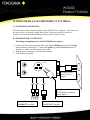
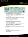
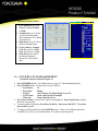
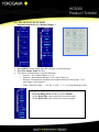
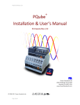
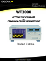
WT3000
Product Tutorial
WT3000
SETTING THE STANDARD
for
PRECISION POWER MEASUREMENT
Product Tutorial
1
WT3000
Product Tutorial
2
WT3000
Product Tutorial
WT3000 PRODUCT TUTORIAL
Table of Contents:
A.) Overview & Objectives ………………………………………
B.) Power Meter Connections ……………………………………
C.) Basic Setup for Power Measurement
Initialize Settings …………………………………………..
Setting Wiring ……………………………………………..
Setting Ranges ……………………………………………..
Setting Numeric Display Items ……………………………
Setting Crest Factor ………………………………………..
Setting Update Rate ………………………………………..
Page Function ……………………………………………..
Wave Display .…………………………………… ………..
Other Type of Displays …………………………………….
Bar Display …………………………………………..
Trend Display ……………………………………….
Vector Display ………………………………………..
Split Display …………………………………………..
5
5
6
6
7
8
8
9
9
9
10
10
10
11
11
D.) Harmonic Measurements
Single & Dual List Display ………………………………….. 12
Basic Numeric Display ………………………………………. 12
Bar Graph & Vector Display ……………………………….. 13
Selecting PLL Source ……………………………………….. 13
Selecting Harmonic Order ………………………………….. 13
Selecting THD Formula ……………………………………… 13
Frequency Band ………………………………………………. 14
E.) Cycle-by-Cycle Measurements
Set up and Applications ………………………………….…. 14
F.) Integrator Function
Integrator Modes & Measurement Functions ……………. 15
Normal Mode ……………………………………………….. 15
3
WT3000
Product Tutorial
G.) User Defined Functions
Set up and Applications ……………………………………
16
H.) Saving Data
Saving Data to Memory ……………………………………. 16
Recalling Stored Data ………………………………………. 16
J.) D-A Output Function …………………………………………… 17
4
WT3000
Product Tutorial
WT3000 POWER ANALYZER PRODUCT TUTORIAL
A.) OVERVIEW & OBJECTIVES
The following is a basic demo procedure for the WT3000 Power Analyzer. This demo uses
the power meter’s own power supply for the load. The demo can easily be done in a
conference room or lab without having to hook up to the customer’s load.
B.) POWER METER CONNECTION
Measuring consumption power of the WT3000 Power analyzer
1. Connect the Power Meter using the load cord. Plug the Banana plugs into the Voltage
input terminals of Element # 1. Connect the Spade lugs to the Current terminals of
element # 1. Make sure all connections are tight.
2. Plug the power meter power cord into the load cord.
3. Turn on the power meter.
15A
OUTLET
15A
Connect to 120 V
60 Hz Power
Source
A
H
Connect Spade Lugs to
CURRENT Terminals
L
Plug Power Cord from
WT3000 Power Analyzer
into Load box.
Connect Banana Plug to
VOLTAGE Terminals
5
WT3000
Product Tutorial
C.) BASIC SETUP FOR POWER MEASUREMENT
INITIALIZE SETTINGS (Manual Section 3.13)
1.Before you start your demo, you may want to
Initialize the settings to make sure it was not
left in an unknown mode or some functions
left on that may interfere with your demo.
2.Press [MISC] button.
3. Press Initialize Settings Soft Key.
4. Press Left Arrow Key to select OK.
5. Press [SET] button.
SETTING WIRING (Manual Section 4.1)
1. Press the [WIRING] button.
2. Press the Wiring Setting Soft Key.
3. Press the Blue [SET] button. Press the Blue Down Arrow
key to highlight 3P 4W.
4. Press the Blue [SET] button to select the 3P 4W-wiring
configuration. Element lights 1,2 & 3 will turn ON.
5. Press [ESC] button to clear the menu.
6. NOTE for this Demo we will use the 3P-4W wiring even
though we are only using single phase on Element #1. This
will allow you to demo some of the other functions later on
in the demo.
6
WT3000
Product Tutorial
SETTING RANGES (Manual Section 4.3)
1. Press Voltage Up/Down arrow key to select Voltage ranges of
15/30/60/100/150/300/600/1000 Volts. For this demo set Voltage Range to 150 V.
2. Press Current Up/Down arrow key to select Current ranges of 500mA/1/2/5/10/20/30
Amps. For this demo use 500 mA or 1 A range.
3. External Current Sensor Range Setting: Press [EXT SENSOR] button.
4. Press Current Up/Down arrow key to select Sensor ranges of 50/100/200/mV
1/2/5/10 Volts.
5. Sensor Scaling: Press [SHIFT] [EXT SENSOR] button, Sensor Ratio.
6. Use the Cursor Arrow keys to set the numeric scaling factor in mV/A.
7. MODE Setting: Pressing the [MODE] button will change the Measuring Mode for
Voltage or Current. The Mode will be changed for each of the active measuring
elements. In this case with 3P-4W, Elements 1,2 & 3 will be changed. Element 4
will not be changed.
• RMS: True RMS Measurement
• MEAN: Rectified Mean scaled to RMS. 1.11 multiplier to.
• DC: Simple Average. Blocks AC.
• RMEAN: Rectified Mean value. Half cycle average.
8. For this demo, use RMS Mode.
7
WT3000
Product Tutorial
SETTING NUMERIC DISPLAY ITEMS (Manual Section 5.1)
1. Press [NUMERIC] display button. The default is 4 numeric items.
2. Press [FORM] button. This lets you select the number of Numeric Items to be
displayed. Press the Soft Keys to choose 4 items; 8 items; 16 items or all items.
3. Selecting Single List or Dual List displays the Harmonic Items.
4. When displaying Single List or Dual List, use the [PAGE] UP or DOWN buttons to
see all the Harmonic data.
5. For this demo set Numeric Form to 8 items. Press [ESC] to clear Numeric Form
menu.
6. There are three ways to select the Numeric Display items.
• Using the ITEM & ELEMENT function keys.
• Using the User-Defined function key [USER].
• Select From the [ITEM] menu.
7. Press the UP Cursor button to highlight measurement item Urms1.
8. Press [U/I/P] button to see how the measurement item is changed. Try the other Item
Function keys and the [ELEMENT] key.
9. Press [SHIFT] +[USER] key, USER SET. There are four User selectable items. To
change the item Press the Soft Key and select an item from the menu list. Use the
Cursor Arrow keys to highlight the item then Press [SET] to select.
10. Press [ITEM] button. First Press Item No. Soft Key. Use the Cursor Arrow keys to
highlight the Item Number to be changed.
11. Press Function Soft Key to display the complete Item List. Use the Cursor Arrow
keys to highlight the measurement item. Press [SET] to select the item.
12. Press [ESC] to clear menu.
SETTING CREST FACTOR (Manual Section 4.6)
1. Press [MISC] button.
2. Press Config Soft Key. Select CF3 or CF6 with bottom Soft Key.
3. NOTE: When selecting CF6, the Voltage and Current Ranges are one-half the
standard ranges at CF3.
8
WT3000
Product Tutorial
SETTING UPDATE RATE (Manual Section 4.10)
1. Press [UPDATE RATE] button.
2. Press Soft Keys to change Update Rate from 50 msec to 20 sec.
3. The highest measurement accuracy is achieved with update rates of 250, 500 msec, 1,
and 2 sec. The measurement values are determined by applying an Exponential
Average for Measuring Period along with a digital filtering technique. EAMP
displayed next to update rate time.
4. For update rates of 50, 100 msec, 5, 10 and 20 sec the measurement values are
determined by applying an Average for the Synchronous Source Period. ASSP
displayed next to the update rate time.
5. NOTE for Harmonics data to be displayed, the Update Rate must be set at 500 ms or
slower. For this demo, set Update Rate to 500 ms.
PAGE FUNCTION (Manual Section 5.1 Page 5-4)
1. Press [PAGE Down] key to select nine pages of different Display configurations.
2. Note the Default Display for the 3P 4W Wiring Configuration.
3. Use the DISPLAY ITEM & ELEMENT keys to set up the display items for each
page if you want something different than the default settings.
SETTING WAVE DISPLAY (Manual Section 6.1)
1. Press [WAVE] display button.
2. Press [ITEM] display button. Press Wave Display Soft Key. Use Cursor Arrow keys
to select the waveform for display. Highlight the Waveform Number and Press [SET].
The waveform will be displayed when the White Dot appears for the selected item.
3. For this demo select U1 and I1 for display.
4. Press [ESC] key to clear menu.
5. Press V Zoom & Position Soft Key. This lets you perform a Vertical Zoom or Vertical
Positioning of the selected waveform.
6. Press [FORM] display button. This lets you configure various waveform display
functions using the menu and Soft Keys.
• Format: Single; Dual; Triad; Quad
• Time/div
• Trigger: Auto/Normal; Source; Slope; Level
• Display Settings: Grid types; Scale Values; Labels. Note: Scale Value for both the
Wave and Trend displays is turned ON or OFF in this menu.
• Wave Mapping: Auto; Fixed; User
7. Press [ESC] key to clear the menu.
9
WT3000
Product Tutorial
SETTING OTHER TYPE OF DISPLAYS (Manual Section 3.15)
1. Press [OTHER] display button.
2. Using the Others Menu and Soft Keys you can select up to nine different display
configurations.
3. BAR DISPLAY: (Expansion Function Manual Section 7.9)
• Press Bar Soft Key.
• Press [FORM] button. Use the Soft Keys to select Form as Single; Dual; or Triad.
Select Dual or Triad for the demo. Use Soft key to select the Start and End Orders. For
the demo select Start Order at 0, and End Order at 100.
• Press [ITEM] button. By default Bar Item No. 1 should be Volts (U), Bar Item No. 2
Amps (I), and Bar Item No. 3 Watts (P) all for Element No 1. Use the Soft Keys to
change the Functions.
4. TREND DISPLAY: (User’s Manual Chapter 7)
• Press [OTHER] display button, and Trend Soft Key.
• Press [FORM] button. Use the Soft Keys to select Form as Single, Dual, Triad, or
Quad. Select Dual or Triad for this demo. Use Soft Key to select Time/Div.
• Press [ITEM] button. Press Trend Display Soft Key. Use UP Arrow Cursor Key to
highlight All OFF. Press [SET] button to select. Use Down Arrow Cursor Key and
Left/Right Cursor Keys to select items T1, T2, and maybe T3. Highlight the item and
Press [SET] button to select. Press [ESC] to clear menu.
• Press Trend Items Soft key. Press Trend Object Soft Key. Use the Up/Down Arrow
Cursor Key to display T1, T2 and T3. By default T1 should be Volts (U), T2 Amps (I),
and T3 Watts (P), all for Element No.1. When Order is ---, it is the Total RMS Value
for the Function selected. Press Order Soft Key. Use Up/Down Arrow Cursor Key to
change the order being trended. As an example you could trend the Total RMS current
and the Third Order current of a device over time. Press [ESC] to clear menu
• Press Trend Scale Soft Key. Press Trend Object Soft Key and Up/Down Arrow
Cursor Keys to select desired object number. Press Scaling Soft Key. This will toggle
between Auto and Manual scaling. Auto Scaling could be used for this demo.
Manual Scaling could be set as follows for this demo:
T1 Upper Scale 1.500E+02 Lower Scale 1.000E+02 (100-150)
T2 Upper Scale 1.000E+00 Lower Scale 0.000E+00 (0 – 1)
T3 Upper Scale 1.000E+02 Lower Scale 0.000E+00 (0 – 100)
•
Scale Value: Display Scale Values are turned ON or OFF under WAVE/Display
Settings.
•
Press [ESC] to clear menus.
10
WT3000
Product Tutorial
5. VECTOR DISPLAY: (Expansion Function Manual Section 7.10)
• TO DISPLAY THE VECTOR DIAGRAM WITH THIS DEMO MAKE SURE
WIRING IS SET TO 3P-4W AND UPDATE RATE IS 500ms OR SLOWER.
• Press [OTHER] button and Vector Soft Key.
• Press [FORM] button.
• Press Mag Soft Key. Press Mag Soft Key twice to highlight both U Mag and I Mag.
Press Left Arrow Cursor Key to highlight the most significant digit. Use UP Arrow
Cursor Key to increase mag to 2 or 3 for this demo.
• Press [ESC] to clear menu.
6.
•
•
•
•
•
SPLIT DISPLAYS (User Manual Sections 3.15, 5.1 and 6.1)
Press [OTHER] button.
Press the Soft Keys to select any of Six different Split Screen Displays.
Pressing [ITEM] in Split Screen mode will select the setup menu for top display
function, such as Numeric. Pressing [LOWER ITEM]; [SHIFT] + [ITEM], will select
the setup menu for the bottom display function such as Wave.
Pressing [FORM] button in split Screen mode will select the Form setup menu for the
top display. Pressing [LOWER FORM]; [SHIFT] + [FORM], will select the Form
setup menu for the bottom display.
Press [ESC] to clear menu.
11
WT3000
Product Tutorial
D.) HARMONIC MEASUREMENTS
•
•
•
1.)
•
•
•
•
•
•
•
•
•
•
•
•
•
•
•
Expansion Function Manual, Chapter 7 & 8
NOTE: UPDATE RATE MUST BE SET TO 500 msec OR SLOWER FOR
HARMONIC MEASUREMENT FUNCTION
If the Update Rate is set faster than 500 msec, the Harmonic Numeric display will
indicate - - - - - - - .
Harmonic measurements and Normal measurements are made simultaneously in the
WT3000. There is not a Harmonic Mode and Normal Mode selection like in other WT
and PZ Series Power Analyzers.
Harmonic Display: Expansion Function Manual, Section 7.1 – 7.4
Single List and Dual List Display
Press [NUMERIC] button for basic Numeric display.
Press [FORM] button then select Single List or Dual List Soft Key. Press [ESC] to
clear the Form menu. This is a quick and easy way to show all the harmonic data.
Press [PAGE Down] to view all the harmonic data.
Press Left Cursor Arrow button to highlight Page Scroll function for the data on left
hand side of the display. Now by Pressing [PAGE Down] the left hand column of data
will scroll through seven pages of data.
Press Right Cursor Arrow button to return to the List Page function.
Basic Numeric Display
Press [NUMERIC] button for basic Numeric display.
Press [FORM] button then select 4 Items, 8 Items, or 16 Items Numeric display.
Press [ESC] to clear form menu.
Press Up/Down Cursor Arrow button to highlight display position to change.
Press [ITEM] button. Press Function Soft Key. Use Cursor Arrow buttons to highlight
a measurement function such as Ithd. Press [SET] button.
To display an Item like third order current, Press [ITEM] button.
Press [U/I/P] button to display I.
Press Order Soft Key. Press Up Arrow Cursor button to select Order 3.
12
WT3000
Product Tutorial
•
•
•
•
•
•
•
•
•
•
Bar Graph & Vector Display
Press [OTHERS] button and Select type of Display such as Bar, Vector, or one of the
combination displays.
Select Bar. Press [FORM] button. From the menu select type of display such as Single,
Dual or Triad. Select number of Harmonic Orders to display by using the Start Order and
End Order. Use this as a “Zoom” function for the Bar Display.
Press [ITEM] button. From the menu select Function ( U, I, P, etc) to display as a Bar
Graph. Use the Bar Item No. to select where to display a selected Function.
Press [OTHERS] button and Select Vector.
Press [FORM] button. In this demo example the Object should be set to “Sigma A”,
Numeric ON.
Use the Mag function to expand the Vector display
IEC Harmonic Display: Expansion Function Manual Chapter 9
Press [OTHERS] button.
Press Next, display menu 2/3 and Select IEC Harmonics. The WT3000 is now set to
comply with the IEC Harmonic Measurement functions.
2.) Harmonic Set: Expansion Function Manual, Sections 7.5 - 7.8
•
•
•
•
•
•
•
•
•
•
•
•
•
•
•
•
•
Selecting PLL Source
Press [HRM SET] button. Press PLL Source Down Exec Soft Key. The PLL source is
displayed on the upper right corner of the screen.
Select a PLL source that has an input signal with little distortion.
For this demo it is best to select U1 as the PLL source.
For Power Supply applications, select a Voltage input for the PLL Source
For a PWM Motor drive applications, select a Current input for the PLL Source.
Selecting Harmonic Orders
Press [HRM SET] button.
Press Min Order Soft Key. Pressing this key toggles between 0 (DC), and 1
(Fundamental).
Press the Up/Down Cursor Arrow buttons to change the Max Order.
The Max Order sets the number of Harmonic Orders over which to calculate the THD.
As an example a specification may call for calculating THD over 50 Orders.
Selecting THD Formula
Press [HRM SET] button.
Press THD Formula Soft Key.
UL & CSA applications typically use 1/Total as the mathematical formula. This is using
the Total RMS value of the harmonic item such as Voltage, or Current, or others.
IEC applications use 1/Fundamental as the mathematical formula. This is the
Fundamental value of the harmonic item. This calculation can result in a higher THD
calculated number, and can even exceed 100% on highly distorted waveforms.
13
WT3000
Product Tutorial
•
Selecting Frequency Band
•
•
•
•
•
•
Press [HRM SET] button
Select Freq Band Normal
or Wide.
Normal Band covers 10 Hz
to 440 Hz Fundamentals
and simultaneous True RMS
measurements.
Wide Band covers 0.1 Hz to
2600 Hz Fundamentals
Display Irms1 in Normal
Band then switch to Wide
Band and observe readings.
Wide Band is the sum of
the Integer Harmonic
Orders up to 100 Orders
Max.
G.) CYCLE-BY-CYCLE MEASUREMENT
Expansion Function Manual Chapter 13
•
•
•
•
•
Press [OTHERS] button. Press Next and go to page 2/3. Press Cycle-by-Cycle
Press [FORM] button. For this demo set up as follows:
o Sync Source
U1
o Sync Slope
Rising
o Trigger
Auto; Source U1; Slope Rising; Level 1%
o Cycle Count
Some value 20-60 for example
o Time Out
Some value like 10 sec
Press Start Soft Key. Data will be acquired and displayed. Press Page Down to display
data in 20 cycle groups.
To make another acquisition, Press Reset Soft Key, Left Arrow OK, SET. Then Press
Start Soft Key again.
To change the Measured Items, Press [ITEM] button. There are 10 different functions
available for Cycle-by-Cycle measurement. Five Items can be displayed.
14
WT3000
Product Tutorial
E.) INTEGRATOR FUNCTIONS
User’s Manual Section 5.11
INTEGRATOR MODES & MEASUREMENT FUNCTIONS
• Set Numeric Display as shown below.
WP = Watt Hours
q = Ampere Hours
WS = Volt-Amp Hours
WQ = VAR Hours
Time = Integration Run Time
•
•
•
•
Press [INTG] button.
Press Start Soft Key to start Integration function. Once Integration is started, you cannot
change any of the settings. Try changing Range or any of the other functions
Press Stop to stop Integration function. Note Timer stops as Integration functions.
Press Start again and note the Timer starts again as well as Integration functions. This is
more like a Pause condition. Settings Cannot be changed.
To Quit or End Integration function, Press Stop then Press Reset. This stops the
Timer, and now settings can be changed. Quit Integration before continuing.
15
WT3000
Product Tutorial
F.) USER DEFINED FUNCTIONS
User’s Manual Section 5.4
•
•
•
•
•
•
The WT3000 includes a powerful User Defined Math Function as standard. Twenty
Math Functions can be assigned for special analysis and computation.
Press [MEASURE] button. Select User Defined Function.
Select User Defined F1 – F5. Use the Up/Down Arrow buttons to highlight the
Expression line for Function 1. Press SET to display the keyboard and the available
Math functions.
The Default UMN(E1) is a very common function for Transformer Testing and Motor
Drive Testing.
Transformer Testing requires the Simultaneous display of True RMS Voltage and MEAN
Voltage. If the values are different, it will give an indication of distortion.
The Mean Voltage function is used on Variable Speed Motor Drives as a way to measure
the Fundamental Voltage of the drive voltage.
G.) STORE FUNCTION
User’s Manual Chapter 8
•
•
•
•
•
•
•
•
•
Press [SHIFT] [STORE] (Store Set).
Set Mode to Store; Store to Memory.
Press Store Setting Soft Key and set as follows:
o Mode
Manual for the demo exercise
Some number you like for amount to be stored
o Count
o Interval Setting With All Zeros, the store Interval will be at the selected Update
Rate. You can select some other time interval
Numeric for this demo
o Store Item
o List Item
Select a few items like U, I, P, PF, FREQ for Element 1.
Press ESC to clear all Menus.
Press [STORE] button to start. Initialize memory if so prompted. Press [STORE]
button again to start storing data.
Press [SHIFT] [STORE] buttons and select Mode Recall.
Scroll Recall No. to view stored data. Make sure Display matches the Stored Items
selected.
Stored data can be saved to Memory Card, USB Memory, or transferred to PC in CSV
file format.
Store function provides a means for Data Acquisition for fast short time periods to long
term unattended operation.
16
WT3000
Product Tutorial
G.) D/A OUTPUT FUNCTION
Expansion Function User’s Manual Chapter 3
•
•
•
Press [MISC] button. Press Next 1/2 to display second menu page.
Press D/A Output Items Soft Key.
From the D/A Output Menu, set up the following
o Item No.: D/A Output Channel, 1 to 20
o Function: Measurement function, Volts, Amps, Watts, etc.
o Element: Element from which the measurement function is being made, 1 to 4,
plus Sigma A, and Sigma B.
o Order: Harmonic Order. --- is Total. 0 is DC. 1, 2, 3, etc is the Harmonic Order.
Setting the D/A Zoom Function
• Press the Range Mode Soft Key to select Manual.
• Set the Rated Max value to that of the measured signal.
• Set the Rated Min value to that of the measured signal.
17