1
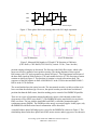
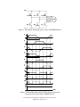
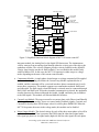
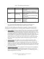
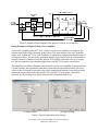
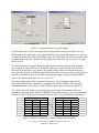
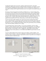
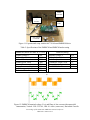
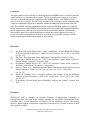
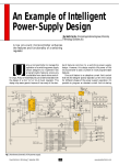
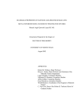
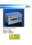
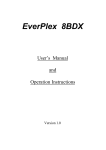
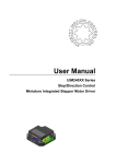
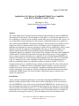
Paper 175, ENG 105
Application of a Software Configurable Digital Servo Amplifier
to an Electric Machine Control Course
Shiyoung Lee, Ph.D.
Pennsylvania State University Berks Campus
[email protected]
Abstract
The various applications of the three-phase permanent magnet brushless dc motor (PMBDCM)
in the industry are increasing. The main purpose of this paper is to describe the application of a
new technology to academic electric machine control and/or power electronics drive courses. An
easy method for the implementation of a fully software-configurable digital servo amplifier to
drive a three-phase PMBDCM is presented in this paper. This developed servo amplifier may be
suitable for an electric machine control course. The change of drive configuration requires
additional development time and cost, especially in control software modification, which, in turn,
depends on the specific application. The highlight of the paper is the GUI (Graphical User
Interface)-based control software (Pro-Motion) setup for implementation of a softwareconfigurable digital servo amplifier. The principle of the operation of the three-phase PMBDCM
is discussed first, and then the requirement to develop three different types of servo amplifiersuch as velocity, position, and torque servo amplifiers-to drive the three-phase PMBDCM, are
explained. The details of a selected motor control integrated circuit (IC), MC73110 from PMD
Corp., are introduced. The various capabilities of the IC that make fast implementation of a
software-configurable digital servo amplifier possible are discussed. The MC73110 IC is
incorporated into the servo amplifier design, resulting in an increased ease of use with software
configuration. To validate the software-configurable digital controller, a step-by-step design
example to develop a velocity servo amplifier is completely explained and some of the test
results are discussed. As a conclusion, suitable teaching topics based on the proposed softwareconfigurable PMBDCM drive for electric machine control and/or power electronics drive
courses are summarized.
Introduction
Today, numerous industrial applications are increasingly adopting the PMBDCM due to its
inherent variable speed drive aspect. Since the electronic commutation circuit is necessary to
drive the PMBDCM, it may not be easy to implement the PMBDCM drive. In most cases, it is
time-consuming and expensive to build instructional components for motor drives into existing
electric machine control related courses [1, 5, 6]. The implementation of hardware and software
usually takes time to complete. But many different types of development kits are available off
the shelf for various types of motors [2]. These development kits are aimed mainly at the
Proceedings of The 2008 IAJC-IJME International Conference
ISBN 978-1-60643-379-9
industrial sector, but they look attractive for educational application because they provide not
only hardware platforms, but also dedicated setup software.
The MC73110-based development kit may be suitable for the fast and easy development of the
PMBDCM drive instructional components. This paper proposes the MC73110 motor control ICbased developer’s kit for this purpose. This kit was chosen for the easy and cost-effective
implementation of the instructional component of the PMBDCM drive in the electric machine
control course. The PMBDCM drive is increasingly popular in the industry sector, but it has not
been integrated into an academic curriculum. Consequently, it is the logical choice for
incorporation into an academic course that will prepare students for industry. The development
kit provides a hardware platform that contains all necessary analog and digital circuits on one
PCB and user-friendly GUI-based configuration software. The two-volume user manual is also a
good resource to use in the design of any size and type of PMBDCM drive.
It is suitable and timely to investigate the incorporation of the PMBDCM drive into the electric
machine control course. The design of the PMBDCM drive has two major tasks, one in hardware
and another in software design. To accomplish both design tasks, one should understand its
principle of operation. The hardware design could be classified as, but not limited to, power
circuitry that includes a power switching circuit, analog and/or digital sensor circuits, and
controller circuitry. The development of application-specific software for a motor drive is not
always an easy task. Fortunately, the MC73110-based development kit provides user-friendly
drive configuration software for easy setup of the desired type of the PMBDCM drive.
In this paper, the technical concepts of the PMBDCM and its drive are explained first to provide
a fundamental background of the overall drive system suitable to the conventional electric
machine control and/or power electronics courses. Second, the characteristics of the MC73110
motor control IC will be explained.
Principle of Operation of the PMBDCM Drive
The PMBDCM is an electronically commutating permanent magnet motor. The applications of
this motor are growing. Because of its inherent variable-speed drive nature, it is widely used in
white goods, automobile, and machine-building industries. The commutation circuit for the
three-phase PMBDCM can be implemented with discrete components or dedicated control IC.
The design with discrete components provides many insights on the commutation circuit for
students; at the same time, it requires lots of time and effort to build the hardware and to
troubleshoot. The dedicated IC approach looks promising because little or no additional circuitry
is required. Some manufacturers even offer dedicated setup software to use their IC.
The mechanical structure of the PMBDCM is the reverse of the conventional permanent magnet
brushed dc motor (PMDCM); the rotor contains permanent magnets, and the motor windings are
mounted on the stator [7]. The PMBDCM does not have brushes that are required for
commutation of the PMDCM. Therefore, a maintenance-free motor drive system is possible with
the PMBDCM.
To drive the PMBDCM, an electronic commutation circuit is required. This paper is concerned
only with the position sensor-based commutation; therefore, the two common
Proceedings of The 2008 IAJC-IJME International Conference
ISBN 978-1-60643-379-9
Hall A
Hall B
Hall C
0
180
360
540 Electrical Degree
Figure 1. Three-phase Hall sensor timing chart with 120° angle separation
(a) CW direction
(b) CCW direction
Figure 2. Measured Hall signals in CW and CCW direction at 1500r/min
(CH1: Hall A, CH2: Hall B, CH3: Hall C)(Vertical: 2V/div, Time: 5ms/div)
position-sensing techniques are discussed. The first one is the Hall effect sensor, which is the
most cost-effective method of rotor position sensing. The timing diagrams of three typical
Hall sensors with 120o angle separation are shown in Figure 1. The experimental waveforms of
the three Hall signals in both clockwise (CW) and counterclockwise (CCW) directions of motor
rotation are shown in Figure 2. The direction of rotation is viewed at the motor shaft. The
sequences of the Hall signals are Hall A-Hall B-Hall C in the CW direction and Hall B-Hall CHall A in the CCW direction.
The second method uses the optical encoder. The incremental encoder is widely used due to its
lower cost than the absolute type. However, the optical encoder provides better resolution of
position data than the Hall sensor, therefore making precise control of the PMBDCM possible.
There are two types of permanent magnet brushless dc motors, which depend on their backelectromotive force (EMF) waveforms [7]. The PMBDCM has the trapezoidal (six-step) backEMF waveform. The one with the sinusoidal back-EMF is called the permanent magnet
synchronous motor (PMSM). The PMSM provides nearly zero torque ripples. In this paper, only
the PMBDCM with Hall sensor-based commutation will be discussed.
A simplified three-phase full-bridge power circuit for the PMBDCM is shown in Figure 3. The
relationships between the three-phase back-EMF, motor current, and air-gap power are shown in
Proceedings of The 2008 IAJC-IJME International Conference
ISBN 978-1-60643-379-9
Figure 3. Three-phase full-bridge power circuit for PMBDCM drive
Figure 4. Relationship between back-EMF, motor current, and
air-gap power for three-phase PMBDCM drive
Proceedings of The 2008 IAJC-IJME International Conference
ISBN 978-1-60643-379-9
Figure 4 [7]. The trapezoidal back-EMF (ea, b, and c) has a constant magnitude of Ep during 120
electrical degrees in both the positive and negative half-cycle. The air-gap power (Pa) and the
electromagnetic torque are both continuous when applying motor current (ia, b, and c ) during the
same period in both half-cycles as shown in Figure 4. The Hall signals provide position
information of the flat-top portions of the back-EMF in both half-cycles. Based on the position
information, it can be seen that the pulse width modulated motor voltage; hence, the motor
current is applied to generate the motor torque.
Introduction of the MC73110 Motor Control IC
For the fast-changing motor drive technology in industry, the provision of a new motor control
IC was beneficial in developing a digital servo controller without time-consuming effort spent on
control software development. The MC73110 motor control IC has developed into an advanced
single-chip, single-axis device that can be used to implement an intelligent three-phase
PMBDCM controller based on FPGA and ASIC technologies [3, 4]. It is packaged in a 64-pin
thin quad flat pack (TQFP) measuring 12 mm by 12 mm and operates on 3.3V. It can be operated
in internal velocity profile mode, velocity mode with an external analog, digital velocity
command signal, or torque mode with an external torque command signal. It also can be
operated as a standalone controller using pre-programmed parameters stored onto chip flash
memory or through the RS-232 serial port using the Pro-Motion GUI setup software. The
simplified functional block diagram of the MC73110 is shown in Figure 5.
The various functions useful for the development of the PMBDCM drive are embedded in the
MC73110 IC. These functions include the three-phase PWM generation for three-phase fullbridge power circuit and three-signal PWM for single switch per phase power circuit
configuration, Hall- or quadrature encoder-based commutation, digital current and velocity
loops, profile generation, emergency stop, analog velocity command, and RS-232 serial
communication port, for example. Both the six-step and sinusoidal commutation methods are
possible with this IC. But a quadrature encoder is required in addition to the Hall-effect sensors
to implement the sinusoidal drive.
The details of the six main functional modules in the MC73110 IC are listed below [3]:
•
Profile Generator Module: This module generates a velocity- and acceleration-bounded
profile by using the serial port commands. The instantaneous desired velocity value is put
out to either the velocity integrator or the velocity loop module. A host processor
(microprocessor or personal computer) is needed to utilize this module.
•
Velocity Integrator Module: A desired velocity value from the profile generator module,
or an external analog signal (AnalogCmd), or a synchronous serial digital 16-bit word
data stream, serial peripheral interface (SPI) bus, will be applied to this module. This
value integrates into an instantaneous desired position, which is compared with the actual
position from the encoder, to develop either desired velocity or torque.
•
Velocity Loop Module: Next, a desired velocity command emerges into this module. The
velocity command with the current instantaneous velocity of the motor axis will be
combined to determine a desired torque or voltage command in this module. The desired
velocity command will be generated from the profile generator module, the velocity
Proceedings of The 2008 IAJC-IJME International Conference
ISBN 978-1-60643-379-9
PWM Output Disable
A/D
10-bit
Current
Command
16-bit
Hall
Sensors
6-Signal PWM
Output with
Shoot-through Delay
PhaseC
CurrentA
CurrentB
Digital Current
Loop Module
PhaseB
SCI
3-Signal PWM
50/50 Output
Motor Output Module
(3- or 6-signal output)
PhaseB
SrlEnable
SrlXmt
SrlRcv
Flash User
Configuration
Storage
PhaseA
Command
Processor
PhaseA
Serial EEPROM
I2CData
I2CClk
Amplifier Disable
Commutation
Module
Reset
Motor
Command
Estop
Velocity
A/D
10-bit
QuadA
QuadB
Index
Position Feedback
and
Commutation Angle
AnalogCmd
A/D
10-bit
DigitalCmdData
DigitalCmdClk
SPI
16-bit
Velocity
Loop
Velocity
Integrator
Velocity
Command
16-bit
Profile
Generator
Figure 5. Simplified functional block diagram of MC73110 motor control IC
integrator module, the AnalogCmd, or the digital SPI data stream. The instantaneous
velocity emerges from an analog signal through either the velocity pin of the chip or the
quadrature encoder. The velocity estimator provides velocity feedback to the digital PI
velocity loop from the encoder or Hall feedback. Users can disable this module easily
with Pro-Motion GUI. In this case, the MC73110 operates in either torque or voltage
mode, depending on the state of the current control module.
•
Commutator Module: A single-phase desired torque or voltage command will be applied
to this module depending on whether the Current Loop Module explained below is
enabled, and this command will be vectorized into three-phase commands-one for each
motor phase connection. This module supports two commutation methods: Hall-based
and sinusoidal. The Hall signals, when Hall-based is selected, must be connected through
Hall1, Hall2 and Hall3 pins. When the sinusoidal commutation is selected, the quadrature
encoder data must be connected through the QuadA, QuadB, and Index pins in addition
to the Hall signals. This module will remain enabled at all times.
•
Current Loop Module: The target current for two motor phase coils (PhaseA and PhaseB)
will be applied to this module. It uses two sensed analog feedback signals, CurrentA and
CurrentB, to develop three PWM output values for a three-phase PMBDCM. When the
MC73110 operates the motor in the voltage mode, this module can be disabled.
•
Motor Output Module: The desired voltage for each of the three motor phase coils will be
applied to this module. Then it generates the PWM signal in either three-signal mode
(one signal per phase) or six-signal mode (high-side and low-side signals for each phase
Proceedings of The 2008 IAJC-IJME International Conference
ISBN 978-1-60643-379-9
Table 1. Three different operation modes
Operation Mode
Torque
Modules Encoded
Current Loop
Velocity
Current Loop,
Velocity Loop
Intelligent Motion
Controller
Current Loop,
Velocity Integrator,
Profile Generator
Minimal Connections
Hall A, B, and C
CurrentA/B
QuadA/B (sinusoidal commutation only)
DigitalCmdClk/Data or AnalogCmd
Hall A, B, and C
CurrentA/B
QuadA/B (sinusoidal commutation only)
or Tachometer
DigitalCmdClk/Data or AnalogCmd
Hall A, B, and C
CurrentA/B
QuadA/B
SrlXmt/Rcv
leg). The generated PWM output signals are symmetric waveforms; they are
synchronized to the master PWM output switching frequency at 20kHz.
The MC73110 can be configured as different types of amplifiers, as summarized in Table 1.
Most applications may fall under one of the three standard configurations explained below:
•
Torque Amplifier: The torque command will be either an analog signal or an SPI digital
data stream. The typical target application of this mode may be the position servo with
external position loop and position feedback. The position feedback signal can be analog
with analog feedback devices or digital with a microprocessor. One example of the
position feedback is the potentiometer, which provides continuously varying voltage that
is proportional to the rotor position. The torque amplifier can be a standalone or can
employ a host processor. The MC73110 motor control IC has a 20 kHz digital current
loop. The two motor current feedback signals (CurrentA/B) are required to close the
current loop.
•
Velocity Amplifier: This amplifier can be another standalone application with the
velocity loop enabled. The MC73110 has an internal digital velocity loop with a rate
frequency of 10 kHz. The velocity command signal will be the same as for the torque
amplifier; the difference is that the command signal represents velocity rather than torque
in the torque amplifier. The Hall signal or the encoder or the tachogenerator can be used
as the velocity feedback.
•
Intelligent Motion Controller: This configuration needs a host processor or computer to
generate a command signal through the profile generator. In this case the MC73110
works as an intelligent programmable motion controller. The command signal will be
applied through the RS-232 serial port.
Proceedings of The 2008 IAJC-IJME International Conference
ISBN 978-1-60643-379-9
Figure 6. Simplified block diagram of the proposed velocity servo amplifier
Design Example of a Digital Velocity Servo Amplifier
To prove the capability of the MC73110, a digital velocity servo amplifier was designed. The
experimental results will be discussed in this section. The major benefit of the servo amplifier
design, used with the MC73110, is the flexibility of control loop configurations and the setup of
its parameter values. The previously mentioned amplifier types can be software configurable by
using the interactive Windows-based Pro-Motion GUI software. Since this software is royaltyfree, the development of any industrial applications with MC73110 can be cost-effective.
The simplified overall block diagram of the proposed velocity servo amplifier is shown in Figure
6. In this example, the explanation of hardware connections will be omitted. Rather, the focus
will be on the verification of software setup. After completion of hardware setup and successful
connection between the host PC and the MC73110, the MC73110 developer’s kit will be
activated, first by invoking Axis Setup Wizard on the Pro-Motion window [4].
(a) Signal output
(b) Signal sensing
Figure 7. Signal output and sensing settings
Proceedings of The 2008 IAJC-IJME International Conference
ISBN 978-1-60643-379-9
(a) Commutation
(b) Velocity PI
Figure 8. Commutation and velocity PI settings
The first page of the wizard is the signal output setting window, as shown in Figure 7(a). The
PWM output mode can be either three-signal mode for a three-phase half-bridge power circuit or
six-signal mode for a three-phase full-bridge circuit. The PWM dead time will activate only with
six-signal mode to prevent a possible shoot-through fault in the phase leg. It can be set to range
from 0 to 12µs.
The PWM limit allows enough off-time for charging the bootstrap capacitor in the bootstrap
power supply for a high-side switch. The PWM output logic can be checked for the polarity
inversion of the gate drive logic signals. The signal-sensing window provides the necessary
inversion of the polarity of feedback signals from Hall sensors and/or an encoder. During normal
operation, black dots in white circles blink, indicating the change of signals through feedback
sensors. The default signal sense is set to “active low.”
The commutation setup window is shown in Figure 8(a). The commutation mode can be
trapezoidal with Hall sensor feedback or sinusoidal with encoder feedback. The sinusoidal
commutation mode may be effective with a PMSM to generate near-zero torque ripples [7].
The “Open loop start!” button can be used to check the phasing of Hall signals and motor
windings in open loop mode. When the PMBDCM commutates properly, it gives smooth motion
in both CW and CCW directions of rotation. This function is very useful during initial setup of
1
2
3
4
5
6
Motor Phase Winding
PH A
PH B
PH C
A
B
C
A
C
B
B
A
C
B
C
A
C
A
B
C
B
A
Hall Effect Sensor
S1
S2
S3
H1
H2
H3
H1
H3
H2
H2
H1
H3
H2
H3
H1
H3
H1
H2
H3
H2
H1
Figure 9. Possible combinations of motor windings and Hall signals
Proceedings of The 2008 IAJC-IJME International Conference
ISBN 978-1-60643-379-9
1
2
3
4
5
6
matching Hall signals with relevant motor windings. Without this function, all possible
combinations of Hall signals and motor windings should be checked for correct phase matching.
The 36 possible combinations are shown in Figure 9. The one combination of each group of
motor phase windings and Hall signals should provide an even response for the bipolar command
signal.
The setup of velocity loop parameters depends on feedback devices, as shown in Figure 8(b).
The allowable velocity feedback sources are analog (tachogenerator), encoder, and Hall signals.
The values of PI parameters will be selected by trial and error through the command window.
The GetLoopError instruction gives the value of the velocity error. The optimum values of PI
parameters can be found by observing the minimal change in the returning velocity error values
in either positive or negative polarity. Since the MC73110 does not have the capability of
graphical representation of error values, this procedure may be tedious and time-consuming.
The same procedure could be applied to the current loop to find out optimum PI parameter
values, as shown in Figure 10. The motion window provides for the selection of servo loops and
motor dynamics. For the standalone application, such as the velocity servo amplifier example in
this paper, the velocity command source should be analog. The typical analog velocity command
value will be the industry standard ±10V dc voltage.
The experimental setup is shown in Figure 11. The velocity command is ±10V dc voltage
(labeled as Analog Command in front). The communication between the MC73110 and the ProMotion software is performed with an RS-232 serial cable. The PMBDCM under testing is the
Maxon EC-Max 30, order number 272769. A PMDCM is connected back to back with the
PMBDCM to form a motor-generator set. The PMDCM and PMBDCM specifications are listed
in Table 2.
The pulse width modulated motor terminal voltage between Phase A and B and Phase A line
current is shown in Figure 12. Since the commutation is Hall-based trapezoidal (six-step), the
measured current waveform resembles the trapezoidal waveform except in the zero-crossing area
and top flat portions in both half-cycles.
(a) Current PI
(b) Motion
Figure 10. Current PI and motion settings
Proceedings of The 2008 IAJC-IJME International Conference
ISBN 978-1-60643-379-9
PMDC
Generator
PMBDCM
+
Encoder
RS-232
Cable
±10V Analog
Command
Figure 11. Experimental setup with the MC73110-based PMBDCM drive
Table 2. Specifications of the PMBDCM and PMDCM under testing
PMBDCM (Maxon EC-Max 30, 272769)
Nominal Voltage, V
No Load Speed, r/min
No Load Current, mA
Nominal Speed, r/min
Nominal Current. mA
Torque Constant, mNm/A
Speed Constant, r/min/V
Mechanical Time Constant, ms
36.0
9160
73.20
7080
97.60
36.8
259
6.98
PMDCM (Moog)
Nominal Voltage, V
No Load Speed, r/min
Peak Torque, oz-in
Continuous Torque, oz-in
Torque Sensitivity, oz-in/A
Back-EMF, V/rad/s
26.0
10346
50
7.5
3.42
0.024
Figure 12. PMBDCM terminal voltage (VAB) and Phase A line current with trapezoidal
commutation, Vertical: CH1: 25V/div, CH4: 0.1A/div (center zero), Horizontal: 5ms/div
Proceedings of The 2008 IAJC-IJME International Conference
ISBN 978-1-60643-379-9
Teaching Components with the Proposed Servo Amplifier for the PMBDCM
The proposed digital servo amplifier based on a highly integrated MC73110 motor control IC
provides various teaching components to enhance the electric machine control and/or power
electronics drive courses. Possible teaching topics and their brief explanations are listed below:
•
Power Circuit and Gate Drive Circuit: The MC73110 IC supports not only conventional
three-phase full-bridge power circuits with six power switching devices but also threephase half-bridge power circuits with three power switching devices. Further, a threephase half-bridge power circuit can be applied to the switched reluctance motor (SRM)
drive with Hall position feedback sensors. In this case, the motor winding of SRM or
PMBDCM is preferably Y-connection with the center point accessible. Usually, the halfwave power circuit produces less output power than the full-wave power circuit [7].
The gate drive for the high-side switching devices requires isolation when an N-type
metal-oxide field effect transistor (MOSFET) device is used. By using a P-type MOSFET
device, the free of isolation of gate drive is possible. The various aspects of the types of
power switching devices and gate drive selection will be attractive topics to be discussed
in detail. The method of the heat-sinking of power switching devices should be addressed
with power circuit topologies.
•
PWM Method: The various PWM strategies to generate PWM gate signals to drive threephase power circuits can be introduced. Among them, the symmetric three-phase PWM
method is implemented in the MC73110 IC.
•
Back-EMF Types and Commutation Method: Two types of commutation strategy can be
introduced: six-step (trapezoidal) and sinusoidal. Six-step commutation can be
implemented with Hall position feedback sensors only. It is suitable to the PMBDCM
that has trapezoidal back-EMF waveform. On the other hand, the sinusoidal commutation
needs a quadrature encoder in addition to Hall position sensors. This method is applied to
the PMSM with sinusoidal back-EMF waveform. But the different effects can be
investigated when both commutation methods are applied to the PMBDCM.
•
Control Loop Closure: The velocity and torque loops are embedded on the MC73110.
The basic open-loop and closed-loop control systems can be demonstrated to the class.
The observation of effects when closing either or both control loops will be an interesting
task for students. Also, the effects of the various proportional (P) and integral (I) gain
values in the control loop can be observed through experiment. Because of the lack of
graphical representation capability in Pro-Motion setup software, the continuous
monitoring of various control variables is not possible. Instead, as an example, the
GetLoopError instruction makes monitoring of discrete velocity and torque loop error
values possible. To implement a position servo controller, a position loop can be added
externally to the velocity command. It can be realized with few external analog
components or with a tiny microcontroller. The velocity loop must be disabled to
accommodate an external position loop.
Proceedings of The 2008 IAJC-IJME International Conference
ISBN 978-1-60643-379-9
•
RS-232 Serial Communication: Serial communication is an industry standard means of
transmitting and receiving data between a computer and a peripheral device. It is one of
the most popular communication methods because the RS-232 serial port is installed on
most computers. It should be noted that the MC73110-based servo amplifier could be
configured as a standalone unit. In this case, the necessary control parameters should be
downloaded into an on-chip flash memory in the MC73110 IC.
•
Current Sensing Circuit: To close the current loop, the MC73110 requires two motor
phase currents’ (phases A and B) information. The phase C current is generated internally
by combining those currents. Various current sensing techniques can be discussed: the
passive way with a current sensor resistor and Hall sensor based current sensing IC. The
different implementation methods of the analog signal processing circuit need to be
discussed along with the current sensing circuitry. The analog signal processing circuit
for the current sensor varies widely depending on the current sensing technique.
The following topics are relevant to broaden the coverage further:
•
IC Packaging Type: Various package types of modern surface mount devices (SMDs) can
be introduced to the class. The MC73110 IC is built on a 64-pin TQFP. Some of the IC
package types that may be found on the MC73110 development board are small-outline
package (SOP), small-outline integrated circuit (SOIC), thin shrink small-outline package
(TSSOP), and discrete packaging (D2PAK) for power switching devices.
•
Protection of the Dc Voltage Polarity Reversal: The required voltage type for the
MC73110 development kit is dc. The addition of the protection circuit against the dc
polarity reversal is a must for practical application.
•
Regenerative Braking Circuit: A regenerative braking circuit should be included for the
four-quadrant operation of the servo amplifier to dissipate the regenerative energy flows
back to the bus when the PMBDCM operates in regeneration mode. It can be easily
implemented with a comparator with the bus voltage sensing circuit, a power-switching
device (N-type MOSFET), and a power resistor to dissipate the regenerated energy.
•
Level Shift Circuit: The MC73110 is powered with 3.3V. Therefore, the various higher
input signal levels, such as 5V and 10V, should be converted into 3.3V. A level shift
circuit with an operational amplifier can be addressed as an example of a real-world
application of an operational amplifier.
•
Electromagnetic Interference (EMI) or Radio Frequency Interference (RFI): The
EMI/RFI issue directly relates to the clock and PWM frequency in the proposed servo
amplifier. The proper management of the printed circuit board (PCB) design is required
to minimize the EMI/RFI effect. It is important to address this issue and examine the
PCB design. The grounding technique, the use of power and ground planes in multilayer
PCB design, and the elimination of ground loop may be worthy topics for discussion.
Proceedings of The 2008 IAJC-IJME International Conference
ISBN 978-1-60643-379-9
Conclusion
This paper addresses the feasibility of employing the digital PMBDCM drive in electric machine
control and/or power electronics drive courses. The low cost and time-saving way to develop a
software-configurable digital servo amplifier for the PMBDCM drive was confirmed with a
velocity servo drive example. The MC73110 developer’s kit is extremely useful in implementing
a software-configurable digital servo amplifier without spending high development costs and
time. The attainable teaching components with the proposed PMBDCM digital servo amplifier
are the characteristics of the PMBDCM, the distinction between sinusoidal and trapezoidal drive,
and the uniqueness of Hall-sensor and encoder-based commutation methods. The difference
between three-phase full- and half-bridge power circuits, the assorted gate drive circuitry, a
variety of current sensing methods, the aspects of velocity and current PI controllers, and the
various analog signal conditioning methods are also suitable.
References
[1]
[2]
[3]
[4]
[5]
[6]
[7]
Rui Hong Chu, Dylan Dah-Chuan Lu, and S. Sathiakumar, “Project-Based Lab Teaching
for Power Electronics and Drives,” IEEE Trans. on Education, Vol. 51, No. 1, Feb. 2008,
pp. 108–113.
Jon Titus, “Kits Jump Start: Motor Applications,” Design News, August 13, 2007.
Performance Motion Devices, Inc., “MC73110 Advanced 3-phase Motor Control IC
Product Manual,” Revision 1.4, October 2004.
Performance Motion Devices, Inc., “MC73110 Advanced 3-phase Motor Control IC
Developer’s Kit Manual,” Revision 1.4, August 2005.
Rovert S. Balog et al., “Modern Laboratory-Based Education for Power Electronics and
Electric Machines,” IEEE Trans. on Power Systems, Vol. 20, No. 2, May 2005,
pp. 538–547.
Joshua M. Williams et al., “Versatile Hardware and Software Tools for Educating
Students in Power Electronics,” IEEE Trans. on Education, Vol. 47, No. 4, Nov. 2004,
pp. 436–445.
R. Krishnan, “Electric Motor Drives: Modeling, Analysis and Control,” Prentice Hall,
2001.
Biography
SHIYOUNG LEE is currently an Assistant Professor of Engineering Technology at
Pennsylvania State University Berks Campus, Reading, PA. He teaches Programmable Logic
Controller (PLC), Linear Electronics, and Electric Circuits Laboratory courses. His research
interest is digital control of motor drives and power converters. He is a senior member of IEEE
and a member of ASEE.
Proceedings of The 2008 IAJC-IJME International Conference
ISBN 978-1-60643-379-9