1
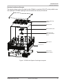
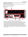
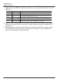
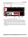
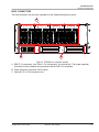
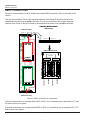
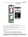
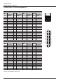
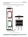
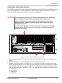
OP5600 HILBOX USER GUIDE Real-Time Simulator www.opal-rt.com Published by OPAL-RT Technologies, Inc. 1751 Richardson, suite 2525 Montreal, Quebec, Canada H3K 1G6 www.OPAL-RT.com © 2011 OPAL-RT Technologies, Inc. All rights reserved Printed in Canada SYMBOL DEFINITIONS The following table lists the symbols used in this document to denote certain conditions: Symbol Definition ATTENTION: Identifies information that requires special consideration TIP: Identifies advice or hints for the user, often in terms of performing a task REFERENCE _ INTERNAL: Identifies an additional source of information within the bookset. CAUTION Indicates a situation which, if not avoided, may result in equipment or work (data) on the system being damaged or lost, or may result in the inability to properly operate the process. Indicates a situation where users must observe precautions for handling electrostatic sensitive devices. ! ! iii CAUTION: Indicates a potentially hazardous situation which, if not avoided, may result in minor or moderate injury. It may also be used to alert against unsafe practices. WARNING: Indicates a potentially hazardous situation which, if not avoided, could result in serious injury or death. Opal-RT Technologies OP8620 Connection Box User Guide CONTENTS OP5600 SIMULATOR............................................................................................................................... 7 INTRODUCTION................................................................................................................................... 7 SIMULATOR ARCHITECTURE............................................................................................................. 8 configuration options. .........................................................................................................................................8 Simulator Architecture Example....................................................................................................................................... 9 RECEIVING AND VERIFICATION....................................................................................................... 10 standard hardware. ...........................................................................................................................................10 Installation and Configuration...........................................................................................................................10 HARDWARE CONFIGURATION.......................................................................................................... 11 spartan 3 (op5142) configuration. ...................................................................................................................11 Front Connectors........................................................................................................................................................... 11 virtex 6 (ml605) configuration.........................................................................................................................13 back connectors................................................................................................................................................15 DB37F CONNECTIONS...................................................................................................................... 16 OP5600 DB37 PIN ASSIGNMENTS .................................................................................................. 18 RJ45 CONNECTIONS......................................................................................................................... 19 RJ45 CHANNEL ASSIGNMENTS ...................................................................................................... 20 connecting monitoring devices...........................................................................................................................21 OP5330 DIGITAL TO ANALOG CONVERTER ...................................................................................... 23 DESCRIPTION.................................................................................................................................... 23 requirements.....................................................................................................................................................23 Software......................................................................................................................................................................... 23 Hardware........................................................................................................................................................................ 23 features. ...........................................................................................................................................................23 offset and gain calibration. ...............................................................................................................................23 SCHEMATICS...................................................................................................................................... 24 TYPICAL APPLICATIONS................................................................................................................... 24 OP5340 ANALOG TO DIGITAL CONVERTER (0.5 MSPS)................................................................... 25 DESCRIPTION ................................................................................................................................... 25 requirements.....................................................................................................................................................25 Software......................................................................................................................................................................... 25 Hardware........................................................................................................................................................................ 25 features. ...........................................................................................................................................................25 offset and gain calibration. ...............................................................................................................................25 SCHEMATICS...................................................................................................................................... 26 input gain selection. ..........................................................................................................................................26 input gain calculations.......................................................................................................................................28 5 Opal-RT Technologies OP5600 System User Guide OP5341 ANALOG TO DIGITAL CONVERTER (2 MSPS)...................................................................... 31 DESCRIPTION ................................................................................................................................... 31 requirements.....................................................................................................................................................31 Software......................................................................................................................................................................... 31 Hardware........................................................................................................................................................................ 31 FEATURES.......................................................................................................................................... 31 offset calibration..............................................................................................................................................31 SCHEMATICS...................................................................................................................................... 32 input gain calculations.......................................................................................................................................33 OP5353 32 DIN SIGNAL CONDITIONING MODULE............................................................................ 35 DESCRIPTION ................................................................................................................................... 35 requirements.....................................................................................................................................................35 Software......................................................................................................................................................................... 35 Hardware........................................................................................................................................................................ 35 features. ...........................................................................................................................................................35 INTERFACES................................................................................................................................................................. 36 Inputs............................................................................................................................................................................. 36 power configuration .........................................................................................................................................37 TYPICAL APPLICATIONS................................................................................................................... 38 OP5354 32 DOUT SIGNAL CONDITIONING MODULE........................................................................ 41 DESCRIPTION ................................................................................................................................... 41 requirements.....................................................................................................................................................41 Software......................................................................................................................................................................... 41 Hardware........................................................................................................................................................................ 41 features. ...........................................................................................................................................................41 outputs. ............................................................................................................................................................42 TYPICAL APPLICATION...................................................................................................................... 43 SPECIFICATIONS ................................................................................................................................. 45 OP5600 SIMULATOR SPECIFICATIONS............................................................................................ 45 OP5620 8 I/O FLAT CARRIER SPECIFICATIONS.............................................................................. 46 OP5330 DIGITAL TO ANALOG CONVERTER SPECIFICATIONS...................................................... 47 OP5340 ANALOG TO DIGITAL CONVERTER (0.5 MSPS) SPECIFICATIONS.................................. 48 OP5341 ANALOG TO DIGITAL CONVERTER (2 MSPS) SPECIFICATIONS..................................... 49 OP5353 32 DIN SPECIFICATIONS..................................................................................................... 50 OP5354 DOUT SPECIFICATIONS...................................................................................................... 51 LIMITED WARRANTY............................................................................................................................. 53 limited warranty................................................................................................................................................53 return policy.....................................................................................................................................................53 exclusions.........................................................................................................................................................53 warranty limitation and exclusion.......................................................................................................................54 .....................................................................................................................54 ..........................................................................................................................................54 disclaimer of unstated warranties limitation of liability OP5600 System User Guide Opal-RT Technologies 6 OP5600 Simulator Introduction OP5600 SIMULATOR INTRODUCTION The OP5600 is a complete simulation system capable of operating with either Spartan 3 or Virtex 6 FPGA platforms. It is designed to be used either as a desktop (or shelf top) or as a more traditional rack mount. It contains a powerful Target Computer and a flexible, high-speed Front End Processor and a signal conditioning stage. The new design makes it easier to use with standard connectors (DB37, RJ45 and mini-BNC) without the need for input/output adaptors and allows quick connections for monitoring. The front of the chassis provides the monitoring interfaces and monitoring connectors, while the back of the chassis provides access to the FPGA monitoring connections, all I/O connectors, power cable and main power switch. Inside, the main housing is divided into two sections, each with a specific purpose and connected only by a DC power cable and a PCIe cable: In its standard configuration, the lower part of the chassis contains a powerful target computer that can be added to a network of simulators or can act as a standalone. The target computer includes the following features: • • • • • ATX motherboard with up to 12 cores 6 DRAM connectors 250 Mb hard disk 600 W power supply PCIe boards (up to 8 slots, depending on the configuration). The upper section contains the conditioning modules and a high speed Front-End Processor (this includes the DC supplies used for analog and digital signals). The upper section includes the following devices: • Flat carrier capable of connecting up to 8 mezzanine boards, depending on the configuration • Type B mezzanine boards are available in several types, including (but not limited to): -- OP5353, 32 digital inputs -- OP5354, 32 digital outputs -- OP5330, 16 analog inputs -- OP5340, 16 analog outputs • Front-End processor (Spartan or Virtex) able to process conditioning signals and execute fast models previously downloaded through the PCIe link. This PCIe link is used to transmit and receive data between the target and the front-end processor. OP5600 HILbox User Guide OPAL-RT Technologies 7 OP5600 Simulator Simulator Architecture SIMULATOR ARCHITECTURE configuration options The OP5600 is available in a number of different configurations that make it easier to integrate into your environment: Platform Option 1 Option 2* Option 3** Spartan 3 (OP5142) With target computer configuration (2.4 or 3.3 GHz), up to 12 cores (Standard) See Figure 1 Without target computer. With external PCIe Extender cable x1 Without target computer. With PCIe fiber optic remote Virtex 6 (ML605) With target computer configuration (2.4 or 3.3 GHz), up to 12 cores Without target computer. With external PCIe Extender cable x8 Without target computer. With PCIe fiber optic remote The following images illustrate the simulator’s architecture for each option using assembly views of the simulation hardware components within the OP5600 chassis. * Option 2 is designed for use with a maximum cable length of 2m. ** Option 3 is designed for use with a maximum fiber optic cable length of 2 Km. 8 OPAL-RT Technologies OP5600 HILbox User Guide OP5600 Simulator Simulator Architecture Simulator Architecture Example The example shown is only to illustrate how the OP5600 is assembled. OPAL-RT strictly prohibits users from opening the OP5600. Opening the unit will render the warranty null and void. Signal conditioning modules Carrier board OP5142 FPGA board FPGA monitoring/ PCIe synchronisation board Upper section optional rackmount rail Lower section Target Computer Figure 1: OP5600 with Spartan 3 and target computer OP5600 HILbox User Guide OPAL-RT Technologies 9 OP5600 Simulator Receiving and Verification RECEIVING AND VERIFICATION After opening the package, remove the equipment and components. Make sure that all the items described in “standard hardware” are actually in the box and are undamaged. standard hardware The OP5600 Real-Time Simulator includes the following basic hardware: Item Description Part Number OP5600 simulator Complete simulator with either QNX or Redhat O/S N/A System Integration binder RT-LAB software CD O/S CD (Redhat or QNX) Documentation CD N/A Mini-BNC cables (4) 2 m (6 ft 6”) adapter cables for mini-BNC to BNC. 75 Ohms simplex MBBN1PP-3 RJ45 cables (4) 61cm (24”) RJ45 cables C-02B-CAT6 DB37M breakout board Provides extended space for connections BRKSD37M-R Dual row breakout board Provides extended space for connections BRK2X20 Flat cable IDC 40 pin IDC cable CPWLS4104 Power cable 1.83 m (6’) power cord, black (10A 125V) CPC06 OPAL-RT strongly recommends the use of anti-static wrist straps whenever handling any electronic device provided by OPAL-RT. Damage resulting from electrostatic charges will not be covered by the manufacturer’s warranty. Installation and Configuration The new design means that installation is simply a matter of placing the chassis on a shelf or a desktop, or inserting it into a traditional rack and connecting the cables. If the system is configured with the Virtex 6, ML605 FPGA board, there is a maximum of 6 signal conditioning mezzanines (these will be in groups 1, 2 and 4 on the carrier board). If the system is configured with the Spartan 3, OP5142 signal conditioning board, there is maximum of eight mezzanines allowed. 10 OPAL-RT Technologies OP5600 HILbox User Guide OP5600 Simulator Hardware Configuration HARDWARE CONFIGURATION The interfaces provided on the OP5600 simulator may vary depending on the system configuration selected, Virtex 6 (ML605) or Spartan 3 (OP5142). spartan 3 (op5142) configuration Front Connectors B A OP5600 HILbox POWER SYNC PC COMM FAULT RUN USER Group 1 OPAL-RT TECHNOLOGIES Group 2 Group 3 Group 4 Power Reset Power HDD NIC1 A A A A B B B B C C C C D D D D NIC2 Pwr Fail Overheat /Fan Fail F E D C Figure 2: OP5600 front connector panels (Spartan 3) A. Inactive section. These functions are currently in development and unavailable. B. 4 panels of RJ45 connectors provide connections to monitor output from mezzanine I/O boards. Each connector is linked to front and back mezzanines on the carrier board. Analog mezzanines (channels 0-15) will use only the first column of connectors. Digital mezzanines will use both columns (channels 0-15 in the first column and channels 16-31 on the second column of connectors). See “DB37F Connections” and “RJ45 connections” for more detailed information. C. Monitoring RJ45 connectors with mini-BNC terminals: RJ45 cables connect from a channel on an RJ45 panel (B) to one of four RJ45 monitoring connectors (C). Mini-BNC connectors allow for quick cable connections to monitoring devices (such as an oscilloscope). See “connecting monitoring devices” for details. OP5600 HILbox User Guide OPAL-RT Technologies 11 OP5600 Simulator Hardware Configuration D. Target computer monitoring interface. Two push buttons include POWER in top position to start the target computer and RESET in the bottom position to reset the target computer. There are 6 LED indicators: LED NAME Description Green Power On indicates that the unit is powered up. Green HDD On indicates that the hard disk drive is operating. Green NIC1 On indicates that network port 1 is in use. Green NIC2 On indicates that network port 2 is in use. Red Power Fail On indicates a power fault. Red Overheat/Fan Fail On indicates either that unit has overheated or a fan fault. E. Optional PCI or PCIe connector slots (by default, these spaces will be covered by blank plates if there are no optional PCI cards. If there are PCI cards installed, the spaces will contain the PCI connectors). F. Standard computer connectors (left to right): mouse and keyboard, USB ports, monitor, network ports. Although use of these connectors is optional but not required to use the OP5600, one network port is required for network connection. 12 OPAL-RT Technologies OP5600 HILbox User Guide OP5600 Simulator Hardware Configuration virtex 6 (ml605) configuration The Virtex 6 monitoring interface is nearly identical to the Spartan 3, with RJ45 monitoring panels. B A OP5600 HILbox POWER SYNC PC COMM FAULT RUN USER Group 1 OPAL-RT TECHNOLOGIES Group 2 Group 3 Group 4 Power Reset Power HDD NIC1 A A A A B B B B C C C C D D D D NIC2 Pwr Fail Overheat /Fan Fail F E D C Figure 3: OP5600 front connector panels (Virtex 6) A. Inactive section. These functions are currently unavailable. B. 3 panels of RJ45 connectors provide connections to monitor output from mezzanine I/O boards. Each connector is linked to front and back mezzanines on the carrier board. Analog mezzanines (channels 0-16) will use only the first column of connectors. Digital mezzanines will use both columns (channels 0-15 in the first column and channels 16-31 on the second column of connectors). See the mezzanines connector image and the RJ45 pinouts for more detailed information. C. Monitoring RJ45 connectors with mini-BNC terminals: RJ45 cables connect from a channel on an RJ45 panel (B) to one of four RJ45 monitoring connectors (C). Mini-BNC connectors allow for quick cable connections to monitoring devices (such as an oscilloscope). See “connecting monitoring devices” for details. OP5600 HILbox User Guide OPAL-RT Technologies 13 OP5600 Simulator Hardware Configuration D. Target computer monitoring interface. Two push buttons include POWER in top position to start the Target computer and RESET in the bottom position to reset the Target computer. There are 6 LED indicators: LED NAME Description Green Power On indicates that the unit is powered up. Green HDD On indicates that the hard disk drive is operating. Green NIC1 On indicates that network port 1 is in use. Green NIC2 On indicates that network port 2 is in use. Red Power Fail On indicates a power fault. Red Overheat/Fan Fail On indicates either that unit has overheated or a fan fault. E. Optional PCI or PCIe connector slots (by default, these spaces will be covered by blank plates if there are no optional PCI cards. If there are PCI cards installed, the spaces will contain the PCI connectors). F. Standard computer connectors (left to right): mouse and keyboard, USB ports, monitor, network ports. Although use of these connectors is optional but not required to use the OP5600, one network port is required for network connection. 14 OPAL-RT Technologies OP5600 HILbox User Guide OP5600 Simulator Hardware Configuration back connectors The back connectors are the same, regardless of the selected configuration option. A Group 4 Group 3 B Group 2 Group 1 C Figure 4: OP5600 rear connector panels A. DB37F I/O connectors (see “Table 1: Pin Assignments” for more details). The image (opposite) illustrates the links between the mezzanines and the DB37 I/O connectors B. Power connector and power On/Off switch C. Optional PCI or PCIe connector slots. OP5600 HILbox User Guide OPAL-RT Technologies 15 OP5600 Simulator DB37F Connections DB37F CONNECTIONS Each pair of mezzanines (A & B) is linked to four female DB37 connectors (I/Os) on the back of the chassis: The first two connectors (left to right) represent channels from Group B, which are linked to the conditioned channels from the back mezzanine. The last two connectors (left to right) represent channels from Group A, which are linked to the conditioned channels from the front mezzanine. ANALOG MEZZANINES (top view) OP5600 Rear (DB37) GROUP 1A GROUP 1B GROUP 1B GROUP 1A Connector rear view DB37 connector panel NOT USED channels 0-15 NOT USED GROUP1A GROUP 1A channels 0-15 GROUP1B Group 4 GROUP 1B OP5600 Front (RJ45) Figure 5: DB37 connection to mezzanines If the front mezzanine is an analog module (DAC or ADC), the 16 channels are on connector A, P1 and P2 does not carry any signals. If the back mezzanine is an analog module (DAC or ADC), the 16 channels are on connector B, P1. P2 does not carry any signals. 16 OPAL-RT Technologies OP5600 HILbox User Guide OP5600 Simulator DB37F Connections DIGITAL MEZZANINES (top view) OP5600 Rear (DB37) GROUP 1A GROUP 1B GROUP 1B GROUP 1A Connector rear view DB37 connector panel channels 16-31 channels 0-15 channels 16-31 GROUP1A GROUP 1A channels 0-15 GROUP1B Group 4 GROUP 1B OP5600 Front (RJ45) . Figure 6: DB37 connection to mezzanines If the front mezzanine is a digital module (Din or Dout), the first 16 channels (00 to 15) are on the connector A, P1and the next 16 channels (16 to 31) are on the A, P2. If the back mezzanine is a digital module (Din or Dout), the first 16 channels (00 to 15) are on the connector B, P1 and the next 16 channels (16 to 31) are on the B, P2. All signals are represented by a positive-negative pair that are always available on the connector pins, for example: for channel 08 : (08+, -08) INTERFACE: • • • • For a single-ended output, the negative conductor is connected to Ground. For a differential output, the positive and negative signals are on the connector. For a differential input, the connection must be between the positive/negative pair. If the input is singled-ended, user’s ground must be connected to the negative side of the pair. OP5600 HILbox User Guide OPAL-RT Technologies 17 OP5600 Simulator OP5600 DB37 Pin Assignments OP5600 DB37 PIN ASSIGNMENTS DB37 Connector A Ch. 0-15 Module pin Module pin DB37 DB37 assignment assignment Connector A Ch. 16-31 Module pin Module pin DB37 assignment assignment 1 +CH00 20 -CH00 1 +CH16 20 -CH16 2 3 4 5 6 7 7 9 10 11 12 13 14 15 16 17 18 19 +CH01 +CH02 +CH03 +CH04 +CH05 +CH06 +CH07 +CH08 +CH09 +CH10 +CH11 +CH12 +CH13 +CH14 +CH15 21 22 23 24 25 26 27 28 29 30 31 32 33 34 35 36 37 -CH01 -CH02 -CH03 -CH04 -CH05 -CH06 -CH07 -CH08 -CH09 -CH10 -CH11 -CH12 -CH13 -CH14 -CH15 2 3 4 5 6 7 7 9 10 11 12 13 14 15 16 17 18 19 +CH17 +CH08 +CH19 +CH20 +CH21 +CH22 +CH23 +CH24 +CH25 +CH26 +CH27 +CH28 +CH29 +CH30 +CH31 21 22 23 24 25 26 27 28 29 30 31 32 33 34 35 36 37 -CH17 -CH18 -CH19 -CH20 -CH21 -CH22 -CH23 -CH24 -CH25 -CH26 -CH27 -CH28 -CH29 -CH30 -CH31 DB37 1 2 3 4 5 6 7 7 9 10 11 12 13 14 15 16 17 18 19 Vuser 1 A* Connector Module pin assignment +CH00 +CH01 +CH02 +CH03 +CH04 +CH05 +CH06 +CH07 +CH08 +CH09 +CH10 +CH11 +CH12 +CH13 +CH14 +CH15 Vuser 1 B* Vrtn 1 A* B Ch. 0-15 Module pin DB37 DB37 assignment 20 -CH00 1 21 -CH01 2 22 -CH02 3 23 -CH03 4 24 -CH04 5 25 -CH05 6 26 -CH06 7 27 -CH07 7 28 -CH08 9 29 -CH09 10 30 -CH10 11 31 -CH11 12 32 -CH12 13 33 -CH13 14 34 -CH14 15 35 -CH15 16 36 17 37 Vrtn 1 B* 18 19 Vuser 2 A* Vrtn 2 A* Connector B Ch. 16-31 Module pin Module pin DB37 assignment assignment +CH16 20 -CH16 +CH17 21 -CH17 +CH08 22 -CH18 +CH19 23 -CH19 +CH20 24 -CH20 +CH21 25 -CH21 +CH22 26 -CH22 +CH23 27 -CH23 +CH24 28 -CH24 +CH25 29 -CH25 +CH26 30 -CH26 +CH27 31 -CH27 +CH28 32 -CH28 +CH29 33 -CH29 +CH30 34 -CH30 +CH31 35 -CH31 36 Vuser 2 B* 37 Vrtn 2 B* DB37 connector panel silkscreen 1 20 -00 -01 -02 -03 -04 -05 -06 -07 -08 -09 -10 -11 -12 -13 -14 -15 00+ 01+ 02+ 03+ 04+ 05+ 06+ 07+ 08+ 09+ 10+ 11+ 12+ 13+ 14+ 15+ Vrtn Vuser 19 37 Table 1: Pin Assignments *Vuser is available on Dout only. 18 OPAL-RT Technologies OP5600 HILbox User Guide OP5600 Simulator RJ45 connections RJ45 CONNECTIONS Each RJ45 monitoring panel on the front of the OP5600 simulator connects to front and back mezzanines. The following images illustrate how the mezzanines are linked to the connectors. Top View OP5600 Rear (DB37) GROUP1A GROUP1B GROUP1A GROUP1B GROUP1B channels 0-15 GROUP1B ANALOG: NOT USED Digital Channels 16-31 GROUP1B ANALOG: NOT USED Digital Channels 16-31 GROUP1A GROUP1A channels 0-15 GROUP1A OP5600 Front (RJ45) Figure 7: RJ45 connection to mezzanines OP5600 HILbox User Guide OPAL-RT Technologies 19 OP5600 Simulator RJ45 channel Assignments RJ45 CHANNEL ASSIGNMENTS Each mezzanine is assigned two columns of RJ45 connectors. Each column represents a series of channels, divided into 4 channels per jack, as shown in Figure 8. SLOT xA Column 1: Channels 0-3 Channels 4-7 Channels 8-11 Channels 12-15 Column 2: Channels 16-19 Channels 20-23 Channels 24-27 Channels 28-31 0-3 16-19 4-7 20-23 8-11 24-27 12-15 28-31 SLOT xB Analog boards use only channels 0-15 Digital boards use channels 0-31 Figure 8: RJ45 channel assignments 20 OPAL-RT Technologies OP5600 HILbox User Guide OP5600 Simulator RJ45 channel Assignments connecting monitoring devices The OP5600 simulator offers quick, single-ended connections, through RJ45 and mini BNC connectors, to any monitoring device (i.e. oscilloscope, etc.). These mini-BNC jacks let you monitor 4 channels individually. Simply follow these instructions (as illustrated in Figure 9): CAUTION The monitoring board has a gain of 0.1 to allow higher signals to be read. Oscilloscopes must be adjusted with a gain of 10 to compensate and ensure a better reading. Only connect RJ45 cables from upper section (A) monitoring jacks to lower section monitoring panel (B, as shown). Connecting any other cable or device may result in damage to the equipment. The network cable must only be connected to the standard computer connector network jack (see page 12). DO NOT connect the network cable in any jack other than the jack intended for that purpose. A OP5600 HIL Box POWER SYNC PC COMM FAULT RUN USER Group 1 OPAL-RT TECHNOLOGIES Group 2 Group 3 Group 4 Power Reset Power HDD NIC1 A A A A B B B B C C C C D D D D NIC2 Pwr Fail Overheat /Fan Fail B C Figure 9: How to connect cables for monitoring 1. Connect one end of the RJ45 cable to the desired channels (A). See Figure 8 for RJ45 connector pinouts 2. Connect the other end of the RJ45 cable to the monitoring connector (B) 3. Connect a mini-BNC cable to each BNC jack (C) and connect the other end of the cable to the desired monitoring device. The mini-BNC jacks each connect to one of the 4 channels of the RJ45 Connector (A). In the example shown in Figure 8, the RJ45 cable is connected to channels 28-31. The mini-BNC cable jacks, identified as A, B, C, D, represent each channel in the following order; A = channel 28, B = channel 29, C = channel 30 D = channel 31. OP5600 HILbox User Guide OPAL-RT Technologies 21 OP5600 Simulator RJ45 channel Assignments 22 OPAL-RT Technologies OP5600 HILbox User Guide OP5330 Digital to Analog Converter Description OP5330 DIGITAL TO ANALOG CONVERTER DESCRIPTION The OP5330 digital to analog converter (DAC) provides 16 single-ended digital output channels. Each channel uses a 16-bit resolution digital-to-analog converter. It is a part of the OP5000 series of optional modules for OPAL-RT’s state of the art HIL (hardware-in-the-loop) systems, intended for use with OPAL-RT carrier boards (OP5130, OP5220, OP5222, OP5600, OP6228). Each OP5330 can sample up to 1 MS/s, giving a total throughput of 8 MS/s, all channels are simultaneously sampled. The onboard EEPROM provides offset and gain data adjustment written during the calibration process, as well as over-voltage protection. By default, the maximum output signal is set to ±16 volts. requirements Software • RT-LAB 8.4.0 and higher Hardware • OPAL-RT simulator: -- OP5600 series simulator -- OP5000 series of hardware-in-the-loop simulators -- OPAL-RT I/O expansion box (only for use with OPAL-RT simulators) • OPAL-RT carrier board: -- OP5130, OP5220, OP5222, OP5600, OP6228 features • • • • • 16 single-ended analog output channels All outputs are sampled simultaneously at up to 1 MS/s 16 bit resolution ±15 V voltage range output ±15 mA maximum current per channel offset and gain calibration The OP5330 contains a serial EEPROM to store the module identification, calibration information and other important information. Each OP5330 is factory calibrated after assembly; during calibration, gain and offset are adjusted to ensure accurate target output values at ±20 mV noise and offset. OP5600 HILbox User Guide OPAL-RT Technologies 23 OP5330 Digital to Analog Converter Typical Applications SCHEMATICS Figure 10 represents a simplified schematic of one OP5330 module channel. It is composed of three stages: the first stage consists of one gain DAC and one offset DAC; the second stage consists of a signal DAC with an operational amplifier that allows for gain adjustments; the third stage consists of an operational amplifier that receives final signal value and integrates the offset. STAGE 2 STAGE 1 SIGNAL DATA GAIN DATA STAGE 3 VREF SIGNAL DAC RJ45 OUTPUT + - GAIN DAC + RJ45 GND - OFFSET DATA DB37 OUTPUT + + OFFSET DAC DB37 GND Figure 10: Output DAC circuit TYPICAL APPLICATIONS The following diagram provides an example of a typical application using the OP5330. Figure 11: OP5330 typical application 24 OPAL-RT Technologies OP5600 HILbox User Guide OP5340 Analog to Digital converter (0.5 MSPS) Description OP5340 ANALOG TO DIGITAL CONVERTER (0.5 MSPS) DESCRIPTION The OP5340 Analog to Digital converter (ADC) is a part of the OP5000 series of optional modules for OPAL-RT’s state of the art HIL (hardware-in-the-loop) systems, intended for use with OPAL-RT carrier boards (OP5130, OP5220, OP5222, OP5600, OP6228). Designed for OPAL-RT’s simulation systems, the OP5340 converts analog signals to digital. Each ADC can sample up to 500 kS/s, giving a total throughput of 8 MS/s, all channels are simultaneously sampled. The on-board EEPROM provides offset and gain data adjustment written during the calibration process, as well as over-voltage protection. The OP5340 module provides 16 differential analog input channels. Each channel uses a 16bit resolution analog-to-digital converter. The OP5340 module also has input signal conditioning capabilities that allow the user to apply a signal range from ±20v up to ±120v on the inputs. By default, the maximum input signal is set to ±20 volts. requirements Software • RT-LAB 8.4.0 and higher Hardware • OPAL-RT simulator: -- OP5000 series hardware-in-the-loop simulator -- OPAL-RT I/O expansion box (only for use with OPAL-RT simulators) • OPAL-RT carrier board: -- OP5130, OP5220, OP5222, OP5600, OP6228 features • • • • • • 16 differential analog input channels All inputs are sampled simultaneously at up to 500 kSPS 16 bit resolution 500 KΩ input impedance ±20 V input voltage range ±240 input range up to 120V offset and gain calibration The OP5340 contains a serial EEPROM to store the module identification, calibration information and any other important information. Each OP5340 module is calibrated after assembly; during calibration, gain and offset are adjusted to ensure accurate target output values at ±20 mV noise and offset. OP5600 HILbox User Guide OPAL-RT Technologies 25 OP5340 Analog to Digital converter (0.5 MSPS) Schematics SCHEMATICS Figure 12 represents a simplified schematic of one OP5340 module channel. It is composed of three stages: the first stage consists of one operational amplifier that works in differential input mode and permits gain adjustment; the second stage, the level shifter, forms the signal for the A/D converter input; the third stage occurs after the conversion to the digital type, as the signal is sent to the carrier board. Differential Amplifier V in Level Shifter + A / D Converter VREF VIN + VREF OUT Serial Data Out REF Figure 12: Differential input ADC circuit input gain selection Ch 00 Optional - for advanced users. The OP5340 module has user selectable input attenuation ability. By default, the maximum input voltage range is set to ±20 volts but each channel can be changed separately up to ±120 volts. The OP5340 module contains resistor networks that allow insertion of additional precision resistors to change the input attenuation. The image on the right shows the placement for the additional resistors. Please refer to the table at the end of this section for the exact relationship between channels and resistors. 26 OPAL-RT Technologies OP5600 HILbox User Guide OP5340 Analog to Digital converter (0.5 MSPS) Schematics sThe next diagram illustrates the input stage of one channel. The default values for resistors R1 and R2 were chosen to keep the maximum input voltage range of ±20 volts (40 volts) with no additional resistors. R1 Vin full range = ±20 volts Vout full range = ±1 volt (2 volts) Installed resistors: R1 = 499 kΩ R2 = 25 kΩ R2 VOUT VIN Vout Formula R1 R2 Vout Vin R1 R2 The factory installed surface mount resistors on the OP5340 module give an attenuation of 20. Vin 1 / 20 Vout OP5600 HILbox User Guide OPAL-RT Technologies 27 OP5340 Analog to Digital converter (0.5 MSPS) Schematics input gain calculations The figures below show the complete circuit with resistor Rx as the axial insertable resistor by the user. Input Gain Schematic with Rx Rx R1 - V IN + R1 R2 V OUT R2 Rx Figure 13: Input gain with Rx Vout Formula with Rx R 2 Rx Vout Vin R1 R 2 Rx Vout Formula, with Default R Values and Rx R1= 499K, R2= 25K 1 Rx Vout Vin 2 0 25 Rx Figure 14: Vout formulas Users may define the input gain value and calculate the corresponding Rx resistor value. Table 2 provides maximum range values and associated Rx resistor values (chosen in 0.1% series range). To yield the same unit of measurement, the model must compensate for any new gain value different from the original gain of 1/20. The last column provides the gain to insert in the input signal of the simulation model. Input gain Max voltage input Rx value 0.1% series range Gain to insert in the model 1/20 ±20V (or 40V) none 1 1/40 ±40V (or 80V) 24.9 kΩ 2 1/60 ±60V (or 120V) 12.4 kΩ 3 1/80 ±80V (or 160V) 8.25 kΩ 4 1/100 ±100V (or 200V) 6.20 kΩ 5 1/120 ±120V (or 240V) 4.99 kΩ 6 Table 2: Maximum Range and Resistor Values Example: an added Rx resistor of 4.99 kΩ in parallel with R2 resistor gives an attenuation of approximately 120 so the input voltage can be increased to ±120 volts (or 240 volts). 28 OPAL-RT Technologies OP5600 HILbox User Guide OP5340 Analog to Digital converter (0.5 MSPS) Schematics Table 3 shows the relationship between channel and resistor references used for the input gain changes. Resistor Network Ch 00 Channel # Resistor Rx Channel # Resistor Rx Channel 00 R164, R165 Channel 08 R172, R173 Channel 01 R180, R181 Channel 09 R188, R189 Channel 02 R166, R167 Channel 10 R174, R175 Channel 03 R182, R183 Channel 11 R190, R191 Channel 04 R168, R169 Channel 12 R176, R177 Channel 05 R184, R185 Channel 13 R192, R194 Channel 06 R170, R171 Channel 14 R178, R179 Channel 07 R186, R187 Channel 15 R193, R195 Table 3: Resistor Network Channel Identification OP5600 HILbox User Guide OPAL-RT Technologies 29 OP5341 Analog to Digital converter (2 MSPS) Features OP5341 ANALOG TO DIGITAL CONVERTER (2 MSPS) DESCRIPTION The OP5341 is a part of the OP5000 series of optional modules for OPAL-RT’s state of the art HIL (hardware-in-the-loop) systems, intended for use with with OPAL-RT carrier boards (OP5130, OP5220, OP5222, OP5600, OP6228). Designed for OPAL-RT’s simulation systems, the OP5341 converts analog signals to digital. Each ADC can sample up to 2 MSPS, giving a total throughput of 32 MS/s, all channels are simultaneously sampled. The on-board EEPROM provides offset and gain data adjustment written during the factory calibration process. The OP5341 provides 16 differential analog input channels. Each channel uses a 14-bit resolution analog-to-digital converter. The OP5341 module also has input signal conditioning capabilities that allow the user to apply a signal range from ±20v up to ±120v on the inputs. By default, the maximum input signal is factory configured to ±20 volts. requirements Software • RT-LAB 8.4.0 and higher Hardware • OPAL-RT simulator: -- OP5000 series hardware-in-the-loop simulator -- OPAL-RT I/O expansion box (only for use with OPAL-RT simulators) • OPAL-RT carrier board: -- OP5130, OP5220, OP5222, OP5600, OP6228 FEATURES • • • • • 16 differential analog input channels, 14 bits, 2 MSPS All inputs are sampled simultaneously at up to 2 MSPS 500 KΩ input impedance ±20 V input voltage range ±240 input range up to 120V offset calibration The OP5341 contains a serial EEPROM to store the module identification, calibration information and any other important information. Each OP5341 module is calibrated after assembly; during calibration, gain and offset are adjusted to ensure accurate target Input values at ±20 mV noise (including gain and offset errors). OP5600 HILbox User Guide OPAL-RT Technologies 31 OP5341 Analog to Digital converter (2 MSPS) Schematics SCHEMATICS Figure 15 represents a simplified schematic of one channel of the OP5341 modules. It is composed of three stages: the first stage consists of one operational amplifier that works in differential input mode and permits gain adjustment; the second stage, the level shifter, forms the signal for the A/D converter input; the third stage occurs after the conversion to the digital type, as the signal is sent to the carrier board. Differential Amplifier ± 20 V V in Differential Converter A / D Converter ±2V - - + + VIN+ 0 to 4 V DOUT CLK Serial Data Out Clock In REF Figure 15: Differential input ADC circuit The next diagram illustrates the input stage of one channel. The default values for resistors R1 and R2 were chosen to keep the maximum input voltage range of ±20 volts (40 volts) with no additional resistors. R1 R2 VOUT VIN R1 R2 Vin full range = ±20 volts VIN full range = ±2 volt (4 volts) Installed resistors: R1 = 499 kΩ R2 = 49.9 kΩ Vout Formula R2 Vout Vin R1 The factory installed surface mount resistors on the OP5341 module give an attenuation of 10. Vin 32 1 / 10 Vout OPAL-RT Technologies OP5600 HILbox User Guide OP5341 Analog to Digital converter (2 MSPS) Features input gain calculations The figures below show the complete circuit with resistor Rx as a surface mount resistor. Input Gain Schematic with Rx Rx R1 - V IN R1 + R2 V OUT R2 Rx Figure 16: Input gain with Rx Vout Formula with Rx R 2 Rx Vout Vin R1 R 2 Rx Vout Formula, with Default R Values and Rx R1= 499K, R2= 49.9K 1 Rx Vout Vin 1 0 49.9 Rx Figure 17: VIN formulas Users may define the input gain value and calculate the corresponding Rx resistor value. Table 4 provides maximum range values. To yield the same unit of measurement, the model must compensate for any new gain value different from the original gain of 1/20. The last column provides the gain to insert in the input signal of the simulation model. Input Gain Max Voltage Input Gain to insert in the model 1/10 ±20V (or 40V) .5 1/20 ±40V (or 80V) 1 1/30 ±60V (or 120V) 1.5 1/60 ±80V (or 160V) 2 1/50 ±100V (or 200V) 2.5 1/60 ±120V (or 240V) 3 Table 4: Maximum range values OP5600 HILbox User Guide OPAL-RT Technologies 33 OP5341 Analog to Digital converter (2 MSPS) Schematics 34 OPAL-RT Technologies OP5600 HILbox User Guide OP5353 32 Din Signal Conditioning Module OP5353 32 DIN SIGNAL CONDITIONING MODULE DESCRIPTION The OP5353 is a part of the OP5000 series of optional, versatile signal conditioning modules for OPAL-RT’s state of the art HIL (hardware-in-the-loop) systems. Designed for OPAL-RT’s simulation systems, the OP5353 provides digital input signals with specific voltage conditioning. The optical isolation of the OP5353 inputs make it ideal for environments where voltage isolation is required. The OP5353 features 32 optically isolated input channels. All are sampled simultaneously for additional simulation accuracy. It is perfectly suited to interface real life environment signals to TTL or differential levels for RT-LAB simulator, providing perfect electrical isolation and discharge protection. requirements Software • RT-LAB 8.4.0 and higher Hardware • OP5600 HILbox simulator • OP5620 carrier board. features • • • • • • • • 32 optically isolated input channels. All inputs are sampled simultaneously, at up to 10 MSPS. Inputs are read in parallel for any size bus simulation. Hardware configurable filters, and conditioning inputs for customization. Choice of sink or source inputs connection (anode and cathode side available). Minimum current input of 3.6 mA. 4V to 100V input voltage range. 30V maximum reverse protection OP5600 HILbox User Guide OPAL-RT Technologies 35 OP5353 32 Din Signal Conditioning Module INTERFACES Inputs The optically isolated inputs accept a wide input voltage range, from 4 to 100 Volts, according to user requirements. They have a low threshold current; typically 3.6 mA. Each input has a reverse voltage protection of up to 30 volts provided by a diode. Opto-Isolated Digital Input Simulator User +3V3/+2V5 Din_FPGA Current limit = 3.6 mA A Reverse protection = 30V Din + OPTIONAL FILTER Din - Figure 18: OP5353 Isolated digital input drawing The signal conditioning module inputs have both anode and cathode sides available to the user (on the I/O connector). Din + I 3.6 mA Din - Figure 19: Both Din + and Din - are available to the user When current flows from Din+ to Din -, the output of opto-coupler A is low and the Din_FPGA signal is low. When no current flows, the opto-coupler output A is high and the Din_FPGA signal is high. 36 OPAL-RT Technologies OP5600 HILbox User Guide OP5353 32 Din Signal Conditioning Module power configuration The digital input circuit needs a 5 V supply source to power the onboard circuitry. This source is connected to the computer’s 5 VDC. Client side OP5353 Din Rail + Vcc FPGA TC4049/4050 3.6 mA Figure 20: Typical digital input circuit To work properly, the OPAL-RT digital input optical isolator needs a typical current of 3.6 mA. OP5600 HILbox User Guide OPAL-RT Technologies 37 OP5353 32 Din Signal Conditioning Module Typical Applications TYPICAL APPLICATIONS The diagrams below illustrate typical application examples. Client side OP5353 Din VDC+ Activate High Dout Rail + FPGA 3.6 mA LOAD GND Figure 21: Typical high side activation (user high Dout) OP5353 Din Client side VDC+ Rail+ FPGA 3.6 mA LOAD Activate Low Dout GND Figure 22: Typical low side activation (user low Dout) 38 OPAL-RT Technologies OP5600 HILbox User Guide OP5353 32 Din Signal Conditioning Module Typical Applications Client side OP5353 Din Activate High Dout Rail+ VDC+ FPGA 3.6 mA LOAD GND Figure 23: Typical high side open circuit detection OP5353 Din Client side Rail+ LOAD FPGA 3.6 mA Activate Low Dout GND Figure 24: Typical low side open circuit detection OP5600 HILbox User Guide OPAL-RT Technologies 39 OP5353 32 Din Signal Conditioning Module Typical Applications 40 OPAL-RT Technologies OP5600 HILbox User Guide OP5354 32 DOUT Signal Conditioning Module OP5354 32 DOUT SIGNAL CONDITIONING MODULE DESCRIPTION The OP5354 is a part of the OP5000 series of optional, versatile Signal Conditioning Modules for OPAL-RT’s state of the art HIL (hardware-in-the-loop) systems. Designed for OPAL-RT’s simulation systems, the OP5354 provides digital output signals with specific voltage conditioning. The galvanic isolation of the OP5354 outputs make it ideal for environments where voltage isolation is required. The OP5354 features 16 or 32 galvanically isolated output channels and all are outputted simultaneously. It is perfectly suited to interface TTL or differential signals to real-life environment signals, providing perfect electrical isolation with full short-circuit protection. requirements Software • RT-LAB 8.4.0 and higher Hardware • OP5600 and OP7000 simulators. • OPAL-RT OP5620 and OP7220 carrier boards. features • • • • • • 32 galvanically isolated output channels All outputs are outputted simultaneously, at up to 40 MSPS. Short-circuit protected by auto-resettable fuse. Outputs stage is a Push-Pull type circuit All outputs accept voltage of 5 to 30V and the output current is up to ±50mA. Voltage supplied by user side. OP5600 HILbox User Guide OPAL-RT Technologies 41 OP5354 32 DOUT Signal Conditioning Module outputs Each galvanically isolated output has a push-pull transistor. It can sink up to 50 mA continuous, and up to +30V according to user requirements. It is current protected by resettable 150 mA fuse (PTC). The galvanic isolation circuitry is powered by an internal isolated DC supply. ! CAUTION: If Vuser is connected to the simulator, the output voltage DOUT would be the same as Vuser as long as no RT-LAB model is running (output transistor is open). Figure 25: Isolated digital output schematic NOTE: Vrtn is normally the Vuser_GND. 42 OPAL-RT Technologies OP5600 HILbox User Guide OP5354 32 DOUT Signal Conditioning Module Typical Application TYPICAL APPLICATION The diagram below illustrates typical application examples. Figure 26: OP5354 Typical source (push-pull) application OP5600 HILbox User Guide OPAL-RT Technologies 43 Specifications OP5600 Simulator Specifications SPECIFICATIONS OP5600 SIMULATOR SPECIFICATIONS Product name OP5600 HIL Box Power supply Universal input and active power factor correction 650W continuous power DC to DC converters for analog voltage I/O connectors Spartan 3: 4 panels of 4 DB37F connectors Virtex 6: 3 panels of 4 DB37F connectors Monitoring connectors Spartan 3: 4 panels of RJ45 connectors Virtex 6: 3 panels of RJ45 connectors PC interface Standard PC connectors (monitor, keyboard, mouse and network) PCI slots 2 PCI 4 PCIe Carrier board Spartan 3 configuration: 8 mezzanines Virtex 6 configuration: 6 mezzanines Hard disk 250 Gb, 7200 rpm, SATA Dimensions 48.3 x 45.7 x 17.8cm (19” x 18” x 7”) WxDxH Weight With PC: 9.07 - 11.34 Kg (20 lbs to 25 lbs) Without PC: 4.54 x 5.9 Kg (10 lbs to 13 lbs) Operating temperature 10 to 40 ºC (50 to 104ºF) Storage temperature -55 to 85ºC (-67 to 185ºF) Relative humidity 10 to 90% non-condensing Maximum altitude 2000 m (6562 ft.) OP5600 HILbox User Guide OPAL-RT Technologies 45 Specifications OP5330 Digital to Analog Converter Specifications OP5330 DIGITAL TO ANALOG CONVERTER SPECIFICATIONS Product Name OP5330 Part Number 126-0157 Number of channels 16 single-ended Resolution: 16 bits Default range ± 15 Volts Maximum current 15 mA Max. Sampling Frequency 1 MS/s Min Conversion / Acquisition Time 1 μs per channel DAC Type 8 x Dual DAC with 50 MBit/s Serial Output Transfer CMRR 100 dB Calibration Programmable gain and offset calibration for each D/A. Calibration factors are stored in on-board non-volatile memory (EEPROM) Maximum noise 20 mV peak-to-peak Recommended warm-up time 5 min. Calibration interval as required Dimensions 6.60 cm x 12.50 cm (2.6” x 4.92”) I/O connector: 80-pin high speed header to carrier Operating temperature 10 to 40 ºC (50 to 104ºF) Storage temperature -55 to 85ºC (-67 to 185ºF) Relative humidity 10 to 90%, non condensing Maximum altitude 2,000 m (6562 ft.) 46 OPAL-RT Technologies OP5600 HILbox User Guide Specifications OP5340 Analog to Digital converter (0.5 MSPS) Specifications OP5340 ANALOG TO DIGITAL CONVERTER (0.5 MSPS) SPECIFICATIONS Product name OP5340 (16 analog inputs - 500 KSPS) Part number 126-0112 Number of channels 16 differentials Resolution 16 bits Max. Sampling Frequency 500 KSPS Min Conversion / Acquisition Time 2.5 μs per channel ADC Type 8 x Dual ADC with 10 MBit/s Serial Output Transfer Nominal Input Ranges (V) Positive Full Scale Negative Full Scale +120.0 -120.0 +100.0 -100.0 +80.0 -80.0 +60.0 -60.0 +40.0 -40.0 +20.0 (Hardware default value) -20.0 No missing codes resolution 14 bits min. Integral nonlinearity (INL) ±8 LSB max. (Typical: ±3 LSB) Differential nonlinearity (DNL) ±1.5 LSB typ. (0 to +70°C) CMRR 90 dB Bandwidth Small signal (-3 dB): 820 kHz Large signal (0.1% THD): 55 kHz System noise 1.8 LSB rms (including quantization) Calibration Calibration factors are stored in on-board non-volatile memory (flash memory). This memory is not accessible for calibration.. Recommended warm-up time 5 min. Calibration interval as required Dimensions 6.60 cm x 12.50 cm (2.6” x 4.92”) I/O connector 80-pin high speed header to carrier Environmental Operating temperature 10 to 40 ºC (50 to 104ºF) Storage temperature -55 to 85ºC (-67 to 185ºF) Relative humidity 10 to 90%, non condensing Maximum altitude 2,000 m (6562 ft.) OP5600 HILbox User Guide OPAL-RT Technologies 47 Specifications OP5341 Analog to Digital converter (2 MSPS) Specifications OP5341 ANALOG TO DIGITAL CONVERTER (2 MSPS) SPECIFICATIONS Product name OP5341 (16 analog inputs - 2 MSPS) Part number 126-0301 Number of channels 16 differentials Resolution 14 bits Max. Sampling Frequency 2 MSPS Min Conversion / Acquisition Time 500 nanoseconds per channel ADC Type 8 x Dual ADC with 40 MBit/s Serial Output Transfer Nominal Input Ranges (V) Positive Full Scale Negative Full Scale +120.0 -120.0 +100.0 -100.0 +80.0 -80.0 +60.0 -60.0 +40.0 -40.0 +20.0 (Hardware default value) -20.0 Bandwidth Small signal (-3 dB): 820 kHz Large signal (0.1% THD): 55 kHz System noise 1.8 LSB rms (including quantization) Calibration Calibration factors are stored in on-board non-volatile memory (flash memory). This memory is not accessible for calibration.. Recommended warm-up time 5 min. Calibration interval as required Dimensions 6.60 cm x 12.50 cm (2.6” x 4.92”) I/O connector 80-pin high speed header to carrier Operating temperature 10 to 40 ºC (50 to 104ºF) Storage temperature -55 to 85ºC (-67 to 185ºF) Relative humidity 10 to 90%, non condensing Maximum altitude 2,000 m (6562 ft.) 48 OPAL-RT Technologies OP5600 HILbox User Guide Specifications OP5353 32 Din Specifications OP5353 32 DIN SPECIFICATIONS Product name OP5353 (32 opto-isolated digital inputs) Part number 126-0312 Number of channels 32 digital inputs Isolation Optical isolator Connection mode Anode and cathode available on connector Input current 3.6 mA, current limiting diode Reverse voltage protection Schottky diode Maximum reverse voltage protection 30 Volts Detection threshold Separate Schmitt Trigger Voltage range 4 to 100 Vdc Delay Low-to-High 110 ns Delay High-to-Low 60 ns Rise/Fall times 6 ns/6 ns Form factor Mezzanine Type B Dimensions 6.60 cm x 12.50 cm (2.6” x 4.92”) I/O connector 80-pin high speed header to carrier Operating temperature 10 to 40 ºC (50 to 104ºF) Storage temperature -55 to 85ºC (-67 to 185ºF) Relative humidity 10 to 90%, non condensing Maximum altitude 2,000 m (6562 ft.) OP5600 HILbox User Guide OPAL-RT Technologies 49 Specifications OP5354 DOUT Specifications OP5354 DOUT SPECIFICATIONS Product name OP5354 (32 digital outputs - push-pull) Part number 126-0314 Number of channels 32 digital outputs Isolation Galvanic isolator Output Current max ±50 mA continuous Output Protection 150 mA resettable fuse Output Voltage range 5 to 30 Vdc Output configuration Push-pull Delay Low-to-High 20 ns Delay High-to-Low 20 ns Rise/Fall times 6 / 6 ns Power Isolation On-board DC to DC isolated converter Form factor Mezzanine Type B Dimensions 6.60 cm x 12.50 cm (2.6” x 4.92”) I/O connector 80-pin high speed header to carrier Operating temperature 10 to 40 ºC (50 to 104ºF) Storage temperature -55 to 85ºC (-67 to 185ºF) Relative humidity 10 to 90%, non condensing Maximum altitude 2,000 m (6562 ft.) 50 OPAL-RT Technologies OP5600 HILbox User Guide Limited Warranty LIMITED WARRANTY limited warranty oPAL-RT Technologies Inc. warrants to the original purchaser and/or ultimate customer (“Purchaser”) of OPAL-RT products (“Product”) that if any part thereof proves to be defective in material or workmanship within one (1) year, such defective part will be repaired or replaced, free of charge, at OPAL-RT Technologies’ discretion, if shipped prepaid to OPAL-RT Technologies Inc. at 1751 Richardson, suite 2525, Montreal, Quebec, Canada, H3K 3G6, in a package equal to or in the original container. The Product will be returned freight prepaid and repaired or replaced if it is determined by OPAL-RT Technologies Inc. that the part failed due to defective materials or workmanship. Otherwise, the fees will be charged to the client (see “WARRANTY LIMITATION AND EXCLUSION”). The repair or replacement of any such defective part shall be OPAL-RT Technologies’ sole and exclusive responsibility and liability under this limited warranty. Purchaser must request an RMA number before shipping any Product for repair: 1. Access the OPAL-RT website (www.OPAL-RT.com/support/ return-merchandise-authorization-rmarequest), click on support and select Return Merchandise (RMA). 2. Fill out the online form and submit. You will receive a notification with a thread-ID that will be used for further exchange with support. 3. OPAL-RT’s Support department will evaluate the return and either issue an RMA number via email using the same thread-ID. -- If the Product is returned for repair more than 12 months after purchase, the Purchaser is responsible for the cost of repair. OPAL-RT will assess the repair and prepare a quote. The RMA number will be sent with the quote. 4. Only when the Purchaser receives the RMA number, may they ship the Product, prepaid, to OPAL-RT. return policy The following fees will apply when customers return products for credit: A full credit, less a 15% fee and less return fee will only be issued if the product is in perfect working condition and if the product is returned within 1 month following the shipping date. If repairs are required on the returned product, the cost of these repairs will be deducted from the credit to be issued. No credits will be issued beyond the one month period. exclusions If third party products are part of the Product, OPAL-RT will honor the original manufacturer’s warranty. This limited warranty does not cover consumable items, such as batteries, or items subject to wear or periodic replacement, including lamps, fuses or filter elements. OP5600 HILbox User Guide OPAL-RT Technologies 51 Limited Warranty warranty limitation and exclusion OPAL-RT Technologies will have no further obligation under this limited warranty. All warranty obligations of OPAL-RT Technologies are void if the Product has been subject to abuse, misuse, negligence, or accident or if the Purchaser fails to perform any of the duties set forth in this limited warranty or if the Product has not been operated in accordance with instructions, or if the Product serial number has been removed or altered. disclaimer of unstated warranties The warranty printed above is the only warranty applicable to this purchase. All other warranties, express or implied, including, but not limited to, the implied warranties of merchantability or fitness for a particular purpose are hereby disclaimed. limitation of liability It is understood and agreed that OPAL-RT Technologies’ liability, whether in contract, in tort, under any warranty, in negligence or otherwise shall not exceed the amount of the purchase price paid by the purchaser for the product and under no circumstances shall OPAL-RT Technologies be liable for special, indirect, or consequential damages. The price stated for the product is a consideration limiting OPAL-RT Technologies’ liability. No action, regardless of form, arising out of the transactions under this warranty may be brought by the purchaser more than one year after the cause of actions has occurred. 52 OPAL-RT Technologies OP5600 HILbox User Guide CONTACT OPAL-RT Corporate Headquarters 1751 Richardson, Suite 2525 Montréal, Québec, Canada H3K 1G6 Tel.: 514-935-2323 Toll free: 1-877-935-2323 Note: While every effort has been made to ensure accuracy in this publication, no responsibility can be accepted for errors or omissions. Data may change, as well as legislation, and you are strongly advised to obtain copies of the most recently issued regulations, standards, and guidelines. This publication is not intended to form the basis of a contract. Technical Services www.opal-rt.com/support UG13-24161-OP1 06/2013 © OPAL-RT Technologies Inc.