1
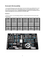
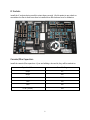
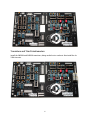
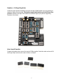
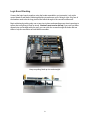
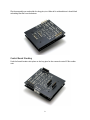
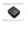
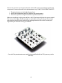
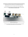
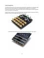
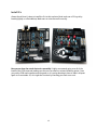
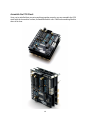
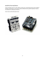
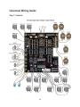
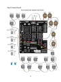
Galilean Moons dual amplitude transmutator DIY ASSEMBLY MANUAL v1.02 Contents Contents.......................................................................................................................................... 2 Introduction .................................................................................................................................... 3 Eurorack Kit Assembly.................................................................................................................... 4 Resistors ..................................................................................................................................... 4 IC Sockets ................................................................................................................................... 5 Ceramic/Film Capacitors ............................................................................................................ 5 Transistors and Trim Potentiometers ........................................................................................ 6 Headers + Voltage Regulator ...................................................................................................... 7 Inter-board Headers ................................................................................................................... 7 Logic Board Stacking .................................................................................................................. 8 Control Board Stacking ............................................................................................................... 9 Control Board Assembly ........................................................................................................... 11 Jack Ground Pins ...................................................................................................................... 14 Install ICs................................................................................................................................... 15 Assemble the PCB Stack .......................................................................................................... 16 Install the Panel and Knobs ...................................................................................................... 17 Universal Wiring Guide ................................................................................................................. 18 Step 1: Controls......................................................................................................................... 18 Step 2: Power/Ground............................................................................................................... 19 2 Introduction Thank you for your interest in/purchase of a hexinverter.net Galilean Moons DIY project! It is my hope that you find this module design a fun addition to your modular synthesizer. This assembly manual will show you how to build your Galilean Moons module in eurorack or how to wire it up for other formats. If you are looking for usage and module specifications, please see the User Manual which can be downloaded from the hex.net project site. Assembling this module in eurorack form requires basic electronics knowledge and soldering ability. If you do not yet have these skills, go practice on some easier projects first! I link to some excellent soldering tutorials in the DIY learning resources section of my project site. A huge thank you to Hannes Pasqualini of papernoise.net for his excellent graphics design and artwork used for this project! (http://papernoise.net). As always, please email me with any tech support or questions you may need answered. I can be reached directly via email at hex[at]hexinverter.net Please read on! --Stacy Gaudreau hexinverter.net Electronics 3 Eurorack Kit Assembly I recommend following the steps outlined here if you haven’t built many modules before. If you are an experienced builder, you could probably just give a read through these steps to catch any possible traps ahead of time. I recommend saving your component lead clippings from the resistors and capacitors to reuse as jack wires in the later steps! Resistors Install the resistors. If you are building a kit with 1% resistors from hex.net, the colour codes are as follows: 100R BROWN BLACK BLACK BLACK BROWN 1k BROWN BLACK BLACK BROWN BROWN 4.7k YELLOW PURPLE BLACK BROWN BROWN 6.8k BLUE GREY BLACK BROWN BROWN 10k BROWN BLACK BLACK RED BROWN 33k ORANGE ORANGE BLACK RED BROWN 47k YELLOW PURPLE BLACK RED BROWN 100k BROWN BLACK BLACK ORANGE BROWN 1M BROWN BLACK BLACK YELLOW BROWN 4 IC Sockets Install the IC sockets, being careful to orient them correctly. I find it easiest to put a book or something else flat on them once they’re installed, then flip the board over for soldering. Ceramic/Film Capacitors Install the ceramic/film capacitors. If you are building a hex.net kit, they will be marked as: Capacitor Value Case Marking 100pF 101 330pF 330 6.8nF 6800 12nF 12n 18nF 18n 0.1uF (100nF) 104 5 Transistors and Trim Potentiometers Install the 2N3904 and 2N3906 transistors, being careful not to overheat. Also install the 4x 100k trim pots. 6 Headers + Voltage Regulator Install the power header (if building eurorack) and the XPAND header if you are planning to expand a Jupiter Storm module. The headers supplied with the kits may look different than pictured. Install the two 6pin ICSP headers too (bottom right) if you plan on upgrading firmware in the future. Inter-board Headers Prepare the headers that connect the stack of PCBs together. Break the male sections off of the longer 40pin sections with a pair of pliers or clippers. 7 Logic Board Stacking Connect the logic boards together using the header assemblies you just made. Look at the control board as well before soldering anything to make sure you’re doing it right. Only four of the headers need to be the long pin kind and reach through to the control board as well. Begin soldering by tacking only one or two pins in place and spending some time inspecting to ensure that everything is lined up nicely. You don’t want to screw this up! If you can’t get them aligned nice and straight with your eyes, you can stick the screws through the holes and use them to help line everything up right while you solder. Keep everything lined up nice and straight! 8 Flip the assembly over and solder the long pins, too. When all is said and done it should look something like this from the bottom: Control Board Stacking Push the female headers into place on the long pins for the eurorack control PCB to solder onto. 9 Take the eurorack control board and set it in place over the female header pins sticking up. Begin soldering only a pin or two, checking to make sure it’s still lined up straight. When satisfied, solder all of the pins. You’re now ready to start the control board assembly! If you’ve been at it awhile, maybe take a break for a bit and come back to it with a fresh mind. This next part is arguably the most difficult and sensitive part of the assembly. You don’t want to mess it up! 10 Control Board Assembly Carefully remove the control board from the rest of the PCB stack you made earlier. Pull it off a bit at a time so as to not damage any pins! Be very careful. Begin the control board assembly by inserting all of the control board parts loosely into the PCB. Screw a nut onto each toggle switch. Place a washer onto each potentiometer. The jacks don’t need their nuts on yet. 11 Remove the protective covering from the panel and install it on the loose-fitting control board components. Screw on the nuts for the potentiometers only. DO NOT SOLDER ANYTHING YET! The potentiometers set the height the panel is at. All the other components follow the height of the potentiometers. This means you have to align and solder the potentiometers first. Make sure everything is sitting nice and flat on the PCB and especially that the pots are seated flat. Once you are happy, flip the assembly over and solder one leg of each pot. Then inspect and reheat any pots that aren’t perfectly flat, pushing them down flat on the PCB with your finger while you reheat the one leg you soldered. Once all of the potentiometers are tacked in place and flush with the PCB, you can go to the next step… 12 Now that the pots are holding the PCB at the right distance from the panel, you can adjust the jacks and switches to the height of the panel. Do so by installing the jack and switch nuts, and finger tightening them to the point that they raise up and sit flush with the panel. Don’t fully tighten the nuts yet! You’re going to need to undo them again shortly. As shown in the image below, the jacks and switches will be raised up off the panel when properly adjusted to the potentiometer height: Make absolutely sure that everything is positioned nicely, then go ahead and start soldering the control components in place! I recommend periodically checking to make sure everything is still seated correctly while you’re soldering. Adjust anything that seems to be seated wrong. 13 Jack Ground Pins You did save your resistor and capacitor lead clippings like I suggested at the beginning, right? Well, now it’s time to put them to use! The Kobiconn jacks require you to run a ground connection for each of them. These are the best and most suitable jacks for the price and this minor inconvenience is well worth it! I bend a little hook shape in each pin and then drop it through the jack pin and into the PCB for each jack. Then you can simply solder them all from the top: …and then flip the board over and solder them all from the bottom. Easy, right?! 14 Install ICs Almost there! Now it’s time to install the ICs in their sockets. Bend each row of IC legs in by bending lightly on a flat tabletop. Make sure to orient them all correctly! Now you are done the actual electronics assembly! I highly recommend going over all of the backs of the PCBs now and making sure there are no shorts or missed soldering points. Once you put the PCB stack together and the panel on, it’s pretty daunting to have to take it all apart again to fix a mistake. So, do it right the first time by checking your work over now! 15 Assemble the PCB Stack Once you’re satisfied that you put everything together properly, you can assemble the PCB stack with the 4x machine screws, 8x standoffs and 4x nuts. It will look something like this when all is done: 16 Install the Panel and Knobs Finally, install the panel. Test the module to make sure it’s all working properly, then install the knobs as a final step! You may need to tune the LEDs before they work as expected. See the User Manual for calibration procedures. Here’s what it will look like when done: 17 Universal Wiring Guide Step 1: Controls 18 Step 2: Power/Ground 19