1
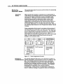
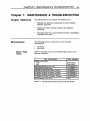
CHAPTER 7. MAINTENANCE & TROUBLESHOOTING
Chapter 7.
MAINTENANCE & TROUBLESHOOTING
Chapter Objectives
Mai ntenance
The infonnatlon In this chapter wUl enable you to:
•
Maintain the system's components to ensure smooth.
efficient operation
•
Isolate and resolve system hardware and software
problems
•
Use this chapter as a quick reference tool for a description
of system error codes
The following system components require periodic
maintenance:
•
•
Spare Parts
Table
189
The Motor
The Drive
Table 7-1 provides a list of recommended spare parts to use
with the AX. system.
Part DescrlDtion
Choice of two drives:
AXH
AXL
Mechanical Screws (6-32 x 1/4)
Universal Mountina Bracket
5-Position Terminal Connector Phoenix
6-Position Terminal Connector, Phoenix
8-Position Terminal Connector, Phoenix
11-Position Terminal Connector, Phoenix
Fan Kit (standard on AXH Drives)
Part Number
AXH-DRIVE
AXL-DRIVE
51-006037-01
53-006007 -01
43-005561-01
43-006606-01
43-006786-01
43-007085-01
AFK
Table 7-1. Recommended Spare Parts for the AX System
190
AX DRIVE USER GUIDE
Motor
Maintenance
You should inspect all mechanical parts of the motor
regularly to ensure that no bolts or couplings have become
loose dUring normal operation. This will prevent minor
problems from developing into more serious problems.
The ball bearings used in the Compumotor-supplied motors
are not sealed against severe environments. but are
permanently lubricated and do not require any maintenance.
You should inspect the motor cables periodically for signs of
wear. This inspection inteIVal is duty-cycle. environment.
and travel-length dependent. You should not apply excessive
tensile force to the cable. Do not bend the cable beyond a oneinch radius of CUIVature during normal operation. Tighten
all cable connectors.
Drive
Maintenance
Troubleshooting
Problem
Isolation
Check that the drive heatsink is free of particles and has a
free flow of air over its entire surface. Enclosures must be
connected to earth ground through a grounding electrode
conductor to provide a low-impedance path for ground-fault
or noise-induced currents. All earth ground connections must
be continuous and permanent.
This section discusses methods to identify. isOlate. and
resolve problems that may occur with your AX Drive.
When your system does not function properly (or as you expect
it to operate), the first thing that you must do is identify and
isolate the problem. When you accomplish this. you can
effectively begin to eradicate and resolve the problem.
Try to determine if the problem is mechanical. electrical. or
software-related. Can you repeat or re-create the problem?
Do not attempt to make quick rationalizations about
problems. Random events may appear to be related. but they
are not necessarily contributing factors to your problem. You
must carefully investigate and decipher the events that occur
before the subsequent system problem.
You may be experiencing more than one problem. You must
solve one problem at a time. Log (document) all testing and
problem isolation procedures. You may need to review and
consult these notes later. This will also prevent you from
duplicating your testing efforts.
Isolate each system component and ensure that each
component functions properly when it is run independently.
You may have to remove your system components and reinstall them component-by-component to detect the problem.
If you have additional components available. you may want
to use them to replace existing components in your system to
help identify the source of the problem.
CHAPTER 7. MAINTENANCE & TROUBLESHOOTING
191
Once you have isolated the problem. take the necessary steps
to resolve it. Refer to the problem solutions contained in this
chapter. If your system's problem persist. contact Parker
Compumotor's Applications Department at (800) 358-9070.
Motor Falls
to Move
Test the motor to see if it has holding torque. If there is no
holding torque. here are some probable causes:
•
There is no AC power.
•
Current selection DIP switches are not set properly (see the
motor current selection table in Chapter 6. Hardware
Reference).
•
There are bad connections or bad cables. Disconnect the
power connector. then use an ohm meter to monitor
continuity between the motor-to-drive cable.
•
The drive may be disabled through software (STI
command).
If the unit has holding torque and the motor shaft still fails to
move. here are some probable causes:
•
The limit switches have been tripped or are faulty. Make
sure that your limit switches are OFF or that the limits are
disabled (LD3 command).
•
The load is jammed. You should hear the drive attempting
to move the motor. Remove AC power from the drive and
verify that you can move the load manually away from the
point of the jam.
•
Indexer parameters are Incorrectly set up. If certain
parameters are out of range or are missing. the motor will
not move when you issue the Go (G) command.
Use R. RA. RB. and RS status commands to detennine what is
preventing the move. Also check A. V. and D commands to
make sure that all the parameters are set properly. The
following are additional troubleshooting techniques:
•
Check the motor for damage. Also check the motor cable
to see if it is damaged or shortened. These conditions may
cause the drive to fault.
•
Ohm the motor and cables to make sure that short-circuits
do not exist between phases or to earth GND. On your most
sensitive scale. the resistance across each motor phase
should be conSistently low (but not zero) and similar to
each other. On your highest scale. the resistance between
motor phases and between each phase and earth ground
should be infinite.
192
AX DRIVE USER GUIDE
Fault LED
Motor Stalls
There is a red FAULT LED located on the connector-side of the
AX dIive. The LED may be activated (illuminated) if one of the
following conditions exists:
•
Shutdown: You commanded the drtve to shutdown. Use
the Sn!) command to tum the drtve on again.
•
Over-temperature: The drive may be overheating
(heatsink temperature is above 149°F (65°C). You may
conSider cooling the drive and/or enclosure. Installing a
fan kit on the drive would help the problem.
•
Short-circuit: A short-circuit exists in the motor current
output. Use an ohm meter to make sure that there is not a
short-circuit between phase A. phase B. or to earth ground.
NOTE: Make sure power has been removed fHd'ore you test
the motor.
•
Brown-out: Check the AC input voltage to make sure that
the drive is receiving more than 95VAC.
A motor stall during acceleration may be caused by one or
more of the following factors:
•
•
•
The torque requirements may be excessive
The acceleration ramp may be too steep
The load inertia and motor inertia may be grossly
mismatched.
Lower acceleration may be required.
If the motor stalls during the constant velocity portion of a
move. the shaft and/or coupler may be damaged or binding
due to improper coupling or excessive motor load.
A stall may occur if the DIP switch setting for the motor
current selection is incorrect. The motor may not be receiving
enough current to operate.
A stall may also be detected in closed loop mode if the encoder
resolution (ER) is not set properly. or if the encoder input
channels (A and B) are reversed.
Motor Falls
to Run at
High
Speeds
The motor may fail to run at high speeds due to the following
factors:
•
It is possible that the motor may not produce enough
torque to move a given load at these velOCities. Check the
torque/speed curve in Chapter 6 and make sure you are
trying to run the motor in the proper range.
•
The indexer can produce pulses faster than the drtve can
make the motor move.
•
The motor may not have the proper load-to-rotor inertia.
The maximum ratio is 10: 1.
CHAPTER 7. MAINTENANCE & TROUBLESHOOTING
Motor Is
Jerky or
Weak
Motor
Overheats
193
Check that there are no mechanical problems at the load
causing highly variable loading condition. Disconnect the
motor from the load and run it without a load connected. Keep
in mind that the motor will run best with a load of equal
inertia; with no load. it will not attain full speed. Tty to
manually tum the motor shaft; this will detenntne if the
motor is maintaining full holding torque. Check the DIP
switches for proper current settings.
If the motor exceeds its maximum motor case temperature
rating. failure will eventually result. Check your DIP Switch
settings to ensure that the current setting is correct for the
motor you are using (refer to Chapter 6. Hardware Reference).
The Standby Current feature (set with the SC or the SCA
command) allows you to reduce the motor current from 13%
to 100% when the motor is not moving. If the motor is hot
after a long period at standstill. check the standby current
with a current probe.
Motor Shaft
Wears
The motor shaft may wear prematurely if there is foreign
material rubbing against the shaft. or if the load is not
coupled properly.
1/0 Switch
If you are having problems using the Trigger (TR). Home (GH)
failure
commands. and the Trigger. Home. CWo CCW and Sequence
Select inputs. you must first check your wiring for proper
installation. Use an Ohm meter to verify proper connection
of the switches and inputs. If the hardware connection seems
correct. you can manually change the input Switches and use
the IS command to verify if the AX recognizes the input
change. The IS command provides a hardware status of the
AX inputs. If the status does not change. check the hardware
settings and wiring.
Remote
Sequencing
(BCD
Inputs)
failure
If you are having problems trying to run sequences from BCD
interfaces. the first thing you must verify is the hardware
interface. Use the Ohm meter to verify proper wiring. Then
use the IS conunand to read the status of the inputs. Change
the input setting and check the Input Status (IS) again to make
sure that the AX recognized the change in the sequence select
input. Make sure that your BCD input is calling the proper
sequences. Check Chapter 6. Hardware Reference. for the
Sequence Select Table. If you have a problem running a
sequence from the remote input, try running the sequence
using the XR command before attempting to run it using BCD
input. Make sure you cycle power or issue a Z command after
you enter an XP8 or XP9 command.
194
AX DRIVE USER GUIDE
Reducing
Electrical Noise
Electrical
Noise
This section discusses the sources and methods of suppressing
electrical noise.
When an AX Drive system is operated in an environment in
which there is an excessive amount of electrical noise. special
care must be taken to eliminate sources of possible noise
interference. Potential sources of electrical noise include
inductive devices such as solenOids. relays. motors. and
motor starters when they are operated by a hard contact.
Compumotor recommends that you mount the AX Drive in a
NEMA enclosure to protect the drive from electrical noise.
For further information on avoiding electrical noise. refer to
the technical data section of the Compumotor Motion Control
Catalog.
Noise suppression devices may be necessary when sources of
electrical noise are connected to the same AC power source or
are in close proximity to electronic eqUipment. You may also
need to install noise suppression devices if you have multiple
drives attached to the same AC power source. Figure 7-1
shows some recommended suppression devices for most small
loads. For best results. install these devices as close as
possible to the inductive load.
AC
r-
DIODE
VARISTOR (MeV)
t
~
~ ~ "--1
1. Can be saved for
both AC and DC
circuits
2. Use 500-1000
ohm for Rand
0.1 - 0.2 microF
@200V
andDC
For DC circuit only
_
Can be used for
both AC and DC
circuits
Figure 7-1. Noise Suppression Devices
You should Install the AX Drive in an enclosure to protect it
Enclosure
Considerations against atmospheriC contaminants such as oll. moisture, and
dirt. The National Electrical Manufacturers Association
(NEMA) has established standards that define the degree of
protection that electrical enclosures provide. The enclosure
should conform to NEMA Type 12 standards if the intended
environment is industrial and contains airborne
contaminants. Proper layout of components is required to
ensure suffiCient cooling of eqUipment within the enclosure.
CHAPTER 7. MAINTENANCE & TROUBLESHOOTING
Sources of
Electrical
Noise
195
NOise-related difficulties can range in severity from minor
positioning errors to damaged equipment from run-away
motors crashing through limit switches. In microprocessorcontrolled equipment. the processor constantly retrieves
instructions from memory in a controlled sequence. If an
electrical disturbance occurs, it may cause the processor to
misinterpret instructions or access the wrong data. This can
be catastrophiC to the program and force you to reset the
processor.
Since electrical noise is not visible, it is very difficult to
detect. Some possible sources are as follows:
•
•
•
•
Power line noise
Externally conducted nOise
Transmitted noise
Ground loops
The following electrical devices are particularly apt to
generate unwanted electrical noise conditions:
•
Coil-driven devices (conducted and power line noise)
•
SCR-ftred heaters (transmitted and power line noise)
•
Motors and motor drives (transmitted and power line
noise)
•
Welders: electric (transmitted and power line nOise)
The AX Drive is capable of delivering 6 amps on a 170V rail to
the motor. This is pulse width modulated at a 20 kHz rate:
consequently. the AX Drive must be considered a source of
electrical noise.
POWER LINE
NOISE
Power line noise is usually easy to resolve due to the wide
variety of line filtering eqUipment that is available to the
motion control industry. Only the most severe electrical
noise problems will require you to use an isolation
transformer. You will have to use line filtering equipment
when other devices connected to the local power line are
switching large amounts of current (especially if the
switching occurs at a high frequency).
Any device that has coils is likely to disrupt the power line
when it is Switched off. Surge suppressors. such as metal
oxide varistors (MOY's) are capable of limiting this type of
electrical noise. A series RC network across the coil is also an
effective means of eliminating the problem (resistance: 500 to
1,000 0; capacitance: 0.1 to 0.2 ~). Coil-driven devices
(inductive loads) include relays. solenoids. contactors.
clutches. brakes. and motor starters.
196
AX DRIVE USER GUIDE
EXTERNALLY
CONDUCTED
NOISE
Externally-conducted noise is similar to power line noise. but
the disturbances are created on signal and ground wires that
are connected to the indexer. This kind of noise can get into
logic circuit ground or into the processor power supply and
scramble the program. The problem in this instance is that
control eqUipment often shares a common DC ground wire
that may be connected to several devices (such as a DC power
supply. programmable controller. remote switches. etc.).
When a source of noise like a relay or solenoid is attached to
the DC ground. it may cause disturbances within the indexer.
To solve the noise problem caused by DC mechanical relays
and solenoids. you must connect a diode backwards across the
coil to clamp the induced voltage kick that the coil will
produce. The diode should be rated a four times the coil
voltage and ten times the coil current. Using solid state relays
is another way to eliminate this problem. See Figure 7-1.
Multiple devices on the same circuit should be grounded
together at a single point.
Furthermore. power supplies and programmable controllers
often have DC common tied to Earth (AC power ground). As a
rule. it is preferable to have the indexer signal ground or DC
common floating with respect to Earth. This prevents sources
of electrical noise that are grounded to Earth from sending
noise into the indexer. When you cannot float the signal
ground. you should make the Earth ground connection at only
one point.
In many cases. optical isolation may be required to
completely eliminate electrical contact between the indexer
and a noisy environment. Solid state relays provide this type
of isolation.
TRANSMITTED
NOISE
Transmitted nOise is picked up by external connections to the
indexer. and in severe cases can attack an indexer with no
external connections. The indexer enclosure will typically
shield the electronics from this. but openings in the enclosure
for connections and front panel controls may leak. As with
all electrical eqUipment. the indexer chassis should be
scrupulously connected to Earth to minimize this effect.
When high current contacts open. they draw an arc. producing
a burst of broad spectrum radio frequency noise that can be
picked up on an indexer limit switch or other wiring. Highcurrent and high-voltage wires have an electrical field around
them. and may induce noise on signal wiring. espeCially when
they are tied in the same wiring bundle or conduit.
CHAPTER 7. MAINTENANCE & TROUBLESHOOTING
197
When this kind of problem occurs, it is time to think about
shielding signal cables or isolating the signals. A proper
shield surrounds the signal wires to intercept electrical fields,
but this shield must be tied to Earth to drain the induced
voltages. At the very least, wires should be run in twisted
pairs to limit straight line antenna effects.
Most Compumotor cables have shields tied to Earth, but in
some cases the shields must be grounded at installation time.
Installing the indexer in a NEMA electrical enclosure ensures
protection from this kind of noise, unless noise-producing
equipment is also mounted inside the enclosure. Connections
external to the enclosure must be shielded.
Even the worst noise problems in environments near 600 amp
welders and 25kW transmitters have been solved using
enclosures, conduit, optical isolation,and single point ground
techniques.
GROUND
LOOPS
Ground Loops are the most mysterious noise problems. They
seem to occur most often in systems where a control computer
is using RS-232C communication. Symptoms like garbled
transmissions and intermittent operation are typical.
The problem occurs in systems where multiple Earth ground
connections exist, particularly when these connections are
far apart.
Suppose an AX is controlling an axis, and the limit switches
use an external power supply. The AX is controlled by a
computer in another room. If the power supply Common is
connected to Earth, the potential exists for ground loop
problems. This is because most computers have their RS232C Signal common tied to Earth. The loop starts at the AX
limit switch ground, goes to Earth through the power supply to
Earth at the computer. From there, the loop returns to the AX.
through RS-232C signal ground. If a voltage potential exists
between power supply Earth and remote computer Earth,
ground current will flow through the RS-232C ground creating
unpredictable results.
The way to test for and ultimately eliminate a ground loop is
to lift or cheat Earth ground connections in the system until
the symptoms disappear.
198
AX DRIVE USER GUIDE
Defeating
Noise
The best time to handle electrical noise problems is before
they occur. When a motion control system is in the deSign
process, the designer should consider the following set of
gUidelines for system wiring in order of importance:
1. Put surge suppression components on all electrical coils:
ReSistor / capacitor fUters, MOVs, Zener and clamping
diodes.
2. Shield all remote connections, use twisted pairs. Shield
should be tied to Earth at one end.
3. Put all microelectrical components in an enclosure. Keep
noisy devices outside, watch internal temperature.
4. Ground Signal common wiring at one point. Float this
ground from Earth if possible.
5. Tie all mechanical grounds to Earth at one point. Run
chassis and motor grounds to the frame, frame to Earth.
6. Isolate remote Signals. Solid state relays or opto isolators
are recommended.
7. Filter the power line. Use common RF filters, isolation
transformer for worst case.
A noise problem must be identified before it can be solved.
The obvious way to approach a problem situation is to
eliminate potential noise sources until the symptoms
disappear, as in the case of ground loops. When this is not
practical, use the above gUidelines to shotgun the installation.
References
Information about the equipment referred to in this chapter
may be obtained by calling the numbers listed below:
•
Corcom line filters, (312) 680-7400
•
Opto-22 optically isolated relays, (714) 891-5861
•
Crydom optically isolated relays, (213) 322-4987
•
Potter Brumfield optically isolated relays, (812) 386-1000
•
General Electric MOVs, (315) 456-3266
•
Teal ElectrOnics Corporation-specializing in power line
products, (BOO) 888-TEAL.
CHAPTER 7. MAINTENANCE & TROUBLESHOOTING
RS-232C
Communications
Troubleshooting
199
Procedures for troubleshooting three-wire RS-232C
communications are as follows:
1. For single-axis applications. make certain the transmit
(pin 2) of the host is wired to the receive ( pin 1) of the AX
unit. Also. make sure that the receive (pin 3) of the host is
wired to the transmit (pin 2) of the AX unit.
ny switching the receive and transmit wires on
either the host or peripheral if you faU to get any
communication.
N01E:
2. If you have a daisy-chained system. make sure the
following connections are made:
•
•
•
•
Transmit (AX. pin 2) connected to receive (AX pin 1) of
the successive AX units In the chain
COM (AX pin 3) is connected between AX units and to
GND (pin 7) on the host
Transmit (AX pin 2) of the last AX unit in the chain
connected to the receive (pin 3) on the host
Transmit (pin 2) of the host connected to the receive
(AX. pin 2) on the first AX unit in the chain
3. Some computer serial ports require handshaking.
Typically. you can disable the handshaking function by
jumpertng RrS to CTS (usually pins 4 and 5) and DSR to
om (usually pins 6 and 20). Refer to your computer or
terminal user gUide for exact instructions.
4. Configure the host and peripheral to the same baud rate.
number of data bits. number of stop bits. and parity.
5. If you receive double characters (for instance. if you type A
and receive AAl. your computer is set to half-duplex.
Consult your computer or terminal emulator user manual
for Instructions on how to change the set-up to full-duplex.
6. Use DC common or signal ground as your reference. 00
Nar use earth ground.
7. Cable lengths should not exceed 50 ft. unless you are using
some form of line driver. optical coupler. or shield. As
with any control signal. be sure to shield the cable to earth
ground at one end only.
8. To test your terminal or terminal emulation software for
proper 3-wire communication. unhook your peripheral
device and transmit a character. You should not receive
an echoed character. If you do. you are in half-duplex
mode. Jumper the host's transmit and receive lines and
send another character. You should receive the echoed
character. If not. consult the manufacturer of the host's
serial Interface for proper pin-outs.
200
AX DRIVE USER GUIDE
Returning The
System
If you must return your AX system to effect repairs or
upgrades. use the following steps:
1. Get the serial number and the model number of the
defective unit. and a purchase order number to cover
repair costs in the event the unit is determined by Parker
Compumotor to be out of warranty.
2. Before you ship the drive to Parker Compumotor. have
someone from your organization with a technical
understanding of the AX system and its application
include answers to the following questions:
•
•
•
•
•
•
•
•
•
•
•
•
What is the extent of the failure/reason for return?
How long did it operate?
How many units are still working?
How many units failed?
What was happening when the unit failed (i.e ..
installing the unit. cycling power. starting other
equipment. etc)?
How was the product configured (in detail)?
What. if any. cables were modified and how?
With what equipment is the unit interlaced?
What was the application?
What was the system sizing (speed. acceleration. duty
cycle. inertia torque. friction. etc.)?
What was the system environment (temperature.
enclosure. spacing. unit orientation. contaminants.
etc.)?
What upgrades. if any. are required (hardware.
software. user guide)?
3. Call Parker Compumotor for a Return Material
AuthOrization IRMA) number. Returned products cannot
be accepted without an RMA number. The phone number
for Parker Compumotor Applications Department is (800)
358-9070.
4.
Ship the unit to:
Parker Compumotor Corporatlon
5500 BUSiness Park Drive
Rohnert Park. CA 94928
Attn: RMA # xxxxxxx