1
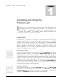
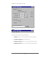
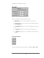
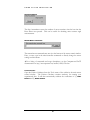
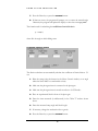
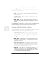
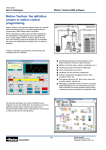
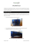
2
Team
ENME 414: COMPUTER-AIDED DESIGN
Friction Apparatus
Guide to the
Friction Lab
ENME 414: COMPUTER-AIDED DESIGN
Guide to the Friction Lab
Team 2 consists of:
Edward Chang • Elaine Cheong • Anthony Gino • Thomas Griffith • Phil Rowland
December 13, 1999
Table of Contents
Introduction
C H A P T E R
i
1
Installation
1
Friction apparatus assembly
1
Computer-controlled motor
1
Photogate and photogate timer
2
Magnetic protractor
3
Friction lab software
3
Using the Software
3
Motor Control
3
Friction Calculator
5
Troubleshooting and Other Tips
8
Tool tips
8
Port settings
9
Resetting and restarting
9
Summary
C H A P T E R
10
2
Computer-Controlled Motor
11
Programming Environment
12
Microsoft Visual Studio 6.0
12
Microsoft Visual Basic 6.0
12
Features of the Friction Lab Software
13
Future Development
14
G U I D E
I C O N
K E Y
1 Valuable information
:
Hardware
information
< Software information
M Important
instructions
« References
T O
T H E
F R I C T I O N
L A B
Introduction
T
his guide is aimed at users of the friction lab and future developers or
maintainers of the friction lab software. The first chapter contains
information on setting up the hardware, using the software to complete a
friction lab, and troubleshooting the software and hardware. The second
chapter highlights the development process, special features of the software, and tips
on future code development and maintenance.
The icons illustrated in the key on the left will be used to point out important sections
or tips in the user manual.
i
G U I D E
T O
T H E
F R I C T I O N
L A B
1
Chapter
Installing and Using the
Friction Lab
I
n this chapter, you will learn how to install the friction lab hardware, use the
accompanying software, and troubleshoot problems. Use this chapter as a
reference guide to accompany the instructions for the experiment that your
professor has provided. The following chapter contains information on
developing and maintaining the friction lab software.
Installation
The friction lab is composed of several parts: (1) friction apparatus assembly, (2)
computer-controlled motor, (3) photogate and photogate timer, (4) magnetic
protractor, and (5) friction lab software. You will also need a PC (Pentium® 90MHz
or higher microprocessor; VGA 640x480 or higher-resolution screen supported by
Microsoft Windows; 24MB RAM for Windows 95, 32MB for Windows NT;
Microsoft Windows NT 3.51 or later, or Microsoft Windows 95 or later) and the
floppy disk containing the friction lab code.
1
:
Friction apparatus assembly
All of the friction lab hardware is mounted on the Plexiglas baseplate. The friction
apparatus assembly consists of an aluminum friction plane frame that holds
experimental boards made of various materials on which to conduct your experiment.
A plastic board and a wooden board are included with the friction lab. Boards of other
materials may easily be created by simply cutting a sheet of the desired material and
drilling holes in the corresponding locations. You may then mount the board on the
screws located on the friction plane framework. The aluminum roller framework is
located underneath of the friction plane frame. The roller framework moves back and
forth and changes the angle of the friction plane.
Computer-controlled motor
The computer-controlled motor turns a motor shaft, which moves the motor plate
(attached to the roller framework) back and forth on the slide rails. The motor
controller housing is mounted next to the motor on the baseplate. The motor is
powered by a transformer, which is also mounted on the baseplate.
1
G U I D E
T O
T H E
F R I C T I O N
L A B
MVerify that all of the cables are connected properly while the power is OFF:
1. The motor serial port cable (connects to TX, RX, and GND on the motor
controller housing) should be plugged into COM1 or COM2 of the
accompanying computer.
2. The main motor cable has an MS-type connector on the motor end, and
five leads with screw terminals on the drive end (located on the motor
controller housing).
3. The position sensor cable should connect the plug on the motor controller
housing to the encoder socket on the motor.
4. Make sure the limit switches (two small roller switches located at either end of
the slide rails) are connected properly. Each roller switch should have two
wires: one on the main terminal, and one on the NC (normally closed)
terminal. These wires should be kept away from the roller assembly's path.
Both black wires should be connected to GND on the motor controller
housing. The white wires are connected to CW LIMIT (clockwise) and CCW
LIMIT (counter-clockwise). These limits prevent clockwise or counterclockwise movement when the switches are pressed (they are normally closed).
These fail-safe switches prevent you from accidentally damaging the motor
when the motor plate reaches either end of the slide rails.
5. The transformer provides power, and it should be connected to the AC
terminals on the motor controller housing. When you provide power, the
status LEDs on the motor controller housing should read "00."
«Documentation and other information on the Compumotor Plus™ can be found at
http://www.compumotor.com/.
:
Photogate and photogate timer
The photogate is mounted on a metal rod on top of the friction plane. The photogate
timer is used to measure the time it takes for an experimental block to pass through the
photogate.
MVerify that all of the cables are connected properly:
1. When in use, the photogate should be connected to the photogate timer via
the plastic RJ-11 (standard household telephone jack) connector.
2. The photogate timer should be powered via the AC plug.
3. The photogate timer should be turned on by setting it to GATE mode. Clear
or zero the timer using the RESET switch.
2
G U I D E
T O
T H E
F R I C T I O N
L A B
«More information on the PASCO photogate and photogate timer can be found at
http://www.pasco.com/.
Magnetic protractor
The magnetic protractor is removable and can be used to measure the angle of the
friction plane.
<
Friction lab software
The friction lab software (executable and source code) is provided on the
accompanying floppy disk. It is also available on the ENME414 Fall 1999 Team 2
website at http://www.isr.umd.edu/~zhang/.
MTo install on a PC with Microsoft Windows:
1. Insert the floppy disk into drive A: (floppy disk drive).
2. Click on the Start Menu Button and select Run…
3. Type: a:\setup.exe
4. Follow installation instructions.
MTo run the software:
1. Make sure the motor is powered.
2. Click on the Start Menu Button and select the Programs|Friction Lab
directory.
3. Click on Friction Lab.
Now you are ready to learn how to use the friction lab software!
1
Using the Software
The software consists of two main windows: (1) Motor Control and (2) Friction
Calculator.
Motor Control
The motor control window is the main window of the program. You will see the
toolbar, controls for motor settings, motor movement buttons, step accumulator,
and controls for manual motor command.
3
G U I D E
T O
T H E
F R I C T I O N
L A B
Toolbar
The toolbar menus contains several useful commands:
•
File|Exit prompts you to close the program and all associated windows.
•
Tools|Friction Calculator starts the calculator tool.
•
Options|Port Properties… allows you to change the COM port settings.
•
Help|About Friction Lab… shows you more information on the program.
3
G U I D E
T O
T H E
F R I C T I O N
L A B
Motor Settings
The motor settings frame contains several useful controls:
•
Normal Mode allows you to preset the distance to move the motor.
•
allows you to move the motor continuously until you
press the Stop button.
Continuous Mode
• The Acceleration slider allows you to set the acceleration of the motor in
rps2.
• The Velocity slider allows you to set the velocity of the motor in rps.
• The Distance slider allows you to set the distance to move the motor in
rotations.
Motor Movement Buttons
The motor movement buttons cause the ramp to move up, move down, or stop.
4
G U I D E
T O
T H E
F R I C T I O N
L A B
Step Accumulator
The Step Accumulator counts the number of motor rotations since the last time the
Reset button was pressed. This can be useful for obtaining more accurate angle
measurements.
Manual Motor Commands
The manual motor command entry area is at the bottom of the motor control window.
Here, you may type in the microcontroller commands to directly change the motor
settings and movement.
«For a listing of commands and usage descriptions, see the Compumotor Plus™
documentation at http://www.compumotor.com/manuals/1020/CPlus.htm.
Friction Calculator
Open the Friction Calculator from the Tools menu of the toolbar in the main motor
control window. The Friction Calculator contains textboxes for entering your
experimental data. It will then automatically calculate the coefficients of (1) static
friction and (2) kinetic friction.
5
G U I D E
T O
T H E
F R I C T I O N
L A B
Coefficient of Static Friction
The friction calculator can automatically calculate the coefficient of static friction. To
use:
1. Lower the ramp (using the buttons in the Motor Control window) to a small
angle.
2. Place an experimental block near the top edge of the friction plane.
3. Raise the ramp until the block starts sliding.
4. Experiment to find the exact ramp position where the block starts to slide.
5. Measure the angle of the ramp using the magnetic protractor.
6. Enter the angle into the textbox shown above.
6
G U I D E
T O
T H E
F R I C T I O N
L A B
7. Press the Enter key or press the Calculate button.
8. If there are errors, the program will prompt you to correct the entered angle.
Otherwise, the program will update the display to show the correct µ_static.
The formula used for calculating the coefficient of static friction is
µ s = tan(θ )
where θ is the angle at which sliding starts.
Coefficient of Kinetic Friction
The friction calculator can automatically calculate the coefficient of kinetic friction. To
use:
1. Raise the ramp (using the buttons in the Motor Control window) to an angle
where the block slides at a comfortable velocity.
2. Make sure the photogate timer is connected to the photogate.
3. Make sure the photogate timer is turned on and set to GATE mode.
4. Place an experimental block in front of the photogate.
5. Enter the time measured (in milliseconds) in the "delta T" textbox shown
above.
6. Enter the measured ramp angle and block length.
7. If necessary, change the acceleration due to gravity.
8. Press the Enter key or press the Calculate button.
7
G U I D E
T O
T H E
F R I C T I O N
L A B
9. If there are errors, the program will prompt you to correct the entered data.
Otherwise, the program will update the display to show the correct µ_kinetic.
The formula used for calculating the coefficient of kinetic friction is
µ k = tan(θ ) −
( ∆dt )2
2 gd cos(θ )
where θ is the angle used for the experiment, g is the acceleration due to gravity, d is the
length of the block, and ∆t is the time it takes for the block to move one block-length.
1
Troubleshooting and Other Tips
Tool tips
Your first source of help should be the tool tips. These small pop-up boxes appear
when you place your mouse cursor over an object in any of the friction lab program
windows. They contain useful tips and information on each object.
8
G U I D E
T O
T H E
F R I C T I O N
L A B
Port settings
If the motor is not working, make sure your COM port settings are correct. The
default setting for the motor is COM1, 9600 bps, 8N1, no flow control. From the
Options menu on the toolbar, select Port Properties… Try using a different COM
port.
Resetting and restarting
If the motor is not working, and changing the COM ports does not work, try restarting
the program.
If that does not work, try resetting the motor by removing the Compumotor Plus logo
cover on the motor controller housing and pressing the + and - buttons shown below:
P
I
+
V
D
-
If the soft reset does not work, try turning the motor off (unplug it), waiting a few
seconds, and turning it back on.
9
G U I D E
T O
T H E
F R I C T I O N
L A B
Summary
Using the friction lab is straightforward. Once you have connected all of the cables
properly, the software makes it very easy to control the height of the ramp so that you
can take measurements for various experiments involving friction.
10
2
Chapter
Developing and
Maintaining the Friction
Lab Software
I
1
n this chapter, you will learn how the friction lab software was developed using
the Compumotor Plus™ and Microsoft Visual Studio™ 6.0. This will give you
some background if you choose to maintain or further develop the software.
This chapter also includes ideas on possible improvements and other
modifications to the friction lab.
:
Computer-Controlled Motor
As described in the previous chapter, the friction lab uses the Compumotor Plus™
computer-controlled motor to move the friction plane.
In the documentation, we discovered several useful Compumotor Plus™ features:
•
Non-continuous move mode.
•
Non-interactive programming mode.
This is useful for automatic
programming, so that the user does not need to manually type in
commands. However, we did not use this in the final version of our
program.
•
Programmable delays. This is useful for timing, so that the user does not
need to calculate wait times for motor movement and determine when to
begin the next command. However, we did not use this in the final
version of our program.
•
Program branching.
This allows the programmer to specify a
discrete number of rotations for the motor shaft to move so that the user
does not have to time the stopping distance of the motor precisely.
The motor controller contains useful programming
constructs such as branching which can be used to create complex, user-
11
deterministic programs. However, we did not use this in the final version
of our program.
<
Programming Environment
We chose to use Microsoft Visual Studio 6.0, so that we could generate easy-to-use
programs with the Windows look-and-feel. Specifically, we chose to program in Visual
Basic for rapid prototyping.
Microsoft Visual Studio 6.0
Microsoft Visual Studio comes with several useful tools that we used in the
development of the friction lab software:
•
Graphics Editor.
•
Package & Deployment Wizard.
•
Help Workshop.
Allows you to create and edit icons. Access this from
Microsoft Visual C++. Click on Insert|Resource… and select Icon.
Allows you to create an executable
distribution for installing your program and associated files. Available in
the Visual Studio 6.0 Tools installation.
Although we did not actually use this in the final version
of the program, this utility allows you to compile Microsoft Help files.
Available in the Visual Studio 6.0 Tools installation.
Microsoft Visual Basic 6.0
We discovered several useful Visual Basic features, tools, and sample code:
•
MSComm.
•
Object Properties.
•
Object Methods.
The serial communication control, called MSComm, is a
much-improved interface to the serial port of the PC. It is quite easy to
use the MSComm event handler to respond to receive and transmit
signals. It is also very straightforward to set up the baud rate, parity
checking, stop bits, flow control, and serial port number and to open and
close the port.
You can easily specify the property of any object,
including buttons, textboxes, toolbars, etc. An especially useful feature is
the ToolTip property.
The user interface in Visual Basic 6.0 is straightforward
to create once the programmer becomes familiar with the Visual Basic
environment. You specify the actions that a button or menu should
perform by double- or right-clicking on the object icon and filling in the
generated code blocks.
12
•
Online Documentation.
The online documentation is very helpful in
learning how to create and specify new features in the user interface.
Other useful Visual Basic 6.0 controls and tools that we found but did not use in the
final version of the program include:
•
Timer. To keep track of time within the program without implementing a
separate clock utility.
•
Icon level raising.
•
Debug output.
Toggles the icons of a program feature with
complementary states.
Write error messages or other debug statements to a
Visual Basic debug window without altering the appearance of the user
interface.
We designed features to implement in our project software and hardware through
further experimentation with the motor commands and Visual Basic software.
<
Features of the Friction Lab Software
We have implemented many features in the graphical user interface to make it
maximally accessible for future students, teachers, and programmers:
•
Serial communications control.
•
Debug output.
•
Coarse- and fine-grain control.
•
Online help.
The program opens a serial connection
and enables the user to write various microcontroller commands to the
serial port, either manually or with automatic buttons. The port number
and other COM settings can be changed on-the-fly using the Port
Settings feature.
Acknowledgements from the microcontroller are read in
and written to the debug output of the Visual Basic IDE (integrated
development environment).
The graphical user interface includes 3
sliders (horizontal scrollbars) for increasing or decreasing the acceleration,
velocity, and travel distance of the motor. The user can switch between
continuous and non-continuous (default) movement.
We have added Tool Tips to all buttons and sliders. If the
student does not know how to use a particular feature of the software,
s/he can simply hold the mouse pointer over the feature, and a Tool Tip
box describing the feature functionality will appear.
13
1
•
Menu options.
•
Automated calculation.
We have added a menu bar to the program. The menu
bar can be used to gain access to other features not visible on the main
screen. We have implemented an About dialog box which provides a
summary of the project software.
A Friction Calculator tool is available which
allows students to type in the values of experimental data. The program
automatically computes the corresponding coefficients of friction (static
and kinetic).
Future Development
We have considered several advanced features, which are quite complex and should be
considered for possible implementation in the future:
•
This feature will allow students to calibrate the home
and end positions of the motor so that the program can automatically
calculate the angle of the ramp. This is accomplished by pre-determining
the relative distances and angles of the motor plate and friction ramp,
respectively. The step accumulator (already implemented) may be useful
here.
•
Data storing and graphing.
•
Automated sensor reading.
Angle calibration.
Students can enter multiple data sets, and the
software can save experimental and calculated data to a file for graphing
with Microsoft Excel or another spreadsheet utility. Students will then be
able to see how material and system properties change the amount of
energy lost to friction. A more advanced way of implementing this would
be to learn how to use OLE (object linking and embedding) to embed
Excel capabilities within the friction apparatus software so that students do
not have to use another program to graph their data.
The photogate timer is connected to the
photogate via an RJ-11 connector (standard U.S. household telephone jack
size). It may be possible to find another plug and splice the wires to
connect to a parallel port header. This can then be attached to the PC so
that the software can automatically read the scan the sensors and calculate
the velocity of the block as it slides through the gate. However, if this does
not work, photogate sensors can be purchased and installed along the sides
of the friction plane. Wires to the sensors could then be connected to the
parallel port header. Note that using the serial port (of the remaining ports
on the PC), instead of the parallel port for obtaining data from the sensors,
would not be the best idea. This approach would require a second
14
implementation of serial communications in hardware, in addition to the
sensor data acquisition implementation.
Since software is never set in stone, future developers can always add new features as
they think of them. Visual Basic allows programmers to add these new features easily.
15