Download Print - Docket Alarm
Transcript
Motion Toolbox” User.Guide A Library of LabVlEW Virtuai Instruments for Motion Control Developed by Snider Consultanfs, Inc. compumotor Division Parker Hannifin Corporation pin 884113929-01 A ABB Inc. EXHIBIT 1013 Page Page 1 1 of of 113 113 RGBINSPOOO17944 Motion Toolbox" User Guide A Library of LabVIEW® Virtual Instruments for ’ Motion Control Version 1.0 March 1994 Part Number 88—013929—O1 \% C g§ .':u\,mi © Copyright 1994 Snider Consultants, Inc. All Rights Reserved. ‘§£:";~'ra=-—\«W,*.4g»_ -:~._ {i 2 f 113 113 Page Page 2 of l('\)’GBlNSP00017945 eI,!‘« I i ,c <c I :"‘fl.-~M“ ”’=1. Warnings Because software controls machinery, test any software control for safety under all potential operating conditions. Failure to do so can result in damage to equipment and/or serious injury to personnel. Limited Warranty Compumotor warrants that the software will perform substantially in accordance with the accompanying material for a period of ninety (90) days from the date of receipt. Any implied warranties on the software are limited to ninety days. Some states do not allow limitations on duration of an implied warranty, so the above limitation may not apply to you. I .4 “’'E; 2.-~«I‘' 1n,.p' flyg‘” > Compumotor's entire liability and your exclusive remedy shall be at Compumotor's option, either (a) return the price paid or (b) replacement of the software that does not meet Compumotor's Limited Warranty and that is returned to Compuznotor with a copy of your receipt. This limited warranty is void if failure of the software has resulted from accident, abuse, or misapplication. Any replacement of software will be warranted for the remainder of the original warranty period or thirty (30) days, whichever is longer. Compumotor disclaims all other warranties, either expressed or implied, including but not limited to implied warranties of merchantability and fitness for a particular purpose, with respect to the software and the accompanying written materials. This limited warranty gives you specific legal rights. You may have others which vary from state to state. J-e1,':‘.fis’~;?t3x£ITrZ»7 ii 3,.If-A s éz In no event shall Compnmotor or its suppliers or distributors be liable for any damages whatsoever (including, without limitation, damages for loss of business profits, business interruption, loss of business information, or other pecuniary loss) arising out of the use or inability to use this Conzpinnotor product, even if Compnmotor has been advised of the possibility of such damages. Bewiwe some states do not allow the exclusion of limitation for liability for consequential or incidental damages, the above limitation may not apply to you. IE ;.i',«e_-» Page Page 3 3 of of 113 113 RGBINSP00017946 Copyright Under copyright laws, this publication may not lie reproduced or transmitted in any form, electronic or mechanical, including photocopying, recording, storing in an information retrieval system, or translating, in whole or part, without the l1 2, l prior written consent of Snider Consultants, Inc. Trademarks Motion Toolbox is a trademark of Snider Consultants, inc. Motion Architect is a registered trademark of Parker Hannifin Corporation, Coxnpumoror Division. LabVIEW is a registered trademark of National Instruments Corporation. Windows is a registered trademark of Microsoft Corporation. Page Page 4 4 of of 113 113 RGBINSP00017947 /' Table of Contents Introduction............... ......... Overview.......... ..............................l installation .................................................. .1 Package Contents .. ... . ..... .. ...... . ............ 1 Software Requirements.... .......................... 2 Pre-Installation Procedure .......................... 2 installation Procedure ... . .............. .... 3 Motion Toolbox Registratlom... ..... 3 Getting Started......... ...... .... ......... .......... ...... 3 Related Publications .............................................................. 5 Using Motion Toolbox Device Communication ............................................................. 7 Common Vl inputs and Outputs... ......... 7 Motion Toolbox Error Handling..... ........... ........ 9 6000 Controller Error Handling ...................... .. 9 Reducing Vl load Time................................. 9 imer Resolution ....... ... ............. 1 0 Vi Labeling Conventions ........................... 10 Bold and Non-bold ............ ..1O Default Inputs ........................................................... 10 Counter 8: Timer .... Counter 8: Timer Vl Descriptions.................. Configuration ............ 11 Start 6000 Timer ....... ... . ..... . . ............ 11 Stop 6000 Timer ........... 12 Configure Encoder input as Cou ter ............. .. 12 Reset 6000 Hardware Counter .................................... 13 Configuration VI Descriptions ......315 .................................... 15 Set Motion Scaling Factors.. ...... . . .. ........ 15 Set Path Scaling Factors ....o . .... ... .. 16 Enable Scale Factors ........... . 17 Set Participating Axes ................... 17 Configure Command Control .. 18 Set Continuous/Preset Mode .................... .. 19 Set Absolute/Incremental Mode .. . .... .. .... 19 Set Drive Resolution ..... ....... . ..... ... . .. . ... . ...... 20 Set Drive Fault Level ....................... .. Z0 Enable Drive ..................... . .............. . . 21 Configure Feedrate Override .. ........... .. 22 Enable Feedrate Override ............................... . 23 Set Encoder Resolution .. . .... . ...... .......... ..... 23 Set Encoder/Motor Step Mode ..................................... 24 Page 113 Page 55 of ggé}N%Pooo1794s Configure Homing .................................................... .. 24 Configure Position Maintenance ................................. .. 26 Enable Position Maintenance ..................................... .. 27 Configure Stall Detection ..... .. .. 2'.’ Enable Stall Detection ................... .. 28 Set Pulse Width ....................................................... .. 29 Device Communication 31 Device Communication ‘J! Deacriptions..... Open AT64-00 .................... .. 31 Open 6200.. ................................................... .. 32 Close Device ........................................................... .. 33 Set Default Addr/Port. 33 Reset 6000 . .. . .. . . . .. . . . . .. . . . . . . . .. 33 Set Error Action ....... .. 34 Set Parameter Precision 34 Set AT6400 Polling Parameters ........... .. 35 Set 6200 Polling Parameters 36 Send 6000 Block .................................. .. 36 Receive 6000 Block .............................. .. 37 Query 37 Download 6000 File... ................................... 38 Enable Communications Tracing ........................ .. V5 38 Configure Communications Tracing 39 Delete Trace File ................................................ .. 40 Command Snooper .................................................. .. 40 Fast Status Vls. ....... ...... Fast Status Vi Descriptions... ......................................... .. 41 Get Fast Status ............................................ .. 41 Set Motor Pos Local Scallng..... .. 43 Set Encoder Pos Local Scaling .. ............ .. 43 Set Velocity Local Scaling ...... .. 44 Motor Position Parse ................ .. .. 45 Encoder Position Parse ............ .. .. 45 Velocity Parse ................ .. .. 46 Pas. Captured Status Parse .................... .. .. 47 Command Error Parse ............................ .. .. 47 Configuration Status Parse ..... .. 48 Encoder Feedback Status Parse ................................. .. 48 Hard Limit Status Parse ............................................ .. 49 Motion Status Parse .......... 49 Soft Limit Status Parse . . . . . . . . . . . .. 50 System Status Parse ..... .. 51 Drive Status Parse ..................... .. . 52 User Status Parse ......................................... .. 53 Page Page 6 6 of of 113 113 RGBINSP00017949 Timer Status Parse ................................................... .. 53 Analog Input Parse ..................................... .. 54 ’ Limit Input Status Parse.. ‘ Joystick Status Parse ........ V’ Digital Output Status Parse .. ............................ .. 54 . . 55 .......................... .. 56 Other Input Parse ....................................... .. 56 . ‘ * Digital Input Parse .................................................... .. 57 I10 8: Limit I/O & Limit VI Descriptions .................................................... .. 59 Set 6000 Input Active Level .. .. 59 Enable 6000 Inputs ............ .. 60 Set 6000 Input Function . . . . . . . . . . . ......... ...... .. 61 Enabie 6000 Input Functions .... .. .. 62 Set 6000 Input Debounce ‘lime .. ............. .............. 62 Set 6000 Output Active Level .. ............................ .. 63 Enable 6000 Outputs .. . . . . . . . . . . . . . .. .. 64 Set 6000 Output Function . . . . . . . . . . . . . . . . . . . . . .. 64 Enable 6000 Output Functions . .............. .. 65 Set 6000 Output States ........ .. 66 Configure Hard Limits . . . . . . . .. .. 67 Enabie Hard Limits ...................................... .. . 67 Configure Soft Limits. .. 68 Enable Soft Limits ............... .. .. 69 Enabie Analog Input Override .............................. .. . 69 Set Analog Input Override Voltage ...................... .. . 70 Define 6000 User Status ............. .. 71 Enable 6000 User Status 72 Jogging & Joystick Jogging and Joystick VI Descriptions ...................................... .. 73 Enable Jog Mode . . . . . . . . . . . . . . . . . . . . . . . .. 73 Set Jog Velocity Low . .. . . . . . . . . . . .. . . .. 74 Set Jog Velocity High ....... .. 74 Set Jog Acceleration 75 Set Jog Deceleration ......................... .. 75 Enable Joystick Mode ........................ .. 76 Set Joystick Velocity l.ow.... 76 Set Joystick Velocity High ............ .. 77 Set Joystick Acceleration .............. .. 77 Set Joystick DeceIeration..... . .. 78 Setup Joystick Electronics ....................... .. 78 Set Joystick Analog Inputs ....................... .. . 79 Set Joystick Zero ..................................................... .. 80 iii ~-='.,2“»4‘cr”;:fP£7 Page Page 7 7 of of 113 113 RGBINSP00017950 r 1 .3 Miscellaneous Vls Miscellaneous Vi Descriptions ............................................... .. Numeric Event ................................... .. Boolean Event Boolean Transition ................................................... .. 81 81 82 83 Motion Vls Motion Vl Descriptions ......................................................... .. 85 Initiate Motion.... 85 Stop Motion.... ............... .. 86 Kill Motion ............... .. 87 Set Velocity Set Acceleration . Set Deceleratiun ...................................... 89 Set Direction .. 89 Go Home ....................................... .. 90 Initiate Linear lnt. Motion ............................... .. .. 90 Set Position ..................... .. .. 91 Wait for Move Complete .......................... .. .. 92 Run Path ............................................... .. .. 92 Set Path Vel & Acc.. .. 93 Run Program ........................................................... .. 93 {P240 Display Vls . .... .... .......................................... ..95 RP240 Vl Descriptions................................................. .. Write Text to RP240 ......... .. Display Variable on RP240 ....... .. Set RP240 LED States .. . . . . . . . . . . . .. Clear RP240 Display .. Position RP240 Cursor... ............................ Enable RP240 Jog Mode .......................... Set RP24O 95 95 96 96 97 9'] 98 99 Variable & Transfer VIs.. .................................. ...... ..101 Variable 8: Transfer VI Descriptions ...................................... .. 101 Set Numeric Van'able........ .. 101 Set Binary Variable.... .. .. ................................. .. 102 Set Binary Variable by Byt . ................................. .. 102 Set String Variable ........... .. .. 103 Transfer Numeric Variable ....................... .. . 103 Transfer Binary Variable .......................... .. . 104 Transfer String Variable . .. . . . . . . . . . .. 104 Transfer Captured Positions ....................... .. 105 Miscellaneous Transfers .......................................... .. 106 “{P’Wg‘-*,'f.=K Page Page 8 8 of of 113 113 RGBINSP00017951 -anun.........u«.uua-u-.-oou.....au..........-o .... oucnruunoooo Motion Toolbox Error Codes ...................................... ..107 Technical Support .................... .. Compumotor Bulletin Board Service. Systems Integration and Consulting .................................... .. 108 Motion Toolbox VI Index (alphabetican 109 ._'-»;:“,M~ f 113 113 Page Page 99 of l('\)’GBlNSP00017952 Introduction __________.__________ Overview Motion Toolbox is a library of I.abVlEW Vls for Cornpumotor’s 6000 series of motion controllers. Motion Toolbox allows I.abVIEW programmers to develop motion control systems for a wide range of applications including automated test and manufacturing, medical and biotech, metering and dispensing, machine control, and laboratory automation. Motion Toolbox supports both the Cotnpumotor AT640O 4-Axis and 6200 2-Axis lndexers. Motion Toolbox provides developers with the following capabilities and more: 0 kill. Motion etc.control including velocity, acceleration, deceleration, go, stop, Setup, control, and command file transfer Counter and timer configuration and control Indexer, encoder, and drive configuration Home, hardware limit, and soft limit configuration Jogging and joystick configuration I/O setup and function configuration Fast status querying of I/O, limit, home, motor and encoder position, velocity, etc. To use Motion Toolbox effectively, you should have a working knowledge of LabVIEW and have at least worked through the LabVIEW Tutorial manual. Installation Package Contents 0 0 0 0 0 Motion Toolbox installation disks Motion Architect” installation disks Motion Toolbox Uxer Guide User registration card License agreement Introduction 7 Page I Page 10 113 Page 10 of l('\)’GBlNSP00017953 f 113 Motion Toolbox User Guide If any of these items are missing, please contact your local supplier or Compumotor's Customer Service Department at 800-358-9068 or 707-584» 7558. Software Requirements 0 LabVIEW for Windows version 3.0. See the Required System Configuration in the Labl/IEWfor ‘Wrtdows Release Notes. Motion Architect version 2.2 or higher. If you are using an AT6400 Controller, you need software revision 2.2 or higher of the AT6400 operating system. if you are using a 6200 Controller, you need software revision 2.1 or higher of the 6200 system software. Pre—InstaIlation Procedure 02 Install your 6000 Series controller as indicated in the Compumotor User Guide for your product. Install Motion Architect 2.2, if it is not already on your computer. Using Motion Architect, ensure the 6000 controller functions properly. For help, refer to the Motion Architect documentation shipped with your controller. Copy the following files from your Motion Architect 2.2 (or higher) directory to your LabVIEW root directory. WIN6400.DLL METBRDLL AT6400.0PS Warning: Motion Toolbox cannot communicate with the AT6400 controller without these files in the LabVIEW root directory. Warning: It is important that the some WIN6400.DLL, METER.DLL, and AT6400. OPS file: exist in both the Motion Architect directory and LabVIEW root directory. If zhefiles are not the same, conflicts may arise when using Motion Toolbox in the same Wndows session as Motion Architect. You should afways use the latest version ofthese files that are available. Page 2 Introduction Page 11 Page 11 of of 113 113 RGBINSP00017954 Motion Toolbox User Guide Installation Procedure Motion Toolbox is distributed in compressed form on 3.5" floppy disks. A Windows setup program is provided to install the software on your hard drive. To install Motion Toolbox, complete the following steps: 1. Start Windows. 2. Place disk I of the Motion Toolbox installation disks in your 3.5” floppy 3. drive. I From the Program Manager, choose File/Run. . ;'=-_,~* 4. Type A:SE‘l'UP.EXE and select OK. If drive A is not your 35" drive, substitute A: with the appropriate drive letter. 5. installation. Follow the directions given by the setup program for the remainder of the Motion Toolbox Registration To receive free technical support and update information, please fill out the postage paid software registration form and drop it in the mail. Getting Started The following steps will help you get started using Motion Toolbox. 1. If you are not already familiar with LabVIEW, you should at least work through the LabVIEW tutorial manual. 3. Become familiar with the Motion Architect software. The Motion Architect terminal program is an excellent utility for debugging 6000 series controller applications. If you encounter problems using Motion Toolbox, use Motion Architect to verify your 6000 controller is functioning properly. See the description for the Download 6000 File V1 for more ways to use Motion Architect for application development. Introduction Page 3 -.L‘4 Page 12 113 Page 12 of l('\)’GBlNSP00017955 f 113 Motion Toolbox User Guide 4. Read the indexer user guide for your product. If you wish, you can skim the examples on programming the 6000 controller as Motion Toolbox will isolate you from most of these details. 5. Read the,6000 Series Command Language Overview chapter in the 6000 Series Sofitware Reference Guide. This will provide important information on system performance, 6000 inputs and outputs, and programming restrictions. Because Motion Toolbox essentially assembles 6000 series commands and sends them to the controller, you may want to read the commands related to your application in the 6000 Series Sofiware Reference Guide. Each VI description in this manual lists the applicable 6000 commands related to the VI. 6. Review the example and demonstration Vls included with Motion Toolbox. Study the diagrams to see how Motion Tooibox Vls are used. Try modifying and adding your own ideas to these examples to get a feel for programming with Motion Toolbox. Make sure to rename the example and demonstration Vls before modifying. Ii you accepted the default demo directory when installing Motion Toolbox, you will find the example and demonstration Vls located in MTDEMO off the LabV[EW' root directory. a. Open the Simple Preset Motion. VI located in the \LABVIEW\MTDEMO\EXAMPLES.LLB VI Library. b. If you have an AT6400, verify that the address setting in the VI diagram is the same as your installed AT6400. if you have a 6200, you must replace the Open AT6-‘£00 V1 with the Open 6200 VI and change the input address from 768 to the proper serial communications port (usually COM1 or COM2). Put the VI in Edit Mode (CTRL-M) to make these changes. c. Return to the front panel, the V1 is now ready to run. Press the Run button (arrow button). d. The V1 is now running. Enter a distance to travel and press the GO button on the front panel to initiate motion. The commanded distance is relative to an absolute counter in this case. In order for the motor to move, the value displayed in the distance control must differ from the current position indicated on the chart. e. If the motor does not move, consult the Getting Started Section of the Hardware Reference guide for your particular controller. '_ #.{__¢ Page 4 Introduction Page 13 Page 13 of of 113 113 RGBINSP00017956 Related Publications 0 AT6400 Indexer User Guide 6200 Indexer User Guide 6000 Series Saflware Reference Guide Motion Architect User Guzde Lab!/IEWfor Windows 3.0 documentation set I LabV1'EW Installation Notes Current Parker Compumotor Motion Control Catalog Page 14 113 Page 14 of lgf(;éI1N:;P00017957 ' Using Motion Toolbox ..__.___.__._.___.__.____ Device Communication Motion Toolbox con1muuications—based To commumcarc with the AT6400, Motion Toolbox calls low level 6200. DLL routines thro Using Motion Toolbox Page 7 s-. Page 15 113 Page 15 of gf(;éI1N:;P00017958 Motion Toolbox User Guide Execute VI? Specifies whether the VI should execute normally or do nothing and return. in applications dealing with control cards, data acquisition cards, or instruments, should send setup and configuralion information to the card only when the information changes . This avoids needless communication that degrades the performance of the application and controller receives them. Non-immediate commands are buffered and will execute when the prev completed. ions non-immediate command(s) are True: Pre-pend commands by the immediate specifier. False: Do not pre-pend commands by the immediate specifier. - Addrlpott specifies either the switch-selected address or the AT6400 product or the serial port connected to a 6200 product. 6200 Product: 1: Communications port 1 2: Communications port 2 3: Communications port 3 4: Communications port 4 A'l‘640O Product: Valid AT6400 address (768 to 1023 decimal, 300 to 3FF hex) 1 Axis. Specifies the axis the VI Valid A'l"6400 axes are 1-4. affects. Valid 6200 axes are 1-2. Page 8 Using Motion Toolbox “"f»«-‘4':rtA” ’ Page 16 113 Page 16 of ggé}N%Pooo17959 Using Morion Toolbox Page 9 Page 17 Page 17 of of 113 113 RGBINSP00017960 Motion Toolbox User Guide A better way is to compile all the Motion Toolbox .LLB files using LabVlEW's mass compile feature. To do this, select Mass Compile... under LabVIEW's File menu. Now select the \MOTION directory (should be located off LabVIEW's VLLIB directory) that holds the Motion Toolbox Vls. You can also select each .LLB file separately. If you elect to mass compile the entire MOITON directory of .LLBs, it may take a while to execute. See the LabVlEW 3. 0for Windows User Manual for more information on mass compiling. Timer Resolution The default resolution of the timer functions included with LabVIEW for Windows is 55 You can increase the resolution to 1 ms by altering the LabV[EW preferences file (see LabVIEW release notes). Using the 1 ms timer resolution dramatically increases the performance of 6000 communications, particularly with the 6200. Under certain circumstances, however, the increased interrupt load caused by the higher resolution timer may exceed your PCs capacity to handle the intemrpts. Please read the section V Timer Resolution in the LabVIEW release notes to see if a 1 ms remlution will be appropriate for your application. Vl Labeling Conventions Bold and Non-bold The 1/0 parameters of Motion Toolbox Vls are labeled in bold and non-bold text. A bold label indicates the parameter is important and is normally wired when the V1 is used in an application. Non-bold labels indicate that the parameter can often be left unwired, thereby using the default, without affecting the Vls primary function. Default Inputs Parenthesis ( ) on the label of an input parameter indicate the default value the VI will automatically use if the terminal is left unwired. The inputs of many Vls in Motion Toolbox default to “no change’ meaning that no change is made to the current setting. Page 10 Using Motion Toolbox Page 18 Page 18 of of 113 113 RGBINSPOOO17961 lrrlnediate? [T] ------*3 Execute V1? (T) ~~~--~-hddrfport [default Reset before start? [T]I --'”"""'i Addripott out True: Reset and start timer. False: Resume counting from cuxrent value. 6000 command reference: TIMST Page 19 113 Page 19 of ;(%f3&>.I1N3s‘;Pooo17962 Motion Toolbox User Guide Stop 6000 Timer Addnfpori out Immediate? (Tj '~~ Execute VI? [T] -----~-3 Addllpmt [default] Asia [1] , Cnuntetlencoder [encoder] -"3 Counter/encoder. True: Configurc input as up/down counter. False: Configure input for encoder feedback. 6000 commaxid reference: CNTE Page 32 Counter & Timer VI: Page 20 113 Page 20 of gf(;éI1N:;P00017963 Motion Toolbox Uxer Guide Reset 6000 Hardware Counter Immediate? [T] ----~---5 Eaecute Vl? Add!/port ~~-—--3 _ rcscx Axi:1 [F=don't reset] -5. Axis 2 [F=don't 1686!] -~‘ Addriport out Error Axis 3 [F-—:don'( retell -------‘ Axis 4 [F=don'! resell "*-"'-*~**’ Clears specified encoder registers that are configured as counters. The and L. counters can also be cleared by agplying a positive differential signal to Z4- E Axis 14. A true resets the respective counter. 6000 command reference: CNTR Page 21 113 Page 21 of ggéI1N:;P00017964 Configuration Vls This chapter contains descriptions of the configuration Vls included with Motion Toolbox. The figure below displays the Configuration function palette. Configuration Function Palette Configuration VI Descriptions Set Motion Scaling Factors Execute vi? in Addrlpott [default] Axis 1 ilflalfi-"E1 Addrlpott out Diet. factor 5% gm EH0’ Vel. factor [25000] Ace. factor [25000] :5 Sets scale factors for distance, velocity and acceleration. The 6000 controller l:34 \ :H '_ internally multiplies the values issued via the Set Distance, Set Velocity and Set Acceienztion Vls by the appropriate scaling factor provided scaling is enabled by the Enable Scale Factors VI. jj; Dist. factor specifies the distance scale factor for the respective axis. Valid range is 1 to 999,999. Configuration V1: Page 15 Page 22 Page 22 of of 113 113 RGBINSP00017965 Marion Toolbox User Guide Velocity factor specifies the velocity scale factor for the respective axis. Valid range is l to 999,999. Dist. factor {1} Velocity factor (25000) Accel factor [25008] 4.; Addtlport out Sets path scale factors for distance, velocity and acceleration. If scaling is enabled (Enable Scale Factor; VI), the 6000 controller internally multiplies the distance, velocity, and acceleration values used in path contouring and linear interpolated moves by the respective scale factor. Dist. factor specifies the path distance scale factor for contouring and linear interpolated moves. Valid range is 1 to 999,999. Velocity factor specifies the path velocity scale factor for contouring 999,999. and linear interpolated moves. Valid range is l to Accel factor specifies the path acceleration scale factor for contouring 999, 999. and linear interpolated moves. Valid range is I to 6000 command reference: PSCLD, PSCLV, PSCLA Page I6 Configuration V15 3‘ Page 23 113 Page 23 of iggéI1N:;P00017966 Motion Toolbox User Guide Enable Scale Factors lmmecfiale? [T] ...._._...........§ -—~----~; :1 Execute VI ? {T3 Addriport {default} Enable? [T] -5 Addrlporl out - Error Enables and disables the acceleration, distance and velocity scaling factors. When enabled, all distance, veloci ty, and acceleration values are multiplied by the appropriate scale factor. Enable? True: Enable scale factors. False: Disable scale factors. 6000 command reference: SCALE Set Participating Axes lmmefiale? {T} -----Execute Vl? (T) Add:/port [default] Particiaating are: [4] Addrlport out Defines the total number of axes to be controlled by the 6000 series product. The 6000 controller defaults to control all axes for the product. Participating axes sets the number of axes to be controlled by the 6000 controller. Valid range is zero to four and is product dependent. 6000 command reference: INDAX Configuration V1: Page 17 Page 24 of 113 Page2 l('x)’GBINSP00017967 4 f 113 ma Motion Toolbox User Guide Configure Command Control immecfiate?(T3 ~~—Execute VI? (U _ - Addtiporl [default] Enable continuous and mode?._. ‘ Other command control Continue Exec. on Limit (al... Continue Exec. on in Posili... ' Addrlporl out ' Configures several run-time modes in the 6000 controller. In many applications it is appropriate to execute this VI with the default settings. You may want to experiment with different settings for your application. Refer to the 6000 Series‘ Sofiware Reference Guirle for a full explanation of these configuration modes. fgi::_;§3 Enable continuous cmd mode? Normally, when a motion command is received, command processing is temporarily paused until motion is complete. When continuous command mode is enabled, command processing continues while motion is in progress. D.oM-W«fa»lvxs<c*‘~ True: Enable continuous command mode. False: Disable continuous command mode. — Other command control determines how the controller will respond after receiving a KILL, PAUSE/RESUME or STOP command. Continue Exec. on Limit determines whether the controller's command buffer will be saved upon hitting an end-of-travel limit or a soft limit. If enabled, all commands following the command currently being executed will remain in the buffer when a limit is encountered. Otherwise the commands in the buffer will be discarded. . - , ~h - Continue Exec. on In Position determines whether the command processing will pause until the imposition signal is received from the drive. If enabled, command processing is paused until the in- position input is active. 6000 command reference: COMEXR, COMEXS Page 18 COMEXC, COMEXK, COMEXL, COMEXP, ‘ ‘ Configuration V15 Page 25 of 113 Page2 l('x)’GBlNSP00017968 5 f 113 Motion Toolbox User Guide Set Continuous/Preset Mode lmmecfiate? {T} W Execule VI? [T] Adddpott [default] Axis 1 [no change} this 2 [no change] Axis 3 [no change} Axis 4 [no change} Addrfpott out velocity or move a preset distance established with the Set Distance VI. Axis I-4 determines the mode for the respective axis. 0: Configure axis for preset mode. 1: Configure axis for continuous mode. 2: Do not change active setting. 6000 command reference: MC Set Absolute/Incremental Mode Immediate? {T} W~~~~--1 Execute VI? [T] 5 Addtlpott (default) Asia 1 [no change} Axis 2 {no change} Axis 3 [no change) Axis 3 [no change] Addrlpott out M“ Em? Specifies whether subsequent moves are made {with respect to the current position (incremental) or with respect to an absolnte zero position. - Axis 1-4 determines the mode for the respective axis. 0: 1: Configure axis for incremental mode. Configure axis for absolute mode. 2: Do not change active setting. 6000 command reference: MA Configuration W5 Page I 9 Page 26 of 113 Page2 l('x)’GBlNSP00017969 6 f 113 Motion Tooibox Urer Guide Set Drive Resolution Immediate? {T} _ EaecuteVl? {T} ~~~~~~~--E Addilpotl [detail] -i Attic 1 [no change] Axis 2 [no change) A16: 3 [no change] Axis 4 [no change) Adddpotl out Errot Configures the step motor controller resolution to match that of the motoridrivc to which it is attached. This is necessary to accurately calculate motor velocities and accelerations. The default resolution is 25,000 steps per revolution for Compumotor step motor controllers. Axis 1-4 determines the resolution for the respective axis. Valid range is 200 to 1,024,000 steps per revolution. V 6000 command reference: DRES Set Drive Fault Level Addrlpml [delault] Axis I [no change} Axis 2 [no change} Asia 3 [no change] Axis «I [no change] Sets the drive fault level for each axis. To enable the drive fault input, you must use the Enable 6000 Input Functions VI to enable input functions. Use the following table for setting the drive fault level for Compumotor drives. Com umolnr Product BL.L.LE,PS7.UD2,UD5 & UDIZ Compumotnr Plus, LN. OEMSeries, S & 2 Drive Fault Level Active Low Active High C Configuration Vls 3.K_M"t Page 27 Page 27 of of 113 113 RGBINsPo001797o Motion Toolbox User Guide — Axis 1-4 determines the drive fault level for the respective axis. 0: Active Low. 1: Active High. 2: Do not change active setting. 6000 command reference: DRFLVL . 1 . .\ 3 2 ; Enable Drive lrnmetfate? IT) Execute Vi? {T Addtlport (default) Axis 1 [no change] Axis 2 [no chamge] ' 3 2::.:::m=; Enetgizes or docnergizes a Compumotor motor/drive combination. Axis 1-4 determines the status of me respective axis. 0: Disable drive. 1: Enable drive. V 2: Do not change current setting. 6000 command reference: DRIVE . I ._,V‘¢—-epb:M .. r Canfigwzztion VI: Page 2! n Page 28 Page 28 of of 113 113 RGBINSP00017971 Motion Toolbox User Guide Addrlport out Override percentage [1002] Dvemde accel [10] 6000 command reference: Page 22 Configuration V]: '»~W.z«‘_,u Page 29 113 Page 29 of gf(;éI1N:;P00017972 3‘ ' of the Configure Feedrate Override VI. Ef » Override Enable H . r §4 I 0: Disable feedrate override. 1: Enable hardware feedrate override. 2: Enable software feedratc override. 6000 command reference: FR Set Encoder Resolution Immediate? {T} ---------~; Execute VI?['f) ~--~--— Addrlpon [default] Axis! [no change) 1 ' Configuration VI: Page 30 113 Page 30 of gf(;éI1N:;P00017973 Motion Toolbox Uxer Guide 6000 command reference: ERES Set Encoder/Motor Step Mode lmmediakc? m ~~~~~ Execute VI? [T] --"-~“-; Addtlporl [default] Set Axis I [no change} 5°" Axis 2 [no change} Axis 3 [no change] Axis II [no change] Addtipozl out °‘°' 5'70! Specifies whemer the move distances are based on motor steps or encoder steps. I Axis 1-4 determines step mode for the respective axis. 0: Configure axis for motor step mode. 1: Configure axis for encoder step mode. 2: Do not change current setting. 6000 command reference: ENC Configure Homing lmmedsate? [T] ------------~~= Execute‘«"¥?{T] --M Addtlpolt [default] Axis [I] 3.... Home Active Level (F-=1ow} --‘ Home to Z-ch. [F=Di:&ied] “*5 Addxlpoit out ’ , Home Backup [disdfled] ----- -~ " ; \ Home Menu“ ‘no chime! 0 Configures various settings for the specified axis used when homing. Configuration V15 '".t-57r“ Page 31 of 113 Page l('\)’GBlNSP00017974 31 f 113 _: *3 5 Motion Toolbox User Guide Home Active Level defines the active state of the home input. True: Active level is high. False: Active level is low. «VA-,a4e;.~:_ Home to Z-ch. enables homing to an encoder Z-channel after the initial home input has gone active. True: Enable home to Z-channel. False: Disable home to Zehannel. g Home Backup is a cluster of controls that dictates home backup conflguratcion. The cluster contains the following variables: Backup Enable. Enables or disables the home backup facility. True: Enable home backup. False: Disable home backup. Final Direction specifies the direction of travel a motor willtalce upon its final approach of the homing sequence. ' True: Set final direction to counter-clockwise. False: Set final direction to clockwise. Final Velocity specifies the velocity to use when the home algorithm does its final approach. Valid range is O to 1,600,000 steps per second. Ref. Edge specifies which edge of the home switch the homing operation will consider as its final destination. True: Define counter-clockwise edge as final destination. False: Define clockwise edge as final destination. I Home Motion is a cluster of double-precision values that specify the velocity, acceleration and deceleration, respectively, to use when the home algorithm begins its initial go-home move. 6000 command reference: HOMA, HOMAD, l-IOMBAC, HOMDF, HOMEDG, HOMLVL, HOMV; HOMVF, HOMZ Configuration V1: Page 25 '.4‘:;_ Page 32 of 113 Page l('\)’GBlNSP00017975 32 f 113 Add’/Dot! out C0"/iguratian Vls "(”~” Page 33 Page 33 of of 113 113 RGBINSP00017976 Motion Toolbox User Guide Enable Position Maintenance lmmedate? {Tl -~---~-~; Euecute W? {T} Addrlpolt [defaulfl Axis I [no change) Axis 2 (no change) Axis 3 [no change] Axis 4 [no change], ‘ _ ‘ Addrlpott out EH07 Enables and disables the position maintenance mode for the respective axis. This mode is only active while in encoder step mode. Setup configurations for each axis are determined with the Configure Position Maintenance VI. i Axis 14 determines the mode for the respective axis. 0: 1: 2: Disable position maintenance mode. Enable position maintenance mode. Do not change current setting. ‘.~«"'*-=_2—?’ 6000 command reference: EPM Configure Stall Detection lmmefiale? [T] I Execute W? (T) Addtlpost {default} mm Backlash deadhand [no change] Kill on Stall (no change] ‘ -< - Q Addllport out 5'70’ ' Configures stall detection on the respective axis. To enable these settings, use the Enable Stall Detection VI. Backlash dendband establishes the maximum number of motor steps that a move can fall behind after a change in direction before a stall detection is initiated. Valid range is 0 to 99,999,999 motor steps. Configuration VI: - Page 27 Page 34 of 113 Page lgGBlNSP00017977 34 f 113 Motion Toolbox User Guide Kill on Stall indicates if pulses to the drive are immediately stopped when a stall has been detected on the specified axis. Stall detection must be enabled before this command will have any effect. 0: 1: Disable Kill an Stall. Enable Kill on Stall. 2: Do not change current setting. 6000 command reference: ESDB, ESK Enable Stall Detection immediate? [T] -—-—--—-—~-5x E>ceculeVl? [T] ~—---~ E Addrfpott fdefault] 5 I Axis 1 [no change] daze: Axis 2 [no change] A113: 3 {no change] Axis 4 (no change] Addllpoxt out EH09 Determines if stall conditions defined with the Corgfigure Stall Deteaion Vl are monitored. Axis 14 determines the mode for the respective axis. 0: 1: Disable stall detection mode. Enable stall detection mode. 2: Do not change current setting. 6000 command reference: ESTALL __ ’ Configuration Vltv 3 Page 35 Page 35 of of 113 113 RGBINSP00017978 Marion Toolbox User Guide 13,4 3“ Set Pulse Width 2:.~-4 Q:W‘-~«.»M—,o ,‘I.1!; Immediate? {T} W“-*---3 ExecuteVl? [T] —---—----= puke: Addtlpntt [default] 11-5&5 Axis I [no change] F-'1. Axis 2 [no change) Axis 3 (no change] Axis 4 [no change] Addtlpmt out Errol Sets the step output width for the corresponding axis. The pulse width is described as the time the pulse is active, or on. When the pulse width changes from the default 0.3ps, the maximum velocity range ‘is reduced. Axis I-4 determines the pulse width for the respective axis. 0: .PE3F!‘’?*1“° Do not change current setting; 0.3 ps pulse width. 0.5 ps pulse width. 1.0 ps pulse width. 2.0 ps pulse width. 5.0 ps pulse width. 10.0 {.15 pulse width. 16.0 us pulse width. 20.0 us pulse width. 6000 command reference: PULSE Configuration VI: Page 29 ,M.1e;_4 Page 36 Page 36 of of 113 113 RGBINSP00017979 Device Communication K This chapter contains descriptions of the device communication Vls included with Motion Tooibox. The figure below displays the Device Communication '« 1 - function palette. open on moo goo ‘Q " {owned 3°‘ mo Po“-he saga Polfn-9 3' .., Q1110!‘ pangn "M2. ._uzl ,§,“i"‘., 3 hug act:-; tr «. I. 5 . “Q3211-up mm gimme Device Communication Function Pcziette ' Q Device Communication VI Descriptions -1 Open AT6400 ‘ ; we [auxif I] 09 Load Mode l1=p:ompt L. M _ ;‘ ‘ Show download dialog Lues) -~ AT8400 timemt [2000 ms} i -‘ ,. Opens AT6400 at the specified address, downloads the A'l‘6400 operating system, and initializes the card for Motion Toolbox communication. If delete -',' ; 3 tracefile upon opera (see Configure Communications Tracing V1) is enabled, the trace file is deleted. Aux Type specifies the auxiliary board use. 0: AUXI 1: AUX2 § —_—“———:— evice Communication Page 3I Page 37 Page 37 of of 113 113 RGBWSP00017980 Motion Toolbox User Guide {E} 05 Load Mode. 0: Always load operating system. I: Prompt user if operating system is already loaded. Show download dialog. True: A'l‘6400 Display meter dialog indicating progress of downloading operating system. False: system. Do not display dialog while downloading operating E AT6400 Timeout. Sets the AT6400 board responsetimeout. This value is used by the driver DLL when communicating with the AT6400 controller and is not related to the AT6400 polling parameters. 6000 command reference: N/A Open 6200 Port [2] BaudRate {SE00} Serial buffet size [4000 by... :53; V '° pccifies the serial communications baud rate. The 6200 controller normally uses the default 9600 baud rate. as the buffer size. 6000 command reference: NIA Page 32 Device Communication Page 38 113 Page 38 of lggéI1N:;P00017981 Marian Toolbox User Guide Close Device Addtlpnll [defauk] Closes the communications link with the 6000 product. If the device is a 62XX product, the serial port is released. 6000 command reference: NIA Set Default A'ddr/Port dd:-alt Addllport [788 at 30%) Adddnott out Sets the value of the default address/pon. This forces all subsequent calls to Motion Toolbox Vls to use this value if the Addr/port terminal is not wired. 6000 command reference: N/A Reset 6000 Addtlpett {default} Resets the 6000 controller and re-initializes it to a state appropriate for Motion Toolbox communications. Note: This action deletes all volatile information in the product. 6000 command reference: RESET Device Camnturxicatian Page 33 i 5 Page 39 Page 39 of of 113 113 RGBINSPOOO17982 Motion Tooibox User Guide Set Error Action .;,L-~» 6000 command reference: N/A Dislange precision [5] Aceell/elagty precfsfon ‘[3 eranon pracgsgnn M92 LE *'* “ ~~~~~W Data flowout [always true} Velocity precision specifies the number of decimal places to use when sending velocity values to the 6000 comroller. Page 34 Device Communication Page 40 113 Page 40 of lggéI1N:;P00017983 Motion Toolbox User Guide Acceleration precision specifies the number of decimal places to use when sending acceleration values to the 6000 controller. { Numeric var Precision specifies the number of decimal places to use when sending variable values to the 6000 controller. CEEI Data flow out is always true. it can he used to force correct sequencing of this VI. 6000 command reference: N/A 4V-Q1W.»,_:‘;'~Lm Set AT640O Polling Parameters Timeout Limit [1 W0 me) Polling interval [1 ms) ‘-r.1J;_y«” Sets the 27m These val eout limit and Polling interval for AT640O communications. ties are used when executing AT6400 queries and transfers. Timeout Limit is the amount of time to wait in milliseconds for a response from the 6000 controller when executing commands that elicit a response (e.g., query oriented commands). ,.-;~lv« - Polling Interval specifies the amount of time in milliseconds between checking for a response during query and transfer operations. Data flow out is always true. It can be used to force correct sequencing of this VI. 6000 command reference: N/A Device Communication Page 35 Page 41 Page 41 of of 113 113 RGBINSP00017984 Timeout Limit (5009 ms] Polling interval [5 ms] Data flowout is alwa s true. Itcan be used to forcecorrect sequencing of this VI. 6000 command reference: N/A .;r-W» Page 42 113 Page 42 of .(§f;é.u1N3.¢,Pooo179s5 Marian Toollmx User Guide Receive 6000 Block Addrlnon [default] (pg Receives string from the 6000 controller. Receive string is the response text from the 6000 controller. 6000 command reference: N/A Query 6000 Addripott [default] Ptomm Quety mode I0=fulI response) ; ’ “ Addrfpott out Response Errol Sends a single prompt string to the 6000 controller and returns the response. The polling scheme used when querying is dictated by either the SetAT6400 ' Pollmg Parameters VI or Set 6200 Polling Parameters VI appropriate! Note: Prompts should not include an immc automatically. Nor should it is added automatically. ., diate specifier ( "!") as it is added prompts include a command delimiter (e.g., ":") as ; ' ‘ 0 ‘ Prompt contains the command string sent to the 6000 controller to elicit a response. '5 l Query mode. Determines how response string is parsed. 1: Return all characters: between prompt and E01‘. Response is the response text from the 6000 controller. . .'j 6000 command reference: Transfer Commands Device Communication Page 37 n7:~.;>W\*N'-m»‘ Page 43 Page 43 of of 113 113 RGBINSP00017986 Motion Toolbox User Guide Download 6000 File Addrlport [default] Complete file path [dialog 9.‘ 3 Addtlpott out Enot Downloads the contents of the specified tile to the 6000. This Vl opens the specified file beforehand and closes it afterwards. The file must contain valid 1 6000 commands. The file can be a list of 6000 series commands or a program or path definition. ., i UseMotionArchitect to develop6000 series program andpath files and L g download them using Motion Toolbox. Motion Architect '3 setup facility is a A 3 great way to generate setup and configuration files for your application. You ‘ § 2 '- can also use CompuCL4M, Compumotor's Computer Aided Motion program, to generate complex motion profiling programs. By downloading program or ’ path files and controlling their execution, the Motion Toolbox application acts as a supervisor over the 6000 controller. This approach offers excellent performance for demanding applications. Complete file path is the path name of the file. If file path is empty (default value) or is Not A Path, the VI displays a File dialog box from which you can select a file. 6000 command reference: N/A Enable Communications Tracing trodog El 4 -3 Enable Tracing? [Tl "-‘WW , g I1 W--~ Data flow out {always true] Enables tracing of 6000 communications. When enabled, tracing will dump all command and query information to the file specified by trace path (see Configure Commwticationr Tracing Vl). This is a very effective tool for debugging Motion Toolbox applications. Each line of the trace file dump is pre-pended by the address of the command or query destination and at operation specifier. The operation specifiers are: Page 38 Device Communication Page 44 Page 44 of of 113 113 RGBINSP00017987 Morion Toolbox User Guide .31’!-? .‘9 0 nix - -aim». :5 Send. Receive. Question -— the command part of a query operation. Answer - the response part of a query operation. Enable Tracing? ‘ True: Enable 6000 communications tracing. False: Disable 6000 communications tracing. Data flow out is always true. It can be used no force correct sequencing of this VI.‘ 6000 can-imand reference: N/A ‘IHev-r«/'"\A*t \ 1-.v'rMm—‘4“«E1! ‘ Configure Communications Tracing Trace iii: path lczhnotiam... Delete trace file upon open. ‘ lg?‘-~--‘Data flowoatiaiways true) Sets the trace path used for communications tracing. This VI also specifies whether to delete the trace file indicated by Trace file path upon executing Open AT6400 or Open 6200. Note: Very good performance is achieved by directing the trace file to a RAM disk. ‘lE!-;I Trace file path specifies the path of the file to use for dumping communications information during tracing. 1 Delete trace file upon open? True: Delete trace file upon executing Open 6200 or Open AT6400. False: Do not delete trace file. Data flow out is always true. It can be used to force correct sequencing of this VI. 6009 command reference: N/A Device Communication Page 39 '-T - ..__....A./' ~ Page 45 Page 45 of of 113 113 S 3... RGBINSP00017988 Motion Toafbax User Guide Delete Trace File Trace file path specifies the trace file to delete. 6000 command reference: N/A Command Snooper display fast status, transfer, or query information. To use Command Snooper to debug programs, open the VI and move it to a convenient location. The VI will display the commands as they are sent to the 6000 controller. It may be helpful to put LabVIEW in debug mode to slow down the execution of your program. This V1 is for debugging only and is not intended for use in programs. - aCmd Buffer is only used by Motion Toolbox. Do not use this VI in program. 6000 command reference: All 6000 commands used by Motion Toolbox can Page 40 Device Commwxicalion Page 46 113 Page 46 of gf(;éI1N:;P00017989 Fast Status Vls This chapter contains descriptions of the fast status Vls included with Motion Toolbox. The figure below displays the Fast Status function palette. 3.;_ £!$ .Ir Fast Status Function Palette 2.7’ .'i. Fast Status VI Descriptions jg‘; Get Fast Status :!3 Addrlporl (defadfl B200 fetch control [Get alt. I 5-5 2.5 Timer status Addrlpotl out 1- Motor status Him. status Error ml status _ .1 = Reads fast status information from the specified 6000 controller. ‘The "Fetch control“ input specifies what clusters to actually retrieve and is only relevant when using 62XX products. To use this VI effectively, place it in a while loop that iterates at a rate that provides an appropriate status update for the application. Feed the outputs of A< 4 .,-z;_.~ Fast Status V1: Page 4! Page 47 Page 47 of of 113 113 RGBINSP00017990 Motion Tooibax User Guide 
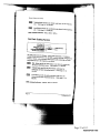
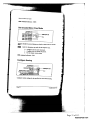
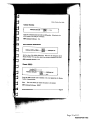
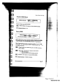
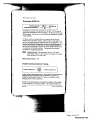
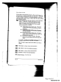
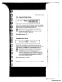
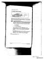
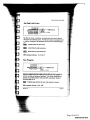
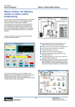
Get Fast Status to the appropriate parsing Vls. Place a Get Fast Status V1 in each while loop of an application that needs status information. Alternatively, use global variables to "broadcast" the fast status information to other loops_ Avoid using multiple instances of this VI within a single while loop as this will incur unnecessary overhead. 
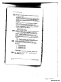
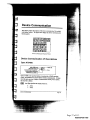
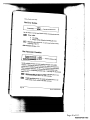
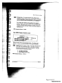
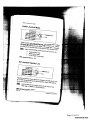
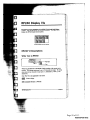
indexer. A: 9500 baud, it typically takes between 20 and 35 milliseconds to fetch a fast status block (cluster) from a 6200 indexer. By fetching only the status clusters that are needed, application performance is enhanced.
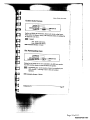
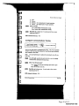
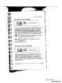
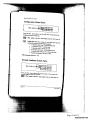
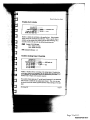
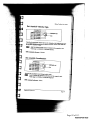
 Bit 1: Enable/disable fetching of Motor status. This cluster contains all motor and encoder positions and velocity information. Bit 2: Enable/disable fetching of Misc. status. This cluster contains the controller's axis status, system status and Bit 3: Bit 4: user status information. Enable/disable fetching of Timer status. This cluster contains values for the programmable timer and the two millisecond time frame mark. Enable/disable fetching of [/0 status. This cluster retrieves the current physical values for the inputs and outputs. 
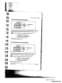
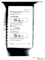
For example, to configure Get Fast Status to fetch only motor and [/0 status, set Fetch control to 1001 binary or 9 decimal.
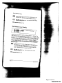
 Note: This input is ignored when Get Fast Status is used with an AT6400. i 
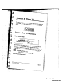
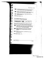
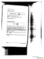
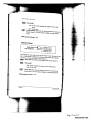
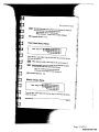
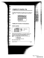
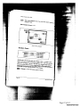
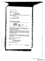
Motor status is a cluster of motor related parameters. Misc. status is a cluster of miscellaneous parameters. - Timer status is a cluster of timer related parameters. g A. S, ‘X 3. .. 1/0 status is a cluster of 110 related parameters. 6000 command reference: TAS, TSS, TUS ‘,. 1’ase42 Fart Status VI: i I. 5x Page 48 of 113 Page l('\)’GBINSP00017991 48 f 113 A5 .~-,:u;or—»Z<m.7is;-_ ,3 Q.J. Motion Toolbox User Guide Set Motor Pos Local Scaling Attic 1 [25000] mm Axis 2 Q5000} g --*- Data flow out (always true] a‘ Axis 3 [25000] H‘ Axis 4 (250113 W Sets the local scaling factors used by the Motor Position Parse VI. Use this VI "1 toyourscale distanoesto units convenient for your application. For example, if step motor is set to a resolution of 25,000 steps per revolution and the motor is attached to a linear table with a live turn—per—ineh leadscrew, the motor will travel 125,000 steps per inch (25,000 stepslrev * 5 rev/in). To -- i display inches, set the local scaling to 125,000 for the appropriate axis and the . i : informationAxisfrom1-4 thespecify MotorPosition Parse VIscaling will befactors formatted to inches. the motor position for the respective E axis. Each axis can have a unique scale factor. a~' Data flow out is always true. It can be used to force correct sequencing of this VI. ' { in ' 6000 command reference: NIA { til‘ % Set Encoder Pos Local Scaling An’ 1 [40011] ~ Axis 3 (mm) '5' 2 {mm} -- Data flow out (always true] Axis I (40801 Sets the local scaling factors used by the Encoder Position Parse VI. The scale factors are in posvquadramre counts. Use this V1 to scale encoder distances to units convenient for your application. For example, if your encoder is mounted on a linear table with a resolution of 10,000 counts per inch, the scale factor for that axis should be set to 10,000 to scale the encoder information to inches. E. 5 ‘ Fast Status W: Page 43 Page 49 Page 49 of of 113 113 RGBINSP00017992 Axis 1 (25000) Attic 2 (250001 Ass: 3 (251100) Axis 4 (250001 6000 command reference: N/A Page 44 Fastszams VI: 1 " Page 50 113 Page 50 of lggéI1N:;P00017993 I .1 § _ ; Motion Toolbox User Guide 3: Motor Position Parse 5 _ -_ ,_ '«ro\:~s.v-u»w’Aa+ Motot position axis 1 Mote: poskion axis 2 Mote: posiion axis 3 Mata posiion axistl Parses the Motorslams output of the GetFast Status VI into motor positions ! for each axis. If Scale locally is enabled, the motor positions are divided by the respective scale factor set by the Set Motor Pas. Local Scaling VI. 3 Motor status is the Motor status output of the Get Fast Status VI. WI! ~—« ~. _ fig ScaleTrue: locally? Divide motor positions by respective local scaling factor. ,I ‘Q ~ 35: False: Do not scale. Motor position axis 1-4 are the motor positions for each axis in motor steps, or, if local scaling is enabled, in scaled motor steps. § *5‘ I 6000 command reference: N/A Encoder’ Position Parse "do, flaw, 5 Scale locally? [F1 --~ 5 {El ; _‘ i. n ‘ s Encode: "°‘?”°".. positionaxis 1 Encoderposition axis 4 . .. Parses the Motor mm: output of the Get Fast Slams Vi mto encoder positions for each axis. IfScale locally is enabled, the encoder positions are divided by the respective scale factor set by the Set Encoder Pox. Local Scaling VI. 3, Motor status is the Motorstatus output of the GetFast Status VI. 5: V Q Fast Status V1: Page 45 Page 51 of 113 Page l('\)’GBlNSP00017994 51 f 113 Motion Toolbox User Guide Scale localiy? True: factor. Divide encoder positions by respective local Scaling False: Do not scale. Motot status ‘‘‘‘‘- v Scale locally? {Fl «-- - - - ~- \¥°:°°!-:3‘ §";° 5 V:,;’§q’ffig 3 Velocity info axis 4 scale factor set by the Se: Velocity Local Scaling VI. -3 Motor status is the Motor status output of the Get Fast Status VI. [E Scale locally? True: Divide velocities by respective local scaling factor. False: Do not scale. 6000 command reference: N/A Fast Status V15‘ Page 52 113 Page 52 of ggé}N%Pooo17995 Malian Toolbox User Guide Pos. Captured Status Parse "3311 Sta?!-If ' ---—- Position captured with TRG—A? Position captured with TFIG-B? 5-~ Position cqahned with TRG-C? Position captured with THG-D? Parses the Misc. status output of the Get Fast Status VI and returns booieans to indicate if a trigger input has captured its respective position. To retrieve the captured position, use the Transfer Captured Positions VI. Misc. status is the Misc. status output of the Get Fast Status VI. Position captured with TRG-A-D? True if a position has been captured for the respective trigger input. 6000 command reference: TSS Command Error Parse ~--~-'* Command Error? "‘._,1tw»:L-~in«uraVce<¢' Parses the Misc. status output of the Get Fast Status VI and returns the command error status of the 6000 controller. This command error bit remains set until cleared by a TCMDER query (see Milrcellaneous Transfer VI). Misc. status is the Misc. status output of the Get Fast Status VI. Command Error? True if the controller has received an unrecognized command since the last TMCDER query, power on, or reset. The Miscellaneous Transfer VI (issues a TMCDER query) will return the command string unrecognized by the controller as well as reset the command error flag. 6000 command reference: TCMDER Fast Status V1: Page 47 Page 53 Page 53 of of 113 113 RGBINSP00017996 Motion Toolbar User Guide Configuration Status Parse ’ Configstatusaxifl ”‘- Configstatusaxis2 " Config status axis3 Config status axis 4 Parses the Misc. status output of the Get configuration status of each axis. Fast Smms VI and returns the - Misc. status is the Misc. status output of the Get Fast Status VI. Config status axis 1-4 is a cluster of six booleans that report the axis specific status of the following parameters: 0 In absolute mode (true) / In incremental mode 0 - In continuous (true) / in preset mode In jog mode (true) I Not in jog mode G In joystick mode (true) / Not in joystick mode o In encoder step mode (true) / In motor step mode 0 Position Maintenance ON (true) I OFF . ~~~~~~~ -W Encoder status axisl "‘ Encoder status axis 2 ~ Encode: status axis 3 Encoder status exist! Parses the Misc. status output of the Ge: Fast Status VI and returns the .3»«An,ome;-_‘ encoder feedback status for each axis. - Misc. status is the Misc. status output of the Get Fast Status VI. Y” a Page 48 I v"-”'r“7~1’*5:‘f Fa.xtSIa1us Wx 5' m".-«'’:z*,“;‘”~s7 r7y.wf,v?;g Page 54 113 Page 54 of gf(;éI1N:;P00017997 Ha:dIimi2s£aiusaxis1 Hardflmitstalus axis2 ~ HardI'm'tstatusaxis3 Haa'dfimits£atusaxis4 Parses the Mzkc. status output of the limit status for each axis. I A E! ¢ 1 III! ~ Motion status axis 1 Motion status axis 2 Motion status axis 3 Motion status ads 4 \ < Fast Status V1: Page 49 ‘ Page 55 Page 55 of of 113 113 RGBINSP00017998 Motion Toolbox User Guide l Moving? True ifaxis is moving. Direction =-' CCW? True if axis direction is CCW. * ‘ Accelerating? True if axis is accelerating. A: velocity? True if axis is at velocity. Home suctesgid? True if axis home was successful. 6000 command reference: TAS Soft Limit Status Parse ~ ' Soft limit status axis 1 Soft Emil status axis 2 ~ Soft limit status axis 3 ' Soft firm’! status axis 4 0 CW. True if soft, clockwise limit was encountered. CCW. True if soft, counterclockwise limit was encountered. f ° 6000 command reference: TAS Page 50 Fast Status W5 ._ . Page 56 113 Page 56 of gf(9éI1N:;P00017999 Marian Toolbox User Guide ,-‘_.mt;nzv System Status Parse _~ System status gtoup1 ‘- System status goup 2 System status group3 Parses the Misc. status output of the Get Fast Status VI and returns the system status. } Misc. status is the Misc. status output of the Get Fast Status VI. System status group 1 is a cluster of cightbooleans that report the system status of the following parameters (true = yes): 0 System ready? Bufierfill? (AT6400 only) Executing a program? Immediate command? Set true if last command was immediate) In ASCII mode? In echo made? Defining a program ? In trace mode? System status group 2 is a cluster of eight boolcans that report the system status of the following parameters (true = yes): C0 Fast Status V]: In step mode? In transiation made (6400) ? Command error occurred? This boolean (status bit) is cleared when the TCMDER command (via the Miscellaneous Transfer V!) is issued. Break paint active? Pause active? Wait active? Monitoring on condition? Waiting for data? Page 51 .‘_,V4H“ Page 57 Page 57 of of 113 113 RGBINsPo0018ooo C O I O O O O C Loading thumbwlzeel data? Externalprogram select mode? Dwell in progress (I command)? Waitingfor RP240 dzda? (62XX) ? RP240 connected? (62}C5() .9 Abmvolazile memory errvr (62XX) ? Servo data traI:.m2i.s‘3z'on? (6250) Reserved 6000 command reference: TSS Drive Status Parse Shutdown? True if drive is shut down. - Fault? True if drive fault has occurred. 6000 command reference: TAS Page 52 Fast Status VI: Page 58 113 Page 58 of lggéI1N:;P00018O01 mfiei. ,; ‘ .:i Motion Toolbox User Guide User Status Parse J!.!-‘_ User status bits1-B User status bits 346 Parses the Misc. status output of the Get Fast Status VI and returns user status information. .2!’ 3 Misc. status is the Misc. status output of the Get Fast Status’ VI. User status bits 1-8 is a cluster of eight booleans that report‘ the status of the firs: byte of the user status. I». User status hits 9-16 is a chxstcr of eight booleans that report the status of the second byte of the user status. 6000 command reference: TUS, INDUSE, INDUST Timer étatus Parse . Tune‘ mm: 2 ms counter Programmable timer value Parses the Timer status output of the Get Fast Status VI and returns the 2 ms time framecmmter and the programmable timer values. The prograrnmable timer is started and stopped with the Start 6000 Timer and Stop 6000 Tmer Vls. Timer status is the Hmer status output of the Get Fast Status VI. 2 ms counter contains the value of the counter. Range is 0 to 65,535 counts. The counter rolls over after 65,535. I352; Programmable timer value contains the value of the programmable counter. Range is zero to 999,999,999 milliseconds. 6000 command reference: "(TIM Fast Status VI: Page 53 Page 59 Page 59 of of 113 113 RGBINsPo0018oo2 Fart Status VI: Page 60 Page 60 of of 113 113 RGBINsPo0018oo3 Motion Toolbox User Guide Home limits is a cluster of four booleans that report the actual physical status of the home limits for all axes. The boolean order is from axis one to four. 0 Axis 21. True if home limit is currently active. 6000 command reference: TLIM Joystick Status Parse ;---—-— Joystick auxtlaty input __jfi:-- Joystick trigger input mm ‘- Joystick axis select input ‘E ~- Joystick velocity select input '“-~ Joystick release input Parses the [/0 status output of the Get Fast Status VI and returns the status of the actual physical state of various joystick inputs. ti IIO status is the [/0 status output of the Get Fast Status VI. . Joystick auxiliary input is true if pin 19 of the joystick connector is cumently active. Joystick trigger input is true if pin 18 of the joystick connector is currently active. Joystick axis select input is true pin 15 of the joystick connector is currently active. Joystick velocity select input is true if pin 16 of the joystick connector is currently active. Joystick release input is true if pin 17 of the joystick connector is cumently active. 6000 commanti reference: TINO I Fast Status V1: l Page 55 1 Page 61 Page 61 of of 113 113 RGBINsPoo018oo4 Parscs the 1/0 status cutput of the Get F ; 3“ P1’Ogrammable digital oulputs. ‘ as: Status VI and refilms the status of U0 status is the I/0 status output of the Get Fast Status VI Fas! Status VI: Page 62 of 113 Page l('x)’GBlNSP00018005 62 f 113 Motion Toolbox User Guide Pulse cutoff is true ifpthe pulse cutoff input is grounded. Note: The pulse cutoff input must be grounded (active) before any motion can take place. 6090 command reference: TINO Digital Input Parse T rigge: inputs A-D Parses the 1/0 status output of the Get Fast Status VI and returns the status of all digital and trigger inputs. - »._, *\.»K-,‘_r VI ~-»:.« 1.! I/O status is the [/0 status output of the Get Fast Status VI. Inputs 1-8 is a cluster of eight booleans that indicate the status of the first byte of programmable inputs. A given boolean is true if the input is currently active. Inputs 946 is a cluster of eight booleans mat indicate the status of the second byte of programmable inputs. A given boolean is true if the input is currently active. Inputs 17-24 is a cluster of eight booleans that indicate the status of the third byte of programmable inputs. A given boolean is true if the input is currently active. . g f Trigger Inputs A-D is a cluster of four hoolcans that report the status of the trigger inputs. A given boolean is true if the trigger input is currently active. 6000 command reference: TIN gt Fast Status VI: Page 57 ___._....r,.‘,Z_,._..&‘ Page 63 Page 63 of of 113 113 RGBINSP00018006 A: I/0 & Limit Vls J. -!'-‘ .,«~4V1w This chapter contains descriptions of the I/O and limit Vls included with Motion Toolbox. The figure below displays the 1/0 & Limils function paleue. L/O & Limits Function Palette lg Q} I/O 8: Limit Vl Descriptions Set 6000 Input Active Level EnecutaVl?{T) Addrlpmt [default] Input byte 1 [fro change) input byte 2 [no change) Input bvte 3 [no channel Addrfpofl out Defines the active state of all programmable inputs. The active level can be defined for each input individually. The 6000 series default state is active low. Home and Iimix active levels are set using the Cazgfigure Home and Set Hard Limit Active Level VI: respectively. I/0 & Limit VI: Page 64 Page 64 of of 113 113 RGBINsPo0018oo7 Motion Toolbox User Guide 0: Set input to active low. 1: Set input to active high. 2: Do not change current setting. 6000 command reference: INLVL Enable 6000 Inputs Addtlpmt out Input byte 1-3 are clusters of eight. 32-bit integers that specify the enable/disable state of the corresponding input. Each cluster is ordered from the least significant input to the most significant. 0: Disable input and leave off. 1: Disable input and leave on. 2: Do not change enable setting. 3: Enable the inp . 6000 command reference: INEN E .~i;Y_/Vr-‘,~. ~'—&$,¢*JI4OWV°o’»3(.-v<f‘ Page 65 113 Page 65 of lgf(;éI1N:;P00018O08 Motion Toolbox User Guide or Set 6000 input Function immediate? [T] »---——--3 E>eecufeVl? [T] -*~~“~--= Addtlport [default] Axisfpsog [1] Input [1] Function [0 = A) Addrlpotl out Im """""- Error v1, use the Enable 6000 Input Funciiom VI. 1 Axislprog specifies the axis number if required by the function or in the case of fimction 15, it specifics the program number to execute. IE8: Input specifies the input number to define. 1122:: Function specifies the function to assign to the input and axis. 0: 1: 2: No special function BCD program select Kilt 3: Stop 4: PauseIContinue 5: User fault 6: Reserved 7: Trigger interrupt (Position Capture and Registration) 8: Interrupt to PC—AT 9: Jog CW 10: Jog CCW 11: log speed select 12: Reserved 13: Reserved 14: Reserved 15: Program select 6000 command reference: [NFNC [/0 & Limit Vls Page 61‘ Page 66 113 Page 66 of i('x)’glE13I1N%P00018O09 Motion Toa!box User Guide Enable 6000 Input Functions Immediate? {T Execute V]? {T} Addrlport [aetaum Enableldisahle [enable] *5 5 .£a’:.'-I’ E Enableidisable. True: Enable input functio us and drive fault input. False: Disable input functions and drive fault input. 6000 command reference: INFEN, INFNC, DRFLVL Set 6000 Input De-bounce Time Addrlpott (default) Input [1] Debouce tine [50 ms] -.a:'»- Addrfpolt out Error unique dcbounced tnne to each of the tri milliseconds in even increments. The gger inputs. The range is 2 to 250 6000 general purpose inputs and 50 ms for the tri series defaults are 4 ms for the gger inputs. Input. Page 67 113 Page 67 of gf(;éI1N:;P00018O10 Motion Toolbox User Guide Debounce time. For a general purpose input, Debounce time specifies the amount of time the input must be held in a certain state before the 6000 Series controller recognizes it. This directly affects the rate at which the inputs can change state and be recognized. For a trigger input, Debounce time specifies the time required between a trigger's initial active transition and its secondary active transition. This allows rapid recognition of a trigger, but prevents of the input causing a false position capture or subsequent bouncing registration move. 6000 command reference: INDEB Set 6000 Output Active Level immediate? {T} ~~~~—~-°-M5 Executelfl? [T] *~-‘~-* Addtlport [default] Output byte 1 (no change] ’ BMW,” 2‘ , I MW-.9_r:23 Addripert out 0utaI1Ibyl:3[:£cftartg:] — Defines the active state of all programmable outputs. The default state is active low. The active level can be defined for each output individually. - Output byte 1-3 are clusters of eight, 32-bit integers that specify the active state of the corresponding output. Each cluster is ordered from the least significant input to the most significant. The eight .na-« clustered integers are interpreted as follows. 0: Set output to active low. 1: Set output to active high. 2: Do not change current setting. 6000 command reference: OUTLVL Page 68 of 113 Page6 l('\)’GBINSP00018011 8 f 113 Motion Tooibax User Guizfe Enable 6000 Outputs Inunediate? ff] ~*-~---; Execute Vi? (T) —-~~--;. Addrlport {default} ‘ Byte 1 {no change] 1 Byte 2 [no change] ~ liyte 3 [no chance) ‘ 3 H Addrlporl out EH0! Enables or disables the specified outputs. It is used for troubleshooting and initial start-up testing. It is generally not used within a program. The 6000 series default state for each output is enabled. V ; Byte 1-3 are clusters of eight, 32~bit integers controlling the enable/disable state of the respective output. Each cluster is ordered from the least significant output to the most significant The eight 3 clustered integers are interpreted as follows. 0: 1: 2: 3: Disable output and set to off. Disable output and set to on. Do not change current setting. Enable output. 6000 command reference: OUTEN Set 6000 Output Function Immediate? [T] ----------------Execute VI? {T} W Addtlpott Ideiaultl Am: {I} output [1] Function [0 = A) imffotn 8m Addrlporl out Error Defines the function corresponding to the specified output and axis number (if required). Bach output may be assigned a unique function. The default condition is function 0 for all of the outputs. To enable the functions by this i VI, use the Enable 6000 Output Functions VI. i Output specifies the output number to define. Page 64 1/0 & Limit VI: Page 69 Page 69 of of 113 113 RGBINsPo0018o12 a --'9 I t Ii! E i mi Motion Toolbox User Guide E Function specifies the function to assign to the output and axis. ‘T I. 0: Programmable output I: Moving/Not Moving Axis, axis specifier optional 2: Program in progress 3: At limits, hard or soft, axis specifier optional 4: only Stall indicator, axis specifier optional -~‘ stepper products 5: Fault output (indicates drive or user fault) 6: Position error exceeds maximum limit set with SMPER command — servo products only. 72 Output on position - servo products only 6000 command reference: OUTFNC if t, Enable 6000 Output Functions lmmedate? {T} ------~-; Execute‘~fl?(T]*““‘““"§ Addrlpolt (defadl) Enahleldisahie {enable} ~—-- E . Addripurt out lg Em Enable or disables the output ftmctions defined by the Set 6000 Output Function VI. If output functions are disabled, the outputs can be used as L 3 1 programmable outputs only. Enable/disable. True: Enable output functions. False: Disable output functions. 6000 command reference: OUTFEN I/0 & Limit Vls *.z'_,:a Page 65 Page 70 113 Page 70 of l('\)’GBlNSP00018013 f 113 Motion Toolbox User Guide Set 6000 Output States Immediate? [T] -«----3 Execute VI? {T} Addslpotl [defaultl : Output byte 1 (no change) ’ Output byte 2 [no change] Output byte 3 {no chance} affect the state of an output, that on using the Set 6000 Ouqzut Function VI. ,.~w« .W‘rM_A-7 Output byte 1-3 are clusters of eight, 32-bit integers that specify the 0: 1: Set output off. Set output on. 2: Do not change setting. Note: The integers of the clusters Output byte 1-3 do not necessarily correspond one-tome with the physical 6000 outputs; the integers correspond to outputs configured as programmable outputs. I/0 & Lfmit VI! “,.-wm:«z~‘*+<n A52’3:;‘ Page 71 113 Page 71 of l('x)’géI1N%P00018O14 ‘Im*"s{p¥-,3«v:uant Motion Toolbox User Guide Configure Hard Limits lmmeolate? {T} --~-~~_; Execute VI? {T} Addnlpott [delaufl] Axis [I] cut active level 7 CCW active level Hatd Emit decal [no change] Defines the active state of the limit inputs and deceleration used when a hard limit is encountered. For safety reasons, the 6000 series default state is active low. CWICCW active level. True: Limit is active high. False: Limit is active low. — Hard Limit Decel defines the deceleration rate in the event an end» of~travel limit is encountered. The range is 0.00025 — 24,999,999 units/sec‘ The 6000 series default value is 100 units/sec‘ A~-mesa. W'~.u5=,4hz‘* 6000 command reference: LHLVL, LHAD Enable Hard Limits E:-eecuie Vl? [T] » Addtlport [default] Axis (ll ; Enable CW Emit? [T] ---‘ Enable CCW Emil? [T] W---5 Addrlpost out Enor Enables or disables the use of the hard wired limits. With the limits disabled, motion will not be restricted. When a specific limit is enabled, and the limits wiring for the enabled limit is physically active according to settings issued by the Set Hard Limit Active Level Vl, motion will be restricted. The 6000 series default condition is enabled. I/0 & Lina’! Vls .- Page 67 Page 72 Page 72 of of 113 113 RGBlNSP00018015 Motion Toolbox User Guide @ Enable cw/ccw limit True: Enable limit. False: Disable limit. 6000 cummand reference: LH Configure Soft Limits |mn1ed?a!e?{T)”“~~~~~ ExecuteV1?[T}~«----- Add:/pod [default] mm CW limit range [no change} ‘h @ Addnlpolt out ,«D.’u¢ range [no change) Soft Emit decal [no change} maximum absolute position the axis can travel unrestricted. The range is -999,999,999 to «$999,999,999 units. Soft Limit Decel defines the deceleraticn tale in the event an end- of-travel limit is encountere d. The range is 0.00025 to 24,999,999 units/sec’. The 6000 series default value is 100 units/secz. 6000 command reference: LSCW, LSCCW, LSAD Page 68 1/0 & limit VI: ,.wW»\-«~—* Page 73 113 Page 73 of gf(;éI1N:;P00018O16 Motion Toolbox UserGuide Enable Soft Limits V. lmmedate‘? m —~~-~--7 Execule VI? [T] ~~'~-Addrlpott [default] . —; 1 Addrlporl out Error Attic [1] Enable cw Emit? m Enable can limit? m ———i Enables or disables the soft limits on the specified axis. When disabled, motion will not be restricted by the soft limits. When a specific limit is “I enabled, and the absolute limit defined in the Set Scfi Limit Range Vl is exceeded, motion will stop at the pro-defined deceleration rate. Enable CW/CCW limit. ' True: Enable soft limit. 1‘ False: Disable soft limit. 6000 command reference: LS Enable Analog Input Override Execute VI? fl] Add:/port {default} 1 Addrlport out ____ Ch. 1 [F-—di:ahle] -fin ’ Ch. 2 [F=di:d:le) M" : Ch. 3 (F—.-disable] ~-~~~--4 Ch 4 fl:=d;3ab]e] ...............-5 Enables or disables software overriding of the analog inputs. If enabled, the analog input values are as specified by the Set Analog Input Override Voltage VI. If disabled, the analog input value are as determined by the actual hardware input voltages on the joystick connector. The joystick release input (pin #17 on the Joystick connector) is not monitored when override is enabled for any analog input channel. Thus, you can enter the joystick mode and simulate joystick operations without having to wire that input. ’ ”‘ I/0 & Limit VI: Page 69 Page 74 Page 74 of of 113 113 RGBINsPo0018o17 Motion Taolfiox User Guide CI: I-4. (Product dependent) True: Enable analog input override for respective channel. False: Disable analog input override for respective channel. 6000 command reference: ANVOBN Set Analog Input Override Voltage '-,.m_J«~1:w%*v; r.m/z-rs. Immediate? {Tl ~'~-----g Execute VI ? [T] --~--"M Addtipoct [default] Channel [1] Override «mirage 11.2441 _ ._ *- kdtifpott out Error —;-.u~vw4m‘ Channel specifies the analog input channel to set. Valid channels are one to four and are product dependent. flb4,.‘%_?I:V< Page 70 1/0 & Limit Vls Page 75 113 Page 75 of l('\)’GBlNSP00018018 f 113 Marion Toolbox User Guide Define 6000 User Status Immediate? [T] Executevl? [T] Addrlpnrt [default] Use: statu: bit [1] Reference bit [1] Status to reference [8 = A] Addrlport out gig, EHO! Defines the bits of the user status word. The user status word is a configurable combination of status bits referenced from other 6000 status words. ‘This facility allows you to create your own application-specific status word. This status word is retrieved with the User Status Parse VI. 3 User status bit specifies the user status bit to define. Valid range is 1 to 16. 3 Reference bit. Specifies the system status, axis status, input #, or ' interrupt status bit to reference. Valid range is 1 to 32. |;_:«z;_; Status to reference. Specifies the status information to reference. A - axis status for axis l B - axis status for axis 2 .‘?“>’°"!-*':9 C — axis status for axis 3 (AT6400 only) D - axis status for axis 4 (AT6400 only) 13 - reserved F - reserved G - reserved H - reserved I - system status 1 - input status 10: K - interrupt status (AT6400 only) 6000 command reference: INDUST I/0 & Limit V1: Page 71 Page 76 Page 76 of of 113 113 RGBINSP00018019 Motion Tooibox Uxer Guide Enable 6000 User Status immediate? {T3 ---—--3 Execute VI? [T} v-——--; Addrlport [default] Enablehfisable [enatde] Enables or disables the 6000 User Status VI. - update of the user status word defined by the Define Enablefdisable. ., True: Enable update of user status. ; False: Disable update of user status. 6000 command reference: INDUSE, INDUST Page 72 2 34 3 1/0 & Limit VI: Page 77 Page 77 of of 113 113 RGBINSP00018020 Jogging & Joystick Vls This chapter contains descriptions of the jogging and joystick Vls included with Motion Toolbox. The figure below displays the Jogging & Joystick function palette. ample :09 v pg 1: ‘ % cubic veilow velllih at am. ’6U4‘ «ed deed -‘cue Jogging & Joystick Function Palette Jogging and Joystick VI Descriptions 1; Enable Jog Mode immediate? m -«--«»—-~3 Executa Vi? [T] ------~~-3 Addripott [default] Axis 1 {no change] Axis 2 [no change) this 3 {no change) Axis 4 [no chance] Addtlp-on out EHO! Enables jog mode on the specified axes. Once jog mode is enabled, the jog inputs can be used to produce motion on the specified axis. Inputs are configured as jog inputs using the Set 6000 Input Function VI. — Ki ' Axis I-4 enablesldisabies the jog mode for the respective axis. 0: 1: 2: 6000 command Disable jog mode. Enable jog mode. Do not change current setting. reference: 106 Jogging & Joystick Vls Page 73 Page 78 Page 78 of of 113 113 RGBlNSP00018021 Motion Toolbox User Guide Set Jog Velocity Low Immediate? (T1 -------—. Add"Execu‘te vrz m ~-—~~—; part [default] Axis 1 {no change] Axis 2 {na change] 3” Addri Ema: 3°" W 223': 3 (no change] lmmecfiate? m ~--—-~~——= i? _* ’ Add I Execute VI?{T} -~—-~-~—~; Axkrfiatzxg ldefaultil Asia 2 [no change] Axi: 3 [no change) :09“; ‘R’ Addripott out Error Axis I! [no change} ,.«47‘~M»<.'+uA:1rmI“;-v Jogging & Joystick VI: .«_~,r-¢w:fv'* Page 79 113 Page 79 of gf(;éI1N:;P00018O22 Mozion Toaibox User Guide Set .109 Acceleration Immediate? [F] ------; Execute W? [T] --—~—~; Adciiport ldelaulti iog Axis 1 {no [no change} Anti: 2 change) ad Addllpolt out Em Axis 3 [no change] Ari: 4 [no change] Specifies the acceleration used during jog mode. X, Am 1-4 defines the jog acceleration for the respective axis. Valid E range is 000025 to 24,999,999 steps/sec’. 3" § 6000 command reference: JOGA , 1 T ; '5 i ‘ § ‘ 5 W 3‘ § (I ,0 E», ‘ ‘ ‘7 1 1 V fM i Set Jog Deceleration %‘ Immediate? {T} ""“*"“"“'g Execute VI? (Tl ‘ Addtlporl Idelaultl Mi: 1 (no change] Axis 2 [no change) ‘V 4; ;h ,~ $3 ; ' ; 3 Eno gauge: I: no ange . 3 3 * 3 3' _e Specifies the deceleration used during jog mode. ‘ 7 § Axis L4 defines the jog deceleration for the respective axis. Valid (‘ “ . f Il .1 range is 0.00025 to 24,999,999 steps/sec}. 6000 command reference: IOGAD '.-«~,¢:_L .4 31 L 3 i » Jogging & Joystick V1: Page 75 7 9. _t, ‘ M5 $ Page 80 Page 80 of of 113 113 RGBINSP00018023 Enable Joystick Mode emmévsg: [port meraim) ’" change] change] 0: Disable joystick mode. 1: 1e joystick mode. not change current setting. W “. , Page 81 113 Page 81 of f—3gé.u1N3.¢,Pooo18o24 gfe ExeculeW?{T} Addrlporl ‘ 1 [no [default] change) A: :i 3‘ Axis 2 [no change} Axis 3 [no change} Axistlnochangel . ty that can be obtazned at full defleenon (0 VDC or 2.5 VDC) during joystick mode wlule thejoystick velocxty select mput on Axis 1-4 defines the highjoystick velocity for the respective am the joystick connector is high. Valid range is 000020 :0 1,600,000 steps/sec 71 If ;» ‘ £1 6 f‘ * ‘ ~ 9I . 6000 command reference: IOYVH 9K = ‘. ; H Set Joystick Acceleration Axis 2 [no change) _ E5tis V Addriport out 2 ‘ [ii ? E. ’ A105: 3 {no change] Axis 4 {no change] Specifies the acceleration used during joystick mode. - Axis I-4 defines thejoystick acceleration for the respective axis. Valid range is 0.07500 to 24,999,999 steps/sec2. 6000 command reference: JOYA Jogging & Joystick VI: Page 77 Page 82 113 Page 82 of l('x)’ff9lE13I1N%P00018O25 Motion Toolbox User Guide Set Joystick Deceleration ~“"A‘{h*1-\.u»fl:’ .;-W2mw,_ 9: ’ Ali: 2 [no change] Axis 3 [no change] Axis 4 [no change] Specifies the deceleration used during joystick mode. ‘ _ Axis L4 defines the joystick deceleration for the respective axis. 9’ Valid range is 007500 to 24,999,999 stepsfsecl. 6000 command reference: JOYAD Setup Joystick Electronics Immediate? [T] ~-W---~‘~*~—; Execute VI? (1') -~-~--*3 Addtlpoct (default) ‘ Analog channel (1) Center {no change) Add!/port out Eaot Centet deadband (no change) End deadhand {no change} a given analog channel for use in 2.5 volt input. joystick inputs are eight—bit ADCs with a 0 to Analog channel specifies the analog input channel to define. Valid range is 0 to 4, product dependent. 1333; Center defines the voltage level for the analog input that commands no motion. Valid range is 0.15 to 2.40 volts. Page 78 Jogging & Joystick Vls » Page 83 113 Page 83 of l('\)’GBINSP00018026 f 113 Motion Toolbox User Guide - End deadband defines a voltage range at the upper and lower ends of the joystick input voltage beyond which the commanded velocity does not change. Valid range is 0.00 to 1.24 volts. 6000 command reference: JOYCTR, JOYCDB, JOYEDB Set Joystick Analog Inputs lmmetiate? [Tl Execute VI ? [Tl Addrlpott (default) _ An: [1] channel but {0=no selection) Channel high [0=no seledion} Addllpotl out Specifies the analog channels that will control motion during joystick mode. The axes select input on the joystick connector determines which analog channel (low or high) will control the motion. Channel low defines the analog channel that will control the specified axis during joystick mode while the joystick axes select input is low. - Channel high defines the analog channel that will control the specified axis during joystick mode while the joystick axes select input is high. 6000 command reference: JOYAXH, IOYAXL Jasging & Joystick VI: Page 84 of 113 Page l('\)’GBlNSP00018027 84 f 113 Page 85 of 113 This chapter contains descriptions of the miscellaneous Vls included with Motion Toolbox. The figure below displays the Miscellaneous function palette. ' Miscellaneous Function Palette Miscellaneous Vl Descriptions Numeric Event Force all true? """“"“‘; r-~-- Some value changed ' W‘ Voile A changed ":'=~ Value 8 changed 3 ‘W Value (I changed 5-W" Vane D changed Monitors up to four numeric inputs for a change in value. A change in value flags an event that sets the corresponding output to true. The Force all true? input forces all outputs to be true. The Same value changed output indicates that one or more of the four inputs changed in value. The example below displays how the Numeric Event V1 is used to only send velocities to the 6000 controller when the velocity setting changes. 3 Value A - D are the numeric values to monitor. Force all true? When true, forces all outputs to be true. The example below displays how this input is used to force the Set Velocity VI to execute the first time through the while loop. E1 Value A - I) changed is true if the corresponding input has changed in value. Miscellaneous Vlr Page 81 Page 86 Page 86 of of 113 113 RGBINsPo0018o29 Motion Toolbox User Guide Numeric Event Example Boolean Event A.»-,:’1«"g;7f>lr_j'v*x‘ Page 82 Miscellaneous V1: Page 87 113 Page 87 of Of113 RGBINSP00018030 Motion Toolbox User Guide Force all true? When two, forces all outputs to be true. The Boolean Event example below displays how this input is used to force the Set Direction VI to execute the first time through the while loop. A - D state changed is true if the corresponding boolcan input has changed in state. Some value changed is true if any of the four boolean inputs has changed in state. 6000 command reference: N/A Boolean Event Example Boolean Transition ‘ —~~~— Lomohitjt Sm’ Force Transition [B=no] --~ *“-- High-to-low State Change Monitors a boolean input for a state transition. A transition flags an event that sets the appropriate output to true. State. The boolean variable to monitor. Miscellaneous V1: ._W-,w4 Page 33 321 Page 88 Page 88 of of 113 113 RGBINSP00018031 Marion Toolbox User Guide - Force fiansition. Forces the state of this VIs outputs. 0: Do not force. 1: 2: Force low-to-high transition. Force high-to-low transition. [:i_:] Low-to-high. Indicates monitored booiean transition. input made a 1ow—to-high High-to-low. Indicates monitored boolean input made a high-to—low transition State Change. Indicates monitored boolean input made either a low-to—high or high-to-low transition. 6000 command reference: N/A I/‘l(.iV«,q» Page 84 «u.to-x/,—<~a45w1»r'‘ Miscellaneous W: E‘w'"W:.-u~>*¢“‘ Page 89 of 113 Page l('\)’GBlNSP00018032 89 f 113 x 1 E! It1 5 Motion Vls ‘'"“w*aun—\.»m¢ This chapter contains descriptions of the motion Vls included with Motion Toolbox. The figure below displays the Motion function palette. HEW“ Eagm 5E fifififi BEE Motion Funclian Palette 2! M‘i._“ Motion VI Descriptions initiate Motion Addtlpotl (detaum _“__ Start axis 1? [F] -5 7.Start axis 2? [F] -—~= = 5 seat axis 3? [F] —~-~—-~5 ‘ gitatt axis 4? [F] ~~~~~~~--= 1 .~—v- .,' \V. A4=_ _ Addrlpoxt out Error Initiates motion on the specified axes. If motion does not occur after executing this command, verify the drive fault level, pulse cutoff and limits are configured properly. Start axk 1-4. A true initiates motion on the respective axis. 6000 command reference: G0 _.-“a— ‘g:2; Motion Vls Page 90 Page 90 of of 113 113 RGBINsPo0018o33 Motion Toolbox User Guide Stop Motion Immediate? {T} ''''''''-*= Enewts W? [T] ---‘--‘ Addtlpott (defauk) Stop axis 1? [F] Stop ad: 2? [F] ' Stop axis 3? [F] "' stop a‘i: ........... Addrlport out Enor 6000 command reference: 8, COMEXS Set Distance Immediate? m~««««---Execute‘??? m -«~—~~~ Addrfpoll [defaul] Axis I [no change] Axis 2 [no change} ‘ 3 ; Addzlpolt out fi‘..’f’§ 4 EL’: c..a. g°””‘”:§ 3% ‘M4:-=._1'~;«" Axis I — 4 defines the distance for the respective axis. 6000 command reference: D Page 86 Motion VI: J‘.:C§,V«>h_1i/;\s~- Page 91 113 Page 91 of lggéI1N:;P00018O34 Motion Tooibox User Guide lmmediate? 111 »~--~~—§ Execute VI? [T] Adtiiport [default] Axis [%ill all I» stop] Addtlport out Warning for Stepper Since commanded mo Systems: This command should be used with caution. tion is stopped instantaneously, without a controlled deceleration ramp, high inertial loads may cause a dn’ Axis. Specifies the axis to kill. 0: .~—u Kills motion on all axes but continues command execution. l~4: 5: Kills motion on specified axis. Kills motion on all axes and stops command execution. 6000 command reference: KILL, COMEXK Motion V]: Page 87 Page 92 113 Page 92 of l('x)’glE13I1N%P00018O35 Motion Toolbox User Guide Set Veiocity ‘.1-g:¢_“’‘ Immediate? {T} *Execute VI ? {T1 Addrlpott [default] Axis I [no [no change! change] Axis 2 ,.«+»~-e<“’ .-r,_‘p:¢T a _ 4’ ‘ - Axis 3 [no change] . Axis 4 (no change} Sets the velocity for the specified axes in units per second. The velocity remains set until changed with a subsequentfiez Velocity command. If scaling is enabled, the velocity values are intemally multiplied by the velocity scaling ‘. T :1 0 t Z‘ v factors (see Se! Motion Scaling Factors VI . Axis I-4 defines the velocity for the respective axis. 6000 command reference: V Set Acceleration Addtiporl (default) Axis 1 (no change) A33: 2 {no change] Addriport out “ EH0! Axis 3 [no change} Anti: 4 (no change} Sets the acceleration rate for the specified axes in units per second squared. The acceleration rate remains set until changed with a subsequent Se! Acceleration command. If the deceleration rate has not been defined, the 5 acceleration rate will be used to stop motion. Once the deceleration rate has ; ’ enabled, the acceleration values are internally multiplied by the acceleration ' f been defined, the acceleration rate no longer affects deceleration. If scaling is ’ -. , p v ‘ . - scaling factors (see Set Motion Scaling Factors VI). IL’! Axis I - 4 defines the acceleration for the respective axis. 6000command reference: A E§ ‘fl I ‘V W.5,‘f%lZag’ Page 93 of 113 Page l('\)’GBlNSP00018036 93 f 113 Motion Toolbox User Guide Set Deceleration EHeculeVl? IT} ————e-—~; Z Addrlpon (delaultl Addllpult out Axis 1 {no change) Axis 2 [no change] 5'80! Attic 3 [no change} Axis 4 [no channel x 9!‘ 5! Sets the deceleration rate for the specified axes in units per second squared. The deceleration rate remains set until changed with a subsequent Set Deceleration command. If the deceleration rate has not been defined, the acceleration rate will be used to stop motion. Once the deceleration rate has been defined, the acceleration rate no longer affects deceleration. If scaling is enabled, the deceleration values are internally multiplied by the acceleration scaling factors (see Set Motion Scaling Factors VI). ’ Axis 1-4 defines the deceleration for the respective axis. 6000 command reference: AD ¥-l3.-!‘ Set Direction Execute W? {T} -— ._~ ;_{\‘,1' veil Axis (1 1 M¢Ipon - , Mdrlnort [default] our Direction [cw-.-11 —-7 '*'=<*Emx ._,~‘ Sets the direction (clockwise or counter-clockwise) for the specified axis when in the incremental or continuous mode. The sign of a subsequent Set Distance VI will override this Vl. ‘ IE3 Direction. True: Set direction to clockwise. False: Set direction to counter-clockwise. .i<:>_2s;'4J1-,‘$&»"xu 6000 command reference: D ' Motion VI: Page 94 Page 94 of of 113 113 RGBINSP00018037 Motion Toolbox User Gmkfe Go Home Immediate? {T} -~——-—~-——Execuie Vi? (T Addtipott [default] Home axis 1? [2=no) Home axis 2? [2-mo) Home mi: 3? [2=no1 Home axis 4? [2==no] -.w,;W_1v~l»:' Addrfpott out Axis I-4 determines the direction of the homing search. 0: 1: 2: i‘;«~-*vT7"f“0'< Home clockwise. Home counter-clockwise. Do not home. 6000 command reference: HOM initiate Linear Int. Motion immediate? (T1 -W ““"""'§ Execute Vl?[T] -------------W. Addrfport [default] Start axis 1? [F] ~~’T_‘Z.' Start axis 2? [F] W‘ Start axis 3? [F] Statt axis 4? [F] -—-~--- ’ Initiates linear interpolated motion on the specificd axes. Linear interpolated moves cause all axes to start and stop at the same time regardless of the distances traveled by each axis. The end point of the linear interpolated move Page 90 Motion V15 _v).sm-M\,§ Page 95 113 Page 95 of l('x)’glE13I1N%P00018O38 Motion Toolbox User Guide is dictated by the values entered using the Set Distance VI. The vector velocity and acceleration are determined by the Set Path Velocity & 6000 command reference: GOL Set Position Immediate? (T) Execute VI? [U W Addrlnoxt tddaultl Axis I [no change] Axis 2 [no change] Axis 3 [no change] Axis 4 [na change) Adcklport out Defines the current, absolute—position counter for each axis. All values are in steps unless scaling is enabled (see Enable Motion Scaling VI), in which case values are multiplied by the distance scale factor (see Set Motion Scaling Factors VI). Axis I - 4 defines the absolute position for the respective axis. 6000 command reference: PSET '‘’“".-\»<;x,¢£f Motion V1: Page 91 Page 96 of 113 Page l('\)’GBlNSP00018039 96 f 113 Motion Toolbox User Guide Wait for Move Complete Execute vn Addripott [default] Poll-Time E ma Wait ~il ,; 5 1 V M.;,3»~el_v‘« Poll-time specifies in milliseconds how often the axes are checked for a non-moving status. Extra Wait specifies in milliseconds how long after motion has completed this VI waits before returning to its caller. 6000 command reference: N/A Run Path lrmtetfiate? [T] E2-:ecute\/I? [TJ Addtipott {default} Path program name . Addrlport out Executes a previously compiled (defined) path. if any of the axes included in the specified path are not ready, the path will not execute. An axis is not ready if it is in shutdown, moving, or in joystick or jog mode. When path .~T;=_, . execution begins, all included axes become busy until path execution is finished. Path program name specifies the name of the path to execute. 6000 command reference: PRUN v«>4:";-,‘W._T~1’“q)y<el/hIa3' x;., /‘_§:,.-¢ Page 97 Page 97 of of 113 113 RGBINsPo0018o4o Motion Toolbox User Guide Execute VI ? (TI "Addrioon [default] Velocity (no change] Acce! [no change] Decel {no chance] Specifies the velocity, acceleration, and deceleration values used in linearly interpolated and contouring moves. For both move types, the parameters refer to velocity, acceleration, and deceleration of the load as it proceeds along the path. Velocity defines the path velocity. Aocel defines the path acceleration. Decel defines the path deceleration. 6000 command reference: PA, PAD, PV Run Program Execute vi? [T1 ~- Program name AddI!®£l ? Addrlport [default] out g Error Executes a program previously defined with the DEF command. A program name must consist of 6 or fewer alpha-numeric characters. Use Motion Architect to define and debug your programs. You can then download your programs to the 6000 controller within LabVIEW using Motion 'l‘oolbox’s Download 6000 File VI. Program name specifies the name of the program to execute. 6000 command reference: RUN, DEF Motion V1.3‘ Page 93 Page 98 Page 98 of of 113 113 RGBINSP00018041 RP24O Display Vls This chapter contains descriptions of the RP240 Vls included with Motion Toolbox. Only use the RP240 Vls with GZXX products. The figure below displays the RP24O Display function palette. ‘’ V RP240 Display Function Palette RP240 VI Descriptions Write Text to RP24O ExecuteVl?[T] ~»~‘——~ 3 Pan [default] Texl 3 »~ ' Part out HO! E Writes the specified text to the RP240‘s display starting at the current cursor location. The message string may be up to 70 characters in length. The string may consist of any characters except quote ("), backslash (\), colon (:), and asterisk (*). Note: This V1 is only applicable to the 62XX. ‘EB Text to display. .,;k_ef 6000 command reference: DWRITB RP240 Display VI: Page 95 '.-2r~;:¢3‘ Page 99 Page 99 of of 113 113 RGBINsPo0018o42 Motion Toolbox User Guide ».,-s4f‘«i_x [Ea Variable to dxsplay. Vahd range 1s 1 to 150 Whale Digits to dxsplay Vahd range IS 0 to 9 {E Fractional Digits to dxsplay Vahd range as O to 8 .‘N,W_V- 5 ‘S Display slgn’ determmes If the + or — sign is displayed True: Display sign. False: Do not display sign. W 6000 command reference: DVAR Set RP240 LED States ‘ II A Immed'1ate?[T) ---—-—«—; Execute VI? (T) --«-«~—~; Port [default] LED States [all off] Controls the state of the eight programmable LEDS on the RN40. 3] I Note: This VI is only applicable to the 62XX. 1. Page 96 RP240 Dzlsgolay VI: 9 .~#»e“r-VN=J"cv0*’HI‘ ”_,:‘§r.'~ Page 100 113 Page 100 of lgf(;éI1N:;P00018O43 Motion Toolbox User Guide LED States is a cluster of 8 booleans. Each boolean controls the corresponding LED on the RP240. 6000 command reference: DLED Clear RP24O Display . Execute Vi? (T) Putt [defeat Line (0 -Ml] «:% Port out Clears the specified li:ec(s) of the RP24-0's display. Z‘ 7 7; Note: This V1 is only applicable to the 62XX. } Line to clear. 0: Clear all lines. 1-2: Clear specified line. 6000 command reference: DCLEAR Position RP24-O Cursor Changes the location of the on the RP240 display. Note: ms v1 is only applicable to the szxx. 1.-<art":x“'*’,»v . 5' A A fit _ RP24O Display VI: Page 101 Page 101 of of 113 113 RGBINSP00018044 Motion Toolbox User Guide Line to position cursor. 0: 1: Position to top line. Position to bottom line. - Column to position cursor. Column 0 is on the far left and 39 is on the far right. 039: Column position. 6000 command reference: DPCUR H Enable hP24o Jog Mode Immediate? (T) .—...—«.—...._§ ExecuteVl? IT) Port {default} Enable Jog? [U 3"" ‘ ' - Port out ’-».M/4_, Enot Enables the RP240 jog mode on all axes. Once enabled, the operator can use the RP240 arrow keys to jog individual axes. Note: The 6200 suspends processing after enabling jog mode. The jogging Vls for acceleration, deceleration, and velocity can be used with the RP240 jog mode. Once in this mode, the operator can switch betwwn low and high jog velocities for any axis, and can also modify the two jog velocities using the RP240's EDIT key. Todisahle the RP240 jog mode, press the MENU RECALL key or call this VI with Enable Jog? set to false. Upon exiting the RP240 jog mode, the RP240's display is cleared. Note: This V1 is only applicable to the 62XX. M._,tW-“—u~Ag1’”«rw: Enable Jog? True: Enable RP240 Jog mode. False: Disable RP240 jog mode. 6000 command reference: DJOG Page 98 RP240 Display Vls Page 102 of 113 Page l('\)’GBlNSP00018045 102 f 113 Motion Toolbox User Guide Set RP24O Password tmmecfiate? (T) —--~ Executevz? m —————-P d be: [80 —— axswot Npoflldef-316:! um 3 F‘:Pout Em‘ out . : . -f LA.A. I‘'1, ff 3 :15 " Sets the RP24G password. If the 62XX default password is not changed then the RP240 is no: password protected. Note: This V1 is only applicable to the mix. - i 74 . f’ ; 7: § Password number. A number in the range of 1.9999 that defines E the RP2-10 password. 6000 command reference: DPASS ‘‘II i . :3s is I J*1M-_:r.‘A'w2»/,s;z~ RP240 Display V15 Page 103 Page 103 of of 113 113 RGBINSP00018046 Variable & Transfer Vls This chapter contains descriptions of the variable and transfer Vls imzluded with Motion Toolbox. The figure below displays the Variable & Transfer function paiette. Variable & Transfer Function Palette Variable 81 Transfer VI Descriptions Set Numeric Variable @ Value is a real number in the range of 999,999,999.99999. -999,999,999.99999 to 6008 command reference: VAR Page 101 Variable & Transfer VI: I’-'1”_»M:>.K;,r ..;H,-,:)rvUf~_lVr Page 104 Page 104 of of 113 113 RGBINSP00018047 Motion Toolbox User Guide ._-,i Set Binary Variable lmmediaie? {T} -“--*-*7 Eueeute W? [T] ' Addlipnlt [deiaull] uniq Addrlport out mew vayue [3] Error . ; Ae l Sets the value of a binary variable. To retrieve the value of a binary variable, use the Transfer Binary Variable VI. Variable. Specifies the variable to set. Valid range is 1 to 25. } Value is a 32-bit binary number. 6000 command reference: VARB Set Binary Variable by Byte Irnmecflafe? IT) ‘ Execute V}? [T] Addripmt [default] Variable (1) Byte Ill Data byte [no change] ‘ Sets the value of a binary variable by byte. To retrieve the value of a binary variable, use the Trazufer Binary Variable VI. Variable. Specifies the variable to set. Valid range is 1 to 25. Byte specifies which of the four bytes of a 32-bit binary number to .5 v'—"«“,‘»lA:-3a.rx~w> "'-A.—¢«T:zr,73”?»{l~g; set. Valid range is 1 — 4 where 1 corresponds to the least significant byte. Variable & Transfer VI: '’‘r-;~.»,“#5” Page 105 Page 105 of of 113 113 RGBINSP00018048 Motion Toolbox User Guide Data byte is a cluster of eight 32-bit integers that represent the desired state for each bit of the data byte. 0: Turn hit off. 1: Turn bit on. 2: Do not change current state. 6000 command reference: VARB Set String Variable Immediate? [T] "'"““"'““'"“§ ....—......._..,_§ Execute VI? A-tdnrpm [defadt] Vaiiable [1] ‘ -3 Variable text Adaupon out Error Sets the contents of a string variable. To retrieve the contents of a string variable. use the Transfer String Variabie VI. MES! Variable. Specifies the variable to set. Valid range is 1 to 25. Variable text is the text to assign to the variable. Strings can be up to 20 characters in length. Do not include quotes ("), semicolons (;) or colons (;) in the string. 6000 command reference: VARS Transfer Numeric Variable Addrlpoll ldefatit] Variable {1} . .‘ Addllpofl out ITO! galue Transfers the contents of a numeric variable from the 6000 controller. To set the contents of a numeric variable, use the Set Numeric Variable VI. Variable & Transfer V1: Page 103 Page 106 Page 106 of of 113 113 RGBINSP00018049 :fj :5I5 , Motion Toolbox User Guide V@ Variahltransferred. eto transfer. Va1idra.nge1toI0O. Value 3 , 6000command reference: VAR 1 i~f I: Transfer Binary Variable 5 4 ,5 ‘ ‘g» z,' 1? Addrlpggtatiahie tdefaulmtl f’ ‘f. ’ , Vf«"V :_ mg,' 6090 command reference: VARB Transfer String Variable Add:/port gdefauit3 . .. Vauabie [1] Page 107 113 Page 107 of ;(%f3&>.I1N3s‘;Pooo18o5o Motion Toolbox User Guizie Transfer Captured Positions Addriport [default] Trigger [A] :-—~ Encoderlmntar IF: motor] -~-E Addrlpott out - Captured position: Error Transfers the current captured encoder or motor positions, from the time of the last trigger interrupt. After transferring, the respective position capture status bit (See Pox. Captured Status Parse V1) is cleared, but the position information remains in the register until it is ever written by a subsequent position capture from the trigger input. To configure inputs to capture positions, use the Set 6000 Input Function VI. ;, Trigger. 0: Transfer captured positions corresponding to the A trigger. 1: Transfer captured positions corresponding to the B trigger. 2: Transfer captured positions corresponding to the C trigger. 3: Transfer captured positions corresponding to the D trigger. } Encoder/motor. True: Transfer encoder positions for trigger. False: Transfer motor positions for trigger. Captured positions. A cluster of four, 32-bit integers indicating the transferred captured positions for axes 1 4 respectively. 6000 command reference: TPCE, TPCM Variable & Tranfier V1: Page I05 Page 108 Page 108 of of 113 113 RGBINSP00018051 Maxim: Toolbox User Guide Miscellaneous Transfers ‘_ Addtlpott {default} ‘ 1 Trande: type I0: and error] l Transfer type i1 VM J 0 anTransfer error. the command, ifany, the controller has detected as § 1 Transfer software revision informalion. f = .7 ‘ ;: 2: Transfer memory usage status. ‘ Response. The transferred response to the specified query. 6000 command reference: TCMDER, TREV, TMEM Page 106 Variable & Tmrmfer Vls .»;«\~£VmA(‘',.» ,.-As_2=~L: .‘:w’;L,'\41mau(~ ,-_M;‘w“»~—.="'/v: .;"’-:VM“‘,»*m .;»-1%:,~ ,~.E<\-w"'v/=”r*:‘“«>Mx Page 109 113 Page 109 of lgf(;éI1N:;P00018O52 Motion Toolbox User Guide Appendix Motion Toolbox Error Codes 1 Get DLL procedure address failed. Verify WIN6400.DLL version is compatible with this version of Motion Toolbox. Get indirect handle failed. Verify WlN64D0.DLL version is compatible with this version of Motion Toolbox. Unable to load DLL. Ensure WIN6400.DLL is in LabVIEW root directory. AT6400 Operating System not loaded. Load AT6400 Operating System before executing any other Motion Toolbox VIs. Timeout while communicating with AT6400. Ensure A'I‘6400 is in computer and address specified is correct. Verify 6000 device functions properly with Compumotor‘s Motion Architect. Load AT640O operating system failed. Verify AT640O is in computer and address specified is correct. Verify board functions properly with Compumotor's Motion Architect. 7 10 11 12 Parsing error getting fast status from 6200 Ensure RS 232 communications 18 functioning properly Page 110 Page 110 of of 113 113 RGBINSP00018053 W.,YmV1’: Motion Toolbox User Guide Technical Support ‘Y7: _,‘.-*4-x. ParkerBusiness Compumotor 5500 Park Drive Rohnert Park, CA 94928 ' Consultants, Inc. through an alliance with Parker Compumotor. Snider Consultants, Inc. is a full-service systems integration and consulting firm specializing in the development ofLabVIEW«based systems. Snider Consultants, Inc. .3 E 5100-202 Tybrook Court Raleigh, NC 27612 (919)(919) 787-8008 Fax 571-7985 Page 108 1 . i Appendix Page 111 113 Page 111 of l('x)’géI1N%P00018O54 Motion Toolbox Vl Index (alphabetical) '(«A Analog lnput Parse .... .. Boolean Event ..... .. Boolean Transition ..... .. Clear RP240 Display ..................... ..97 Close Device .......... .. ..33 Command Error Parse ..47 Command Snooper ......... "40 Configuration Status Parse . ..48 Configure Command Control 8 Configure Communications Tracing...39 Configure Encoder Input as Cuunter..'l2 Configure Feedrate Override ............22 Configure Hard Limits ................... ..67 Configure Homing ......................... ..24 Configure Position Maintenance .26 Configure Soft Limits ....... .. Configure Stall Detection. Define 6000 User Status. Delete Trace File ......... Digital lnput Parse .. Digital Output Status Parse. Display Variable on RP240.. Download 6000 File Drive Statue Parse .............. .. .52 Enable 6000 Input Functions . .62 Enable 6000 Inputs............. .. .60 Enable 8000 Output Functions.. Enable 6000 Outputs .......... .. Enable 6000 User Status.... Enable Analog Input Override Enable Communications Tracing .......38 Enable Drive.......................... .. .21 Enable Feedrate 0verride.. Enable Hard Limits.. Enable Jog Mode.... Enable Joystick Mode Enable Position Maintenance .. Enable FlP24O Jog Mode .. Enable Scale Far:tors..... Enable Soft Limits ...... .. Enable Stall Detection Encoder Feedback Status Parse. Encoder Position Parse Get Fast Status. Go Home .............. .. Hard Limit Status Parse. Initiate Linear lnt. Motion... Index «lunar initiate Motion ............................... 85 Joystick Status Parse Kill Motion ........ .. Limit Input Status Parse. Miscellaneous Transfers . Motion Status Parse..... Motor Position Parse . Numeric Event ..... .. Open 6200 Open AT6400 Other Input Parse...... Pos. Captured Status Parse Position RP240 Cursor.... Query 6000 ............. .. 37 Receive 6000 Block.. .. 37 Reset 6000 ............................... .. 33 Reset 6000 Hardware Counter........ 13 Run Path........................... .. Run Program Send 6000 Block ......... .. Set 6000 Input Active Level Set 6000 Input Debounce Time Set 6000 Input Function ............... .. 63 Set 6000 Output Active Level ....... .. 83 Set 6000 Output Function . Set 6000 Output States Set 6200 Polling Parameters Set Absolutellncremental Made . 19 Set Acceleration .......................... .. 88 Set Analog input Override Voltage 70 Set AT6400 Polling Parameters ..... .. 35 Set Binary Variable .............. .. 102 Set Binary Variable by Byte ......... .. 102 Set Contim.rousiPreset Mode ......... .. 19 Set Deceleration ........... .. . 89 ...33 Set Default AddrlPort .89 Set Direction ....... Set Drive Fault Level. .20 Set Drive Resolution ......... .. . 20 Set Encoder Pos Local Scaling ....... .. 43 Set Encoder Resolution................. .. 23 Set EncoderlMotor Step Mode . 24 Set Error Action........................... .. 34 75 Set Jog Acceleration ........ .. . 75 Set Jog Deceleration. . 74 Set Jog Velocity High .. 74 Set Jog Velocity Low ............ 3.*l45"'£:z’_vc,‘rsi .~-:_r,c't2fi‘*"; ».‘~_-r4u¢—,«<wV Page I09 §:~g*'»-v.—14,>‘\IAs< Page 112 Page 112 of of 113 113 RGBINSP00018055 Motion Toolbox User Guide -‘w.,~Vv Set Joystick Acceleration ............. .. 77 Set Joystick Analog inputs. 79 Set Joystick Decelerationm .. 78 Set Joystick Velocity High . Set Joystick Velocity Low Set Joystick Zero.......... .. Set Motion Scaling Factors . Set Motor Pos Local Scaling Set Numeric Variable .................. .. 101 Set Parameter Precision Set Participating Axes Set Path Scaling Factors Set Path Vel & Aoc.... .. 93 Set Position. .. ... . . . . . .. .. .. 91 Set Pulse Width .. 29 Set RP24O LED States. .. 96 Set RP240 Password... .. 99 Set String Variable . 103 Set Velocity .. 88 Set Velocity Local Scalit-ig.. . 44 Setup Joystick Electronics ..... .. . 78 Soft Limit Status Parse .. 50 Start 6000 Timer... ..11 Stop 6000 Timer . 12 Stop Motion ........ .. .86 System Status Parse ....... . 51 ‘fimer Status Parse ....... 53 Transfer Binary Variable .... .. . 104 Transfer Captured Positions . 105 Transfer Numeric Variable . 103 Transfer String Variable . . 104 User Status Parse .... .. . 53 Velocity Parse ............... .. .. 46 Wait for Move Complete .. 92 Write Text to RP24O .................... .. 95 .,:M_~)-«»fl .MW‘,_xPm«A v,.9A l.«—-Aa~r_m. Page 113 113 Page 113 of igg.I1N%Pooo18o5s