1
TLF300 Integrated Field MixerCODEC Reference Manual Commander G3 Field Unit Reference Manual Version 12.2 Software Version: Tieline Toolbox V.4.14.48 RPTP version 104 Firmware Version: 1.6.72; RPTP version 104 November, 2012 IMPORTANT: Please read page 2 for important firmware update information ToolBox Software Note: We recommend using a LAN or serial connection when installing ToolBox G3 software on operating systems other than XP. Please read http://www.tieline.com/Support/toolbox-G3 before attempting to connect ToolBox via USB. Recent Manual Updates Important Updates for Firmware v.1.6.72 RPTP 104 1. From the 31st March 2011 Tieline has discontinued support for the Voice G3 algorithm. As a result it has been omitted from this v.1.6.72 firmware release and all codecs purchased after this date. Codecs with firmware v.1.6.72 or higher can connect to G3 codecs running older firmware versions, but will have to use an algorithm other than Voice G3. Voice G3 is usually used for low-bitrate connections over GSM and POTS. We recommend using Tieline Music as a substitute for these low bit-rate connections. 2. It is now possible to configure a ‘Hangup Profile’ in G3 codecs. This means a codec can receive calls from other codecs that change its existing connection profile, and then the codec receiving the call will automatically return to the preprogrammed Hangup Profile after disconnection. Program this via [Menu] > [Configuration] > [Advanced] > [Hangup Profile] and select the profile. 3. A new version of Toolbox v.4.14.48 is now available to support firmware release v.1.6.72. (Download from Tieline support at http://www.tieline.com/Support/Latest-Firmware/Current-G3-FirmwareVersions.) 4. TLR300B2 codecs now support 256Kbps MP2 J-Stereo connections at 32KHz and 48KHz sampling over IP and X.21. 5. References to “RAW” uncompressed data are now renamed “PCM” in G3 codecs for consistency with new Tieline codecs. 6. Telstra 3G Wireless Access Points have been renamed for Australian customers. Previous Name Telstra per MB Telstra Timed Telstra Per KB New Name Telstra datapk Telstra PC Pack Telstra internt 7. Other access points have been added for Australia and Canada. Country Australia Canada Canada Canada Tieline TECHNOLOGY New Access Point Telstra extrant Bell HSDPA Telus (SP) SaskTel HSDPA Page 2 Table of Contents Table of Contents SECTION 1. SAFETY NOTICES AND WARNINGS .............................................................. 14 SECTION 2. MANUAL CONVENTIONS ................................................................................. 15 2.1. 2.2. 2.3. 2.4. 2.5. 2.6. CONTROLS ......................................................................................................................... 15 CONNECTOR PANEL ........................................................................................................... 15 MENU TEXT ....................................................................................................................... 15 MENU NAVIGATION ........................................................................................................... 15 TOOLBOX SOFTWARE ........................................................................................................ 15 HYPERLINKS ...................................................................................................................... 15 SECTION 3. WELCOME TO OUR REVOLUTION ............................................................... 17 SECTION 4. INTRODUCTION TO TIELINE CODECS ........................................................ 19 4.1. 4.2. 4.3. 4.4. 4.5. FEATURES IN RELEASE VERSION 1.4.XX ............................................................................ 20 FEATURES IN RELEASE VERSION 1.6.XX ............................................................................ 21 FEATURES OF THE COMMANDER G3 FIELD UNIT CODEC: .................................................. 22 DATA OPTIONS AVAILABLE ............................................................................................... 23 COMPATIBILITY ACROSS THE G3 RANGE OF CODECS ......................................................... 24 SECTION 5. CODEC CONTROLS AND CONNECTIONS ................................................... 25 SECTION 6. NEW CODEC MENU WIZARDS ....................................................................... 28 6.1. 6.2. 6.3. EASIER NAVIGATION .......................................................................................................... 28 MODULE INDICATOR ARROWS ........................................................................................... 29 CODEC MODULE OPTIONS.................................................................................................. 30 SECTION 7. PROFILES 7.1. 7.2. 7.3. 7.4. 7.5. 7.6. 7.7. 7.8. 7.9. 7.10. 7.11. 7.12. STEP 1: SET AUDIO CONFIGURATION SETTINGS ................................................................. 32 STEP 2: SELECT A PROFILE ................................................................................................. 34 STEP 3: CHANGE CONNECTION SETTINGS .......................................................................... 36 GETTING CONNECTED ........................................................................................................ 53 10 SIMPLE STEPS TO CONNECT TIELINE CODECS (VERSION 1.6.XX FIRMWARE OR HIGHER) 54 QUICK START PROCEDURE FOR 3G IP CONNECTIONS (VERSION 1.6.XX FIRMWARE OR HIGHER) ............................................................................................................................. 57 REMOTE CONTROL OF INPUT CONTROLS............................................................................ 59 CONFIGURING REMOTE CONTROL VIA CODEC MENUS ...................................................... 60 ADJUSTING LOCAL (MASTER CODEC) AND REMOTE (SLAVE CODEC) INPUT LEVELS WHEN IN REMOTE CONTROL CHANNEL MODE ............................................................................. 61 USING THE MENU SELECTOR FOR REMOTE LEVEL CONTROL ............................................ 61 RESET REMOTE CONTROL .................................................................................................. 61 CODEC REMOTE CONTROL MENU STRUCTURE .................................................................. 62 SECTION 8. 8.1. 8.2. 8.3. 8.4. 8.5. 8.6. 8.7. 8.8. 8.9. 8.10. 8.11. 8.12. 8.13. 8.14. Tieline TECHNOLOGY QUICK START: CONNECTING QUICKLY USING MANUAL DEFAULT ................................................................................................................................. 31 POTS OPERATION AND USAGE TIPS: HOW IT WORKS .......................... 63 HISTORICAL REFLECTIONS ................................................................................................. 63 MODEM NEGOTIATION AND LINE QUALITY FOR POTS MODE ........................................... 64 POTS OPERATION PRECAUTIONS....................................................................................... 64 CALL WAITING .................................................................................................................. 64 PRIVATE BRANCH EXCHANGES (PBX), PRIVATE AUTOMATIC BRANCH EXCHANGES (PABX), BUSINESS SYSTEMS ............................................................................................. 65 LINE CHECKS ..................................................................................................................... 65 EARTH LEAKAGE PROBLEMS ON THE LINE......................................................................... 66 EQUIPMENT PROBLEMS AT THE CO OR LOCAL EXCHANGE ................................................ 66 TIPS FOR SUCCESSFUL OPERATION .................................................................................... 67 POTS VERSUS NEW POTS G3 MODULES ........................................................................... 68 STABILITY OF TIELINE POTS MODULES ............................................................................ 69 MAKING POTS VOICE CALLS ............................................................................................ 72 WHY MAKE POTS VOICE CALLS? ..................................................................................... 73 SELECTING POTS VOICE MODE......................................................................................... 73 Page 3 Table of Contents 8.15. 8.16. ROUTING POTS VOICE CALLS TO A CODEC’S ANALOG OUTPUTS ..................................... 75 POTS SUMMARY: .............................................................................................................. 76 SECTION 9. 9.1. 9.2. 9.3. 9.4. IMPORTANT CONSIDERATIONS ........................................................................................... 77 WHAT ISDN MODULE DO I NEED? ..................................................................................... 77 HOW DO I INSTALL THE ISDN MODULE? ............................................................................ 78 CONNECTING OVER ISDN .................................................................................................. 79 SECTION 10. 10.1. 10.2. 10.3. 10.4. 10.5. 10.6. 10.7. 10.8. 10.9. 10.10. 10.11. 10.12. ISDN ........................................................................................................................ 77 GSM ........................................................................................................................ 85 HOW DOES IT WORK? ......................................................................................................... 85 HSCSD INFORMATION COURTESY OF GSMWORLD.COM ................................................... 85 WHAT DO I NEED FOR GSM?.............................................................................................. 86 DEFAULT GSM CONNECTION SETTINGS ............................................................................ 86 CONFIGURING GSM CONNECTIONS USING A GSM MODULE............................................. 87 CONFIGURING GSM CONNECTIONS VIA THE RS 232 SERIAL PORT .................................... 87 CONFIGURING A POTS LANDLINE CODEC FOR GSM CONNECTIONS ................................. 89 MAKING GSM VOICE CALLS ............................................................................................. 90 WHY MAKE GSM VOICE CALLS? ....................................................................................... 90 SELECTING GSM VOICE MODE ..................................................................................... 91 ROUTING GSM VOICE CALLS TO A CODEC’S ANALOG OUTPUTS .................................. 92 A FINAL NOTE ON GSM CONFIGURATION .................................................................... 94 SECTION 11. 3GIP ........................................................................................................................ 95 SECTION 12. SATELLITE OPERATION .................................................................................. 96 12.1. BROADBAND GLOBAL AREA NETWORK (BGAN) .............................................................. 96 SECTION 13. 13.1. 13.2. 13.3. X.21 ......................................................................................................................... 97 HOW DO X.21 MODULES CONNECT TO THE NETWORK? .................................................... 97 HOW DOES IT WORK? ......................................................................................................... 97 CONNECTING VIA X.21 ...................................................................................................... 98 SECTION 14. IP STREAMING CONFIGURATIONS .............................................................. 99 SECTION 15. OPERATION OF YOUR CODEC: CODEC LCD DISPLAYS AND DIALING CONNECTIONS .............................................................................................................................. 100 15.1. 15.2. 15.3. 15.4. 15.5. 15.6. 15.7. 15.8. 15.9. 15.10. 15.11. 15.12. 15.13. 15.14. 15.15. 15.16. 15.17. 15.18. 15.19. 15.20. 15.21. GETTING STARTED: OPERATING THE MENU SELECTOR (MS) .......................................... 100 CLEAR .............................................................................................................................. 101 AUDIO MONITORING ON THE CODECS ............................................................................. 101 ADJUSTING INPUT LEVELS ............................................................................................... 101 ADJUSTING AUXILIARY AND PHONE INPUT LEVELS ......................................................... 102 PRE-FLIGHT CONNECTION CHECKS.................................................................................. 104 MENU NAVIGATION ......................................................................................................... 104 GETTING STARTED ........................................................................................................... 105 THE LCD SCREEN ON INITIAL POWERUP ......................................................................... 105 LOADING PROFILES ..................................................................................................... 105 INITIAL CONNECTION STATE OF CODEC LCD DISPLAYS ............................................. 107 INITIATING MANUAL CONNECTIONS: DIALING A NUMBER.......................................... 109 MANUAL ISDN CONNECTIONS.................................................................................... 114 MANUAL GSM CONNECTIONS .................................................................................... 115 MANUAL 3G CONNECTIONS ........................................................................................ 116 MANUAL IP CONNECTIONS ......................................................................................... 117 MANUAL X.21 CONNECTIONS ..................................................................................... 118 THE CONNECTIONS MANAGER (CXNS) ...................................................................... 119 SUMMARY: .................................................................................................................. 121 MENU SETTINGS .......................................................................................................... 122 MENU: SUBMENU DETAILS ......................................................................................... 124 SECTION 16. 16.1. 16.2. Tieline TECHNOLOGY DATA TRANSFER & USING 3RD PARTY DEVICES .................................... 149 DATA OPTIONS AVAILABLE ............................................................................................. 149 AN INTRODUCTION TO SESSION DATA ............................................................................. 149 Page 4 Table of Contents 16.3. 16.4. 16.5. 16.6. 16.7. 16.8. 16.9. 16.10. 16.11. THE SERIAL PORT DATA WIZARD .................................................................................... 149 SOME BACKGROUND ON DATA PACKETS ......................................................................... 149 THE OSI MODEL EXPLAINED ........................................................................................... 150 THE SESSION LAYER ........................................................................................................ 151 HOW TIELINE CODEC SESSION DATA WORKS .................................................................. 151 CONFIGURING THE SERIAL PORT TO SEND DATA ............................................................. 154 ENABLING SERIAL PORT DATA FLOW CONTROL.............................................................. 154 GSM TRANSPARENT AND NON-TRANSPARENT DATA MODES..................................... 155 DTMF CONTROL OF 3RD PARTY DEVICES .................................................................... 156 SECTION 17. 17.1. 17.2. 17.3. 17.4. 17.5. 17.6. 17.7. 17.8. 17.9. 17.10. EXTERNAL RELAY BOX.................................................................................................... 157 CABLING AND OPERATION DISTANCES ............................................................................ 158 CAN BUS CABLE TERMINATIONS .................................................................................... 159 INPUTS ............................................................................................................................. 159 OUTPUTS .......................................................................................................................... 159 SETUP............................................................................................................................... 159 DIP SETTINGS .................................................................................................................. 160 CMOS RELAY OPERATIONAL MODE ............................................................................... 160 FRONT PANEL LED INDICATORS...................................................................................... 160 PIEZO ALARM .............................................................................................................. 160 SECTION 18. 18.1. 18.2. 18.3. 18.4. 18.5. 18.6. 18.7. 18.8. 18.9. 18.10. Tieline TECHNOLOGY MATRIX EDITOR .............................................................................................. 178 AN OVERVIEW ................................................................................................................. 178 HOW DO I USE MATRICES IN THE CODEC? ........................................................................ 178 ROUTING MATRICES EXPLAINED ..................................................................................... 179 ACTIVATING THE MATRIX EDITOR ................................................................................... 180 MATRICES –WHERE DO I START? .................................................................................... 180 DEFINING THE MATRIX EDITOR ....................................................................................... 182 CHECKING OF CROSS POINTS ............................................................................................ 182 THE DEFAULT MATRICES ................................................................................................. 183 CREATING, SAVING AND AMENDING MATRICES .............................................................. 184 ADDITIONAL EDIT MATRIX FUNCTIONS ...................................................................... 185 ALL MATRICES MENU FUNCTIONS .............................................................................. 185 SECTION 21. 21.1. 21.2. 21.3. 21.4. 21.5. 21.6. 21.7. 21.8. CONFIGURATION FILE SYSTEM ................................................................. 175 THE RELATIONSHIP BETWEEN CONFIGURATION FILES, PROFILES AND MATRICES ........... 175 DIFFERENT CODEC CONFIGURATION FILES ...................................................................... 176 SET, GET, SAVE AND OPEN FUNCTIONS OF CONFIGURATION FILES ................................. 177 SECTION 20. 20.1. 20.2. 20.3. 20.4. 20.5. 20.6. 20.7. 20.8. 20.9. 20.10. 20.11. TOOLBOX OPERATION .................................................................................. 161 TOOLBOX SOFTWARE DOWNLOADS ................................................................................ 161 PREPARING TO USE TOOLBOX SOFTWARE WITH YOUR CODEC ....................................... 162 CONNECTING YOUR CODEC TO A PC ............................................................................... 163 CONFIGURING TOOLBOX AND YOUR CODEC TO WORK TOGETHER ................................. 163 CONNECTING TOOLBOX VIA USB .................................................................................... 164 LAN CONNECTION: STATIC, DHCP AND BOOTP IP ADDRESSES ................................... 166 INSERTING STATIC IP ADDRESSES INTO A CODEC AND PC ............................................... 166 SERIAL PORT CONNECTIONS: CONFIGURATION AT THE CODEC ITSELF ............................ 168 CONNECTING YOUR CODEC TO TOOLBOX SOFTWARE ...................................................... 169 UPDATING FIRMWARE ................................................................................................. 171 SECTION 19. 19.1. 19.2. 19.3. RELAY AND CONTROL PORT OPERATION .............................................. 157 PROFILE EDITOR ............................................................................................. 186 USER PROFILES ................................................................................................................ 186 SET FACTORY DEFAULTS ................................................................................................. 187 MANUAL DEFAULT PROFILES: OVERVIEW ....................................................................... 187 SELECTING MANUAL DEFAULT PROFILES ........................................................................ 189 GENERAL ATTRIBUTES OF MANUAL DEFAULT PROFILES................................................. 189 CURRENT RUNTIME: OVERVIEW ...................................................................................... 190 MANUAL DEFAULT PRESETS ............................................................................................ 190 MANUAL DEFAULT MONO PROGRAM .............................................................................. 192 Page 5 Table of Contents 21.9. 21.10. 21.11. 21.12. 21.13. 21.14. 21.15. 21.16. 21.17. 21.18. 21.19. MANUAL DEFAULT MONO/IFB ........................................................................................ 193 MANUAL DEFAULT STEREO ........................................................................................ 195 MANUAL DEFAULT DUAL PROGRAM .......................................................................... 196 MANUAL DEFAULT BONDED MONO ............................................................................ 196 CREATING A NEW PROFILE.......................................................................................... 197 PROPERTIES ................................................................................................................. 197 HOW DO I UTILIZE PROFILE MASKS? .......................................................................... 198 COPY AND PASTE FUNCTIONS ..................................................................................... 198 DELETING A PROFILE .................................................................................................. 199 RENAMING A PROFILE ................................................................................................. 199 MAKING ADJUSTMENTS WITHIN PROFILES .................................................................. 199 SECTION 22. 22.1. 22.2. 22.3. 22.4. 22.5. 22.6. 22.7. 22.8. 22.9. 22.10. 22.11. 22.12. 22.13. 22.14. 22.15. 22.16. 22.17. 22.18. THE CONNECTION MANAGER........................................................................................... 201 CONNECTION NO. ............................................................................................................. 202 BONDING: AN OVERVIEW ................................................................................................ 202 DIALING BONDED MONO CONNECTIONS ......................................................................... 203 ISDN 3B AND 4B BONDING ............................................................................................. 205 CONFIGURING 4B CHANNEL CONNECTIONS ..................................................................... 206 CONNECTION TYPE .......................................................................................................... 207 CODING AND ALGORITHMS .............................................................................................. 210 MPEG EXPLAINED ........................................................................................................... 212 TIELINE ALGORITHMS AVAILABLE.............................................................................. 215 SAMPLERATE ............................................................................................................... 219 ALGORITHM CONNECTION MATRIX ............................................................................ 219 PORTS AND CODEC CHANNELS: AN OVERVIEW ........................................................... 222 PHONEBOOK NUMBERS ............................................................................................... 224 AUTOMATIC REDIAL ................................................................................................... 225 FAILOVER PROFILE IN DETAIL ..................................................................................... 226 REMOTE PROFILE ........................................................................................................ 233 A TYPICAL CONNECTION SETUP PROCEDURE ............................................................. 233 SECTION 23. 23.1. 23.2. 23.3. 23.4. 23.5. 23.6. 23.7. 23.8. 23.9. 23.10. 23.11. 23.12. 23.13. 23.14. 23.15. 24.9. 24.10. Tieline TECHNOLOGY POTS TAB ............................................................................................................ 234 POTS AND POTS G3 MODULE DIFFERENCES .................................................................. 234 SELECT POTS INTERFACE................................................................................................ 235 OPERATING MODE ........................................................................................................... 235 AUTO RENEGOTIATE: OVERVIEW..................................................................................... 236 MODEM MAX BIT-RATE ................................................................................................... 236 MONITOR ENABLE ........................................................................................................... 237 DETECT DIAL TONE ......................................................................................................... 237 DETECT PROGRESS TONE ................................................................................................. 237 DISABLE LINE QUALITY ................................................................................................... 237 QUICK NEGOTIATION ENABLE: OLD POTS MODULE ONLY ........................................ 237 DIAL METHOD ............................................................................................................. 238 LEASED LINE ............................................................................................................... 238 AUTO ANSWER ............................................................................................................ 238 DIAL PAUSE TIME ....................................................................................................... 239 MANUAL DEFAULT ALGORITHM ................................................................................. 239 SECTION 24. 24.1. 24.2. 24.3. 24.4. 24.5. 24.6. 24.7. 24.8. CONNECTION SETUP ...................................................................................... 201 GSM LL/GSM/USB-3G TAB ............................................................................. 240 GSM CONNECTIONS ........................................................................................................ 241 3G CONNECTIONS ............................................................................................................ 241 SELECT GSM LANDLINE INTERFACE ............................................................................... 241 OPERATING MODE ........................................................................................................... 242 GSM LANDLINE PRE BUFFER SECS.................................................................................. 242 GSM LANDLINE BITRATE ................................................................................................ 242 MANUAL DEFAULT GSM LANDLINE ALGORITHM ........................................................... 243 GSM/USB-3G MODULE/CELLPHONE SETUP: SELECT GSM INTERFACE (FOR A CODEC CONNECTING WITH A GSM CONNECTION) ........................................................................ 243 WIRELESS NETWORK TYPE .............................................................................................. 244 GSM PRE BUF SECS (FOR A CODEC CONNECTING WITH A GSM CONNECTION) ........... 244 Page 6 Table of Contents 24.11. 24.12. GSM BITRATE (FOR A CODEC CONNECTING WITH A GSM CONNECTION) .................... 245 MANUAL DEFAULT GSM ALGORITHM (FOR A CODEC CONNECTING WITH A GSM CONNECTION) .............................................................................................................. 245 SIGNAL STRENGTH ENABLE AND RESET WAIT SECONDS ............................................ 245 A FINAL NOTE ON GSM CONFIGURATION .................................................................. 245 24.13. 24.14. SECTION 25. 25.1. 25.2. 25.3. 25.4. 25.5. 25.6. 25.7. 25.8. 25.9. 25.10. 25.11. ISDN TAB............................................................................................................. 246 SELECT ISDN INTERFACE ................................................................................................ 247 ISDN NETWORK TYPE ..................................................................................................... 247 ISDN LINE TYPE .............................................................................................................. 248 ISDN LOCAL SUBADDRESS .............................................................................................. 248 SPID EXPLAINED ............................................................................................................. 249 SPID1, SPID2 (SERVICE PROFILE ID) ............................................................................. 249 DN1, DN2 AND MSN NUMBERS ...................................................................................... 249 AUTO ANSWER ................................................................................................................. 250 PHANTOM POWER DETECT............................................................................................... 250 MANUAL DEFAULT ALGORITHM ................................................................................. 250 SAMPLERATE ............................................................................................................... 250 SECTION 26. IP/LAN AND SIP TABS ...................................................................................... 252 SECTION 27. X.21 TAB .............................................................................................................. 253 27.1. 27.2. 27.3. 27.4. 27.5. 27.6. SELECT X.21 INTERFACE ................................................................................................. 253 X.21 LINK TYPE ............................................................................................................... 253 BIT RATE ......................................................................................................................... 254 MANUAL DEFAULT ALGORITHM ...................................................................................... 254 SAMPLE RATE .................................................................................................................. 254 X.21 CALL CONTROL TYPE .............................................................................................. 255 SECTION 28. 28.1. 28.2. 28.3. 28.4. 28.5. 28.6. 28.7. 28.8. 28.9. 28.10. INPUT GAINS .................................................................................................................... 256 INPUT TYPES .................................................................................................................... 256 ADDITIONAL INPUT SETTINGS .......................................................................................... 257 PHANTOM POWER ............................................................................................................ 257 INTELLIGENT GAIN CONTROL .......................................................................................... 258 ROUTING VOICE CALLS TO A CODEC’S ANALOG OUTPUTS .............................................. 259 PHONE INPUT: OPERATION OF THE I-MIX G3 PHONE COUPLER ....................................... 259 AUXILIARY INPUT: OUTPUT LEVEL ADJUSTMENT............................................................ 262 LOCAL AND REMOTE CODEC LEVEL ADJUSTMENT WITH TOOLBOX SOFTWARE ............. 262 CONTROL MENU: ADJUSTING INPUT LEVELS USING TOOLBOX .................................. 262 SECTION 29. 29.1. 29.2. 29.3. 29.4. 29.5. 29.6. 29.7. 29.8. Tieline TECHNOLOGY OUTPUTS TAB ................................................................................................... 271 PPM DISPLAYS ................................................................................................................ 271 AUTOMATIC GAIN CONTROL ........................................................................................... 273 RELATIONSHIP OF IGC TO AGC ....................................................................................... 274 TALK BACK LEVEL ADJUSTMENT .................................................................................... 274 SECTION 31. 31.1. 31.2. 31.3. REMOTE CONTROL TAB ............................................................................... 264 LOCAL AND REMOTE CODEC OPERATION EXPLAINED ..................................................... 264 REMOTE CONTROL OF INPUT GAINS ................................................................................ 265 PROFILE REQUIREMENTS FOR REMOTE CONTROL ............................................................ 266 CONFIGURING THE REMOTE (SLAVE) CODEC TO BE CONTROLLED .................................. 266 CONFIGURING THE LOCAL (MASTER) CODEC TO CONTROL THE REMOTE CODEC............ 267 ADJUSTING LOCAL (MASTER CODEC) AND REMOTE (SLAVE CODEC) INPUT LEVELS WHEN IN REMOTE CONTROL CHANNEL MODE ........................................................................... 268 ACCEPT REMOTE CUE ...................................................................................................... 268 GANG TO KNOB................................................................................................................ 270 SECTION 30. 30.1. 30.2. 30.3. 30.4. INPUTS TAB ....................................................................................................... 256 FUNCTIONS TAB ............................................................................................... 275 CREATING A NEW USER FUNCTION .................................................................................. 276 ACTIVATION RULE ........................................................................................................... 277 SOME ACTIVATION RULE EXAMPLES ............................................................................... 286 Page 7 Table of Contents 31.4. 31.5. 31.6. 31.7. 31.8. 31.9. TASK RULE ...................................................................................................................... 287 PRESET USER FUNCTIONS ................................................................................................ 301 EDIT FUNCTION ................................................................................................................ 306 DELETE FUNCTION ........................................................................................................... 306 SOFTKEY MENU DISPLAY ................................................................................................ 306 A FINAL NOTE… ............................................................................................................. 307 SECTION 32. 32.1. 32.2. 32.3. 32.4. 32.5. 32.6. 32.7. 32.8. 32.9. 32.10. 32.11. 32.12. MATRIX MANAGEMENT – A THREE STEP PROCESS ......................................................... 308 MATRIX MAPPING – AN OVERVIEW ................................................................................. 309 ‘MAPPING’ MATRICES FOR CODEC FUNCTIONS ............................................................... 310 CUE: AN OVERVIEW ........................................................................................................ 311 CUE/COMMS IN PREFADE OR OFF-LINE MONITORING MODE ........................................... 312 CUE/COMMS AS ‘LOCAL’ INTERCOM ............................................................................... 312 USING CUE/COMMS AS ‘LOCAL’ INTERCOM IN STEREO ................................................... 313 CUE AS CODEC-TO-CODEC INTERCOM.............................................................................. 313 TALKBACK ....................................................................................................................... 314 REMOTE CUE ............................................................................................................... 315 PHONE AS TALKBACK.................................................................................................. 316 CREATING PROFILES ................................................................................................... 316 SECTION 33. 33.1. 33.2. 37.3. 37.4. 37.5. 37.6. PHONEBOOK EDITOR..................................................................................... 325 NAME AND NUMBER ........................................................................................................ 326 INTERNATIONAL PREFIXES AND DIALING OUT OF A PBX ................................................ 326 HOW DOES SPEED DIALING WORK? ................................................................................ 326 PROGRAMMING PROFILES USING TOOLBOX .................................................................... 328 STORING, SAVING AND COPYING PHONEBOOK DATA ...................................................... 329 SECTION 37. 37.1. 37.2. GLOBAL UNIT SETTINGS .............................................................................. 322 UNIT LOCK....................................................................................................................... 322 SPEED DIAL...................................................................................................................... 322 POWERUP PROFILE ........................................................................................................... 323 POWERUP PROFILE: MANUAL DEFAULT PROFILE SETTINGS ............................................ 323 SERIAL PORT MODE ......................................................................................................... 324 SERIAL PORT RATE .......................................................................................................... 324 SERIAL PORT FLOW CONTROL ......................................................................................... 324 SECTION 36. 36.1. 36.2. 36.3. 36.4. 36.5. UNIT OPTIONS .................................................................................................. 320 COUNTRY SELECTION ...................................................................................................... 320 POWERUP CONSOLE ......................................................................................................... 320 AUTO RECONNECT ........................................................................................................... 321 AUDIO REFERENCE LEVEL ............................................................................................... 321 BONDING TYPE ................................................................................................................ 321 SESSION DATA ENABLE ................................................................................................... 321 AUTO SOFTKEY ENABLE .................................................................................................. 321 SECTION 35. 35.1. 35.2. 35.3. 35.4. 35.5. 35.6. 35.7. VIEW MATRIX ................................................................................................... 317 VIEW MATRIX MENU ....................................................................................................... 317 AN EXAMPLE: INTEGRATED COMMUNICATIONS WITH A TIELINE BROADCAST CODEC .... 318 SECTION 34. 34.1. 34.2. 34.3. 34.4. 34.5. 34.6. 34.7. MATRIX MAP..................................................................................................... 308 TROUBLESHOOTING TIPS ............................................................................ 332 POTS TROUBLESHOOTING ............................................................................................... 332 ISDN TROUBLESHOOTING (SEE THE ISDN SECTION FOR MORE DETAILS ABOUT CONNECTING OVER ISDN) ............................................................................................... 333 GSM TROUBLESHOOTING ................................................................................................ 334 3G TROUBLESHOOTING .................................................................................................... 334 IP TROUBLESHOOTING ..................................................................................................... 335 X.21 TROUBLESHOOTING ................................................................................................. 335 SECTION 38. GLOSSARY ......................................................................................................... 336 SECTION 39. PORTABLE POWERING SOLUTIONS .......................................................... 340 Tieline TECHNOLOGY Page 8 Table of Contents 39.1. 39.2. TIELINE BATTERY MODULE ............................................................................................. 340 THE 12 VOLT VEHICLE POWER SUPPLY CABLE ................................................................ 341 APPENDIX 1. APPENDIX 1.1. APPENDIX 1.2. APPENDIX 1.3. APPENDIX 1.4. APPENDIX 1.5. APPENDIX 1.6. APPENDIX 1.7. APPENDIX 1.8. APPENDIX 1.9. APPENDIX 1.10. CONNECTOR WIRING ................................................................................ 342 INTERCONNECTION OF RCA AND XLR CONNECTORS ....................................... 342 RTS HEADPHONE CONNECTOR.......................................................................... 343 CODEC CONNECTION CABLE CONFIGURATIONS ................................................ 343 D9 (RS 232) DATA AND INTERFACE CONNECTORS ............................................ 344 D15 X.21 INTERFACE CONNECTOR .................................................................... 344 X.21 CONNECTIONS ........................................................................................... 346 XLR 4 PIN POWER CONNECTORS....................................................................... 347 CMOS SOLID STATE RELAY CONNECTORS ....................................................... 347 CMOS SOLID STATE RELAY SPECIFICATIONS ................................................... 347 CAN CABLE WIRING CONFIGURATION ......................................................... 348 APPENDIX 2. SOFTWARE LICENSE ................................................................................. 349 APPENDIX 3. WARRANTY ................................................................................................... 351 APPENDIX 4. COMPLIANCES ............................................................................................. 352 APPENDIX 4.1. APPENDIX 4.2. APPENDIX 4.3. APPENDIX 4.4. FCC PART 15 ..................................................................................................... 352 FCC PART 68 ..................................................................................................... 352 IC ...................................................................................................................... 353 CE & CE TICK ................................................................................................... 353 APPENDIX 5. COMMANDER G3 CODEC SPECIFICATIONS ....................................... 354 APPENDIX 6. CREDIT NOTICES ........................................................................................ 355 INDEX ............................................................................................................................................... 356 Tieline TECHNOLOGY Page 9 Table of Figures Table of Figures FIGURE 1: FRONT PANEL OF THE COMMANDER G3 FIELD CODEC ................................... 26 FIGURE 2: REAR AND SIDE PANELS OF THE COMMANDER G3 FIELD CODEC ................... 27 FIGURE 3: POTS WIZARD MENU SCREEN .......................................................................... 28 FIGURE 4: COMMANDER G3 MENU SCREEN MODULE INDICATOR ARROWS .................... 29 FIGURE 5: I-MIX G3 MENU SCREEN MODULE INDICATOR ARROWS .................................. 29 FIGURE 6: CODEC AUDIO MENU STRUCTURE .................................................................... 33 FIGURE 7: POTS MENU WIZARD SCREEN DISPLAYING EDITING FUNCTIONALITY AVAILABLE ................................................................................................................... 36 FIGURE 8: POTS MENU CONFIGURATION WIZARDS .......................................................... 37 FIGURE 9: ISDN MENU CONFIGURATION WIZARD ............................................................ 38 FIGURE 10: GSM MENU CONFIGURATION WIZARD ........................................................... 39 FIGURE 11: IP MENU CONFIGURATION WIZARD ................................................................ 40 FIGURE 12: 3G MENU WIZARD............................................................................................ 41 FIGURE 13: X.21 MENU WIZARD......................................................................................... 42 FIGURE 14: X.21 MPEG 2 LAYER 2 RECOMMENDED BITRATES ...................................... 46 FIGURE 15: IP MPEG 2 LAYER 2 RECOMMENDED BITRATES ........................................... 46 FIGURE 16: TYPICAL REMOTE CONTROL SETUP WITHOUT USING TOOLBOX ................. 59 FIGURE 17: REMOTE CONTROL CODEC MENUS ................................................................. 62 FIGURE 18: ORIGINAL POTS MODULE............................................................................... 68 FIGURE 19: NEW POTS G3 MODULE ................................................................................. 69 FIGURE 20: NEW POTS G3 MODULE CONNECTING ......................................................... 70 FIGURE 21: STANDARD POTS CONNECTION SCREEN ....................................................... 70 FIGURE 22: VOICE-CAPABLE ORIGINAL POTS MODULE 710R1.2 .................................. 72 FIGURE 23: ORIGINAL POTS MODULE 700R1 WITHOUT VOICE CAPABILITY ................. 72 FIGURE 24: PHONE AUDIO ROUTED TO ENCODER BY DEFAULT....................................... 74 FIGURE 25: ROUTE PHONE INPUT TO OUTPUTS CHECK-BOX........................................... 75 FIGURE 26: AUDIO ROUTED TO ANALOG OUTPUTS .......................................................... 76 FIGURE 27: TIELINE GSM MODULE AND ANTENNA .......................................................... 85 FIGURE 28: PHONE AUDIO ROUTED TO ENCODER ............................................................ 92 FIGURE 29: ROUTE PHONE INPUT TO OUTPUTS CHECK-BOX........................................... 93 FIGURE 30: AUDIO ROUTED TO ANALOG OUTPUTS .......................................................... 93 FIGURE 31: THE TIELINE PORTABLE SOLUTIONS RANGE .................................................. 94 FIGURE 32: X.21 ISDN INTERFACE CONNECTION ............................................................. 98 FIGURE 33: AUXILIARY INPUT LEVEL CONTROL LCD SCREEN ....................................... 102 FIGURE 34: PHONE INPUT LEVEL CONTROL LCD SCREEN ............................................. 103 FIGURE 35: NEW POTS G3 MODULE CONNECTING ....................................................... 111 FIGURE 36: STANDARD POTS CONNECTION SCREEN ..................................................... 112 FIGURE 37: MENU SUBMENUS .......................................................................................... 123 FIGURE 38: CONFIGURATION SUBMENU ITEMS ................................................................ 126 FIGURE 39: SESSION DATA CHECK-BOX IN THE UNIT OPTIONS TAB .............................. 152 FIGURE 40: SESSION DATA STATUS DISPLAY ................................................................... 153 FIGURE 41: DTMF CONTROL LCD SCREEN .................................................................... 156 FIGURE 42: CONTROL PORTS ON A CODEC ...................................................................... 157 FIGURE 43: THE REAR VIEW OF A CAN 8+8 EXTERNAL RELAY BOX ............................. 158 FIGURE 44: MAIN MENU SCREEN OF THE TOOLBOX PROGRAM ..................................... 162 FIGURE 45: TOOLBOX RPTP ERROR MESSAGE............................................................... 170 FIGURE 46: TOOLBOX INCOMPATIBILITY ERROR MESSAGE ............................................ 171 Tieline TECHNOLOGY Page 10 Table of Figures FIGURE 47: TOOLBOX SOFTWARE UPGRADE CONNECTION ERROR MESSAGE .............. 172 FIGURE 48: RPTP ERROR MESSAGES ............................................................................... 173 FIGURE 49: TOOLBOX UPGRADE WARNING..................................................................... 173 FIGURE 50: ELEMENTS WITHIN A CONFIGURATION FILE.................................................. 176 FIGURE 51: THE 6 INPUTS AND 12 OUTPUTS OF THE FIELD UNIT ROUTING MATRIX. ..... 179 FIGURE 52: THE MATRIX EDITOR MAIN MENU PAGE ...................................................... 180 FIGURE 53: DIAGRAM OF TYPICAL MATRIX SETTING CONFIGURATION USING .................... TOOLBOX ................................................................................................................... 181 FIGURE 54: THE PROFILE EDITOR MENU SCREEN FOR THE I-MIX G3 IN TOOLBOX SOFTWARE .................................................................................................................. 186 FIGURE 55: THE SET FACTORY DEFAULTS DROP-DOWN MENU. ....................................... 187 FIGURE 56: THE MANUAL DEFAULT PROGRAM B (MONO) MATRIX ............................... 189 FIGURE 57: THE PROFILE ‘MASK’ FOR MANUAL DEFAULT PRESETS .............................. 190 FIGURE 58: MANUAL DEFAULT MONO PROGRAM MATRIX SETTINGS ............................ 192 FIGURE 59: MANUAL DEFAULT MONO/IFB MATRIX SETTINGS ..................................... 193 FIGURE 60: MANUAL DEFAULT STEREO MATRIX SETTINGS ............................................ 195 FIGURE 61: MANUAL DEFAULT DUAL PROGRAM MATRIX SETTINGS ............................. 196 FIGURE 62: THE ‘MASK’ FOR MAN DFLT STEREO ............................................................ 198 FIGURE 63: THE CONNECTION SETUP (ADVANCED) MENU IN THE PROFILE EDITOR .... 201 FIGURE 64: LIST OF MANUAL DEFAULT PROFILES DISPLAYING CONNECTION TYPE SETTING...................................................................................................................... 203 FIGURE 65: BONDING TYPE DROP-DOWN MENU ............................................................. 205 FIGURE 66: 4B ISDN PROFILE IN TOOLBOX ................................................................... 206 FIGURE 67: PORT AND CODEC ASSIGNMENTS FOR STEREO USING 4B CHANNELS ....... 207 FIGURE 68: TIELINE GSM PLUG-IN MODULE ................................................................... 208 FIGURE 69: SIMPLE FAILOVER USER FUNCTION .............................................................. 228 FIGURE 70: FAILOVER CONNECTION DIALING AND PORT ALLOCATION PROGRAMMED INTO A MAIN PROFILE ................................................................................................ 230 FIGURE 71: FAILOVER PROFILE CONNECTION SETTINGS ................................................ 231 FIGURE 72: MAIN PROFILE WITH REMOTE AND FAILOVER PROFILE SETTINGS .............. 231 FIGURE 73: THE POTS MENU PAGE IN THE PROFILE EDITOR ........................................ 234 FIGURE 74: GSM LL/GSM/USB-3G TAB IN TOOLBOX ............................................... 240 FIGURE 75: THE ISDN MENU WITHIN TOOLBOX SOFTWARE........................................... 246 FIGURE 76: THE X.21 TAB IN TOOLBOX SOFTWARE ....................................................... 253 FIGURE 77: THE INPUTS MENU IN TOOLBOX................................................................... 256 FIGURE 78: ROUTE PHONE INPUT TO OUTPUTS CHECK-BOX......................................... 259 FIGURE 79: VIRTUAL INPUT FADERS IN A COMMANDER G3 CODEC ............................... 263 FIGURE 80: TOOLBOX REMOTE CONTROL MENU ........................................................... 264 FIGURE 81: TYPICAL REMOTE CONTROL SETUP WITHOUT USING TOOLBOX ............... 265 FIGURE 82: ACTIVE CUE SOFTKEY FUNCTIONS ON THE COMMANDER G3 FIELD UNIT 269 FIGURE 83: THE COMMANDER G3 OUTPUT MENU WITHIN THE PROFILE EDITOR IN TOOLBOX ................................................................................................................... 271 FIGURE 84: CODEC PPM METERS .................................................................................... 272 FIGURE 85: DIAGRAM SHOWING CODEC HEADROOM ..................................................... 272 FIGURE 86: THE LCD SCREEN OF THE COMMANDER G3 FIELD UNIT ...................... 273 FIGURE 87: AGC ENABLE IN THE OUTPUTS TAB ............................................................. 274 FIGURE 88: THE FUNCTIONS MENU WITHIN THE PROFILE EDITOR................................. 275 FIGURE 89: ADD/EDIT MENU IN THE FUNCTIONS MENU ................................................ 276 FIGURE 90: FUNCTIONS MENU - CATEGORY DROP-DOWN MENU ................................... 277 FIGURE 91: THE DROP-DOWN MENU FOR SELECTING MATRICES...................................... 310 FIGURE 92: THE CUE FUNCTION AS DISPLAYED ON A COMMANDER G3 LCD .............. 311 Tieline TECHNOLOGY Page 11 Table of Figures FIGURE 93: THE MANUAL DEFAULT CUE/COMMS AUX MATRIX AS VIEWED IN VIEW MATRIX ....................................................................................................................... 312 FIGURE 94: LOCAL INTERCOM USING MANUAL DEFAULT CUE/COMMS MATRICES ..... 312 FIGURE 95: INTER-CODEC INTERCOM USING THE MANUAL DEFAULT REM INTERCOM MATRICES ................................................................................................................... 313 FIGURE 96: TB TX AS VIEWED IN VIEW MATRIX WITHIN THE PROFILE EDITOR.............. 314 FIGURE 97: TB RX AS VIEWED IN VIEW MATRIX WITHIN THE PROFILE EDITOR ............. 315 FIGURE 98: UNIT OPTIONS MENU IN TOOLBOX .............................................................. 320 FIGURE 99: UNIT DETAILS MENU IN TOOLBOX ............................................................... 322 FIGURE 100: THE PHONEBOOK EDITOR IN TOOLBOX .................................................... 325 FIGURE 101: SPEED DIAL PROFILE AND NUMBER SCREEN ............................................. 327 FIGURE 102: HANGUP & PROFILE CHANGE CONFIRMATION MESSAGE ......................... 327 FIGURE 103: PHONEBOOK EDITOR IN TOOLBOX ............................................................ 328 FIGURE 104: THE TIELINE BATTERY MODULE ................................................................. 340 FIGURE 105: THE TIELINE MOUSE CHARGER AND CIGARETTE LIGHTER CABLE........... 340 FIGURE 106: FEMALE D15 INTERFACE CONNECTOR ....................................................... 345 FIGURE 107: MALE D15 INTERFACE CONNECTOR .......................................................... 345 Tieline TECHNOLOGY Page 12 Table Tables TABLE 1: UDP IP BROADBAND UPLINK BANDWIDTH TABLE ........................................... 44 TABLE 2: ISDN MPEG 2 LAYER 2 RECOMMENDED BITRATES ......................................... 45 TABLE 3: ALGORITHM CONNECTION BIT RATE TABLE....................................................... 48 TABLE 4: PROFILE, ALGORITHM AND SAMPLE RATE MATRIX............................................ 51 TABLE 5: DUAL MONO PROGRAM ALGORITHM MATRIX ................................................... 52 TABLE 6: ISDN MODULES ................................................................................................... 78 TABLE 7: THE OSI MODEL EXPLAINED ............................................................................ 150 TABLE 8: CONFIGURATION FILE MENU OPTIONS ............................................................. 177 TABLE 9: BONDING TYPE CODEC SETTINGS .................................................................... 205 TABLE 10: ALGORITHM CONNECTION BIT RATE TABLE .................................................. 220 TABLE 11: ISDN NETWORK SETTINGS ............................................................................. 248 TABLE 12: INPUT GAIN SETTING OPTIONS ....................................................................... 257 TABLE 13: FUNCTIONS MENU - CATEGORY MENU ........................................................... 278 TABLE 14: FUNCTIONS MENU - SOURCE MENU ............................................................... 278 TABLE 15: KEY MENU ........................................................................................................ 279 TABLE 16: FUNCTIONS MENU - TRIGGER MENU .............................................................. 281 TABLE 17: FUNCTIONS MENU - TASK RULE CATEGORY MENU ....................................... 288 TABLE 18: FUNCTIONS MENU - TYPE MENU .................................................................... 290 TABLE 19: FUNCTIONS MENU - OBJECT AND OPERATION MENUS ................................. 292 TABLE 20: FUNCTIONS MENU – EXECUTABLE FUNCTION ON A REMOTE CODEC .......... 300 TABLE 21: ISDN CONNECTION CHECKLIST ..................................................................... 333 TABLE 22: D9 DATA AND INTERFACE CONNECTOR ......................................................... 344 TABLE 23: X.21 PIN-OUTS FOR D-15 CONNECTORS........................................................ 344 TABLE 24: XLR 4 PIN POWER CONNECTOR ..................................................................... 347 Tieline TECHNOLOGY Page 13 Section 1: Safety Notices and Warnings Section 1. Safety Notices and Warnings SAFETY NOTICES and WARNINGS THUNDERSTORMS and LIGHTNING DO NOT USE Tieline codecs during thunderstorms and lightning. You may suffer an injury using a phone, Tieline codec, or any device connected to a phone during a thunderstorm This can lead to personal injury and in extreme cases may be fatal. Protective devices can be fitted to the line, however, due to the extremely high voltages and energy levels involved in lightning strikes, these devices may not offer protection to the users, the Tieline codec and equipment connected to the codec. Secondary strikes can occur. These secondary strikes are induced by lightning strikes and also produce dangerously high currents and energy levels. You only need to be near an object struck by lightning to lead to personal injury or damage to equipment. e.g. if located near a lighting tower at a sports facility, water features and drains on golf courses you will be affected by these secondary strikes. Damage to personnel and Tieline codecs may occur during thunderstorms, even if the codec is turned off but is connected to the phone system or the power. ANY DAMAGE TO A TIELINE PRODUCT CAUSED BY LIGHTNING or an ELECTRICAL STORM WILL VOID THE WARRANTY. WARNING: DIGITAL PHONE SYSTEMS DO NOT CONNECT YOUR Tieline CODEC TO A DIGITAL PHONE SYSTEM. PERMANENT DAMAGE MAY OCCUR! If you are unfamiliar with any facility, check that the line you are using is NOT a digital line. If the Tieline codec becomes faulty due to the use of a digital phone system, the WARRANTY IS VOID. (Related Topic: Tips for Successful Operation) Disclaimer Whilst every effort has been made to ensure the accuracy of this manual we are not responsible for any errors or omissions within it. The product specifications and descriptions within this manual will be subject to improvements and modifications over time without notice, as changes to software and hardware are implemented. Please visit our website at www.tieline.com PLEASE READ OUR SOFTWARE LICENSE BEFORE USING THIS PRODUCT. Tieline TECHNOLOGY Page 14 Section 2: Manual Conventions Section 2. Manual Conventions The conventions we have used in this manual are as follows: 2.1. Controls Buttons, switches, and rotary controls are in ARIAL CAPITALS, the same font and style as the labeling on the codec. E.g. SEND/RETURN refers to the SEND/RETURN digipot. 2.2. Connector Panel Labeling is done in Arial, reflecting the text on the codec. E.g. HEADPHONE 2 is the socket for HEADPHONE 2. 2.3. Menu Text Menu Text is done in boxed and is the exact text in the LCD window . 2.4. Menu Navigation When describing how to navigate through detailed codec menus, the following convention will be used. Bold Souvenir ITCTT for all characters; square brackets to surround each individual menu item; inward facing arrows (inside the square brackets, i.e. →Voice G3←) to indicate the menu setting; the > character is used to indicate movement to the next menu item. [Pots Wizard →Setup GSM Landline←] > [Algorithm →Voice G3←] > [GSM Landline Rate →9600←] > [Pre-buffer Secs →0←] > [Auto Reconnect →Disable←]. 2.5. ToolBox Software Any reference directly attributable to the ToolBox software will be in Souvenir ITCTT Italic font. E.g. Modem Max Bitrate. If it appears in blue font color in ToolBox software then it will appear in the same font but in blue. E.G. Automatic Redial (in Connection Setup in the Profile Editor) Any ToolBox software section tab or Main Menu title is in Souvenir ITCTT Bold Italic font. E.g. Profile Editor 2.6. Hyperlinks If you are reading this document on a PC, within it there are many hyperlinks to websites or to other related bookmarked elements within the manual. These are characterized by being underlined as in the following example: Connection Setup Tieline TECHNOLOGY Page 15 Section 2: Manual Conventions If you are reading this document as a PDF simply click on the hyperlink to go to the destination. If you are not viewing it as a PDF, to activate the hyperlink place your mouse cursor on the hyperlink, hold down the Ctrl key on your keyboard and click the left mouse button. This will take you to the hyperlink destination. Tieline TECHNOLOGY Page 16 Section 3: Welcome to our Revolution Section 3. Welcome to our Revolution This may seem an outrageous statement, but Tieline has developed and currently manufactures the world’s finest POTS, ISDN, GSM, X.21, 3G and IP codecs. You will find that Tieline codecs have a whole range of invaluable features for creating low cost, studio quality programs from remote locations. The Tieline codec family includes: i-Mix G3, the latest generation of 5 channel POTS, bonded POTS, ISDN, GSM, IP and satellite ISDN mixer-codec, is justifiably known as the ‘sportscasters dream machine’. COMMANDER G3, with two module slots, allows flexibility in the selection of field POTS, ISDN, GSM and IP codec with full broadcast functionality. COMMANDER G3 1RU and 2RU rack unit codecs with similar features to the field unit. A PC GUI (Graphical User Interface) can be connected to the 1RU codec, providing flexibility in controlling the codec and saving rack space in the studio. The Tieline COMMANDER G3 is an integrated 2 channel mixer and award winning studio quality POTS, ISDN, GSM, 3G/IP, IP and X.21 codec. The superb Tieline DSP2 algorithm delivers crystal clear, studio quality bi-directional 15 kHz audio with an insignificant 100ms delay. This single unit weights only 5lb (2kg) and is easily placed in a briefcase and transported as carry-on baggage, allowing timely and convenient worldwide deployment of presenters without technical staff. With headsets you have a complete remote broadcast facility. The COMMANDER G3 concept is about combining suitable communications and programming modules together to create the right portable studio for your remote broadcast. Tieline’s most recent technological advances combine IP, 3G/IP cellphone and X.21 functionality into the COMMANDER G3. The Tieline COMMANDER G 3 mixer accommodates up to two announcers simultaneously. Each announcer has their own input, headphone output and talkback level controls. The superb Tieline Music and Music Plus algorithms deliver crystal clear, studio quality bi-directional FM quality audio with low delay. This single unit weights only 5lb (2kg) and is easily placed in a briefcase and transported as carry-on baggage, allowing timely and convenient worldwide deployment of presenters without technical staff. With headsets you have a complete remote broadcast facility. There are a multitude of connection possibilities to suit every broadcast situation. You can use two POTS connections for stereo or dual-mono POTS. Dual-mono POTS allows programming to be sent to more than one destination from the same POTS codec. One of the unique features of the COMMANDER G3 is the ability to connect via a bonded POTS connection. For example, if you have two POTS connections that are Tieline TECHNOLOGY Page 17 Section 3: Welcome to our Revolution each achieving bitrates of 12,000 bps, you can bond these connections to create a single 24,000 bps connection. For the first time broadcasters are able to phase lock left and right audio channels over two ordinary telephone lines to deliver stable and reliable 15kHz FM quality stereo programming – all for the cost of a couple of regular telephone calls. In some parts of the world, local telephone calls are free which could allow some FM broadcasters a studio to transmitter link with no transmission costs at all! Combine an ISDN module with a 15 kHz POTS connection to provide IFB over POTS and program over ISDN. Using IP and 3GIP you can connect codecs over wireless 3G networks or connect over a private Local Area Network (LAN), or over different public networks such as the Internet. Tieline codecs can supply high bandwidth audio and communications data over national and international networks. Integration of X.21 capabilities into Tieline codecs adds even more flexibility in connecting across leased line networks. The Tieline COMMANDER G3 is designed to be operated in conjunction with ToolBox PC software. Most functions can be programmed via the codec itself, but to get the most out of your codec you can program it using ToolBox software. One of the features of the Tieline COMMANDER G3 platform is the Configuration File System. It enables a user to configure the codec with ToolBox software before arriving at a remote broadcast site, minimizing the amount of adjustments a broadcaster has to make when arriving at a remote site. Tieline’s Connection Manager automates the process of making a connection with the COMMANDER G3 from a remote site. All a user has to do is turn the codec on, wait for the menu on the LCD screen to light up and then select START. Even dialing manually with the COMMANDER G3 is simple. Connect to a preferred dialing interface and dial the number of a remote codec. The remote Tieline codec automatically answers the call and establishes a secure link at the best quality the line will allow. Tieline’s unique remote control feature allows the setting and continuous supervision of all switch settings and audio levels remotely from a codec. This can be done either from a studio or a laptop PC connected to a codec – leaving an announcer free to concentrate on the content of a broadcast, not the technical parameters. In summary, Tieline codecs provide opportunities previously impossible to engineer, or simply too expensive to contemplate. The Tieline COMMANDER G3 is the perfect solution for remote broadcasters. In the audio broadcast revolution - hearing is believing… welcome to our revolution! Tieline TECHNOLOGY Page 18 Section 4: Introduction to the Codec Section 4. Introduction to Tieline Codecs If you are a new user or even if you are very familiar with a previous model of Tieline codec, we highly recommend that you at least familiarize yourself with a few of the sections within this manual. These sections include: Connecting Your Codec to a PC; Quick Start: Connecting Quickly Using Manual Default Profiles; Operation of your Codec; and Configuration File System. The ‘Connecting Your Codec to a PC’ section of this manual will describe how to configure your codec and ToolBox software, so that they will communicate effectively with each other. The section called ‘Configuration File System’ will give you a good understanding of how Configuration Files are used to store profiles and how to program them into a codec. If you need further information on these areas the ‘Matrix Editor’ and ‘Profile Editor’ sections will explain this in more detail. The ‘Operation of your Codec’ section will assist the experienced user to use the codec with a minimum of fuss - without using ToolBox software. It includes an explanation of the basic operations required to connect and adjust audio input levels etc. You will of course need to use ToolBox software for many codec operations. This includes creating and amending matrices for profiles and saving configuration files. The ‘Quick Start: Connecting Quickly Using Manual Default Profiles’ section of the manual gives a really quick explanation of how to connect your codecs by using manual default profiles that come with the codec. Have fun with your new codec. It is at the leading edge of codec technology and will deliver superior performance for you and your broadcast partners. Help us to help you: We value feedback from our customers and encourage you to help us make your job easier by emailing any suggestions on how we can improve this reference manual to [email protected] Tieline TECHNOLOGY Page 19 Section 4: Introduction to the Codec 4.1. Features in Release Version 1.4.xx Following is an overview of the new features incorporated into Tieline Firmware Release 1.4. It is no longer necessary to select the ManDflt Bonded Mono profile for bonded connections - this profile has been removed. Simply select ManDflt MonoPgm and if a second connection is dialed it will automatically be bonded; 3G has been updated to provide 3G to 3G call functionality; Tieline broadcast codecs now support ISDN 3B and 4B bonding (COMMANDER G3 only) in order to create connections of up to 256 kbps in bandwidth; It is now possible to make voice calls using V.1.2 POTS plug-in modules; It is now possible to make voice calls over GSM plug-in modules or cellphones; The Phonebook Editor now supports speed dialing numbers and associated profiles (both manual default and custom created profiles); Phonebook Editor capacity has increased from 50 numbers to 80; It is now possible to connect using the MP2 algorithm and simultaneously connect via RS232 (between Tieline broadcast codecs only) to send data or use ToolBox; AGC (Automatic Gain Control) is visible in codec menus and able to be switched on and off if required; Aux/Phone input level can be adjusted via the codec Audio menu by pressing Softkey 1; Updates to session data include the ability to turn it on and off in codecs and view if it is operating properly via codec menus; The phone input can be routed to the codec analog outputs via the Audio menu by pressing Softkey 1 (i-Mix only); AES/EBU functionality is fully integrated (COMMANDER G3 rack unit only); and X.21/V.35 functionality is fully integrated. Tieline TECHNOLOGY Page 20 Section 4: Introduction to the Codec 4.2. Features in Release Version 1.6.xx Numerous changes have occurred in release 1.6.xx. Most of these relate to IP and 3G IP connections. As a result, these sections have been extracted from all codec reference manuals and have been amalgamated into a manual titled the “IP & 3GIP Streaming Reference Manual”. This manual contains all the latest connection information relating to IP and 3GIP in general. It also contains information about SIP connectivity and updated quick start guides for studio and field unit codecs, as well as for wireless 3G networks. Following is a summary of the new and updated features that are contained in the “IP & 3GIP Streaming Reference Manual”. Updates to how to connect a codec for IP in a studio using a static IP address; Updates to how to connect a codec for IP in the field using DHCP addresses; Updates to how to connect a codec over 3GIP using new codec menus; 3G Modules available for GSM, GSM Voice, UMTS, EVDO and HSDPA connections; Codec interoperability using SIP; Addition of the high quality, low delay Music Plus algorithm; Support for IP dial/answer without using session data; Permanent display of signal strength using 3G modules; Information about how using v.1.6.xx software guarantees the ability to use auto jitter buffer over IP/3GIP networks; • Also how if dialing to a lower software version than v.1.6.xx jitter buffer defaults to the default fixed setting of 500ms. Jitter buffer software changes; • New Auto Jitter Buffer use; • 5 new settings for auto jitter buffer; • 4 stages to jitter buffer when dialing and connecting; • Auto jitter buffer and how it works adaptively with FEC by measuring FEC on a connection and adjusting the jitter buffer appropriately to suit; Full explanation of the "Connection Details" screen and the elements within it, including: • How to use the new "Loss; Empty; Late; FECd" indications in the "Connection Details" LCD screen to determine the reliability and optimum IP jitter buffer and FEC settings; How to order the right 3G data plan; 3G Antennae: how and what to select for the module purchased, i.e. EVDO versus UMTS/HSDPA USB module use: Tieline TECHNOLOGY Page 21 Section 4: Introduction to the Codec • How v.1.6 version software automatically upgrades v.1.0.2 and v.1.0.4 USB software to v.1.0.9; • Upgrades are performed either; when firmware is upgraded and a USB module is in a codec; or subsequently when a module is inserted into a codec - a screen appears while the upgrade is performed and it takes about 10 seconds to perform. • Use of USB modems and USB modules to connect over 3G. Programming a new network into a codec using the "Custom Access Point" setting in the GSM LL/GSM/USB-3G tab in ToolBox. Sending data using the "encode only" and "decode only" functions. 3G idle timeout feature added to minimize data costs. IP Dialing error messages when dialing: 4.3. • To an "incompatible jitter buffer" device • Using PCM where the jitter buffer is disabled automatically. Features of the Commander G3 Field Unit Codec: 2 balanced MIC/LINE inputs on XLR and 1 AUX input on an RCA connector. 2 balanced LINE outputs on XLR and 1 AUX output on an RCA connector. Accommodates two announcers simultaneously, each with individual industry standard, ¼ inch (6.5mm) stereo RTS headphone connectors, and each with individual volume controls and programmable sources. Programmable buttons can be used for cue, intercom or talkback functions - allowing private communication between announcers and/or the studio. 2 Programmable PROGRAM OUTPUTS. These can be for PA feeds, recorders etc. 2 Programmable CONTROL ports for machine control along with 2 opto-isolated CONTROL inputs. 4 Programmable HOTKEYS for triggering User Functions. PPM style meters that are programmable. Internal 80 Number phone book. The ability to use POTS, Bonded POTS, ISDN, GSM, 3G, IP and X.21 connections. Purpose built award-winning modems for POTS codec operation. High quality bi-directional audio at very low bit rates e.g. 15 kHz @ 24000 bps on POTS lines, and an amazing 7 kHz at 9600 bps. Choice of Music, MusicPlus, G.711, G.722, MP2 Mono, MP2 Stereo, MP2 J-Stereo, Other and Voice G3 algorithms. Seamless up and down re-negotiation. POTS line quality of forward and reverse link displayed on both codecs. Programmable automatic re-connection in the event of line dropouts. Configurable for PSTN lines, Leased (dry) lines and ISDN lines with the in-built ISDN module. Tieline TECHNOLOGY Page 22 Section 4: Introduction to the Codec GSM phone capabilities using either a GSM plug-in module with an antenna connector and/or from a phone via a data cable connected to the 9 pin RS 232 connector on the back of the codec. A 3G plug-in module for connecting to UMTS/HSDPA and EV-DO 3G networks. A USB plug-in module for USB modem and 3G cell-phone connections. An X.21 plug-in module with a male D-15 connector for X.21 connections. Satellite transmission capability which is similar to ISDN use. Virtually overload proof Intelligent Gain Control (IGC). 4 programmable CONTROL FUNCTION buttons All settings and gains of a remote Tieline codec can be controlled from the studio using the LOCAL/REMOTE control feature. Comprehensive menu and Configuration File system simplifies user operation. 9 pin RS232 Interface Connector for PC connection. USB PC interface connector. LAN 10/100 interface with individual MAC address. Fast and easy configuration using the Tieline ToolBox software running on Windows ® 98/2000/XP. Inbuilt 400 Hz Oscillator. Tieline codecs are fully compatible with the Musicam 1 Liberty and Voyager codecs. To summarize, the Tieline COMMANDER G3 delivers a studio quality audio mixer with Intelligent Gain Control, comprehensive monitoring and control, and the award winning Tieline Codec. 4.4. Data Options Available Every connection includes a minimum of 50 bytes per second in a remote control channel, for Tieline ToolBox capabilities and which can be also used to control specific Tieline external devices, i.e. external relay boxes. If your codec is captioning-enabled, please see the captioning operation manual for more information on data transfer and setting your codec up. For specific GSM data information, please see the section in this reference manual titled GSM Transparent and Non-transparent Data Modes. For all other data information, please see the section of this reference manual titled Data Transfer & Using 3rd Party Devices. 1 Musicam USA Musicam USA Holmdel, NJ USA http://www.musicamusa.com [email protected] Tieline TECHNOLOGY Page 23 Section 4: Introduction to the Codec Please note: It is possible that when you use G.722 and MPEG algorithms to connect to a non- Tieline codec, the ’framing’ process (where incoming bit streams are identified and distinguished for individual decoding) can be unsuccessful when a call is initiated. This can be solved by turning off the ‘session data’ stream sent by the Tieline codec. To do this select [Menu] > [Configuration] > [System Settings] > [Session Data] > [Disable]. Please note that this is a global setting and will also affect all POTS, and IP connections on the codec. If you try to connect to a Tieline codec with session data disabled, you will have to ensure that the connection settings on both codecs are identical because dialing codec session data normally provides this information to the remote codec. To avoid this problem, simple re-enable session data [Menu] > [Configuration] > [System Settings] > [Session Data] > [Enable]. 4.5. Compatibility across the G3 Range of Codecs Tieline G3 codecs are all compatible with each other. For example, a COMMANDER G3 field unit codec will connect successfully with another field unit codec, as well as a COMMANDER G3 rack unit and the i-Mix G3. The codecs all use the same algorithms and can be set to interact with each other. Please not that there are some differences between the previous version of Tieline’s rack unit codec, the TLR300, and the new TLR300B1 and TLR300B2 rack unit codec. Important Note: It is important to note that the i-Mix G3 has several different features in comparison with the COMMANDER G3 Field Unit and Rack Unit codecs. For example, it has more inputs, an on-board POTS modem and programmable HOTKEYS. If you are using your codecs in conjunction with ToolBox PC software, management of the codecs is simple. You can create profiles for all the codecs in the Tieline range, program them, and then integrate and connect the codecs at the touch of a button. (Related Topics: ToolBox Software, Connecting Your Codec to a PC, Configuring ToolBox and Your Codec to Work Together.) Backward Compatibility Tip: If you want to connect your COMMANDER G 3 to a COMMANDER G 1 or to an i-Mix G 1 you will need to use the Music algorithm. Tieline TECHNOLOGY Page 24 Section 5: Field Codec Controls and Connections Section 5. Tieline TECHNOLOGY Codec Controls and Connections Page 25 Section 5: Field Codec Controls and Connections Figure 1: Front Panel of the Commander G3 Field Codec VOLUME Sets the volume in the headphones BALANCE Controls the balance between the SEND & RETURN audio to the headphones. This control does not affect the level of the transmitted or received program audio. It only controls the monitoring. INPUT Sets the input gain for each channel. Menu items refer to the maximum gain available on each of the following settings: +15 dBu - Line level input +35 dBu – Unbalanced input +55 dBu– Low gain mic input +65 dBu - Medium gain mic input +72 dBu - High gain mic input (Note: The codec has 2 mic/line inputs that will handle inputs from -72 dBu to +21 dBu) KEYPAD MEMORY & STORE For dialing numbers. Memory and store are for storing & accessing numbers in the 50 entry phone book. FUNCTIONS BUTTONS Used for initiating User Functions. These can all be programmed with ToolBox within the Functions menu in the Profile Editor. CHANNEL ON/OFF Illuminated red when channel is active. SOFTKEYS Programmable buttons for one press initialization of User Functions and Cue functions. Tieline TECHNOLOGY ENTER/DIAL CLEAR ANSWER HANG UP POTS/ISDN/X.21/IP/GSM phone function buttons. LCD DISPLAY 4 rows of 20 characters display the menu options. Page 26 MENU SELECTOR (MS) For navigation through the menu options. Pressing the MS down selects the bracketed option. Section 5: Field Codec Controls and Connections Figure 2: Rear and Side Panels of the Commander G3 Field Codec POWER SUPPLY 12 Volt power carried on industry standard XLR4 connector. ISDN/POTS/ GSM Expansion slot for interchangeable Tieline modules. RS232 Connection Allows connection of the codec to a PC for configuring codec settings with ToolBox software. Can also be used to connect to a GSM phone. CONTROL PORTS Two opto-isolated inputs and 2 CMOS contact closures for remote control. USB & RJ 45 LAN Connections Connections for configuration and control by a PC using ToolBox Software PROGRAM OUTPUT Line level balanced outputs that are programmable with the Tieline ToolBox software or the PA controls. Tieline TECHNOLOGY ISDN/POTS/ GSM/X.21/3G Expansion slot for interchangeable Tieline modules. INPUT CONNECTORS The codec has 2 inputs that will handle inputs from -72 dBu to +21 dBu. These MIC/LINE inputs can be configured using ToolBox software and monitored via the headphone output. HEADPHONE OUTPUTS. Industry Standard RTS connectors. Programmable with ToolBox software. Each headphone can be assigned to an input. i.e. HEADPHONE 1 assigned to MIC/LINE in 1. Page 27 AUX RCA connector input and output for the Auxiliary input and output that is programmable via the ToolBox software. Section 6: New Codec Menu Wizards Section 6. New Codec Menu Wizards Tieline has developed an enviable reputation for creating quality products with unparalleled features and functionality. Now Tieline has developed new menu wizards to further simplify codec configuration – making life even easier for broadcasters. All the previous functionality of Tieline codecs has been retained. All that has changed is that now you can select the connection on the codec that you wish to connect with, then click SOFTKEY 3, which has Wiz displayed above it, and the menu wizard for that connection will be displayed. Each type of connection, whether POTS, ISDN, GSM or IP, has its own wizard for easy connection configuration. POTS connection surrounded by square brackets to access the POTS wizard. The new menu wizard as displayed on Tieline codecs. SOFTKEY 3 for Figure 3: POTS Wizard Menu Screen opening the menu wizard. In the previous example, the POTS connection is surrounded by the square brackets so the POTS wizard will open if SOFTKEY 3 is pressed. All the previous Tieline menu configuration options are still available by pressing SOFTKEY 4 and accessing Tieline’s traditional menu structure. 6.1. Easier Navigation Tieline has also made navigation of codec menus more user-friendly. The square brackets, used to display where the MENU SELECTOR (MS) is positioned when scrolling, now flash to make it easier to see the current position. The current setting in a menu is still displayed by the use of arrows either side of the setting. Arrow as displayed on the LCD screen of Tieline codecs. Tieline TECHNOLOGY Page 28 Section 6: New Codec Menu Wizards If the flashing MENU SELECTOR (MS) brackets are navigated over the current selection (displaying arrows) then the brackets and arrows will flash intermittently between one and then the other. 6.2. Module Indicator Arrows When a module is inserted into a Tieline codec an arrow on the LCD indicates where the module is situated in the codec. 6.2.1. Commander G3 Modules The following image could be from a COMMANDER G3 field or rack unit codec. COMMANDER G3 field unit codecs can have modules inserted into the left and right sides of the codec. If the following codec screen image was from a field unit codec, it would indicate that an ISDN module is in the left side of the codec and a POTS module is in the right side of the codec. With a COMMANDER G3 rack unit codec the modules are inserted into the rear of the codec. Therefore, if the following image was from a rack unit codec, the arrows would display where the modules are positioned in the rear of the codec (when viewing from the front of the codec). ISDN module in left side of the codec. POTS module in right side of the codec. Figure 4: Commander G3 Menu Screen Module Indicator Arrows 6.2.2. I-Mix Modules i-Mix G3 codecs are slightly different because they only have one module slot in the right side of the codec. In addition, there is an onboard POTS connection via an RJ11 connection on the rear of the codec. The arrows in the following image reflect how two POTS connections are displayed on an i-Mix G3 LCD screen. Onboard POTS connection via rear codec RJ11 POTS module in right side of the codec. Figure 5: i-Mix G3 Menu Screen Module Indicator Arrows Tieline TECHNOLOGY Page 29 Section 6: New Codec Menu Wizards 6.3. Codec Module Options This section of the reference manual will describe the module alternatives available for use in the COMMANDER G 3 codec. Hyperlinks to other sections of the manual will assist you to set up the various functions. Both the COMMANDER G 3 field and rack units enable operators to literally build their own codec to suit the conditions of each broadcast. Each codec features two expansion slots, which accept your choice of POTS, ISDN, GSM, 3G (USB) or X.21 modules. This enables operators to simply select and plug in the desired telecommunications medium that is optimally suited to the broadcast location. The COMMANDER G 3 can accept single or multiple module combinations such as: The on-board POTS modem used with one analog telephone line. The on-board POTS modem and one POTS module, each requiring one analog telephone line at the remote site. One ISDN module which requires one ISDN line with up to two B channels One ISDN line and one POTS module. ISDN can be used as the primary link and the POTS line can be used as a backup program feed. A GSM module can be used independently or in combination with an ISDN, POTS or other modules. GSM does not require any wiring as it uses a GSM cell-phone connection. Two GSM connections can be used, using one GSM module and a GSM cell-phone connected to the RS 232 port on the codec (no GSM modules can be used in rack unit codecs) Two IP/Internet connections using either the UDP or TCP protocols, via the Ethernet LAN connection port on Tieline codecs. A 3G/IP connection via a USB module connected to a 3G cell-phone or USB modem. A 3G connection via an HSDPA or EV-DO module. Two X.21 connections via X.21 modules with D15 connectors. The next section of this manual explains how to get connected quickly using the manual default profiles supplied with your codec, depending on what modules you have installed into your codec. Important note: It is only possible to use one 3G or USB module in a codec at a time. If you insert two modules into a codec then only one will be able to connect. Tieline TECHNOLOGY Page 30 Section 7: Quick Start Section 7. Quick Start: Connecting Quickly Using Manual Default Profiles Getting connected quickly with Tieline codecs is a three step process that has been simplified with the new codec menu structure. These three steps can be broken down into: 1. Set codec audio configurations settings; 2. Select the profile you wish to connect with; and 3. Use the Tieline codec wizard to change any connection settings. This process is the same for all profiles and applies to both manual default profiles and custom profiles. Descriptions of how to connect quickly and successfully, using the default profiles programmed into your codec, follow in the sections ahead. If you require information about how your Tieline codec operates, i.e. how to navigate through menus and how to dial, please see the Operation of Your Codec section in the main reference manual for each Tieline codec. WARNING for Installation of Modules If you are installing or uninstalling any module, please ensure that the codec is not powered up during the installation process. If possible use anti-static precautions to help minimize the chances of static charges damaging the highly sensitive circuitry. Do not force a module into the codec. Modules should be installed slowly and gently. WARNING: Ensure that both the local and remote codecs are connected correctly before use. If you plug a digital PBX line into the RJ11 connector in a POTS module or into the RJ 45 connector in an ISDN module, permanent damage may result from the high voltage pulses digital systems generate. IMPORTANT ISDN CONNECTION INFORMATION SPID1, SPID2 (Service Profile ID): Users outside North America please leave the SPID1 and SPID2 blank. North American users need to get SPID (Service profile ID) numbers from the phone company and enter them exactly as supplied. DN1, DN2 and MSN Numbers: (Directory Numbers and Multiple Subscriber Numbers) A Directory Number is the ISDN number assigned to each B channel of an ISDN line. In North America, users must get DNs from the phone company. These must be entered exactly as provided. In most other locations MSN numbers are used when more than one unit is on the line and will be allocated by the Telco. A Cautionary Note: You usually need to enter DNs with an area code (10 digits), while some other ISDN devices may only require 7 digit numbers. If your switch type is an AT&T 5ESS custom point-to-point, you may need to leave both DNs blank even though they have been provided by the phone company. If you are using your codec in places where MSN numbers (Multiple Subscriber Numbers) are used, enter the MSN number in the DN1 and DN2 menu in the codec. Tieline TECHNOLOGY Page 31 Section 7: Quick Start 7.1. Step 1: Set Audio Configuration Settings First, plug in your microphones and high-level audio sources into your codec and configure the relevant audio settings you require by pressing SOFTKEY 1 Aud on the codec. The settings available are displayed in the following image of the codec menu structure. If you require any further details about any of these menu settings, please consult the relevant sections in this reference manual. Hyperlinks to the relevant sections follow. If you are reading this manual in hard copy please consult the relevant sections in the elements of this manual relating to ToolBox. Input Gains; Mic Phantom Power; IGC Enable; IGC Auto Level; PPM Meters; Audio Reference Level; AGC Enable; Route Ph IN to Ch Out; Aux Vol/Ctrl; and Phone Vol/Ctrl. The Oscillator Enable menu item simply allows you to enable the oscillator within the codec and send 400Hz tone to all the outputs of the codec. This is particularly helpful when you are setting up the codec as it allows you to check and line up codec connections with the studio or broadcast center. It is also helpful when you are setting up because it assists you in checking that equipment such as headphones are working and that other analog output feeds (etc) are functioning correctly. Tieline TECHNOLOGY Page 32 Section 7: Quick Start 7.1.1. Codec Audio Menu Figure 6: Codec Audio Menu Structure Tieline TECHNOLOGY Page 33 Section 7: Quick Start 7.2. Step 2: Select a Profile Next, select the profile to suit your broadcast requirements. The manual default profiles, programmed into all Tieline codecs, can be selected by pressing SOFTKEY 2 Profile . The manual default profiles, and any custom profiles you have loaded onto a codec, will be displayed in this menu. Select the profile you require by scrolling with the MENU SELECTOR (MS) until the flashing square brackets surround the profile you wish to select. Press the MS to select the profile and then press SOFTKEY 2 to load the profile into the codec. 7.2.1. Which Profile Should I Select? Some users will be familiar with the Tieline family of codecs. If this is the case then you will probably be familiar with the five manual default connection profiles programmed into Tieline codecs. You can connect your codec quickly using these profiles, or by using Current Runtime. These manual default profiles are explained below and they are also described in more detail within this manual in the section titled Manual Default Profiles. 7.2.2. Manual Default Mono Program With this profile you can send bi-directional mono program audio of up to 15 kHz between two codecs over an analog phone line, a GSM cell-phone, a 3G cell-phone, an ISDN B channel, an X.21 connection, or IP (Internet, DSL, LAN, WAN). 7.2.3. Manual Default Mono/IFB With this profile you can send bi-directional mono program audio of up to 15 kHz between two codecs and also communicate using a high-bandwidth IFB (off-air communications) circuit at the same time. Use either one or two ISDN B channels 2, two POTS connections, X.21, IP (Internet, DSL, LAN, WAN), a 3G cell-phone, or a combination of these connections. 7.2.4. Manual Default Stereo With this profile you can send two channels of up to 15 kHz audio as a stereo program feed. Use either one or two ISDN B channels2, two POTS lines, a 3G cell-phone, an X.21 connection, or IP (Internet, DSL, LAN, WAN). 7.2.5. Manual Default Dual Program With this profile you can send a mix of all inputs over two channels of up to 15 kHz mono audio, or simultaneously send two separate bi-directional mono feeds over the same or two different networks. Use any combination of 2 The bandwidth of one 64kb ISDN B channel and one satellite ISDN connection can be split to deliver two 15kHz signals. (See Connection 2 of the Manual Default Stereo profile in the Connection Setup section of the Profile Editor in ToolBox). Tieline Page 34 TECHNOLOGY Section 7: Quick Start POTS, GSM, 3G, X.21, ISDN or IP connections (Internet, DSL, LAN, WAN) to send these audio streams. 7.2.6. Manual Default Bonded Mono Please note: This profile has been replaced by automatic bonding and is explained in the section of this reference manual titled Dialing Bonded Mono Connections. If you would like more detailed information about these profiles, please click on the hyperlinks below to go to the relevant sections (if you are reading this manual on a PC). If you are reading the manual in hard-copy format go to the section titled Manual Default Profiles. Manual Default Mono Program; Manual Default Mono/IFB; Manual Default Stereo; Manual Default Dual Program. Very Important Connection Note: Please ensure that you set both the local and remote codecs to operate using the same algorithm – otherwise your codecs will not operate correctly. If you are using manual default profiles, when the dialing codec calls the remote codec, the dialing codec will automatically set both the profile and the default algorithm on the remote codec to match the dialing codec’s setting. In addition, it is very important to note that remote control of a codec is not possible unless you are using either the Music, Music Plus or Voice G3 algorithms. Tieline TECHNOLOGY Page 35 Section 7: Quick Start 7.3. Step 3: Change Connection Settings Next, adjust any connection settings. To do this simply scroll with the MENU SELECTOR (MS) to the connection you will be using (POTS, ISDN, GSM, 3G, X.21 or IP). Next press SOFTKEY 3 Wiz to open the wizard for that connection. Press SOFTKEY 4 OK to proceed through the wizard options for that connection. Once you have opened the wizard, the current menu configuration settings will have the two inward pointing arrows (→ ←) next to them. Press SOFTKEY 4 OK to save any new selections that you have scrolled to with the MENU SELECTOR, or to keep any of the current settings and continue through the wizard. Press SOFTKEY 3 Exit to exit the wizard at any time (any changes prior to exiting the menu will be saved). Press SOFTKEY 1 Prev to navigate to the previous wizard menu item. Figure 7: POTS Menu Wizard Screen Displaying Editing Functionality Available The menu structure of the POTS, ISDN, GSM and IP connection wizards is displayed in the next few pages. Following this is a brief discussion about algorithm and connection bitrates, including suggested rule-of-thumb minimum connection bitrates for different connection types. We then complete this section of the manual with quick start connection procedures for each manual default profile and connection type. Tieline TECHNOLOGY Page 36 Section 7: Quick Start 7.3.1. New POTS Wizard Figure 8: POTS Menu Configuration Wizards Tieline TECHNOLOGY Page 37 Section 7: Quick Start 7.3.2. New ISDN Wizard Figure 9: ISDN Menu Configuration Wizard Tieline TECHNOLOGY Page 38 Section 7: Quick Start 7.3.3. New GSM Wizard Figure 10: GSM Menu Configuration Wizard Tieline TECHNOLOGY Page 39 Section 7: Quick Start 7.3.4. New IP Wizard Figure 11: IP Menu Configuration Wizard Tieline TECHNOLOGY Page 40 Section 7: Quick Start 7.3.5. 3G Wizard Figure 12: 3G Menu Wizard Tieline TECHNOLOGY Page 41 Section 7: Quick Start 7.3.6. New X.21 Wizard Figure 13: X.21 Menu Wizard Tieline TECHNOLOGY Page 42 Section 7: Quick Start 7.3.7. Connection Bitrates and Algorithm Options In this section you will find the Uplink Bandwidth table for IP connections. This displays recommended rule-of-thumb settings for IP connections, based on the uplink bandwidth of your broadband connection. Following this is a table showing the recommended connection bit-rates for the factory default algorithm settings, which are used by the manual default profiles. These settings are a general guide and can be changed if required. In addition, there are tables displaying all the available codec profiles and the algorithms you can select, depending on the type of connection you are using. The algorithm you connect with will be dependent on the program audio you are sending and the connection bit-rate you are able to achieve. Music is generally the preferred POTS algorithm setting if your program content contains music. Voice G3 is generally best to use for a POTS connection if your connection bit-rate is 16,800 bps or lower. It is a good idea to listen to the quality of your program signal and to see how it sounds when it is sent at different bit-rates. This will assist you to determine what the best algorithm setting is for the signal you will be broadcasting. 7.3.8. UDP Uplink Bandwidth Table Following is the UDP Uplink Bandwidth table that can be used as a rule-ofthumb for configuring all IP connections. Please note that the jitter buffer data in the table is relevant only for manually configured jitter buffer settings. The following table sets out in detail what your codec settings should be (as a rule of thumb), based on the following variables: Different broadband DSL (ADSL) data uplink rates; The algorithm that you have selected; The codec audio connection bit rate setting; Forward Error Correction settings; Jitter-buffer millisecond settings; and The profile you wish to select (i.e. Mono, Stereo, Dual Mono or Mono IFB.) Tieline TECHNOLOGY Page 43 Section 7: Quick Start Dialup and DSL (ADSL) Broadband Uplink Bandwidth Codec Settings Audio Bitrate Algorithm Forward Error Correction Jitter Buffer Ms 33.6kb 64kb 128kb Dialup DSL DSL 9.6 9.6 9.6 14.4kb 16.8kb 28.8kb Voice Voice Voice G3 G3 G3 or Music 256kb DSL 9.6 64kb Music 512kb 1,024kb DSL DSL 9.6 9.6 128kb 128kb Music Music or or Music Music Plus Plus Off 20% 20% 20% 20% 20% 33% 33% 50% 100% 100% 500ms 250 200 – 100 100 100 500ms 350ms 300ms 300ms 300ms Wireless Wi-Fi 9.6 16.8kb Voice G3 100% 250 750ms Mono Profile Stereo Profile Dual Profile Mono/IFB Table 1: UDP IP Broadband Uplink Bandwidth Table Please note: Tieline recommends that your broadband service in your studio is not shared with other users as this will decrease the available bandwidth for your broadcast signals and may cause instability. 7.3.9. MPEG 2 Layer 2 Recommended Bitrates The following tables indicates the connection bitrates that are recommended for MP2 (MPEG 2 Layer 2) algorithm connections, which are available in Tieline codecs. The possible bitrates for mono, dual mono, stereo and joint stereo (J-stereo) connections are provided for ISDN, X.21 and IP connections. The recommended bit rates are the ones that will provide the best quality audio at different sample rates. If you configure your codec via the connection wizard then only the recommended bit rates are displayed for each connection sample rate and each MP2 algorithm. 7.3.9.1. Dual Mono MP2 If connecting using a dual mono profile with MP2 algorithms it is only possible to use these profiles using either two ISDN B channels or two X.21 module connections. It will require either two 64kbps B channels or two 64kbps (minimum) X.21 connections. Dual mono MP2 is not possible over IP or 3G/IP. There is only one plugin module slot in an i-Mix G 3 so dual mono MP2 audio cannot be sent using an X.21 interface with this codec. Tieline TECHNOLOGY Page 44 Section 7: Quick Start Important Notes: 1. If you are looking to connect at a bit rate of 256 kbps it is better to use MP2 Stereo than MP2 J-Stereo because 128 kbps per channel is adequate for high quality MP2 Stereo connections. 2. The connection wizard is the safest way to configure connections. This is because in the main connection menu via [Menu] > [Configuration] > [ISDN/IP/X.21], all connection bit rates are displayed for selection. Whereas in the connection wizard only relevant algorithm and sample rate settings are available in order to optimize the quality of connections. 7.3.9.2. Recommended ISDN Bit rates MP2-Mono 64K 128K 192k 256K 64K 128K 192k 256K 64K 128K 192k 256K 64K 128K 192k 256K 16kHz 24kHz 32kHz 48kHz MP2-Dual 16kHz 24kHz 32kHz 48kHz MP2-J Stereo 16kHz 24kHz 32kHz 48kHz MP2-Stereo 16kHz 24kHz 32kHz *TLR300B only 48kHz Table 2: ISDN MPEG 2 Layer 2 Recommended Bitrates 7.3.9.3. MP2-Mono 64K Recommended X.21 Bit rates 128K 192k 256K 384K 16kHz 24kHz 32kHz 48kHz Tieline TECHNOLOGY Page 45 768K 1M 1.5M 2M Section 7: Quick Start MP2-Dual 128K 192k 256K 384K 768K 1M 1.5M 2M 64K 128K 192k 256K 384K 768K 1M 1.5M 2M 64K 128K 192k 256K 384K 768K 1M 1.5M 2M 16kHz 24kHz 32kHz 48kHz MP2JStereo 16kHz 24kHz 32kHz 48kHz MP2-Stereo 16kHz 24kHz 32kHz 48kHz *TLR300B only Figure 14: X.21 MPEG 2 Layer 2 Recommended Bitrates 7.3.9.4. Recommended IP Bit rates MP2-Mono 64K 96K 112K 128K 192k 256K 64K 96K 112K 128K 192k 256K 64K 96K 112K 128K 192k 256K 64K 96K 112K 128K 192k 256K 16kHz 24kHz 32kHz 48kHz MP2-Dual 16kHz 24kHz 32kHz 48kHz MP2-J Stereo 16kHz 24kHz 32kHz 48kHz MP2-Stereo 384K 16kHz 24kHz 32kHz 48kHz Figure 15: IP MPEG 2 Layer 2 Recommended Bitrates Tieline TECHNOLOGY Page 46 *TLR300B only Section 7: Quick Start Please note: FEC is not currently offered for use with MPEG algorithms. It is scheduled to be incorporated in future software releases. Please check at [email protected] for details of the implementation date of this feature. In addition, the default connection bit rate for MP2 algorithms is 64kbps over IP. Other algorithms connect at 9,600bps by default. Tieline TECHNOLOGY Page 47 Section 7: Quick Start Connection Type Algorithm POTS POTS Music Voice G3 ISDN ISDN ISDN ISDN ISDN GSM CSD GSM HSCSD 3G/IP Music Plus Music MP2 G.711 G.722 Voice G3 Music 4 Music Plus Music 5 Voice G3 Music Plus Music Voice G3 PCM Audio 8 Music Plus Music MP2 G.711 G.722 IP/Internet IP/Internet IP X.21 X.21 X.21 X.21 Minimum Bit-rate and Bandwidth Up to 7.5kHz at 9,600 bps 3 7.5 kHz at 9,600 bps (Optimized for 16.8 kb, use for voice only) 20 kHz on all ISDN connections. 15kHz on all ISDN connections. 24 kHz mono at 64,000 bps. 3 kHz at 64 kbps. 7 kHz at 64 kbps. 7.5 kHz at 9,600 bps. 7.5 kHz at 14,400 bps (Using Voice G3) Up to 20kHz mono at 48,000 bps Up to 15 kHz at 24,000 bps 7.5 kHz at 9,600 bps (use for voice only) Up to 20kHz mono at 48,000 bps Up to 7.5kHz at 24,000 bps 7.5 kHz at 9,600 bps (use for voice only) 15 kHz at 2.3 megabit minimum. 20 kHz on all X.21 connections. 15kHz on all X.21 connections. 24 kHz at 64,000 bps. 3 kHz at 64 kbps. 7 kHz at 64 kbps. Recommended Connection for On-air use. Up to 15kHz at 24,000 bps 7.5 kHz at 9,600 – 24,000 bps (use for voice only) 7.5 kHz at 9,600 bps 15kHz at 28,800 bps (Using Music) Up to 20kHz mono at 48,000 bps Up to 15kHz at 24,000 bps or higher 7.5 kHz at 9,600 - 14,400 bps 6 (use for voice only) Up to 20kHz mono at 48,000 bps Up to 15kHz at 24,000 bps or higher 7.5 kHz at 9,600 - 14,400 bps 7 (use for voice only) Table 3: Algorithm Connection Bit rate Table All of the factory default algorithm settings can be changed for POTS, ISDN, GSM/3G and X.21 connections. For more information on changing these settings please see the main reference manual. 3 If your connection bit-rate is 16,800 bps or lower, we recommend using the Voice G3 algorithm. It provides up to 7.5 kHz audio at 9,600 bps. If you wish to connect using a GSM HSCSD connection and achieve up to 15 kHz in audio quality, you will need to change the default algorithm setting to Music. 5 Stereo IP and 3G/IP connections using the Music algorithm require a minimum connection bit rate of 48kbps. 6 Using Voice G3, there is no need to negotiate higher than 14.4 or 16.8kbps to maximize audio quality. Staying at lower bit-rates improves link stability over TCP. 7 Using Voice G3, there is no need to negotiate higher than 14.4 or 16.8kbps to maximize audio quality. Staying at lower bit-rates improves link stability over TCP. 8 Only available over a point-to-point crossover cable (i.e. CAT 5) and using high quality LAN switching. 4 Tieline TECHNOLOGY Page 48 Section 7: Quick Start Every manual default connection includes a data channel of 50 bytes per second which can be used to send RS232 data between devices attached to the serial port of each Tieline codec. It is very important to note that remote control function of a codec is not possible unless you are using the Music, MusicPlus or Voice G3 algorithms. Tieline TECHNOLOGY Page 49 Section 7: Quick Start Tieline G3 Codec - Profile / Algorithm Matrix Music Other Voice G3 G.711 G.722 MP2 Mono MP2 Dual POTS ManDflt MonoPgm ManDflt Mono/IFB ManDflt Stereo ManDflt DualPgm IP ManDflt MonoPgm ManDflt Mono/IFB ManDflt Stereo ManDflt DualPgm 3G ManDflt MonoPgm ManDflt Mono/IFB ManDflt Stereo ManDflt DualPgm SIP ManDflt MonoPgm MP2 Stereo PCM Audio Music Plus MP2 JStereo ManDflt Mono/IFB ManDflt Stereo ManDflt DualPgm Tieline TECHNOLOGY Page 50 Section 7: Quick Start GSM ManDflt MonoPgm ManDflt DualPgm ISDN ManDflt MonoPgm ManDflt Mono/IFB ManDflt Stereo ManDflt DualPgm X.21 ManDflt MonoPgm ManDflt Mono/IFB ManDflt Stereo ManDflt DualPgm = Not recommended for use on TLF300 and TLR300 using new POTS G3 Module Tieline G3 Codec - Sample Rate / Algorithm Matrix G.722 MP2 Mono MP2 Dual MP2 Stereo 24kHz 32kHz 48kHz Sample Rates Music Other Voice G3 MP2 JStere 8kHz TECHNOLOGY MusicP Table 4: Profile, Algorithm and Sample Rate Matrix Tieline PCM Audio 16khz Proprietary G.711 Page 51 Section 7: Quick Start 7.3.10. Dual Mono Program: Valid Algorithm Combinations Table 5: Dual Mono Program Algorithm Matrix Tieline TECHNOLOGY Page 52 Section 7: Quick Start 7.4. Getting Connected The following pages include all the Quick Start connection information you require to connect quickly using either POTS, ISDN, GSM, X.21, 3G or IP connections. If you are unsure about the connection bit rate you will require for the profile you have selected and the type of connection you are using, please refer to the tables in the preceding sections before you attempt to connect. They will provide rule-of-thumb guidance for different connection bit rate settings. Please Note: The connection procedures described in this Quick Start manual are for manual connections. If you wish to use the Tieline Connection Manager (CXNS) to connect automatically, please see the ‘Connections Manager’ section in this reference manual for more information. The Latest Software = Best Performance Tieline recommends that all users of IP and 3GIP networks use firmware version 1.6.xx in codecs as this will guarantee the ability to connect using auto jitter buffer settings. It will also automatically upgrade all USB modules to version 1.0.9, which supports UMTS, HSDPA & EV-DO 3G connections. Tieline TECHNOLOGY Page 53 Section 7: Quick Start 7.5. 10 Simple Steps to Connect Tieline Codecs (Version 1.6.xx firmware or higher) Use the black rotary MENU SELECTOR (MS) to scroll through menus and press it to select menu items. If more detailed connection information is required, please see the ‘Quick Start’ section of each codec’s reference manual for more information. Step 1. Disconnect power from the codec before installing any module into it. Step 2: Plug power into the codec and attach any POTS, ISDN or Ethernet lines that are required. Step 3: Turn on power to the codec and select Menu by pressing SOFTKEY 4. Then select [Load profile] to choose the type of connection to connect with (i.e. default profiles or any Custom Profile). Select the profile you want from the menu and press SOFTKEY 2 to load the profile. Step 4: Use the black rotary MS to scroll to the connection you are using, i.e. [IP1 Enter#] etc, until it is surrounded by the square brackets [ ]. (Note: If “Unavailable” is displayed there is a connection issue that needs investigating.) Step 5: Plug your microphones and/or music sources into the codec and adjust the input gain, phantom power (default is off) and other audio settings by pressing SOFTKEY 1 Aud . (If you are not using a microphone at the codec you are dialing from go to step 7). Step 6: The default input level setting is Line Level . To adjust input gains press SOFTKEY 1 with Aud displayed above it and scroll to and select [Input Gains]. Select the input gain setting you require for each individual input or select [All Inputs] to change all inputs simultaneously. Press the CLEAR button on the keypad twice to return to the main LCD screen. WARNING: Phantom power of 15 volts is always switched on for the TLR300B rack mount codec analog microphone input. Step 7: Scroll until the square brackets [ ] surround the connection you will be dialing (e.g. IP1 Enter# ) and type the number/IP address for the connection via the keypad. (Note: the “*” key on the codec keypad inserts a period into an IP address). Step 8: Press the ENTER DIAL button on the codec to dial and connect. To negotiate higher bit-rates press “F2” then “3”; for lower bit-rates press “F2” then “9”. Step 9: Repeat steps 7-8 if dialing a second connection. Step 10: On an i-Mix G3 press the yellow CUE button to send audio over the communications channel. If you are using a field unit COMMANDER G3 Tieline TECHNOLOGY Page 54 Section 7: Quick Start codec, once both channels are connected hold down the MS for 2 seconds and a secondary activation menu will appear along the bottom of the screen. You will see CUE1 and CUE2 above HOTKEYS 2 and 3. (Please note that rack unit codecs and the TLG3 GUI rack mount codec control software have dedicated CUE buttons so you will not need to do this). Pressing the CUE key on either of the 2 microphone inputs will route audio from these inputs to the off-air bi-directional communications channel only. Audio being sent will be heard in the right side of both headphone outputs. Communications audio will be displayed on PPM 2. To return to the main menu hold down the MS for 2 seconds, or it will automatically return to the main menu after two minutes. For more information on the i-Mix G3 phone coupler, please see the codec reference manual. IP Warnings: If you connect over IP and use auto jitter buffer then both codecs must have firmware v.1.6.xx installed. Unless the remote codec has a public IP address assigned to it and you know what the number is (or you are connecting using a SIP server), you will always have to dial the public IP address of the studio from the field codec. I.e. always dial from the field codec to the studio codec over the Internet. If you are unable to achieve a connection using these instructions, please refer to the relevant section of this reference manual for more detailed connection information. If you connect with IP, 3GIP or SIP, please download the “IP and 3GIP Streaming Reference Manual” from the Tieline website at www.tieline.com . If you continue to have difficulty connecting, contact Tieline at [email protected] for more assistance. Tieline TECHNOLOGY Page 55 Section 7: Quick Start Rack Mount Codec Control PC Software Information If you are using the TLG3 GUI codec controller to connect to a rack unit codec it will emulate a ‘physical’ front panel for connection purposes. Please see the section in the reference manual for the TLR300B codec titled ‘Operation of the TLG3 GUI’, for more information on its installation and operation. WARNING for Installation of Modules: If you are installing or uninstalling any module, please ensure that the codec is not powered up during the installation process. We recommend you use anti-static precautions to help minimize the chances of static charges damaging the highly sensitive circuitry. Do not force a module into the codec. Modules should be installed slowly and gently. GSM WARNING: Only one GSM module can be used in a COMMANDER G 3. If you install two GSM modules an error message will be displayed. If you wish to operate over two GSM connections you will need to use the RS232 connection on the rear of a codec and connect a GSM-compatible cell-phone such as the Nokia® 6310 or 6310i. If you are using an RS232 connection you will also need to configure the codec serial port for GSM use. To configure GSM cell-phone connections press SOFTKEY 4 Menu , scroll to [Configuration] > [Advanced Menu] > [Serial Port Mode] > [GSM]. This configures the serial port and the GSM connection should appear on the main menu screen as a connection option. VERY IMPORTANT GSM WARNING FOR RACK UNIT CODECS: GSM plug-in modules cannot be used in COMMANDER G3 rack unit codecs. If you must connect using GSM with a COMMANDER G3 rack unit codec, we suggest you use a GSM cell-phone attached to the RS232 port on the rear panel of the codec. Alternatively, you could try a GSM phone or a 3G cell-phone in GSM mode with a Tieline USB module. Important Notes: A POTS landline-connected codec must be in GSM Landline Mode to receive a GSM CSD data call. To configure this, select the POTS connection on the codec using the MS and press SOFTKEY 3 Wiz to use the connection wizard. Select Setup GSM Landline in the wizard. More detailed information about GSM connections is contained in the GSM Operation section of every codec’s main reference manual. Warning on Digital Phone Systems: Digital phone systems typically run off voltages greater than the 50 volts used by the PSTN. Some older ISDN systems run on approx 100 volts. Connection of a Tieline POTS codec to a voltage greater than the normal 50 volts will cause damage to a POTS codec and void the warranty. Tieline TECHNOLOGY Page 56 Section 7: Quick Start 7.6. Quick Start Procedure for 3G IP Connections (version 1.6.xx firmware or higher) Connecting your codec over 3G is very similar in principle to connecting over IP. The only difference is that you are wirelessly connecting to your ISP instead of connecting via a LAN. Connect to your ISP/cell-phone provider and then use the Quick Start connection procedure for your preferred connection profile (i.e. mono, stereo, mono/IFB and dual mono program) over IP. Very Important Warning: Tieline CDMA EV-DO 3G modules don’t use SIM cards and need to be activated and provisioned in order to connect to cell-phone networks in the U.S.A. Use the procedure outlined in this manual to program your module before use over these networks. Important Note: As a factory default, GSM/3G settings are programmed for AUTODETECT. If you plug a 3G or USB module (with a 3G phone connected) into your codec it will program it to operate in 3GIP mode by default. If you use a GSM module or plug a GSM cell-phone into the serial port of your codec it will program it to operate in GSM CSD mode by default. If you wish to use a 3G phone in GSM mode, you will need to change the Wireless Network setting in the GSM/3G Wizard to either GSM CSD or GSM HSCSD depending on the connection you wish to use. 1. Insert a Tieline 3G module (with a SIM card installed for UMTS/HSDPA networks, or provisioned & activated for EV-DO networks) into your codec and then power up the codec. 2. Scroll to the 3GIP1 connection with the codec MENU SELECTOR and press SOFTKEY 3 Wiz and then select SOFTKEY 4 OK . Next select [Wireless Network →3G/UMTS IP←] > [3G/UMTS IP Network →select your network←] > [Auto Reconnect →Disable←]. Select SOFTKEY 4 OK to complete configuration and return to the main LCD connection screen. 3. If 3GIP1> Prs Entr is displayed, press ENTER/DIAL to connect to your 3G network. If 3GIP1> Enter # is displayed, dial the SIM card cell-phone number using the codec keypad and then press ENTER/DIAL to connect to your 3G network. This is because some cell-phone networks require you to dial this number to connect. 4. Once you have connected the codec connection will display 3GIP1> Cntd Goto IP 5. Now scroll to IP1 on the main codec LCD screen and connect using the Quick Start IP profile you have selected, i.e. mono, stereo, mono/IFB or dual mono. Type the IP address of the codec you are dialing. (Note: Use the * or # button on the codec keypad to enter the periods (.) in the IP address). 6. Press the ENTER DIAL button on the remote codec’s grey keypad to begin dialing. In many situations it is only possible to dial from the remote codec to the local codec with IP connections because only the studio codec is using a public IP address. Tieline TECHNOLOGY Page 57 Section 7: Quick Start 7. Try to maintain a link quality (LQ) reading for your connection of between 70% and 100%.To negotiate higher bit-rates press “F2” then “3”; for lower bit-rates press “F2” then “9”. For best performance, the dialing codec should be used to renegotiate connection bitrates up and down. If you hear audio drop-outs the current bit rate cannot be sustained and should be renegotiated down. To disconnect, hang up your IP connection and then hang up the 3G connection. 8. To disconnect, hang up your IP connection and then hang up the 3G connection. 9. To change other 3GIP settings select SOFTKEY 4 OK and scroll to [Configuration] > [GSM/3G Setup] > [3G Module]. Note on Cell-phone Use with Tieline USB Modules: Turn on your 3G cell-phone and wait 30 seconds before you connect the phone to the USB module via its USB cable (this cable should be available from your cell-phone manufacturer). Within 30 seconds a 3GIP1 connection should appear on the main codec connection LCD screen. Cell-Phone Warnings If you are unsure about the compatibility of a particular cell-phone or USB modem for your region, check with your local Tieline dealer or contact Tieline at [email protected] for more information. Alternatively, check the 3G section on our website at www.tieline.com for a list of compatible devices. Tieline TECHNOLOGY Page 58 Section 7: Quick Start 7.7. Remote Control of Input Controls The simplest way to program remote control functions is with ToolBox software. Before discussing in detail how you can remotely control a Tieline codec, it is useful to ensure you are clear about how two codecs operate in relation to local and remote functions. In this example we are using a COMMANDER G3 field unit and rack unit codec, but the principles are the same for all Tieline codecs, including the i-Mix G 3. An i-Mix G 3 codec can control the functions of a COMMANDER G3 codec, or vice versa if required. The local codec is usually the codec at the studio or broadcast center. This codec is usually the ‘master’ codec when using remote control functions. In other words it is able to control the input gain settings and channel on/off functions on the remote codec. The local codec may have a PC connected to it using Tieline ToolBox software. The remote codec, its companion partner, is usually at the broadcast venue or remote site. This is usually the ‘slave’ codec, able to be controlled by the local codec at the studio or broadcast center. A typical connection setup between two codecs is displayed in the following image. POTS, ISDN, Satellite, 3G, X.21 or IP connection Local (Master) Remote (Slave) COMMANDER G3 rack COMMANDER G3 field unit codec at the broadcast venue. unit codec in the studio or broadcast center. Figure 16: Typical Remote Control Setup without Using ToolBox IMPORTANT WARNING: It is very important to note that remote control of a codec is not possible unless you are using either the Music, Music Plus or Voice G3 algorithms. Next we will explain how to configure a codec for remote control functionality. If you have a PC attached to your codec with ToolBox software installed on it, you can configure remote control settings for all codec inputs using this software. See the ToolBox section of this manual titled Remote Control for more details. Tieline TECHNOLOGY Page 59 Section 7: Quick Start 7.8. Configuring Remote Control via Codec Menus The easiest way to explain configuring remote control is to use an example. In this example, we will show you how to configure the local (master) codec at the studio and the remote (slave) codec at a remote broadcast venue. To illustrate the power and flexibility of Tieline’s remote control functions, we will show how to use one channel on the master studio codec to control either a mono source, or a stereo source with two channels ganged together, on the slave venue codec. In our example we will use channel 1 on the master codec to control channel 1 on the remote codec. We will then illustrate how to gang channel 2 to channel 1 on the slave codec – effectively allowing a single channel on the master codec to control a stereo source on the slave codec. This is a three step process. Please note: In this example we are using channels 1 and 2 for ganging of a stereo source. These are the two channels sent left and right to encoders 1 and 2 in the default COMMANDER G3 stereo profile. If you are remotely controlling an i-Mix G 3, channels 4 and 5 are configured for a stereo source (i.e., sent left and right to encoders 1 and 2), so use those channels for a stereo source with the default stereo profile. Remote Control Recommendation: Before commencing Remote Control configuration we recommend that you ensure that any previous settings have been deleted from the menus. To do this press SOFTKEY 4 Menu on each codec and then scroll to and select [Remote Controls] > [Reset Remote Control] > [Yes]. 7.8.1. Step 1: Configure the Master (Local) Codec To configure channel 1 on the master codec to be the remote control master channel, controlling channel 1 on the remote slave codec, select SOFTKEY 4 Menu then scroll to and select [Remote Controls] > [Setup Remote Ctrl] > [Setup Master Codec] > [Master Ctrl Ch1] > [Input 1]. It’s as simple as that. Channel 1 is now configured as the remote control master of input 1 on the slave codec. 7.8.2. Step 2: Configure the Slave (Remote) Codec Now let’s configure the slave codec. Press SOFTKEY 4 Menu on the slave codec then scroll to and select [Remote Controls] > [Setup Remote Ctrl] > [Setup Slave Codec] > [Slave Rem Lvl Ctrl1] > [Enable] > [Slave Rem OnOff Ctrl1] > [Enable]. It’s as simple as that. Channel 1 is now slaved to channel 1 on the master codec. Note: If you want to remotely control either the input gain or the channel on/off function only, simply enable only the function you require. 7.8.3. Step 3: Gang Channels together to control a Stereo Source Remotely To gang channel 2 on the slave codec to channel 1 on the slave codec press SOFTKEY 4 Menu on the slave codec then scroll to and select [Remote Controls] > [Setup Remote Ctrl] > [Gang Inputs] > [Gang Input 2 To] > [Knob 1]. How easy was that! Now when input 1 on the master codec adjusts the gain setting on input 1 Tieline TECHNOLOGY Page 60 Section 7: Quick Start of the slave codec, the gain for input 2 on the slave codec will also be adjusted upwards or downwards. Note: Channel on/off functions cannot be ganged – only input gain settings can be ganged. Please note: It is not possible to gang inputs together on the master codec and control several channels on a slave codec using the ganged master codec channels. 7.9. Adjusting Local (Master Codec) and Remote (Slave Codec) Input Levels When in Remote Control Channel Mode If remote control functionality is enabled on both the master and slave codecs, and you have sources plugged into either of these codecs, you may wish to adjust the levels of these inputs locally - either before or after the codecs are connected. To adjust the input level settings locally at either codec, simply press the CUE-COMMS button for the channel you wish to adjust and while holding it down adjust the input pot on the channel. If the CUE-COMMS button is being used for talkback then this will only work in offline mode. Please note that there is no CUE-COMMS button on a COMMANDER G 3 field unit codec so level adjustment of inputs by this method is not possible. When a connection is made, the remote (slave) codec obtains gain settings from the local (master) unit and it then stores the setting in memory. (Related Topic: Inputs) 7.10. Using the Menu Selector for Remote Level Control Apart from using the channel gain knobs on the master codec for adjusting levels, it is also possible to use the MENU SELECTOR. To configure this press SOFTKEY 4 Menu on the master codec and then scroll to and select [Remote Controls] > [Use Rem Ctrl] > [Master x]. This will allow you to control whichever channel’s gain knob you select. This codec menu screen also allows you to control channel on/off for this channel. 7.11. Reset Remote Control Remote control functionality can be reset to the factory default setting (no remote control functionality active) by pressing SOFTKEY 4 Menu on each codec and then scroll to and select [Remote Controls] > [Reset Remote Control] > [Yes]. Following is a complete menu structure for the Remote Controls menu in Tieline codecs. Tieline TECHNOLOGY Page 61 Section 7: Quick Start 7.12. Codec Remote Control Menu Structure Figure 17: Remote Control Codec Menus Tieline TECHNOLOGY Page 62 Section 8: POTS Operation and Usage Tips Section 8. POTS Operation and Usage Tips: How it works All analogue audio inputs are digitized by a high quality stereo 24-bit analogue-todigital (A to D) converter. This serial data stream is then fed to an extremely fast 32bit Digital Signal Processor (DSP) that encodes the audio data using the Tieline proprietary digital audio compression algorithm. After compression in the DSP the resulting low bit rate serial data stream is fed to a data modem when in POTS mode, or to an ISDN data modem when in ISDN mode. At the receiving Tieline codec, the reverse process takes place. The audio data is decompressed, fed to a digital-to-analogue (D to A) converter, then amplified to line level and fed to a balanced output connector. ISDN operation is very similar to POTS operation except that a fixed bit rate of connection is used. The quality of sound at ISDN bit rates is near CD quality and the delay is an insignificant 100 milliseconds. 8.1. Historical Reflections 8.1.1. Coding Algorithms Over the past two decades, there have been great improvements in the way that digital audio data can be condensed, while retaining the quality and subtle nuances of the original signal. Many different algorithms have been developed, including well-known MPEG layer 2 and 3. These algorithms require a reasonably high bit rate, typically 64 kbps or higher, for high quality wide band mono operation. Many ISDN codecs use MPEG layer 2 and 3 for mono communications at 64 kbps and 128 kbps. However, for stereo, the inherent MPEG encoding and decoding delays can become a problem for real time operation. While most MPEG algorithms may be suitable for ISDN operation, they are generally inadequate for the low bit rates available with POTS operation. Some manufacturers have tried to use MPEG for low bit rate POTS operation but have found the results unsatisfactory. A typical POTS line will achieve bit rates of less than 28,800 bps and few algorithms can deliver full bandwidth, high quality audio at these very low bit rates. Fortunately, significant advances in the development of coding algorithms have made the design of digital audio codecs like the Tieline G 3 range possible. The proprietary music and voice coding algorithms used by Tieline achieve compression factors of the order of twenty times or more. This enables 15 kHz bandwidth high quality bi-directional audio to be transported at a bit rate as low as 24,000bps. 7 kHz bandwidth voice quality audio can be transported at bit rates down to 9,600bps. All bit rates have an end to end latency of only 100 milliseconds. This insignificant delay provides the kind of codec performance required for real time operation. Tieline TECHNOLOGY Page 63 Section 8: POTS Operation and Usage Tips 8.2. Modem Negotiation and Line Quality for POTS Mode The i-Mix G 3 sends and receives high-speed digital information over a standard telephone line via an internal modem or a POTS module. A COMMANDER G 3 codec uses POTS modules only. The POTS modems communicate over the phone line to establish the best possible configurations for data transmission and to achieve the highest reliable data rate. This also corresponds to best possible audio quality. Upon connection the modems initially establish a link at the default bit rate of 19,200 bps. The modems then perform a process called ‘training’ in which they analyze the line and compensate for frequency and phase response. This process also cancels out any echo that may be present. The training process continues until the modems establish the highest reliable speed for data transfer using a process of ‘negotiation’. Negotiation is the process of bit-rate adjustment. To negotiate bit-rates up press “F2” then “3”, or for lower bit-rates press “F2” then “9”. The relationship between Line Quality, modem negotiation and retraining is described in further detail in the POTS menu section of the full manual under Auto Renegotiate. 8.3. POTS Operation Precautions Tieline codecs are very reliable but a codec’s performance will only be as good as the line that it is operating over. When using a POTS line, proper precautions MUST be taken to ensure that only the Tieline codec uses the line. Please ensure that you remove these possible interference sources: DSL or ADSL Modems; Other telephone handsets; Portable phone base stations; Unused parallel phone sockets; Fax machines; Computer modems; Burglar Alarm systems; and Extension bells. 8.4. Call Waiting Call waiting tones may cause the codec to malfunction. Most phone companies supply call waiting as a feature and you will need to turn it off. In the internal phone book, program the number for disabling call waiting, and dial it before calling anyone Tieline TECHNOLOGY Page 64 Section 8: POTS Operation and Usage Tips 8.5. Private Branch Exchanges (PBX), Private Automatic Branch Exchanges (PABX), Business Systems Avoid connecting a Tieline codec to a PBX, PABX, Key station, business system or any other local switchboard. Easily said, the tricky bit is working out if you are on one of these systems. As a general guide, these devices have two characteristics: a) Requires the dialing of an additional digit to access the PSTN 9. b) Have more buttons and features than your average space shuttle. WARNING: Many of these systems are digital and have non standard telephone line operating voltages. If you plug a digital PABX/PBX line into a Tieline codec, permanent damage may result from the high voltage pulses these systems generate. Even if the PBX is not digital, the performance of the codec is unlikely to be as good as a normal POTS/PSTN line. If you have no option than using a PBX/PABX, search for a fax machine. Thankfully, the overwhelming majority of fax machines are designed for analogue POTS line operation and are normally on an extension optimized for fax machines and data transmission. Substitute a normal phone for the fax machine and verify correct operation. Use a normal phone, not a house supplied phone as the house phone may have characteristics to match the existing PBX/PABX, not a POTS line. After confirming correct phone operation unplug the phone and attach the phone line to the codec. 8.6. Line Checks 8.6.1. Length of the line from your site to the Central Office or Local Exchange It is desirable to have a local loop (the line from your location to the local CO or Exchange) as short as possible. Optimum performance can be expected for lines up to about 2 miles (3 kilometers) in length. Lengths in excess of this can be expected to perform at lower bit rates and line quality depending on the age, condition and type of cabling. E.g. plastic insulation, paper insulation, water or moisture entering the cable, age and state of repair of joins. 8.6.2. Presence of stub or party lines on your local loop In some countries, it was the practice to have more than one phone service attached to one line - sometimes called a Party Line. In this situation, as more lines are installed, services are separated but the redundant cabling may remain connected across the line. This scenario will cause problems with the operation of your Tieline codec. 9 PSTN Public Switched Telephone Network Tieline TECHNOLOGY Page 65 Section 8: POTS Operation and Usage Tips As an example, a POTS service has been provided to a customer a long way from the CO, this customer has since moved on. The phone company needs to provide a phone service in the same area, but closer to the CO. Let us assume half way. The service is provided, however the phone company simply jumpers the new service onto the old (further) service. The cable from the jumpering point to the old service point is redundant and will act as a stub, loading the line down. This will not matter for a phone service. However it will affect the performance of a Tieline codec connected to the line. A common variation of this problem is in high rise buildings. Most high rise buildings have a MDF 10 in the basement and a series of smaller IDFs 11 on the floors. If a line was originally used on an upper floor, it would have a connection from the CO to the MDF and then from the MDF to IDF for the appropriate floor. Over time the service could be redeployed to a lower floor. However, for a quick installation the phone company may not disconnect the upper floor IDF, they could just bridge into the lower floor IDF leaving the upper floor IDF still connected. The unused stub from the lower to upper floors could then cause problems. 8.7. Earth Leakage Problems on the Line A good line should have an earth isolation of better than ten meg-ohms. If your line is located in an area where water is a problem, ask your Telco to check out the earth leakage. 8.8. Equipment Problems at the CO or Local Exchange Although there are many factors at the Telco end that can cause problems, a problem that does occasionally occur is that the clock on the interface codec to your line is not synchronized to the network. A drifting clock will cause instability and unreliable codec performance. If you suspect that this could be the problem, contact your local Telco. The Tieline family of codecs is designed to achieve solid and reliable operation with a line quality of 30% or better. On most good POTS lines, Tieline G3 codecs will normally achieve 28,800 bps and a line quality of approximately 50% or greater. If you are not able to achieve this level of operation, you may have transmission problems with your line or the line at the other end of the connection. Using the Tieline test facility on 317 913 6911 (USA) will assist you to find where the problem lies. 10 11 MDF Main Distribution Frame. IDF Intermediate Distribution Frame Tieline TECHNOLOGY Page 66 Section 8: POTS Operation and Usage Tips Warning on Digital Phone Systems: Digital phone systems typically run off voltages greater than the 50 volts used by the PSTN. Some older ISDN systems run on approx 100 volts. Connection of a Tieline POTS codec to a voltage greater than the normal 50 volts will cause damage to a POTS codec and void the warranty. Handy Hint: To find out if you are about to connect a Tieline codec to a digital line, use your normal analog phone to check the line first. WARNING for Installation of Modules: If you are installing or uninstalling any module, please ensure that the codec is not powered up during the installation process. We recommend you use antistatic precautions to help minimize the chances of static charges damaging the highly sensitive circuitry. Do not force a module into the codec. Modules should be installed slowly and gently. 8.9. Tips for Successful Operation Following are a few simple and handy hints that could save you a lot of blood, sweat and tears when you are setting up your codec at a remote site: 1. It can be a good idea to take your own phone when you are doing a remote broadcast. If possible, dial the number you are going to use and check for any unusual noises. These may be due to other devices connected to the line. 2. Tieline USA has a test unit on 317 913 6911 to facilitate testing. A Tieline G 3 codec will automatically negotiate the optimal connect rate for each individual circuit on connection 3. Some facilities, especially large hotels, are able to provide phone connection points to allow a dial-up connection for lap top Computers. Lap top Computers use technology similar to Tieline POTS codecs, so a Tieline codec will invariably work if the computer connection speed is 24,000 bps or higher. 4. Take an ADSL/DSL filter to all remote locations. ADSL/DSL modems can generate noise on a line which will degrade the performance of your codec. Due to the increasing popularity of ADSL/DSL services on phone lines, this is likely to be an increasing problem, but one that is simple to solve. Simply place the ADSL/DSL filter between the POTS line and your codec to remove the interference. All this obviously takes time, often requiring assistance from hotel staff, resident IT professional etc. If you have no other option than connecting your codec to a PBX/PABX, Tieline recommends that you confirm that the line works BEFORE you try to do a live program. Tieline TECHNOLOGY Page 67 Section 8: POTS Operation and Usage Tips 8.10. POTS versus new POTS G3 Modules Tieline has a new POTS module called a POTS G3 module. The new module is distinguishable from the old one because the original DAA module has been removed – as displayed in the following image. Original POTS module – easily distinguished by its DAA module. New POTS G3 module – easily distinguished by its yellow capacitors. The modules are also named ‘POTS’ and ‘POTS G3’ on the front of the module, to distinguish one module from the other. This is displayed in the following images. Figure 18: Original POTS Module Tieline TECHNOLOGY Page 68 Section 8: POTS Operation and Usage Tips Figure 19: New POTS G3 Module Recommendation for Bonded Mono & Bonded Stereo Connections Where possible we recommend that you use the same type of POTS modules in the dialing codec when creating bonded connections between two codecs (i.e. bonded mono and bonded stereo connections). It is possible that bonded connections may not bond reliably when dialing bonded connections and using different POTS modules. To circumvent this possibility use the same type of POTS modules in the dialing codec. If you must use different types of POTS modules, always dial the first connection of a bonded connection from a POTS G3 module. (Please note: The on-board POTS hardware on an i-Mix G3 codec is the same as a POTS module, not a POTS G3 module. Dial this connection second for bonded connections). 8.11. Stability of Tieline POTS Modules Both Tieline POTS modules create stable connections because they measure the amount of fluctuation in line quality before working out the optimal bit-rate setting to connect at. This provides very stable POTS connections. 8.11.1. Features of the POTS G3 Module DAAs are required for codecs, and any other devices, that connect to POTS/PSTN networks. The new Tieline POTS G3 module contains a SmartDAA™ 12 (Smart Data Access Arrangement), which is different to the original Tieline POTS module DAA. DAAs are line interfaces that isolate electronic devices from voltages on phone lines. The new SmartDAA is more tolerant of variations in line voltage. In addition, when you select the country that you are dialing from in your codec, the SmartDAA automatically adjusts for the line voltage present in each particular country. Important note: Please ensure that the Country Selection in Unit Options is set correctly for your POTS and POTS G3 modules to ensure the correct settings are programmed into the codec before dialling connections. 12 SmartDAA is a trademark, patent pending, of Conexant Systems, Inc in the United States and/or other countries. Tieline Page 69 TECHNOLOGY Section 8: POTS Operation and Usage Tips Recommendation When possible we recommend that you use the same pair of modules when connecting between two codecs. This is not always possible, so please note the following differences in dialing with different module combinations. 8.11.2. POTS G3 Module Dialing Screen The new POTS G3 module dials a little differently to the original POTS module. The dialing process explained in this section will occur when dialing from a POTS G3 module to a POTS module, or a new POTS G3 module. When dialing is initiated from the codec the screen displays as shown in the following image. ManDflt MonoPgm POTS1^ Enter# [POTS2> Connctng 59] Aud Menu Figure 20: New POTS G3 Module Connecting The codec dials out and displays a countdown timer and the word ‘Connecting’ until a call has been established and retraining and renegotiation has been completed. Once this process is completed the standard connection screen is displayed. ManDflt MonoPgm POTS1^ Enter# [POTS2> 28.8 L91R89] Aud Menu Figure 21: Standard POTS Connection Screen This is a little different to dialing with the original Tieline POTS module. When dialing with this module the codec displays intermediate connection states such as answering, ManDflt MonoPgm negotiating and stabilizing in realPOTS1^ Enter# time for each connection, as well [POTS2> Tx300:Rx307] as Rx and Tx numbers - as shown Aud Menu in the right-hand image. Very Important Notes: Quick Negotiation is not necessary with the new POTS G3 module and it has been removed from the POTS G3 module menus. In addition, the Auto and Up options have been removed from the Reneg (Fast) POTS G3 module menus. 8.11.3. Dialing from a POTS G3 Module to a POTS Module When dialing from the new POTS G3 module to an old POTS module, the codec will attempt to connect initially at 19,200 bps. If line quality is above 80% at this bit rate then the codec will ‘retrain’ the connection up to a Tieline TECHNOLOGY Page 70 Section 8: POTS Operation and Usage Tips maximum of 28,800bps (depending on modem handshaking). The codec will then renegotiate the link downwards to the highest possible bit rate where line quality is greater than 70%. 8.11.4. Dialing from a POTS G3 Module to a POTS G3 Module When initially connecting to another POTS G3 module, Tieline POTS G3 modules will initially attempt to establish a connection at 28,800 bps. The codec will then renegotiate the link downwards to the highest possible bit rate where line quality is greater than 70%. Very Important Renegotiation Note: After initially connecting, if you attempt to shift the connection bit-rate upwards locally with a POTS G3 module, the codec will ‘retrain’ upwards, not renegotiate like the original POTS modules. Retraining takes significantly longer than renegotiation – up to 30 seconds. Connection Tip: If you are connecting a POTS module to a new POTS G3 module, use the POTS module in the local codec. This will allow you to renegotiate the connection upwards seamlessly if required, without the delay of retraining. 8.11.5. Dialing from a POTS Module to a POTS or POTS G3 Module Tieline POTS modules initially attempt to establish a link at 19,200 bps. They will then renegotiate the link to the highest possible bit rate, either up or down. The codec modem can also be set for Quick Negotiation in the main codec POTS menu, which will more quickly negotiate a connection at the codec bit rate setting within this menu. Once the connection process has completed, the main connection screen will be displayed. The bitrate of the connection and the Line Quality of both codecs will be displayed. Tieline TECHNOLOGY ManDflt MonoPgm POTS1^ Enter# [POTS2> 28.8 L91R89] Aud Menu Page 71 Section 8: POTS Operation and Usage Tips 8.12. Making POTS Voice Calls The i-Mix G 3 is capable of making and accepting voice calls via the on-board phone coupler. Now it is possible to make voice calls using a Tieline POTS module with a COMMANDER G3 field or rack unit codec. Important Note: All POTS G3 modules are capable of making voice calls. Original POTS modules are also capable of making voice calls if they are version 1.2 modules. Most original modules are version “710R1.2” modules but some are version 1.0. This can be checked by looking at the version number on the module itself, as indicated in the following images. Figure 22: Voice-Capable Original POTS Module 710R1.2 Figure 23: Original POTS Module 700R1 without Voice Capability Tieline TECHNOLOGY Page 72 Section 8: POTS Operation and Usage Tips 8.13. Why Make POTS Voice Calls? There are several reasons for using a POTS plug-in module in voice mode and they include: To make a standard voice call from a Tieline codec; To integrate a voice call into program content; or To dial into a hybrid telephone from a Tieline codec. Sometimes it may be necessary to make a voice call because there is no Tieline codec at one end of a connection. At other times it may be necessary to integrate a voice call into a broadcast, or you may simply want to make a voice phone call for communications. Remember, voice calls are only 3 kHz in bandwidth. 8.14. Selecting POTS Voice Mode Programming POTS voice mode can be done in one of two ways – either using the codec menus or using ToolBox software. To program via the codec menus there are two alternatives. The easiest way is to use the POTS wizard. Select the POTS connection that you wish to connect with using the MENU SELECTOR. Next, select SOFTKEY 3 Wiz then press OK and scroll to and select Setup Voice Analog . Press OK to complete the configuration. Please note: The other way to configure a plug-in module for voice mode is to select [Menu] > [Configuration] > [POTS Left/Right Setup] > [Operating Mode] > [Voice Analog]. The connection should display on the screen as shown in the following image. ManDflt MonoPgm [POTSV1< Enter# ] Aud Profile Wiz Menu Note that the connection is called POTSV and in this example we are looking at the LCD menu screen of a COMMANDER G3 rack unit codec. It is also possible to program GSM voice mode using the POTS tab in ToolBox software. To do this use the Operating Mode drop-down menu and select Voice Analog. Tieline TECHNOLOGY Page 73 Section 8: POTS Operation and Usage Tips Important Configuration Note: This setting is shared by the Operating Mode menu in the GSM Landline section of the GSM LL/GSM/USB-3G tab. In other words, both sections named Operating Mode in these tabs change simultaneously when either one is changed. 8.14.1. Default Settings for POTS Voice Calls By default, a POTS voice call is sent to a codec’s encoders as per the connection profile loaded into the codec. This is a very useful way of integrating voice calls into a broadcast and sending the composite program signal to the studio encoded. The program matrix in this situation is as displayed in the following image. Figure 24: Phone Audio Routed to Encoder by Default In this situation audio is not sent to the analog codec outputs. Incoming audio is sent to the Encoder/s and can be monitored via the Mix (Send/Return) Pan Matrix. As displayed in the following image, phone audio by default is routed to the Send section of the matrix – along with the other inputs. The BALANCE knobs on Tieline codecs control the balance between the SEND & RETURN audio sent to the codec headphone outputs. The Mix (Send/Return) Pan Matrix provides the flexibility of selecting which sources are allocated to SEND and RETURN. The audio balance between the Decoder audio monitored (via Return) and the inputs (via Send) can be controlled via the BALANCE knob on a Tieline codec. Tieline TECHNOLOGY Page 74 Section 8: POTS Operation and Usage Tips Important Note: This control does not affect the level of the transmitted or received program audio. It only controls the monitoring of these sources in the headphones. 8.15. Routing POTS Voice Calls to a Codec’s Analog Outputs It is possible to route POTS and GSM voice calls to a codec’s analog outputs by pressing SOFTKEY 1 Audio and selecting [Route PhIn to CHOut] > [Enable]. The default setting is Disable . This can also be configured using ToolBox software via the Inputs tab, as displayed in the following image. Figure 25: Route Phone Input to Outputs Check-Box Once this has been configured, analog audio is routed to the analog outputs instead of the Encoder/s – allowing this audio to be used as an analog program, foldback or IFB feed. In this situation audio is deselected from the Encoders and is instead sent to analog CH1 & 2 Out. The program matrix effectively looks like the one displayed in the following image when the Route Phone In to Out check-box has a tick in it. Tieline TECHNOLOGY Page 75 Section 8: POTS Operation and Usage Tips Figure 26: Audio Routed to Analog Outputs 8.15.1. Monitoring when POTS Voice is Routed to Analog Outputs When Route Phone In to Out is enabled, audio is section of the Mix sent to the Return (Send/Return) Pan Matrix. As a result, the Decoders and the POTS voice (Phone) audio is monitored via Return and the other inputs can be controlled with the BALANCE knob via Send. 8.16. POTS Summary: It is always preferable to obtain a dedicated POTS phone line from the Local Exchange or Central Office, nothing is better than keeping it simple. The simpler the installation the less there is to go wrong, and the quicker faults can be rectified. It is common sense, not rocket science. If you have any doubt about a line being a digital or analogue line, plug your own normal phone into the line first. If the phone works correctly, the line is a POTS line. If the phone does not work correctly, something is not quite right and further investigation is required. Tieline USA POTS test number 317 913 6911, and the codec’s Line Quality Display is there to help you test your codec. If you need any assistance in setting up your codec, you can contact us at [email protected] Support Tip: The Tieline TECHNOLOGY Page 76 Section 9: ISDN Section 9. ISDN The acronym ISDN stands for Integrated Services Digital Network. The Basic Rate Interface (BRI) of ISDN consists of 2 bearer (B) channels at 64 Kbps each and 1 data (D) channel at 16 Kbps, i.e. (2B +D). This can be provided over a 2 wire facility and the two B channels can be bonded together to form a single 128Kbps channel. The B channel can carry user information such as voice, video or data. The D channel carries signaling information between a user and the network. Tieline G 3 codecs can provide high bandwidth stereo audio over a single B channel using the Tieline Music algorithm. If you have 2 B channels you can use one as a standby, or operate in higher bandwidth stereo or mono/IFB mode using a variety of algorithms. This can be set with ToolBox under the Connection Setup page within the Profile Editor. 9.1. Important Considerations There are a number of things you will need to consider if you are using your codec in ISDN mode. Some of these things include: Will you be using a single B channel or 2 B channels? Which network will you be using? Is your ISDN line Point-to-Point or Point-to-Multipoint? What is your Service Profile ID (SPID) and what are your Directory Numbers (DN1, DN2)? What is your Multiple Subscriber Number (MSN)? Many of the answers to these questions will be influenced by the country you are operating in. For example, a SPID does not need to be entered into a Tieline codec for operation within Europe - but it does in the USA. A detailed explanation of all the points listed above, and how the codec should be configured for ISDN operation, is discussed in a logical sequence in the ToolBox ISDN section of this manual. 9.2. What ISDN module do I need? Tieline Technology has two different ISDN Modules available. The module that you need depends on whether you have a NT-1 device connected to the line. Most North American installations do not have an NT-1. In the U.S., the telephone company provides its BRI customers with a U interface. The U interface is a two-wire (single pair) interface from the phone switch, the same physical interface provided for POTS lines. It supports fullduplex data transfer over a single pair of wires, therefore only a single device can be connected to a U interface. In North America, the Customer Equipment (CE) is usually connected directly to the 'U' Interface. Tieline TECHNOLOGY Page 77 Section 9: ISDN The situation is different in Europe, the UK, most of Asia, Australia, Africa and parts of the Middle East where the phone company is allowed to supply the NT-1, and thereby the customer is given an S/T interface. The NT-1 is a relatively simple device that converts the 2-wire U interface into the 4-wire S/T interface. The S/T interface supports multiple devices (up to 7 devices can be placed on the S/T bus) because, while it is still a full-duplex interface, there is now a pair of wires for receive data, and another for transmit data. If you have an NT1 device connected to the U interface line then you will require a Tieline S/T ISDN module. If you don’t have an NT1 device installed then the Tieline U ISDN module will be required. You can ring your telecommunications provider to ask if you’re not sure. In Japan, you will need the Tieline S/T ISDN module. North America 'U' interface European 'S' interface Model Tieline Part Number Model Tieline Part Number Commander Field TLISDNUS Commander Field TLISDNEU i-Mix TLISDNUS i-Mix TLISDNEU Table 6: ISDN Modules 9.3. How do I install the ISDN module? You can purchase a Tieline codec with the ISDN module already installed. If you already own a Tieline codec, upgrading your codec for ISDN use is an easy process – simply purchase the ISDN module for your region, put it into the codec, load the profile you require and you are ready to connect. WARNING for Installation of Modules: If you are installing or uninstalling any module, please ensure that the codec is not powered up during the installation process. If possible use anti-static precautions to help minimize the chances of static charges damaging the highly sensitive circuitry. Do not force a module into the codec. Modules should be installed slowly and gently. If you are having trouble connecting, please see the ISDN Troubleshooting section in this reference manual. If you do this and find you are still having difficulties, contact Tieline Technology to find out more, or to locate your nearest support and upgrade office. We have support and upgrade offices in the USA, England, Netherlands, Singapore and Australia. Tieline TECHNOLOGY Page 78 Section 9: ISDN 9.4. Connecting over ISDN The following information is intended to provide users with the necessary tools to make successful ISDN calls on Tieline codecs under a variety of ISDN line conditions 9.4.1. Important Settings First, it is important to know what Wizard settings are available to configure ISDN. The ISDN Wizard menu structure is displayed in the following image. Tieline TECHNOLOGY Page 79 Section 9: ISDN The full and expanded codec ISDN menu settings are located at [Menu] > [Configuration] > [ISDN< Left Setup] (or ISDN> Right Setup, depending on the slot a module has been inserted into). 9.4.2. Factory Default Settings These are indicated on the codec by arrows either side of the setting, e.g. PPoint. To restore Factory Default Settings select [Menu] > [Reset Functions] > [Set Sys Defaults] > [All Profiles] > [Yes] and wait 10 seconds. Reboot the codec via [Menu] > [Reset Functions] > [Reboot System] > [Yes] 9.4.3. ISDN Line Types The ISDN Line Types, ‘P-Point’ (Point-to-Point) & ‘P-Multi’ (Point-toMultipoint), are designated by the network service provider and may vary between venues and locations. Another ISDN setting is ‘On Demand’. This may be designated ‘On’ or ‘Off’ by the network service provider and is also discussed further below 9.4.4. Session Data By default, when Tieline codecs establish communications the dialing codec sends its settings to the remote codec over Tieline Session Data. The receiving codec inherits the following settings from the dialing codec: • • • • Profile; Algorithm; Sample Rate; and Bit rate. This does not occur when dialing to non-Tieline devices so ‘Session Data’ must be turned off to provide compatibility. To disable ‘Session Data’ navigate to: [Menu] > [Configuration] > [System Settings] > [Session Data] > [Disable]. Note: Remember to re-enable ‘Session Data’ when dialing to another Tieline codec. Tieline TECHNOLOGY Page 80 Section 9: ISDN 9.4.5. Configuration Profile ‘ManDflt MonoPgm’ (default) should be displayed at the top of the main menu screen on the LCD display. If not press SOFTKEY 2 Profile and using the MENU SELECTOR scroll through the available options until ManDflt MonoPgm is surrounded by square braces. Press the Enter/Dial keypad button to choose your selection and then press SOFTKEY 2 Yes to confirm. 9.4.6. Audio Input Levels Line Level 15db is the default input gain for inputs. If you require an alternate input gain press SOFTKEY 1 Audio then select [Input Gains] > [All Inputs] > [select desired input level] 9.4.7. Configuring ISDN ISDN can be programmed using the wizard by pressing SOFTKEY 3 Wiz and then pressing SOFTKEY 4 OK to proceed. Selection is made by scrolling with the MENU SELECTOR and pressing SOFTKEY 4 OK to accept the setting and to progress to the next menu option. Typical ISDN settings are: • • • Network Algorithm ISDN Line Type EU-ETSI G.722 P-Point or P-Multi as required Once all settings are chosen ISDN Configured! is displayed. Pressing SOFTKEY 4 OK again will return to the main menu Tieline TECHNOLOGY Page 81 Section 9: ISDN 9.4.8. Testing the ISDN Line Type With an ISDN line connected to the codec ISDN Sync should be displayed. This appears regardless of whether you have the ‘ISDN Line Type’ set correctly. To test whether you have the correct ‘ISDN Line Type’ selected simply dial your own number. • • • Rotate the MENU SELECTOR until ‘ISDN1……’ is surrounded by square braces I.e. [ISDN1< Enter# Sync] Enter the number to be dialed using the numeric keypad Press the Enter/Dial button to dial the connection. This will perform a loopback test by dialing out on the main ISDN number and receiving on the auxiliary ISDN number If this results in a ‘Disconnect: 1’ message being displayed, change the ‘ISDN Line Type’ to the other option. For example, if ‘P-Point’ was selected change to ‘P-Multi’. Redialing your own number again will result in the following screen with a mix of the inputs received on the ‘De 02’ (Decoder 2) PPM. 9.4.9. On Demand If Sync appears for approximately 60 seconds upon initial connection of the ISDN line and then disappears, or if Sync does not appear and you know you are connected to an active ISDN interface, then it may have ‘On Demand’ enabled by the network service provider. To test this, dial a codec on a known working ISDN line. Rotate the MENU SELECTOR until ISDN1 is surrounded by square braces, i.e. [ISDN1< Enter#]. • • • • • • Tieline TECHNOLOGY Enter the number using the numeric keypad. Press the Enter/Dial button to dial the connection. If Sync now appears beside the second ISDN connection this indicates the service has now been activated. Immediately disconnect the call by pressing the Hang Up button then SOFTKEY 4 Yes to confirm the hang up. Dial again. If this dial is successful ‘On Demand’ is enabled. We recommend you contact your network service provider to have ‘On Demand’ disabled where possible to alleviate future issues. Page 82 Section 9: ISDN 9.4.10. Connecting Tieline to Tieline 1. Rotate the MENU SELECTOR until ‘ISDN1’ is surrounded by square braces 2. Enter the number to be dialed using the numeric keypad 3. Press the Enter/Dial button to dial the connection 4. During the framing process the algorithm will flash, i.e. G.722 and remain solid once the framing process is complete. 5. To bond two ‘B’ channels (connect at 128kb) scroll until ISDN 2 is surrounded by square braces and proceed by following previous steps 2-4. 6. When fully connected at 128kb both ISDN ‘B’ channels will be connected with the algorithms stable (not flashing). 7. Pressing the Enter/Dial button during a connection will display the Cnx Details screen. This provides: • • • • • • Call status. Call duration. Direction of call. Assigned Encoders and Decoders. Bit rate for a particular ‘B’ Channel. Algorithm. 8. To disconnect a call: • Press the Hang Up button; • Select SOFTKEY 2 Yes to disconnect the call; or • Select SOFTKEY 3 ALL to hang up both ‘B’ Channels. Tieline TECHNOLOGY Page 83 Section 9: ISDN 9.4.11. Connecting Tieline to AEQ/Telos To dial from a Tieline codec to a non- Tieline codec it is necessary to disable ‘Session Data’ and use either G.722 or MP Layer 2 algorithms for compatibility. The following settings must be manually set on both ends: Profile: Mono/Stereo. Algorithm. Sample Rate. Other settings as required by the non- Tieline codec. Note: For a full description of operation please refer to the specific Codec Reference Manual available for download from: http://www.tieline.com/support/manuals.html. Tieline TECHNOLOGY Page 84 Section 10: GSM Section 10. GSM GSM networks deliver wireless high quality and secure mobile voice and data. Today's highly successful GSM wireless technology has become the world's leading and fastest growing mobile standard, spanning over 190 countries. Figure 27: Tieline GSM Module and Antenna Cell phone networks provide a voice channel and a data channel. The Tieline GSM data facility connects over the data channel and is therefore relying on the Telco’s commitment to wireless data integrity, bit rate allocation and link reliability. VERY IMPORTANT WARNING: GSM plug-in modules cannot be used in TLR300B COMMANDER G3 rack unit codecs. If you must connect using GSM with aTLR300B COMMANDER G3 rack unit codec, we suggest you use a GSM cell-phone attached to the RS232 port on the rear panel of the codec. Alternatively, you could try a GSM phone or a 3G cell-phone in GSM mode with a Tieline USB module. 10.1. How does it work? GSM uses a process called Circuit Switching. Circuit-switching is a method of communicating where a communications path is established between two devices through one or more switching nodes. The digital data is sent as a continuous stream of bits, allowing the data to be heard from the receiving end whilst the data is still being sent. This makes circuit switching an ideal method of sending real time audio. This is different from GPRS which sends packets of information which need to be reassembled before they can be heard and is therefore not suitable for real time audio broadcast applications. Circuit Switched Data (CSD) enables single channel data at 9,600bps. 10.2. HSCSD Information courtesy of GSMworld.com HSCSD (High speed circuit switched data) is a real time delivery protocol compared with GPRS which is a non-real-time packet based technology. HSCSD allows users to send and receive data at speeds of 28.8kbit/sec and 43.2kbit/sec by enabling up to 4 traffic channels of a GSM network. HSCSD is only available in a few countries. Some of these are the UK, Germany, Switzerland, Singapore and Canada. Go to www.gsmworld.com to see if HSCSD is available in your region. Tieline TECHNOLOGY Page 85 Section 10: GSM 10.3. What do I need for GSM? To use a Tieline codec in GSM mode it requires a GSM plug-in module with an antenna connector, which is available from Tieline as an additional module option. Only one GSM module can be used in a codec. You will need to remove one of the modules if you have two installed in a COMMANDER G3 codec (the i-Mix G3 only has one module slot available). If you wish to use two GSM connections you will also need to use the RS 232 connection attached to the rear of the codec and connect a GSM-compatible cell-phone (with an in-built GSM data modem) such as the Nokia® 6310 and 6310i. You will also need a serial data cable to connect between the RS232 connection and your cell-phone. WARNING for Installation of Modules If you are installing or uninstalling any module, please ensure that the codec is not powered up during the installation process. If possible use anti-static precautions to help minimize the chances of static charges damaging the highly sensitive circuitry. Do not force a module into the codec. Modules should be installed slowly and gently. A Cautionary Note: Some service providers package voice and data as a standard subscription and others require you to enable "data calls" from your mobile separately. Please check with your service provider to ensure they have enabled data calls for your service and your phone has data calling enabled. 10.4. Default GSM Connection Settings 10.4.1. CSD Default Settings CSD connections provide up to 7kHz audio connections and the default settings use the Voice G3 algorithm to connect at a bit rate of 9,600 . 10.4.2. HSCSD Connections HSCSD connections provide up to 15 kHz audio connections and the default settings use the Music algorithm to connect at a bit rate of 28800 . If you are having trouble connecting at this bit rate, change the bit rate and algorithm at both codecs to 14400 and Voice G3 respectively. Try to reconnect with these new settings. If you are still having trouble connecting it could be that you don’t have an HSCSD connection available. If this is the case you could try to connect in CSD mode, i.e. select GSM CSD as the wireless network and use the Voice G3 algorithm to connect at a bit rate of 9,600 . (Related topic: GSM Troubleshooting) Tieline TECHNOLOGY Page 86 Section 10: GSM 10.5. Configuring GSM Connections Using a GSM Module If you are dialing out from a codec via a GSM module, then you will need to configure the GSM codec connection. The easiest way to do this is to use the codec GSM menu wizard. 10.5.1. Recommended Settings To configure the GSM module, find the connection on the codec LCD screen using the MENU SELECTOR. Then press SOFTKEY 3 Wiz to activate the menu wizard. Select OK in the wizard to proceed. This will lead you through the configuration steps required to get connected. 10.5.1.1. CSD Connections For CSD connections select GSM CSD as the Wireless Network in the wizard. Connect using the default settings which use the Voice G3 algorithm to connect at a bit rate of 9,600 . Ensure the following settings in the wizard are selected: [GSM Wizard] > [Wireless Network →GSM CSD←] > [Algorithm →Voice G3←] > [Pre-buffer Secs →0←] > [Sig Str Enable →Enable←] > [Auto Reconnect →Disable←] 10.5.1.2. HSCSD Connections If you are connecting via an HSCSD connection (up to 15kHz), the GSM bit rate and codec algorithm need to be set to 28800bps and Music respectively. When you select an HSCSD connection during the configuration process these settings become the default. To configure HSCSD settings, go to the main codec menu by pressing SOFTKEY 3 Wiz . Ensure the following settings in the wizard are selected: [Configuration] > [GSM Setup →GSM Module 1←] > [Wireless Network →GSM HSCSD←] > [Algorithm →Music→] > [GSM Bitrate →28800←] > [Pre-Buffer Secs →0←] > [Sig Str Enable →Enable←] > [Auto Reconnect →Disable←]. 10.6. Configuring GSM Connections via the RS 232 Serial Port If you are connecting via the RS232 port on the rear of the codec then you will need to use the RS232 connection on the rear of a codec and connect a GSMcompatible cell-phone such as the Nokia® 6310 or 6310i. You will also require a Nokia® (Type: DAN-1) null-modem DB9 male to DB9 male connector, between the cell-phone and the codec RS232 port. You will also need to configure the codec serial port for GSM use. 10.6.1. Recommended Settings To display a GSM serial port connection on the codec LCD and to configure the RS232 port for this connection, connect your phone to the RS232 port Tieline TECHNOLOGY Page 87 Section 10: GSM on the rear of the codec. Then press SOFTKEY 4 Menu , scroll to [Configuration] > [Advanced Menu] > [Serial Port Mode] > [GSM]. This configures the serial port and the GSM connection should appear on the main menu screen as a connection option. If it doesn’t appear on the main menu screen, power the codec down and then power it up and it should appear. The serial port mode can also be set in ToolBox software via the Serial Port Mode drop-down menu in the Global Unit Settings tab. 10.6.1.1. CSD Connections Now configure the CSD GSM connection by using the codec GSM menu wizard. This is done in a similar way to configuring GSM module connections. For CSD connections select GSM CSD as the Wireless Network in the wizard. Connect using the default settings which use the Voice G3 algorithm to connect at a bit rate of 9,600 . First select the RS 232 GSM connection on the codec LCD screen using the MENU SELECTOR. Then press SOFTKEY 3 Wiz to activate the menu wizard. Select OK in the wizard to proceed and then ensure the following wizard settings are selected: [GSM Wizard] > [Wireless Network →GSM CSD←] > [Algorithm →Voice G3←] > [Pre-buffer Secs →0←] > [Sig Str Enable →Enable←] > [Auto Reconnect →Disable←] 10.6.1.2. HSCSD Connections If you are connecting via an HSCSD connection, you may wish to change other settings such as the GSM Bitrate and Algorithm . To configure HSCSD connection settings, access the main codec menu by pressing SOFTKEY 3 Wiz . Select OK in the wizard to proceed and then ensure the following wizard settings are selected: [Configuration] > [GSM Setup →Ext CellPhone←] > [Wireless Network →GSM HSCSD←] > [Algorithm →Music→] > [GSM Bitrate →28800←] > [Pre-Buffer Secs →0←] > [Sig Str Enable →Enable←] > [Auto Reconnect →Disable←]. For more information see the GSM LL/GSM/USB-3G section in this manual). Please Note: Initially set the Pre-Buffer Secs for GSM connections to 0 and adjust the setting if required. (Related topics: GSM Pre Buf Seconds and GSM Landline Pre Buf Seconds). Tieline TECHNOLOGY Page 88 Section 10: GSM If your codec is captioning enabled, you will also see Transcriptor TX and Transcriptor RX as options in the algorithm menu. For more information on these settings see the GSM LL/GSM/USB-3G section in this manual or the Quick Start connection procedure for GSM connections. 10.7. Configuring a POTS Landline Codec for GSM Connections If you are dialing a GSM-connected codec via a POTS landline connection, then you need configure the POTS-connected codec specifically for this purpose. A POTS landline-connected codec must be in GSM Landline Mode to receive a GSM call. 10.7.1. Recommended Settings The easiest way to do this is to use the POTS connection wizard. To enable GSM landline-mode via the wizard, use the MENU SELECTOR to select the POTS connection on the codec LCD screen that you are connecting with. Next press SOFTKEY 3 Wiz to use the connection wizard. Select OK in the wizard to proceed and then ensure the following wizard settings are selected: [Pots Wizard →Setup GSM Landline←] > [Algorithm →Voice G3←] > [GSM Landline Rate →9600←] > [Pre-buffer Secs →0←] > [Auto Reconnect →Disable←]. Please Note: Initially set the Pre-Buffer Secs for GSM connections to 0 and adjust the setting if required. (Related topics: GSM Pre Buf Seconds and GSM Landline Pre Buf Seconds). Use the Voice G3 algorithm if you are connecting in CSD mode and select either Voice G3 or Music if you are connecting via HSCSD (depending on what bit rate you are able to achieve over your connection). Use Music for 28,800 bps connections). Set Auto Reconnect to Enable if you want a codec to redial a connection if it drops out. With this enabled a codec can automatically redial until a link is reestablished. See the ‘Auto Reconnect’ section in this reference manual for more info. If you are having trouble connecting, please see the GSM Troubleshooting section in this reference manual. If you do this and find you are still having difficulties, contact Tieline Technology to find out more, or to locate your nearest support and upgrade office. We have support and upgrade offices in the USA, England, Netherlands, Singapore and Australia. Tieline TECHNOLOGY Page 89 Section 10: GSM 10.7.2. GSM Transparent and Non-transparent Data Modes If you are using a GSM connection, we recommend you ensure that your SIM card has been set to send data in non-transparent mode. Check this with your telco when you order your data service. (Some cell-phone networks only provide non-transparent data capabilities). When transparent mode is used, the bit error rate could be as high as 1/1000. This will lead to dropouts in audio. When data is sent in transparent mode you require sustained data flow to transfer data reliably. This is network dependent and if the network is unreliable there may be some loss of data packets, more bit errors (1/1000) and therefore dropouts in audio. In non-transparent data mode, Radio Link Protocol (RTP) is used, providing better error correction and less bit errors (1/100,000,000). Data is buffered when it is being sent and received from a GSM module or cell-phone in this mode. This mode is more reliable for a data call and Tieline GSM modules only support the sending of non-transparent data. We also recommend that you use non-transparent data mode when you use a Nokia® 6310i cellphone. If your SIM card is set to transparent mode you will be unable to receive any calls to your cell-phone or GSM module. Contact your telco to check if your SIM card has been set to non-transparent data mode and get them to switch it if it hasn’t. 10.8. Making GSM Voice Calls The i-Mix G 3 and the COMMANDER G3 field unit codecs are capable of making both data and voice calls via Tieline GSM plug-in modules. This section specifically deals with analog GSM call capabilities using this module. Very Important Note: A GSM voice call from a Tieline codec can only be made via a GSM plug-in module. 10.9. Why make GSM Voice Calls? There are several reasons why it could be useful to use a GSM plug-in module in voice mode and they include: To make a voice call from a Tieline codec; To integrate a voice call into program content; To dial into a hybrid telephone from a Tieline codec; In some areas data calls may not be available and a voice call may be the only option (this is common if you are ‘roaming’ with the phone in different areas); or If you are using the GSM phone connection for communications, a voice call may be preferable because it has much lower delay. In some cases network congestion over a GSM data call may cause the codec latency to become several seconds. For bi-directional conversations Tieline TECHNOLOGY Page 90 Section 10: GSM this becomes difficult to work with. Switching to GSM voice will eliminate the codec latency problem. A GSM voice call is similar in quality to standard POTS/PSTN voice calls - in other words a 3 kHz connection. It can dial into a studio hybrid or another Tieline codec which is set to POTS Voice Mode. 10.10. Selecting GSM Voice Mode Programming GSM voice mode can be done in one of two ways – either using the codec menus or using ToolBox software. To program via the codec menus there are two alternatives. The easiest way is to use the GSM wizard. Select the GSM connection that you wish to connect with using the MENU SELECTOR. Next, select SOFTKEY 3 Wiz then press OK and scroll to and select [GSM VOICE (Analog)] > [Signal Strength Enable →Enable←] > [Auto Reconnect →Disable←] and press OK to complete the configuration. Please note: The other way to configure a plug-in module for voice mode is to select [Menu] > [Configuration] > [GSM Setup] > [GSM Module1] > [Wireless Network →GSM VOICE (Analog)←]. After a few seconds the connection should display on the screen as shown in the following image. ManDflt MonoPgm [GSMV1< Enter# Ss=6] Aud Profile Wiz Menu Note that the connection displayed is called GSMV and in this example we are looking at the LCD menu screen of a COMMANDER G3 field unit codec (before PPM metering is displayed). You can now connect your GSM voice enabled codec from the field to the studio. If you choose to dial another Tieline codec in the studio it must be set to POTS Voice mode. It is also possible to program GSM voice mode using the GSM LL/GSM/USB-3G menu in ToolBox software. To do this use the GSM Wireless Network Type dropdown menu and select GSM VOICE (Analog). Tieline TECHNOLOGY Page 91 Section 10: GSM 10.10.1. Default Settings for GSM Voice Calls By default, a voice call is sent to a codec’s encoders as per the connection profile loaded into the codec. This is a very useful way of integrating voice calls into a broadcast and sending the composite program signal to the studio encoded. The program matrix in this situation is as displayed in the following image. Figure 28: Phone Audio Routed to Encoder As displayed in the right-hand image, phone audio by default is routed to the Send section of the matrix. You may recall that the BALANCE knobs on Tieline codecs control the balance between the SEND & RETURN audio sent to the codec headphone outputs. The Mix (Send/Return) Pan Matrix provides the flexibility of selecting which sources are allocated to SEND and RETURN. The audio balance between the Decoder audio monitored (via Return) and the inputs (via Send) can be controlled via the BALANCE knob on a Tieline codec. Important Note: This control does not affect the level of the transmitted or received program audio. It only controls the monitoring of these sources in the headphones. 10.11. Routing GSM Voice Calls to a Codec’s Analog Outputs It is possible to route GSM voice calls to a codec’s analog outputs by pressing SOFTKEY 1 Audio and selecting [Route PhIn to CHOut] > [Enable]. The default setting is Disable . Tieline TECHNOLOGY Page 92 Section 10: GSM This can also be configured using ToolBox software via the Inputs tab, as displayed in the following image. Figure 29: Route Phone Input to Outputs Check-Box Once this has been configured, analog audio is routed to the analog outputs instead of the Encoder/s – allowing this audio to be used as an analog program, foldback or IFB feed. In this situation audio is deselected from the Encoders and is instead sent to analog CH1 & 2 Out. The program matrix effectively looks like the one displayed in the following image when the Route Phone In to Out check-box has a tick in it. Figure 30: Audio Routed to Analog Outputs Tieline TECHNOLOGY Page 93 Section 10: GSM 10.11.1. Monitoring when GSM Voice is Routed to Analog Outputs When Route Phone In to Out is enabled, audio is sent to the Return section of the Mix (Send/Return) Pan Matrix. As a result, the Decoders and the GSM voice (Phone) audio is monitored via Return and the other inputs can be controlled with the BALANCE knob via Send. 10.12. A Final Note on GSM Configuration For more detailed information on configuring your codec and using ToolBox, please see the GSM LL/ GSM section in this reference manual. Operational Tip: If you want total wireless freedom consider the Tieline codec battery kit which can deliver up to 2.5 hours of broadcasting. For more information please see the Portable Powering Solutions section within this manual. Figure 31: The Tieline Portable Solutions Range Tieline TECHNOLOGY Page 94 Section 11: 3GIP Section 11. 3GIP The sections on IP, 3GIP and SIP IP connections are contained in the “IP & 3GIP Streaming Reference Manual”, which is a separate document. This manual contains all the relevant information for streaming audio over IP – including SIP connectivity. Contact Tieline support at [email protected] or visit our website at http://www.tieline.com/support/manuals.html to download the latest manual. Tieline TECHNOLOGY Page 95 Section 12: Satellite Operation Section 12. Satellite Operation (Information courtesy of Xantic at www.xantic.net) Your Tieline codec can also be used on the Inmarsat GAN (Global Area Network). Using a satellite connection you can take advantage of the ultimate in mobility for your codec requirements. GAN is an Inmarsat-based service which provides global coverage, targeted at major land and sea locations internationally. Satellite operation of your codec is similar in setup to ISDN configurations. The GAN ISDN service allows data connection rates of up to 64 Kbits/s in full duplex or up to 56 Kbits/s when converted to American and Japanese standards. Universal Serial Bus (USB) interface and ETSI-standard ISDN connectivity, allow you to easily set up your codec for satellite use. 12.1. Broadband Global Area Network (BGAN) BGAN is a global high-speed mobile satellite data network. It is capable of sending broadband data at bit rates up to 492 kbps. Guaranteed bandwidth rates are offered and this network can be used over the Internet as well as for voice, SMS and ISDN communications. The additional bandwidth of this service allows the use of multiple devices – providing a flexible mobile solution for many remote broadcasting situations. Tieline codecs can interface easily with BGAN to provide high quality audio broadcast solutions. For more details on BGAN and other satellite operations, please visit www.xantic.net WARNING for Installation of Modules If you are installing or uninstalling any module, please ensure that the codec is not powered up during the installation process. If possible use anti-static precautions to help minimize the chances of static charges damaging the highly sensitive circuitry. Do not force a module into the codec. Modules should be installed slowly and gently. Tieline TECHNOLOGY Page 96 Section 13: X.21 Section 13. X.21 X.21 is a protocol that runs over subscriber networks (i.e. leased line connections). X.21 can operate as a full duplex connection with data rates from between 9,600 bps to 2 megabits. X.21 is an ITU-T data interface standard for connecting a DTE to a DCE and transferring synchronous serial data. The properties of X.21 define the physical, electrical and call control procedures for interfacing using this standard. The basic interface signals performed in most X.21 signalling include transmit, receive, control, indicate and timing. X.21 connections use balanced data, clock and control signal lines. X.21 connections have been fully integrated into Tieline codecs. 64 – 384 kbps connections are most common and Tieline codecs support X.21 leased line mode connections from 64 – 2,048 kbps. Ensure that the bit rate setting in your codec is matched to that of your ISDN TA/X.21 DCE device. If you are unsure of the bit rate of your ISDN TA/X.21 DCE device, please check its user manual to discover the correct setting. The physical interface to a Tieline codec is via a DB15 connector (ISO 4903). The pin-outs for D-15 X.21 module connections are displayed in the Connector Wiring section of this reference manual. A straight-through cable is required from the male D15 connector on the X.21 module to a female DB15 connector, which will attach to an X.21 DCE Device (such as an ISDN Terminal Adaptor/TA). The connection profiles supported are mono, stereo, dual mono and mono/IFB. Once a call has been made successfully between two codecs that are programmed to use the X.21 protocol, any data can be transferred over the connection. In Tieline codecs, choose from G.711, G.722, MPEG 2 Layer 2 (MP2) and Tieline Music Algorithms (Tieline Music is capable of 15 kHz mono or stereo over 64kbps or 128kbps with 70ms delay) as standard. 13.1. How Do X.21 Modules Connect to the Network? X.21 modules use a D-15 connector to connect to leased line networks. The X.21 module has a male connector and it connects to a female version of the same connector. 13.2. Pin 1 Pin 15 How does it Work? First you will require a Tieline X.21 module in each of your codecs. Next, you will need to ensure that you have correctly connected the codecs to your leased line network. A diagram follows with an example of how this might look. Tieline TECHNOLOGY Page 97 Section 13: X.21 Figure 32: X.21 ISDN Interface Connection 13.3. Connecting Via X.21 First install the X.21 module into your codec. The connection should then appear in the root menu of the main codec LCD screen. For the procedure to connect over X.21, please see the Quick Start section of this reference manual. This will display the menu wizard for X.21 module connections and explain the Quick Start connection procedure to get you connected. 13.3.1. X.21 over Leased Lines With C/DTR call establishment, a ‘C’ (Control Signal) is used to enable and disable call control protocols. An ‘I Signal’ (incoming call signal) is used to indicate the presence of an incoming call. When dialing from one codec to another, the dialing codec (DTE1) changes the C Signal from off to on to initiate an outbound call. At the codec (DTE2) receiving the call an ‘I Signal’ (‘Indication’ or incoming call signal) changes from off to on, indicating the presence of an incoming call. The codec receiving the call then initiates a C Signal state change, from off to on, and replies to the dialing codec, which receives the incoming signal and changes its I Signal state from off to on. This completes the call connection process over X.21. To clear a call, press HANG UP on either codec to change the C Signal from on to off. This will terminate the connection between the codecs. For more information on how to connect via X.21 using Tieline codecs, please see the X.21 or Quick Start section of this reference manual, or contact customer support at [email protected] for more info. Tieline TECHNOLOGY Page 98 Section 14: IP Streaming Configurations Section 14. IP Streaming Configurations The sections on IP, 3GIP and SIP IP connections are contained in the “IP & 3GIP Streaming Reference Manual”, which is a separate document. This manual contains all the relevant information for streaming audio over IP – including SIP connectivity. Contact Tieline support at [email protected] or visit our website at http://www.tieline.com/support/manuals.html to download the latest manual. Tieline TECHNOLOGY Page 99 Section 15: Operation of your Codec Section 15. Operation of Your Codec: Codec LCD Displays and Dialing Connections The objective of this section is to get you started without using ToolBox software. You can complete most of the programming of your codec with the codec MENU SELECTOR (MS), SOFTKEYS and the codec KEYPAD. If you are the average skilled professional operator and the Tieline COMMANDER G3 is your new toy, this section and the Quick Start section together provide enough information to get you up and running quickly. This section provides information about how to navigate menus using the codec and it explains what the various connection state screens (POTS, ISDN, GSM, X.21, 3G and IP) look like at different stages of connection. In addition, the difference between manual and Connection Manager (Automatic) dialing is explained. Important note: Any changes you make to a profile using the codec menus will be stored as the Current Runtime settings. These settings are lost when a new profile is loaded. To permanently edit and save any changes to profiles, or to create new profiles, you must use ToolBox software. For a more comprehensive and detailed description of Current Runtime and editing and saving profiles, please go to the ToolBox section of this reference manual. 15.1. Getting Started: Operating the Menu Selector (MS) The COMMANDER G3 is designed to be used and configured in conjunction with ToolBox software. The codec can however be used as a stand-alone unit and the menu settings can be altered using the MENU SELECTOR (MS). The Menu Selector You can rotate the MS to scroll up, down or sideways and navigate through the lists viewable on the LCD screen. Press the MS downwards to select an item in the screen which is highlighted in [BRACKETS]. This is similar in concept to using the enter button on a PC. Any menu item that has been selected will have two arrows on either side of it, i.e. → ←. This shows you what the current setting is. On many LCD menus you can use SOFTKEYS 2 & 3 to navigate and scroll through the menu selections. They are displayed as either << or >> on the LCD screen. For simplicity, in this manual the MS will only be described for navigation as it is able to navigate through every codec menu item and select it. Tieline TECHNOLOGY Page 100 Section 15: Operation of your Codec 15.2. Clear The CLEAR button is a general Escape (Esc) button like on a PC. Pressing the CLEAR button takes you back to the previous screen. Pressing the CLEAR button a second time will take you back a second level – similar to the ESC button on a computer. 15.3. Audio Monitoring On the Codecs The COMMANDER G 3 field unit codec displays the levels of incoming and outgoing audio streams on the top row of the LCD. When the main power-up LCD is displayed, the loaded profile on the field unit codec is displayed on the top row of the LCD. This is displayed for a few seconds each time you return to this screen. Subsequently the PPM 1 and PPM2 meters at the top of the LCD are displayed. These meters are programmable via ToolBox software or via the Audio menu on the codec. They display as shown below before audio is metering on them. (Related Topic: PPM Displays) The PPM meters on the COMMANDER G 3 field unit 15.4. Adjusting Input Levels The audio levels of codec inputs can be adjusted locally via the Input knobs on the front panel of the codec. If further adjustment is required they can be adjusted by selecting SOFTKEY 1 Audio and then selecting [Input Gains]. Select the input that needs adjusting individually, or select All Inputs to adjust both inputs at the same time. Tieline TECHNOLOGY Page 101 Section 15: Operation of your Codec 15.5. Adjusting Auxiliary and Phone Input Levels The incoming level of the auxiliary and phone inputs can be adjusted using the Audio menu via SOFTKEY 1. 15.5.1. Auxiliary Input Levels To adjust the incoming level of the auxiliary input select SOFTKEY 1 Audio and then select [Aux Vol/Ctrl] > [Disable Remote Control →Yes←]. Use the MENU SELECTOR to adjust the audio gain up and down and use SOFTKEYS 1 & 2 to turn the channel on or off. The default setting is for the auxiliary input to be switched on and the default gain setting is 0%. The level of the input will need to be adjusted upwards to hear any source plugged into the auxiliary input. Once the settings have been adjusted at the codec, press SOFTKEY 4 Exit and remote control functionality can be enabled again if required. This provides the opportunity to adjust the auxiliary input level remotely with the Control menu in ToolBox software. (Related topic: Control Tab). Important Note on Aux Input Gain: If you are using the Aux input on the codec and you want to adjust the gain of the input there are another two ways of doing it. You can use the Aux input fader displayed in the Control menu or use the Gang to Knob function in the Rem Ctrl menu with one of the INPUT digipots to control input levels. Gain in use, expressed as a percentage of total gain available Gain Indicator bar – moves from left to right to visually indicate a gain setting Auxiliary input being adjusted. Input On/Off Indicator -69%-----Aux-----On»»»»»»»»»»»»» << Left Right >> On Off Exit 1 2 3 Press SOFTKEY 1 to turn input on or SOFTKEY 2 to turn input off 4 Press SOFTKEY 4 to exit the Figure 33: Auxiliary Input Level Control LCD Screen Tieline TECHNOLOGY Page 102 Section 15: Operation of your Codec 15.5.2. Phone Input Levels To adjust the incoming level of phone inputs (if two POTS voice calls are in use both phone inputs are adjusted up or down) select SOFTKEY 1 Audio and then select [Phone Vol/Ctrl] > [Disable Remote Control →Yes←]. Use the MENU SELECTOR to adjust the audio gain up and down and use SOFTKEYS 1 & 2 to turn the channel on or off. The default setting is for the phone input to be switched off and the default gain setting is 100%. The level of the input can be adjusted as required. Once the settings have been adjusted at the codec, press SOFTKEY 4 Exit and remote control functionality can be enabled again if required. This provides the opportunity to adjust the phone input level remotely with the Control menu in ToolBox software. Gain in use, expressed as a percentage of total gain available Gain Indicator bar – moves from left to right to visually indicate a gain setting Phone input being adjusted. Input On/Off Indicator -69%----Phone----Off »»»»»»»»»»»»» << Left Right >> On Off Exit 1 2 3 4 Press SOFTKEY 4 to exit the Figure 34: Phone Input Level Control LCD Screen Tieline TECHNOLOGY Page 103 Section 15: Operation of your Codec 15.6. Pre-Flight Connection Checks Before operation, try to verify that the following connections are made: 1. A POTS phone line, an ISDN line, an Ethernet connection, a GSM module, a 3G USB module, an X.21 module or satellite ISDN connection is connected to both the local and remote codecs. 2. An audio source (e.g. microphone, CD player oscillator etc) is connected and that audio levels have been set using either the Aud menu via SOFTKEY 1 on the codec or the Inputs menu within ToolBox. 3. Headphones are plugged in to check operation of the codec. While they are not essential, they are an excellent way to monitor performance of the codec. 15.7. Menu Navigation Every Tieline codec uses 14 menus within the Profile Editor in ToolBox related to editing profiles. They are fully documented in the section in this manual titled ToolBox. Most of the elements within these profile menus can be amended into Current Runtime (Current Runtime stores non-permanent ‘runtime’ profile amendments) with the use of the MENU SELECTOR, KEYPAD and SOFTKEYS. Preset user profiles and matrices for several codec operations are supplied with your Tieline codec. For more information in relation to these, please see the sections titled Manual Default Profiles and Matrix Editor within this manual. Matrices within profiles must be edited using ToolBox. (Related Topic: Profile Editor) Connection Tip: If you feel you need to check the audio, profile or connection settings for either Manual or Connections Manager connections (over POTS, ISDN, IP, X.21, 3G or GSM), please read through the Quick Start elements within this manual. In this section codec menu structures are displayed - including the Audio menu and all the wizard and remote control connection menus. For more detailed information see the relevant menu sections within the ToolBox section of this manual. Tieline TECHNOLOGY Page 104 Section 15: Operation of your Codec 15.8. Getting Started When you power up the codec the backlight on the LCD SCREEN (LCD) will be illuminated instantly, confirming that power is reaching the codec. Wait for about 15 seconds for the unit to start up and load the operating software and complete its pre-flight checks. During this time various screens will be displayed. These screens may include: The Codec Initialization screen; A screen displaying if the codec is in IP demo mode; Whether the software is a Beta release; and The main codec connection screen. When the codec powers up it will always display the currently loaded profile at the top of the screen. 15.9. The LCD Screen on Initial Powerup When your codec is delivered from the factory, the LCD after the initial startManDflt MonoPgm up procedure will display the screen as [POTS1< Enter# ] shown 13. You will also note that the manual default profile factory setting is Aud Profile Wiz Menu Man Dflt Mono Pgm . The menu screen shown has only a left-hand POTS module connection displayed. Depending on the communications module options that you have purchased from Tieline, and installed in your codec, the connections available to you will be displayed on the LCD. 15.10. Loading Profiles Before you attempt to connect you must ensure you have the correct profile loaded into the codec. The currently loaded profile is displayed at the top of the main LCD screen. To change the codec profile press SOFTKEY 2 Profile. This will open the profile menu displaying ----Load Profile---all the profiles loaded into the codec. [ManDflt MonoPgm ] The right-hand image shows this ManDflt Mono/IFB menu displaying manual default ManDflt Stereo profiles programmed into every Tieline codec. The currently selected profile will have two arrows on either side of it, i.e. →Manual Default Mono←. If you wish to change the profile scroll the rotate the MENU SELECTOR until the square brackets surround the profile you want to select and press it or press SOFTKEY 4 to select the profile. Then press SOFTKEY 2 to confirm the selection. 13 Depending on what module you may have installed. Tieline TECHNOLOGY Page 105 Section 15: Operation of your Codec Very Important Connection Note: Please ensure that you set both the local and remote codecs to operate using the same algorithm – otherwise your codecs will not operate correctly. If you are using manual default profiles, when the dialing codec calls the remote codec, the dialing codec will automatically set both the profile and the default algorithm on the remote codec to match the dialing codec’s setting. In addition, it is very important to note that remote control of a codec is not possible unless you are using either the Music, Music Plus or Voice G3 algorithms. Important Profile Note: The profile on powering up can be set to your preference via [Menu] > [Configuration] > [Advanced Menu] > [Powerup Profile]. This can also be configured via Powerup Profile within the Global Settings menu in ToolBox software. Connection Tip: If a loaded profile has a connection or connections that are not supported by the current hardware (i.e. it is a profile set for ISDN connections but no ISDN modules are in the codec), the LCD won’t display any connections but instead will display an error message indicating it is not supported – either adjust the profile settings or install the correct module if this occurs. Tieline TECHNOLOGY Page 106 Section 15: Operation of your Codec 15.11. Initial Connection State of Codec LCD Displays Following are the displays for each connection type as they should display initially on your codec. 15.11.1. POTS Connection States When you turn your codec on, ManDflt MonoPgm the POTS module will display as [POTS1< Enter# ] POTS1< Enter# . If a second POTS2> Enter# POTS module is installed, this Aud Profile Wiz Menu connection will display as POTS2> Enter# . 15.11.2. ISDN Connection States If you have an ISDN module ManDflt MonoPgm installed, ISDN1> Unavailable [ISDN1> Unavailable] and ISDN2> Unavailable will be ISDN2> Unavailable displayed for a few seconds after Aud Profile Wiz Menu the codec is powered up. It will then display the two B channels as ISDN1> Enter# and ISDN2> Enter# . ManDflt MonoPgm [ISDN1> Enter# ] ISDN2> Enter# Aud Profile Wiz Menu Finally, if an ISDN line is attached to the codec and the ManDflt MonoPgm ISDN card has been read, the [ISDN1> Enter# Sync] Network has been detected and ISDN2> Enter# Sync it is ready to connect, the two B Aud Profile Wiz Menu channels connections will display as ISDN1> Enter# Sync and ISDN1> Enter# Sync . Important Note: ISDN connections will always appear as available on the codec because some networks are ‘on-demand’ and need to detect a valid network. These networks will not send you ISDN sync information until an ISDN connection is detected. If you try to dial an ISDN connection and the line is not connected, the codec will display No signaling data. Check wiring Tieline TECHNOLOGY Page 107 Section 15: Operation of your Codec 15.11.3. GSM Connection States The right-hand image displays ManDflt MonoPgm how a codec screen will display [GSMCS1>Unavailable] both a GSM module connection GSMCS2^Unavailable and a GSM cell-phone Aud Profile Wiz Menu connection – without SIM cards inserted, or before the connections are detected by the cell-phone network. Once a SIM card is inserted into both the module and the cell-phone, the connections will display as shown. The GSM signal strength, ManDflt MonoPgm the Ss= value, will appear within [GSMCS1>Enter# Ss=6] 30 secs of inserting a SIM card, GSMCS2^Enter# Ss=7 or after turning on a codec with a Aud Profile Wiz Menu SIM card in a module or a cellphone. 15.11.4. IP Connection States Please note: If IP functionality is not available on your codec menu screen, contact Tieline to purchase an IP enable code for your codec. All customers can trial IP streaming for 45 days via Menu > Configuration > Advanced Menu > IP Stream Demo > Enable. If you don’t have an Ethernet cable attached to the LAN connection of the codec the connections will be displayed as shown in the right hand image. ManDflt MonoPgm [IP1> Unavailable] IP2> Unavailable Aud Profile Wiz Menu Once you have an Ethernet cable attached to the LAN connection of the codec the connections will be displayed as shown in the right hand image. They are then ready to connect. ManDflt MonoPgm [IP1> Enter# ] IP2> Enter# Aud Profile Wiz Menu Please note: If you connect an Ethernet cable to the LAN port and the screen still displays IP1 Unavailable # and IP2 Unavailable # , you may not have a DHCP server which assigns IP addresses automatically. In this case, you may need to enter a static address using the IP configuration wizard. Please see your IT system administrator for more information. Tieline TECHNOLOGY Page 108 Section 15: Operation of your Codec 15.11.5. 3G Connection States Once a SIM card is inserted into a 3G cell-phone and it is switched on and has network coverage, plug it into a USB module. The right-hand screen is displayed initially. Within approximately 30 seconds the right-hand codec screen should be displayed. ManDflt MonoPgm [3GIP1> Press Enter] Aud Profile Wiz Menu Press the ENTER/DIAL button to ManDflt MonoPgm connect to the Internet Service [3GIP1>Cntd Goto IP] Provider. Once connected, the screen will display as shown in the Aud Menu right-hand image. (Please note: If 3GIP1> Enter # is displayed, dial the cell-phone number using the codec keypad and then press ENTER/DIAL to connect to your 3G network. This is because some cell-phone networks require you to dial this number to connect. To make the IP connection you must scroll now to the IP1 ManDflt MonoPgm connection on the codec screen [IP1> Enter# ] and it should display like a normal IP2> Enter# Ethernet-connected codec, as Aud Profile Wiz Menu shown in the right-hand image. Simply use the keypad to add the IP address you wish to dial and connect to the other codec. This is just like connecting over any IP connection in terms of its functionality. 15.11.6. X.21 Connection States The right-hand image displays how ManDflt MonoPgm a codec screen will display an X.21 [X21 1> Dial/Answer] connection when a codec has an X.21 module installed in a rightAud Profile Wiz Menu hand module slot. Once you press the ENTER/DIAL button to connect, a screen similar to that displayed will appear. ManDflt MonoPgm [X21 1> 128k Music ] Aud Profile Wiz Menu 15.12. Initiating Manual Connections: Dialing a Number This section describes how to dial over each of the various connections that are available with Tieline codecs – POTS, ISDN, GSM, IP, 3G/IP and X.21. For more detailed information in relation to connections over each type of connection, and using the various default profiles that are programmed into your Tieline TECHNOLOGY Page 109 Section 15: Operation of your Codec codec, please see the Quick Start section of this reference manual. It describes in detail how to connect successfully. 15.12.1. New POTS G3 Modules Tieline has a new generation of POTS module called a POTS G3 module. This supersedes the previous model which was simply called a POTS module. Modules are clearly marked to delineate the two modules from each other. Dialling displays are slightly different when using each different module and the differences are outlined in the following sections. For more information about the new POTS G3 module and its features, please see the section titled POTS versus new POTS G3 Modules in the POTS Operation section of this reference manual. 15.12.2. Manual POTS Connections The manual default mono profile is ManDflt MonoPgm loaded in the right-hand image. In [POTS1< Enter# ] this example we will attempt to POTS2> Enter# connect with the connection Aud Profile Wiz Menu displayed as POTS2> Enter# . If you are confident that the correct POTS profile with all the connection settings you want is loaded into your codec, follow these steps to connect. 1. Use the MS to scroll to the POTS2> Enter# connection you want on the codec startup LCD. To select the number you wish to dial, either: a. Press the MEMORY key to get a number from the phone book; or b. Press the ENTER/DIAL key to display the last dialed number for that connection; or c. Simply input the number for the destination codec using the keypad. It should display the telephone number as shown in the right-hand image. ManDflt MonoPgm POTS1< Enter# [POTS2> 55555555] Aud Profile Wiz Menu 2. Press the ENTER/DIAL button on the keypad to make the call. 3. Once the connection process has completed, the connection screen will be displayed as shown - the bit rate of connection and the Line Tieline TECHNOLOGY ManDflt MonoPgm [POTS1< Enter# ] [POTS2> 28.8 L91R89 Aud Menu Page 110 Section 15: Operation of your Codec Quality of both codecs will be displayed. In the previous example we have connected using ManDflt MonoPgm profile settings. The codec has connected and the LCD is displaying the POTS2 bit rate (28,800 bps) as well as the line quality line quality of the local and remote POTS codec connections. The first L91 figure refers to the line quality at the local codec. The R89 figure refers to the line quality at the remote codec we have dialed. These numbers would be reversed if viewed from the remote codec. The line quality is a dynamic display that will adjust constantly to reflect the prevailing line conditions at the local and the remote codecs. When you hang up the connection, the codec LCD will display Disconnect . 4. If you were connecting two POTS lines for a different profile, i.e. ManDflt Stereo, you would simply repeat the procedure for the second POTS connection. (Related Topics: Manual Default Profiles, Powerup Profile and POTS) Connection Tip: Scrolling to an active connection and pressing ENTER/DIAL will display the Connection Details for that connection. 15.12.3. POTS G3 Module Dialing Screen The new POTS G3 module dials a little differently to the original POTS module. The dialing process explained in this section will occur when dialing from a POTS G3 module to a POTS module, or a new POTS G3 module. When dialing is initiated from the codec the screen displays as shown in the following image. ManDflt MonoPgm POTS1^ Enter# [POTS2> Connctng 59] Aud Menu Figure 35: New POTS G3 Module Connecting The codec dials out and displays a countdown timer and the word ‘Connecting’ until a call has been established and retraining and renegotiation has been completed. Once this process is completed the standard connection screen is displayed. Tieline TECHNOLOGY Page 111 Section 15: Operation of your Codec ManDflt MonoPgm POTS1^ Enter# [POTS2> 28.8 L91R89] Aud Menu Figure 36: Standard POTS Connection Screen This is a little different to dialing with the original Tieline POTS module. When dialing with this module the codec displays intermediate connection states such as answering, ManDflt MonoPgm negotiating and stabilizing in realPOTS1^ Enter# time for each connection, as well [POTS2> Tx300:Rx307] as Rx and Tx numbers - as shown Aud Menu in the right-hand image. Very Important Notes: Quick Negotiation is not necessary with the new POTS G3 module and it has been removed from the POTS G3 module menus. In addition, the Auto and Up options have been removed from the Reneg (Fast) POTS G3 module menus. 15.12.4. Dialing from a POTS G3 Module to a POTS Module When dialing from the new POTS G3 module to an old POTS module, the codec will attempt to connect initially at 19,200 bps. If line quality is above 80% at this bit rate then the codec will ‘retrain’ the connection up to a maximum of 28,800bps (depending on modem handshaking). The codec will then renegotiate the link downwards to the highest possible bit rate where line quality is greater than 70%. 15.12.5. Dialing from a POTS G3 Module to a POTS G3 Module When initially connecting to another POTS G3 module, Tieline POTS G3 modules will initially attempt to establish a connection at 28,800 bps. The codec will then renegotiate the link downwards to the highest possible bit rate where line quality is greater than 70%. Very Important Renegotiation Note: After initially connecting, if you attempt to shift the connection bit-rate upwards locally with a POTS G3 module, the codec will ‘retrain’ upwards, not renegotiate like the original POTS modules. Retraining takes significantly longer than renegotiation – up to 30 seconds. Connection Tip: If you are connecting a POTS module to a new POTS G3 module, use the POTS module in the local codec. This will allow you to renegotiate the connection upwards seamlessly if required, without the delay of retraining. Tieline TECHNOLOGY Page 112 Section 15: Operation of your Codec 15.12.6. Dialing from a POTS Module to a POTS or POTS G3 Module Tieline POTS modules initially attempt to establish a link at 19,200 bps. They will then renegotiate the link to the highest possible bit rate, either up or down. The codec modem can also be set for Quick Negotiation in the main codec POTS menu, which will more quickly negotiate a connection at the codec bit rate setting within this menu. Once the connection process has completed, the main connection screen will be displayed. The bitrate of the connection and the Line Quality of both codecs will be displayed. ManDflt MonoPgm POTS1^ Enter# [POTS2> 28.8 L91R89] Aud Menu 15.12.7. Unsuccessful POTS Connections If the RJ11 POTS line is not connected to the codec properly the following error message will be displayed on the LCD after you attempt to connect – No Dial Tone . If the two codecs can’t connect then an error message will be displayed and you will have to attempt to reconnect again. A Cautionary Note: The maximum number of digits and pauses in the dial string is 27. Tieline TECHNOLOGY Page 113 Section 15: Operation of your Codec 15.13. Manual ISDN Connections If you are confident that the ISDN profile with all the connection settings you want is loaded in your codec, then once you power-up the codec simply follow the next steps to connect. ManDflt MonoPgm [ISDN1> Enter# ] ISDN2> Enter# Aud Profile Wiz Menu 1. Use the MS to scroll to the ISDN connection you want on the codec startup LCD (ISDN1 or ISDN2 in the example above). To select the number you wish to dial either: a. Press the MEMORY key to get a number from the phone book, or b. Press the ENTER/DIAL key to display the last dialed number for that connection, or c. Simply dial the number for the destination codec using the keypad. ManDflt MonoPgm [ISDN1> 55555555 ] ISDN2> Enter# Sync Aud Profile Wiz Menu 2. Press the ENTER/DIAL button on the keypad to make the call. 3. The connection you are using should then display Dialling… on the LCD. While the codec is dialing it will display as shown in the right-hand image. ManDflt MonoPgm [ISDN1> Dialling...] ISDN2> Enter# Sync Aud Menu By default, a Tieline codec receiving a call will auto answer, or if this is not programmed, the operator will need to press ANSWER to connect the two codecs. Once a call is answered the connection screen will display as shown in the right-hand image. In this ManDflt MonoPgm example the connection is at [ISDN1> 64.0 Music] 64k and the algorithm selected ISDN2> Enter# Sync is Music . Only one channel of Aud Menu ISDN is connected. (Related topic: Manual Default Profiles, Powerup Profile and ISDN) 15.13.1. Unsuccessful ISDN Connections If you attempt to connect and your RJ45 ISDN line connection is not attached correctly to the codec, the following error message will be displayed on the codec LCD – No signaling data. Check wiring Tieline TECHNOLOGY Page 114 Section 15: Operation of your Codec Connection Tip: Scrolling to an active connection and pressing ENTER/DIAL will display the Connection Details for that connection. 15.14. Manual GSM Connections If you are confident that the GSM profile with all the connection settings you want is loaded in your codec, then once you power-up the codec simply follow the next steps to connect. The rightManDflt MonoPgm hand image displays how a codec [GSMCS1>Enter# Ss=6] screen will display by default, for both GSMCS2^Enter# Ss=7 a GSM module connection and a Aud Profile Wiz Menu GSM cell-phone connection in CSD mode. 1. Use the MS to scroll to the GSM connection you want on the codec startup LCD (GSMCS1 or GSMCS2 in the example above). To select the number you wish to dial either: a. Press the MEMORY key to get a number from the phone book, or b. Press the ENTER/DIAL key to display the last dialed number for that connection, or c. Simply dial the number for the destination codec using the keypad. 2. Press the ENTER/DIAL button on the keypad to make the call. 3. Initially the connection you are using will display Dialling… briefly before displaying Connecting , as displayed in the right-hand image. 4. Once the connections have been established they will be displayed as shown in the right-hand image. Tieline TECHNOLOGY ManDflt MonoPgm [GSMCS1>Connecting.] GSMCS2^Connecting. Aud Profile Wiz Menu ManDflt MonoPgm [GSMCS1> 9.6 VoiceG3 GSMCS2^ 9.6 VoiceG3 Aud Profile Wiz Menu Page 115 Section 15: Operation of your Codec 15.15. Manual 3G Connections If you are confident that the 3G profile with all the connection settings you want is loaded in your codec (for more information see the sections titled 3G Connection States or 3G Operation), then once you power-up the codec ManDflt MonoPgm simply follow the next steps to [3GIP1> Press Enter] connect. The right-hand image displays how a codec screen will Aud Profile Wiz Menu display by for most 3G cell-phone connections in 3GIP mode. There is no need to enter a number to dial in this example. Simply press ENTER/DIAL to dial into your ISP/3G cell-phone network. However, there are situations when it is necessary to enter the number of your cell-phone before dialing into your ISP/3G cell-phone network. If this number is required for dialing, when you select ManDflt MonoPgm the network you are dialing over in [3GIP1> Enter# ] the 3G configuration menu, an LCD screen similar to the right-hand one Aud Profile Wiz Menu will be displayed. To dial in this situation: 1. Use the MS to scroll to the 3GIP connection you want on the codec LCD. To select the number you wish to dial either: a. Press the MEMORY key to get a number from the phone book, or b. Press the ENTER/DIAL key to display the last dialed number for that connection, or c. Simply dial the number for the destination codec using the keypad. 2. Press the ENTER/DIAL button on the keypad to make the call. 3. Initially the connection you are using will display Connecting , as displayed in the right-hand image. ManDflt MonoPgm [3GIP1 >Connecting.] 4. Once a connection has been established it will be displayed as shown in the right-hand image. ManDflt MonoPgm [3GIP >Cntd Goto IP] Aud Profile Wiz Menu Aud Menu To connect to the other codec, scroll to IP1 on the LCD screen and connect as you would for any Ethernet-connected IP connection, as explained in the following section. Tieline TECHNOLOGY Page 116 Section 15: Operation of your Codec 15.16. Manual IP Connections If you are confident that the IP profile with all the connection settings you want is loaded in your codec, then once you power-up the codec simply follow the next steps to connect. ManDflt MonoPgm [IP1> Enter# ] IP2> Enter# Aud Profile Wiz Menu 1. Use the MS to scroll to the IP connection you want to use on the codec startup LCD (IP1 or IP2 in the example above). To select the number you wish to dial either: a. Press the MEMORY key to get an IP address from the phone book (in this case the IP address will display star characters * representing the periods in the address). ManDflt MonoPgm [ 203*36*205*163] IP2> Enter# Aud Profile Wiz Menu b. Press the ENTER/DIAL key to display the last dialed IP address for that connection; or c. Simply dial the IP address for the destination codec using the keypad. (Note: Use the * or # button on the codec keypad to enter the periods (.) in the IP address). ManDflt MonoPgm [ 203.36.205.163] IP2> Enter# Aud Profile Wiz Menu 2. Press the ENTER/DIAL button on the keypad to make the call. 3. The connection you are using should then display Connecting… on the LCD. While the codec is dialing it will display as shown in the right-hand image. ManDflt MonoPgm [IP1 Connecting.] IP2> Enter# Aud Menu 4. Once you have connected to the codec you have dialed, the connection should display in a similar manner to the right-hand screen image. ManDflt MonoPgm [IP1 27.2 L95R93] IP2> Enter# Aud Menu Tieline TECHNOLOGY Page 117 Section 15: Operation of your Codec 15.16.1. Unsuccessful IP Connections If you attempt to connect and the IP1 Disconnect: 0 codec you are dialing is busy, i.e. already connected, the following Connection refused error message will be displayed. 15.17. Manual X.21 Connections If you are confident that the X.21 profile with all the connection settings you want is loaded in your codec, then once you power-up the codec simply follow the next steps to connect. ManDflt MonoPgm [X21 1< Dial/Answer] X21 2> Dial/Answer Aud Profile Wiz Menu 1. Use the MS to scroll to the X21 connection you want on the codec startup LCD (X.21 1< or X21 2> in the example above). There is no requirement to dial a number with X.21 connections. The connection will display Press Enter once an X.21 module has a cable attached to a connection from your ISDN TA/X.21 DCE Device. 2. Press the ENTER/DIAL button on ManDflt MonoPgm the keypad to make the call. The [X21 1< Connecting.] connection you are using should X21 2> Dial/Answer then display Connecting on the Aud Menu LCD. While the codec is connecting it will display as shown in the right-hand image. a. By default, a Tieline codec receiving a call will auto answer. b. Once a call is answered the connection screen will display as shown in the right-hand image. In ManDflt MonoPgm this example the [X21 1< 64.0 Music] connection is at 64k and X21 2> Dial/Answer the algorithm selected is Aud Menu Music . Only one X.21 module is connected in this screen. c. (Related topic: Manual Default Profiles, Powerup Profile and X.21 Connections) Tieline TECHNOLOGY Page 118 Section 15: Operation of your Codec 15.18. The Connections Manager (CXNS) Tieline has developed the Connection Manager (CXNS) to automate the process of making a connection with Tieline codecs. The principle of what is explained here applies equally to POTS, ISDN and IP connections. Tieline codecs have two modes of operation: Connection Manager (Automated and pre-programmed dialing) mode or Manual (manual dialing) mode. Previous discussions have described connecting in manual mode, i.e. dialing a number manually by using the codec keypad. In Connection Manager mode, all a user has to do is turn the codec on, wait for the menu on the LCD screen to light up and then select SOFTKEY 4, START from the CXNS (Connections Manager) screen – it’s as simple as that. Most of the time the codec Connection Manager will be used on a codec deployed at a broadcast venue, simplifying the connection process to the studio. In the following example we have created a custom profile called “Bball Venue” to facilitate using the Connection Manager. This is because a custom profile must be used when dialing via the Connection Manager. Why? Unlike the factory default profiles, custom profiles you create can be configured for a particular type of connection and you can program the number or the IP address to be dialed into the profile. 15.18.1. Operating the Connection Manager On powering up, a Tieline codec will be either in Connection Manager CXNS mode (automated dialing) or manual mode depending on the profile loaded (the factory default mode of operation is manual connection mode). An example of an IP connection programmed to use the Connection Manager is displayed in the following image. If you are not able to access the CXNS screen on CXNS Bball Venue <<>> powering up the codec, IP1 Idle press SOFTKEY 4 to access the Menu submenu Start << >> Menu and select the Connection Mode submenu. Scroll to 1 2 3 4 Auto and select this with the MS. The codec will then display a message telling you that you need to use a custom profile in Connection Manager mode. Simply click SOFTKEY 4 to exit this message and return to the main codec CXNS connection screen. If you do not have a custom profile loaded in your codec, use ToolBox software to load a custom profile that you have saved in a configuration (.cdc) file onto the codec. Both the codecs that you are connecting with will require matching custom profiles. If you are not sure how to create profiles or how to use ToolBox, please consult the sections in this manual titled ToolBox, Configuration File System and Profile Editor. Tieline TECHNOLOGY Page 119 Section 15: Operation of your Codec 15.18.2. Selecting Connections and Dialing Using the Connections Manager To scroll through the state of codec connections when you are viewing the main Cxns screen you can use SOFTKEYS 2 & 3. The LCD above these keys is displayed as << and >>. Use these SOFTKEYS to scroll forward and backwards through the connections available to select the one you want. Arrow indicators for menu scrolling. CXNS Bball Venue <<>> IP1 Idle SOFTKEYS 2 & 3: Start Used to scroll forwards and backwards through the connections available. 1 << >> 2 3 Menu 4 If you have more than one connection programmed into the profile you are using, (i.e. you have programmed a redundant failover connection to connect along-side your main connection - also programmed to be inactive unless failover is initiated) all programmed connections will be dialed by the Connection Manager when it is activated by pressing START. 15.18.3. The Display When Connected If you connect successfully the connection should display as shown in the following image. The elements of the screen are described in detail. Connection Status CXNS Bball Venue<<>> IP1 Connected Actv E1:D1 203.36.205.163 Cxns << >> Menu IP address (or POTS/ISDN number) of the current connection. Encoders & Decoders being used. Tieline TECHNOLOGY Page 120 Section 15: Operation of your Codec 15.18.4. Reconnecting Using the Connections Manager If you have connected using the Connections --------CXNS-------Manager and you lose the connection between the codecs for some reason, R/St Stop Cancel to reconnect simply press SOFTKEY 1 on the main 1 2 3 4 Connections Manager LCD, which will have Cxns displayed above it. Then press R/St (Restart) using SOFTKEY 1 and the codec will attempt to reconnect. 15.18.5. Disconnecting Using the Connections Manager If you wish to end a connection simply press --------CXNS-------SOFTKEY 1 on the main Connections Manager LCD which will have Cxns R/St Stop Cancel displayed above it. Then press SOFTKEY 2 which 1 2 3 4 will have Stop displayed above it. 15.19. Summary: The Quick Start and Operation of Your Codec sections of this manual are designed to allow users to connect successfully without using ToolBox software. Although complete codec menu structures and descriptions of their elements follow, more in-depth details of many codec functions are contained in the ToolBox software section of this manual. Tieline TECHNOLOGY Page 121 Section 15: Operation of your Codec 15.20. Menu Settings The Menu option on the startup LCD is just above SOFTKEY 4 on the codec. If you press SOFTKEY 4, the submenu for editing profiles is displayed. This submenu is more comprehensive ManDflt MonoPgm than the wizard used to configure [IP1> Enter# ] different connections. All of the IP2> Enter# wizard menu items are available and Aud Profile Wiz Menu there are many other codec menus displayed that allow you to adjust different settings within the codec to suit your broadcast requirements. Following is a table defining the contents of each element of this profile setup submenu. These submenu categories are essentially the codec’s in-built profile editor. Submenu Load Profile Connection Mode Remote Controls Configuration Reset Functions Call History Phone Book DTMF Control Unit Details Exit Menu Description Allows you to load new profiles. Enables you to access either the Connection Manager CXNS or Manual connection. Allows you to select the inputs on the remote codec and control several functions with the local codec MENU SELECTOR i.e. turning channels on and off and input gains. The submenus of this are numerous and cover a broad array of system and connection settings. Menu items allow you to reboot the codec or reset codec settings to the system defaults. Shows recent calls made by the codec. Use the MS to scroll through the list of calls. Allows you to scroll through up to 50 numbers that can be listed in the Phone Book of a profile. Provides DTMF control functionality for controlling 3rd party devices. Contains the details of the serial number, firmware, and other relevant codec information. The exit menu takes you out of the current submenu and returns you to the current connection’s main LCD. On the following page there is a diagram with all the codec menu items displayed. Following this is a more in-depth description of the elements within these menus. These descriptions are in a table format, itemizing the selections available and what their function is within the codec. Please Note: If you would like to see menu diagrams for the Audio and Wizard menus in the codec, please see the Quick Start section of this reference manual. Tieline TECHNOLOGY Page 122 Section 15: Operation of your Codec Figure 37: Menu Submenus Tieline TECHNOLOGY Page 123 Section 15: Operation of your Codec 15.21. Menu: Submenu Details Submenu Connection Mode Submenu Options Lists available codec profiles. Manual Remote Controls CXNS Remote 1 - 6 Configuration Exit Menu System Settings Load Profile ISDN< Left Setup & ISDN> Right Setup POTS < Left Setup & POTS > Right Setup GSM/3G Setup IP1 and IP2 Setup X21 1 and X21 2 Auto Reconnect Min T/Back H/P Lev Aux Level Output Set Clock Advanced Menu Exit Menu Tieline TECHNOLOGY Page 124 Description Allows you to choose a particular profile to load. Takes you to the Manual connection display. Displays the CXNS LCD. Using the local codec’s MS you can adjust the levels of a remote codec’s inputs and switch inputs on and off. Exits to the Menu submenu. Sets a range of codec mic input functions as well as PPM monitoring, country selection, IGC and Locking functions. Sets a range of ISDN functions relevant to ISDN use. Sets a range of modem functions relevant to POTS use. Sets functions relevant to GSM/3G module and cellphone/modem use. Sets a range of connection functions relevant to IP use. Sets a range of connection functions relevant to X21 use. If a connection fails a codec can automatically initiate a call. Sets the minimum headphone talkback level. This is independent of other program audio feeds. Sets the output level for the RCA AUX OUT on the left side of the codec. Sets the clock in the codec. Sets ToolBox, CAN, and LAN connection settings as well as system defaults and system reset functions. Exits to the Menu submenu. Section 15: Operation of your Codec Reset Functions Set System Reconfigures the codec to Defaults the factory default settings. Reboot System Reboots the codec. Call History Displays the previous numbers the codec has used to connect. Phone Book Entries 1 - 50 DTMF Control Enter Digits Firmware Version RPTP Version Unit Details Displays the phone book entries loaded in the codec. DTMF Provides DTMF control. ISDN Version Serial Number Mac Address IP Address Subnet Mask Default Gateway Time Date Build Date Build Time Features Enabled Exit Menu Displays the codec’s Firmware Version. The RPTP version of the codec firmware. The ISDN software version. Displays the codec’s Serial Number. The codec Mac address. Displays the relevant IP address for LAN connections. Displays the Subnet Mask for LAN connections. Displays the Default Gateway for LAN connections. The internal codec clock. The date within the codec. Displays the build date of the codec’s operating system. Displays the build time of the codec’s operating system. Displays the features enabled within the codec. Includes: Matrix Editor; Failover; IP Streaming. Exits the Menu submenu to either the Manual or CXNS LCD screen. The next image displays the Configuration submenus of the codec’s Menu submenu. For more detail of these secondary submenu items, check the tables that follow which outline each individual selection available within these menus. Tieline TECHNOLOGY Page 125 Section 17: Operation of your Codec Figure 38: Configuration Submenu Items Tieline TECHNOLOGY Page 126 Section 17: Operation of your Codec Menu Submenu Secondary Submenus Load Profile ManDflt MonoPgm ManDflt Mono/IFB ManDflt Stereo ManDflt DualPgm Other user profiles Auto Takes the user to the Manual connection Connection Mode Remote 1-6 Remote Controls Tieline TECHNOLOGY Secondary Sub-menu Options Really Load? No/Yes Description Options of Secondary Submenu Additional Options This menu allows you to select the profile you wish to load in the codec. Any custom profiles that are loaded into the codec will also be listed within this menu. By pressing either SOFTKEY 1 or 2, you can select whether you will load the profile. LCD Takes the user to the connection manager LCD On Switches the remote codec channel control function on at the local codec. Off Switches the remote codec channel control function off at the local codec. Page 127 Description of Additional Options Section 17: Operation of your Codec Menu Submenu Secondary Submenus Secondary Description of Secondary Submenu Additional Sub-menu Options Options Options Remote 1-6 Input levels and Adjusts the input gains on remote codec cont… mic On/Off inputs. The second row of the local codec’s LCD screen will show a bar display of the remote codec’s input level. This will move up (to the right) and down (to the left) when the MS is turned. The remote input On/Off function is also controlled by SOFTKEYS 1 & 2. Exit Menu Exits the Description of Additional Options Remote Control menu to the Menu submenu Configuration Audio Setup AES Configuration (TLR300B only) Output Clock Source AES Rx Clock Codec sample rate set to the rate of the signal being received by the AES/EBU input. External Configures the codec for a word clock Word Clock source. Codec Sets the sample rate based on the Sample Clock algorithm you select within the codec. (Default) Enable Programs the codec to failover to the internal sample clock if a sync source is removed from the codec. Disable Disables this function. (Disable) Enable Enables a piezo alarm within the codec that sounds if there is a loss of AES/EBU sync in the codec. Disable Disables this function. (Default) Clock Auto Failover Audible Alarm Tieline TECHNOLOGY Page 128 Section 17: Operation of your Codec Menu Submenu Secondary Submenus Audio Setup Secondary Sub-menu Options Input Gains Description Options of Secondary Submenu Additional Options Allows you to set the input gains for mic All Inputs inputs on the codec by scrolling with the Input 1 - x MS and pressing it to select the option. Mic Phantom The codec by default supplies 15 volts of Power phantom power to the all balanced mic inputs. (Note: For TLR300B codecs phantom power cannot be disabled in the codec & doesn’t appear in the menu) IGC Enable The inbuilt DSP limiter automatically limits high input gains. IGC Auto Level The inbuilt DSP limiter automatically lowers high input gains and then returns incoming levels to the previous setting when they are acceptable. Oscillator Enable the oscillator within the codec to Enable send 400 Hz tone to all outputs. PPM 1 - 4 Sets the PPM monitoring for all meters on the codec. ( TECHNOLOGY Page 129 Sets all input gains to your selection. Allows individual input gain selection. Enable Disable Turns on phantom power to all inputs. Turns off phantom power to all inputs. (Factory Default) Enable Disable Enable Disable Enables IGC (Default) Disables IGC Enables IGC Auto Level (Default) Disables IGC Auto Level Enable Disable Matrix (Default) Encoder 1 Encoder 2 Turns the oscillator on. Turns the oscillator off. The PPM meters display as per the matrix settings (Factory Default) Displays the level entering the encoder. Displays the level entering the encoder. Decoder 1 Decoder 2 Audio Ref Level Solves audio level incompatibility Tieline between a Tieline codec and another Codecs brand of codec. (Related topic: Inputs) Other Codecs Tieline Description of Additional Options Displays the level leaving the encoder. Displays the level leaving the encoder. The default setting for Tieline codecs. Use this setting to fix incompatibilities. Section 17: Operation of your Codec Menu Submenu Secondary Submenus Secondary Sub-menu Options Route PhIn to ChOut Aux Out (HP1 Bal) Description Options Exit Menu Exits this submenu and goes to the Configuration submenu. This menu selects the ISDN software you EU-ETSI wish to use The list of possible selection items here depends on the ISDN JPN-NTT software type loaded into the ISDN module in the codec you are using. KOR-KOR US-Nat US-DMS Configuration ISDN< Left Network Setup (and/or ISDN> Right Setup). of Secondary Submenu Additional Options Routes POTS and GSM voice calls to a codec’s analog outputs. The codec’s 1/4” (6.5mm) headphone output can be programmed to be a balanced mono output. Enable Disable Enable Disable (Default) US-AT&T Table continued on the next page… Tieline TECHNOLOGY Page 130 Description of Additional Options Enables routing. Disables routing (Default). Enables balanced mono output. Disables balanced mono output, enables auxiliary output. If Switch Type is ETSI (UK, Europe, Australia and most other countries) If you are in Japan and your network is NTT If you are in the Korea If switch type is National ISDN-1 and 2 If switch type is Northern Telecom DMS100 If switch Type is AT&T Custom Section 17: Operation of your Codec Menu Submenu Secondary Sub-menu Options Configuration ISDN< Left Local cont… Setup SubAddress (and/or ISDN> SPID 1 and 2 Right Setup). Tieline TECHNOLOGY Secondary Submenus Description Options of Secondary Submenu Additional Options This setting must be blank by default. Use it only if your codec shares the line with another ISDN device. Users outside North America please leave the SPID1 and SPID2 blank. North American users need to get SPID (Service profile ID) numbers from the phone company and enter them exactly as supplied. Enter Number DN 1 and 2 or A Directory Number is the ISDN number MSN numbers. assigned to each B channel of an ISDN connection. It may also be known as the Multiple Subscriber Number (MSN). Line Type Selects point-to-multipoint configurations (multiple but dissimilar devices) or pointto-point (one codec connected to another) Phantom The codec will detect phantom power Power loss when using ISDN lines. Detect Algorithm This selects the default algorithm that you (Default will be using within the codec. Algorithm setting in the MPEG algorithms allow you to select the codec for ISDN) sample rate from the four available options. Enter Number Page 131 Description of Additional Options Enter Number Point-to-Point Point-toMultipoint Selects point-to-point configuration Selects point-to-multipoint configuration (Default) Enable Enables loss detection Disable Disables loss detection Music/Default Music Plus G.711 G.722 Section 17: Operation of your Codec Menu Submenu Secondary Submenus Secondary Sub-menu Options Configuration ISDN< Left Algorithm cont… Setup cont… (and/or ISDN> Right Sample Rate Setup). Description Options of Secondary Submenu Additional Options If you select one of the MPEG algorithms this menu appears and allows you to adjust the sample rate of the selected algorithm. MP2 Mono MP2 Dual MP2 Stereo MP2 J-Stereo Adjusts the sample rate setting in the 16,000 codec. 24000 32000 (Default) 48000 Reset ISDN ISDN Details Resets the ISDN connection This menu provides ISDN hardware Hardware interface and firmware details. Interface Firmware Exit Menu Exits this submenu and goes to the Configuration submenu. Table continued on the next page… Tieline TECHNOLOGY Page 132 Description of Additional Options 16,000; 24,000; 32,000; 48,000. 16,000; 24,000; 32,000; 48,000. 16,000; 24,000; 32,000; 48,000. 16,000; 24,000; 32,000; 48,000. Sets this sample rate in the codec. Sets this sample rate in the codec. Sets this sample rate in the codec. Sets this sample rate in the codec. Provides hardware interface details. This is an auto-detect feature in the codec and shows whether your ISDN module is interfacing with S/T or U type line interfaces. Provides firmware details. Section 17: Operation of your Codec Menu Submenu Configuration cont… Secondary Submenus POTS Left Setup (and/or POTS Right Setup) Secondary Submenu Options Auto Renegotiate Description of Secondary Submenu Additional Options Options This menu allows you to select from Disable various modem connection renegotiation settings. Up Enable The setting for live program links because it prevents data renegotiation if line conditions change (default). A higher bit rate is used if line quality at both ends is above 80% A lower bit rate is used if line quality falls below 20% at either end Selected auto-renegotiation occurs as line conditions vary and that can be either up or down Enables monitoring (default). Disable Disables monitoring. Enable Disable (Default) Enables this function. Disables this function. Use if there is any difficulty in detecting a dial tone. (Default) Selects Tone dialing. Selects Pulse dialing. Disables monitoring. Disables Progress tone detection. Down Auto Monitor The modem dialing and connection process can be heard through the headphones. Detect Dial By enabling the Detect dial tone function Tone the codec will wait until a dial tone is present before dialling. Dial Method This menu selects either Tone (DTMF) dialling or Pulse dialling. Det. Progress If this function is enabled, the codec tests Tone for phone system connection tones at the conclusion of dialing (e.g.“busy” tone). Auto Answer Allows the user to enable or disable automatic answering of incoming calls to start operation. Dial Pause Determines the length of any dialing Time pause inserted into the telephone number. Max Bitrate Sets the maximum bit rate at which the codec will attempt a connection. Tieline TECHNOLOGY Page 133 Description of Additional Options Tone Pulse Disable Disable Enter Number Inserts the number of rings before 0-9 answering. With a setting of zero the codec will not auto-answer. Enter Number Sets the actual pause in milliseconds. 9600bps 33600bps – Use the MS to scroll and set the maximum bit rate. Section 17: Operation of your Codec Menu Submenu Secondary Submenus Secondary Sub-menu Options Configuration POTS Left Algorithm cont… Setup (Default (and/or Algorithm) POTS Right Setup) Description Options of Secondary Submenu Additional Options This selects the default algorithm that you Music will be using within the codec. Voice G3 Other Leased Mode Line This needs to be checked for operation over leased 2 wire bi-directional lines. As the codec modem requires a loop voltage source for correct operation, an optional line interface unit is available for use with dedicated 2 wire circuits where the loop voltage is not present. Quick If enabled, the modem will attempt to Negotiation connect at the highest bit-rate automatically. If disabled, the modem will attempt to connect initially at 19,200 bps and then negotiate the highest bit-rate. Disable Line Disables the line quality display on the Quality codec LCD. See POTS section for details. Reneg (Fast) Tieline TECHNOLOGY Enable Disable (Default) Selects this algorithm. (Default) Selects this algorithm Enables G3 codecs to connect to other brands of codec. (Please note: Connection bitrates of 9,600 and 26,400 are not supported.) Enables this for leased 2-wire lines Disables this function (for non-leased 2-wire lines). Enable Disable Enables this function. Disables this function (Default setting) Enable (Default) Disable Enables the line quality display. With this setting, the codec will quickly Auto renegotiate the connection as per the settings in this menu. The modem is not recalibrated in this process. Up Table continued on the next page… Page 134 Description of Additional Options Disables the line quality display. Auto-renegotiation occurs as line conditions vary and that can be either up or down. A higher bit rate is renegotiated if line quality at both ends is above 80%. Section 17: Operation of your Codec Menu Submenu Configuration cont… Secondary Submenus POTS Left Setup (and/or POTS Right Setup) cont… Secondary Sub- Description menu Options Options Reneg (Fast) cont… of Secondary Submenu Additional Options Down Current Retrain (Slow) 9600bps 33600bps In this setting the modem will be Auto recalibrated and then it will retrain the connection. This process is slower than Reneg (Fast) 1 . Over time two connected Up modems can drift (causing phase discrepancies). Therefore retraining at the Down same bit rate can potentially improve LQ (Line Quality). Current 9600bps 33600bps Reset Modem Exit Menu Resets the modem. Exits this menu and goes Configuration submenu. Table continued on the next page… Tieline TECHNOLOGY Page 135 to the Description of Additional Options A lower bit rate is renegotiated if line quality falls below 20% at either end. Renegotiates to the current bit rate setting. - Renegotiates to the bit rate selected from the menu. The modem retrains as line conditions vary and that can be either up or down. A higher bit rate is retrained if line quality at both ends is above 80%. A lower bit rate is renegotiated if line quality falls below 20% at either end. The modem will retrain to the current bit rate setting. - Retrains to the bit rate selected from the menu. Section 17: Operation of your Codec Menu Submenu Configuration cont… Secondary Submenus GSM/3G Setup Secondary Submenu Options GSM Module/3G Module/ EVDO Module/USB Phone Description of Secondary Submenu Additional Options Options Selecting this menu allows you to set the connection bit rate, wireless network, prebuffer seconds, signal strength enable, and algorithm for your GSM, 3G (HSDPA), EV-DO or USB module. Only one GSM module can be installed in a codec or an error message will be displayed. Description of Additional Options Ext CellPhone If you are connecting via a cell-phone Enable using the RS 232 port on the rear of the codec then you will need to enable this function with this menu. You can then set the connection bit rate, wireless network setting, pre-buffer seconds, signal strength enable, and algorithm settings for your GSM phone. For more information, please see the GSM LL/GSM/USB-3G section, or the GSM Operation and Quick Disable Start sections within this manual. Enables this function. Table continued on the next page… Tieline TECHNOLOGY Page 136 Disables this function Section 17: Operation of your Codec Menu Submenu Secondary Submenus Configuration GSM/3G cont… Setup cont… Secondary Sub-menu Options Landline POTS < or > or ^ Exit Menu IP1 & IP2 Audio Protocol Setup Session Type Description Options of Secondary Submenu Additional Options Enable if the codec you are using is to dial via a landline and will be communicating with another codec using a GSM cell-phone. Only the landlineconnected codec needs to check this function. This function needs to be left unchecked unless you are using a GSM cell-phone. Selecting Enable in this menu allows you to then set the connection bit rate, Pre-Buffer seconds and algorithm for your POTS module. For more information please see the GSM LL/GSM/USB-3G section within this manual. Exits this submenu and goes to the Configuration submenu. Sets the audio protocol used to connect the codecs over IP. GSM Enables this function. Landline Mode Enable GSM Disables this function. Landline Mode Disable (Default) UDPIP Selects the UDP IP protocol (Default) TCPIP Programs Tieline session data, SIP or no Tieline session data for IP connections. Codecs None Selects the TCP IP protocol Tieline Session Data used to connect devices. No session data sent when connecting. Session Description Protocol used to connect devices. Selects this algorithm. (Default) SIP Algorithm Tieline TECHNOLOGY Description of Additional Options Selects the algorithm used to connect Music over the IP connection. Voice G3 Page 137 Selects this algorithm. Section 17: Operation of your Codec Menu Submenu Secondary Sub-menu Options Configuration IP1 & IP2 Algorithm cont… Setup cont… Tieline TECHNOLOGY Secondary Submenus Description Options of Secondary Submenu Additional Options Description of Additional Options Selects the algorithm used to connect Music over the IP connection. Music Plus Selects this algorithm (Default). If you select one of the MPEG algorithms this menu appears and allows you to adjust the sample rate of the selected algorithm. MP2 Mono MP2 Dual MP2 Stereo MP2 J-Stereo 16,000; 24,000; 32,000; 48,000. 16,000; 24,000; 32,000; 48,000. 16,000; 24,000; 32,000; 48,000. 16,000; 24,000; 32,000; 48,000. Other Selects this algorithm. Voice G3 Selects this algorithm. PCM Audio Selects this algorithm. Page 138 Selects this algorithm. Section 17: Operation of your Codec Menu Submenu Secondary Submenus Secondary Sub-menu Options Configuration IP1 & IP2 Enc/Dec cont… Setup Direction Description Options of Secondary Submenu Additional Options Programs a codec to encode or decode Both only, or encode and decode. Encode Only Decode Only Audio Bitrate Sets the maximum bit rate at which the 9600bps – codec will attempt a connection. 33600bps (default 9600bps) Local FEC Configures the forward error correction Off (Default), Percent (UDP setting on the local codec. 20%, 33%, only) 50%, 100%. Remote Percent only) Programs the jitter-buffer setting on the Auto codec - either “Auto” or “Fixed”. Adapt Exit Menu Reprograms the codec Audio Port number. Exits this submenu and goes to the Configuration submenu. Table continued on the next page… TECHNOLOGY There are five settings in this menu for UDP connections. For more info see the IP sections of this manual. Jitter Choose from: Least Delay; Less Delay; Best Compromise (Default); Good Quality; Highest Quality. Fixed Buffer Enter the jitter-buffer milliseconds. Session Reprograms the TCP Session Port number. Audio Port Tieline Programs a codec to encode and decode bidirectional audio. Programs a codec to encode only. Programs a codec to decode only. Use the MS to scroll and set the maximum bit rate. FEC Configures the forward error correction Off (Default), There are five settings in this menu (UDP setting on the remote codec. 20%, 33%, for UDP connections. For more info 50%, 100%. see the IP sections of this manual. Jitter-Buffer TCP Port Description of Additional Options Page 139 Section 17: Operation of your Codec Menu Secondary Submenu Submenus Secondary Sub-menu Options X21 > (or Bitrate X21< in Commander Codecs only). Algorithm Sample Rate Link Type Call Control Exit Menu Table continued on the next page… Tieline TECHNOLOGY Description of Secondary Submenu Options Additional Options Description of Additional Options Sets the X.21 bit rate to match the bit rate of the ISDN TA/X.21 DCE Device that the codec is connecting to. (Or X.21 to X.21 connections when this is implemented). 384000 320000 256000 192000 128000 64000 Music G.711 G.722 X.21 to X.21 only. X.21 to X.21 only. Sets this connection bit rate Sets this connection bit rate Sets this connection bit rate Sets this connection bit rate Selects this algorithm. Selects this algorithm. (Default) Selects this algorithm. Sets the algorithm in the codec. MP2 Mono MP2 Dual MP2 Stereo MP2 J-Stereo Sets the sample rate for an MP2 algorithm if 16000 it is selected. 24000 32000 48000 Tieline codec X.21/V.35 modules currently X.21 - ISDN only support connections via an ISDN X.21 – X.21 Terminal Adapter (TA). Ensure that you select X21 < - > ISDN in this menu. Selects the call mode used. See the X.21 C Signal section for more info. Permanent Link Exits this submenu and goes to the Configuration submenu. Page 140 Selects this algorithm. Selects this algorithm. Selects this algorithm. Selects this algorithm. Selects this sample rate. Selects this sample rate. Selects this sample rate. Selects this sample rate. Select this options Check at [email protected] for the implementation date of this feature. Selects this option Selects this option Section 17: Operation of your Codec Menu Submenu Secondary Submenus Configuration SIP Settings Secondary Sub-menu Options Registration Mode SIP Server IP User Name Password Reg (Sec) Description Options of Secondary Submenu Additional Options Enables registration of a codec to a SIP Enable Server. Disable (Default) Enter the IP address of the SIP server that a codec is being registered to. TECHNOLOGY Enables a codec to be registered. A codec remains unregistered in disable mode. Enter the SIP user name for the codec. Enter the SIP password into the codec. Refresh Enter the registration refresh setting in seconds. The default setting is one hour. Nat Traversal In NAT traversal mode a codec ignores Auto (Default) Mode the contact information from a remote codec (inside a LAN) and uses the On address from which the data packets are being received. This is necessary if a Off device has a private IP address behind a public IP address and a firewall. Exit Mode Tieline Description of Additional Options Page 141 NAT (Network Address Translation) will be performed if required. NAT (Network Address Translation) will be performed if required. NAT Traversal mode is switched off. Section 17: Operation of your Codec Menu Submenu Secondary Submenus Configuration System Settings Secondary Sub-menu Options Country Description Options of Secondary Submenu Additional Options Set country-specific phone settings like ring cadence from the list of countries. Allows you to lock or unlock the Unlocked operational settings of codec. Locked Lock State Speed Memory Locks the codec. Profile Phonebook Changes profiles and dials a number. (Default) Dials a number only. Enable Enables session data to be sent from a codec. Disables the sending of session data from a codec. Bonding Type Auto On/Off Cue 1 - x Disable Tieline CCS Automatic selection. See ‘ISDN 3B and 4B Bonding’ for details. Selects Tieline Bonding Selects CCS Bonding Enable Enables the cough button Disable Disables the cough button Btn Switches the ON/OFF button on the Enable codec into a CUE-COMMS button. (Not Disables available on the TLR300B). Table continued on the next page… TECHNOLOGY Unlocks the codec. (Default) Dial Enables Speed-dialing of phonebook numbers only, or dials numbers and changes profiles as well. Session Data This menu can disable and enable session data sent from a codec. Disabling session data may assist to connect via G.722 and MPEG algorithms. CCS bonding, used by MPEG algorithms, is only capable of bonding two connections together. Tieline codecs can bond up to four channels using Tieline’s bonding. Cough Buttons Switches the ON/OFF button on the 1–x codec into a cough button. (Not available on the TLR300B). Tieline Description of Additional Options Page 142 Enables the Cue functionality. Disables the Cue functionality. Section 17: Operation of your Codec Menu Submenu Secondary Submenus Secondary Sub-menu Options PA Control Ch 1 and Ch 2 Out Description Options of Secondary Submenu Additional Options If enabled, the sources sent to these two Enable outputs can be controlled by the PA Disables OUTPUT controls on the front panel of an i-Mix G 3 codec. (This function is only available on the TLM600 codec). Enables PA Control functionality. Powerup Console Powerup console relates only to the Manual LCD menu screen on the codec. The Manual refers to the manual connection LCD. (Default setting) setting you choose within this menu will decide which menu screen the codec will Cxn Mgr display on power up. It does not control which profiles are loaded into the codec Last Selected prior to powering the unit down. On/Off Lockout Exit Menu Auto Reconnect Enables and disables this feature in Disable TLR300B codecs only. Enable Exits this submenu and goes to the Configuration submenu. Enable If the link fails the codec will automatically initiate redialing. Disable If the link fails the codec will not (Default) automatically initiate redialing. Min T/back Enter Number Sets the minimum headphone talkback H/P Level (Enter a level. Even if a commentator turns down number the headphone digipot completely on the between 0 & codec, talkback will still be heard in the 255) headphones. Table continued on the next page… Tieline TECHNOLOGY Page 143 Description of Additional Options Disables PA Control functionality. Cxn Mgr refers to the Connection Manager CXNS LCD This refers to the last the last screen selected with console navigation, either Cxn Mgr or Manual. Disables this function. (Default) Enables this function. Section 17: Operation of your Codec Menu Submenu Configuration cont… Secondary Secondary SubSubmenus menu Options Aux Output Enter Number Level Set Clock Advanced Menu Description of Secondary Submenu Options Sets the output level of the RCA AUX OUT on the left-hand side panel of the codec. (Enter a number between 0 & 255) (Not available on the TLR300B codec) Set/Exit Sets the clock in the codec. Use SOFTKEYS 2 & 3 to navigate around the LCD menu items and use the MS to scroll to the desired setting. Press set to save your settings and start the clock. Serial Port Before you can communicate between Mode your codec other devices successfully, you must ensure that both your codec and your ToolBox software are configured correctly. (Related Topic: Connecting Your Codec to a PC). Serial Port Rate Sets the data rate for data connections using the RS232 serial port on the rear codec panel. Serial Flow Ctl If enabled, this allows a device connected to the codec to regulate the flow of data. Additional Options Description of Additional Options ToolBox Configures for ToolBox connections. GSM Enables the codec for connection to a GSM enabled cell-phone. Tells the codec you will be sending data via the serial port. Data 1,200 115,200 – Choose your required data rate from a range of settings. Enable Disable Powerup Profile This menu allows you to set the profile Last User that you would like loaded into the codec Selected when it is initially powered up. Current Runtime ManDflt MonoPgm ManDflt Mono/IFB Table continued on next page… Tieline TECHNOLOGY Page 144 Enables RS232 flow control. Disables RS232 flow control (Default) Selects the last profile loaded into the codec. (Default) Selects Current Runtime as the active profile. Selects this profile on powerup. Selects this profile on powerup. Section 17: Operation of your Codec Menu Submenu Configuration cont… Secondary Submenus Advanced Menu cont… Secondary Sub- Description menu Options Options Powerup Profile cont… LAN Settings of Secondary Submenu Additional Options ManDflt Stereo ManDflt Dual Pgm Ethernet setup allows the user to select the Ethernet Link Ethernet data transfer speed. IP setup allows the user to input the IP addressing information that is necessary when using a LAN connection. IP Setup Exit Menu TECHNOLOGY Selects this profile on powerup. Selects this profile on powerup. Auto (Default) 10 Mbs Half Duplex 10 Mbs Full Duplex 100 Mbs Half Duplex 100 Mbs Full Duplex DHCP BOOTP Static IP Address Subnet Mask Default Gateway Exits to the Advanced submenu. Matrix Enable If you have purchased the Matrix Editor Enable option from Tieline, this menu will allow you to enter your 12 digit unlocking-key. Disable Enables this function, press OK via SOFTKEY 4 after entering the number. Disables this function. Failover Enable If you have purchased the Failover Profile Enable option from Tieline, this menu will allow you to enter your 12 digit unlocking-key. After entering the key, it will enable or Disable disable the failover function in the codec. Enables this function, press OK via SOFTKEY 4 after entering the number. Disables this function. Table continued on the next page… Tieline Description of Additional Options Page 145 Section 17: Operation of your Codec Menu Submenu Secondary Submenus Configuration Advanced cont… Menu cont… Reset Functions Secondary Sub- Description menu Options Options TECHNOLOGY Secondary IP Streaming Submenu Additional Options If you have purchased the IP Streaming function for your codec, input the key into your codec by selecting ‘Enable’ within this menu. IP Stream Allows users of Tieline codecs to enable a Demo 2 45 day trial of IP streaming. After 45 days the IP streaming key must be purchased to continue to use this function. Auto Softkeys In TLF300 field codecs the “Cue” button LCD display is enabled automatically by this feature. Watchdog Enables a reboot within one second if Enable software or a connection locks up Unit CAN Id Not required for standard setups. In some situations two codecs and an external relay box may attached to each other. In essence the codecs are ‘networked’ and the relay box may need to be attributed to one of the codecs. The CAN Id does this. Exit Menu Exits this submenu and goes to the Configuration submenu. Set System This menu will allow you to set the codec Defaults to the factory default of Current Runtime (ManDflt Mono profile). The option to set all the manual profiles to the factory defaults is also available. Reboot System Tieline of Disable Enable Disable Enables this function, press OK via SOFTKEY 4 after entering the number. Disables this function. Enables the IP Stream demo. Disables the IP Stream demo. . Enable Disable Enable this feature. Disables this feature (Default). Enable Enable Enable this feature. Disable Disables this feature (Default). Enter Number Enters the CAN Id # Runtime Profile All profiles Exit menu This is akin to powering the codec down No and then up again. Yes Page 146 Description of Additional Options Current Runtime only will be reset to the factory default. Current Runtime and the factory default manual profiles will be reset. Custom profiles will also be deleted. Exits this menu selection. Exits the reboot option. Reboots the codec. Section 17: Operation of your Codec Menu Submenu Secondary Submenus Call History Phone Entries 1 - 80 Book Secondary Options Sub-menu Description of Secondary Additional Submenu Options Options Dial Edit Delete Allows you to edit the phone number of an entry. Allows you to edit the name of the phone entry using the MS. Delete function for the phone entry. DTMF Enter DTMF Control Digits Unit Details Firmware The software version within Version the codec. RPTP Version The RPTP version of the codec software. ISDN version Displays the version of the software in ISDN modules. Serial Number Audio Card Type Mac Address IP Address Subnet Mask The serial number of the codec. Displays the input module inserted in the codec. Displays the Media Access Control address (MAC). A MAC address identifies each node of a network. Displays the IP address for LAN connections. Displays the Subnet Mask for LAN connections. Table continued on the next page… Tieline TECHNOLOGY Page 147 Description of Additional Options Enter Number Enter the number you wish to save. Enter Name NO YES Scroll the MS to select alphanumeric letters and name the entry. Exits delete function. Deletes the number. Section 17: Operation of your Codec Menu Submenu Unit Details cont… Secondary Submenus Default Gateway Time Date Build Date Exit Menu Tieline TECHNOLOGY Secondary Sub- Description of Secondary Submenu Additional menu Options Options Options Displays the Default Gateway for LAN connections. Displays the time set in the codec. Displays the date set in the codec. Displays the build date of the codec’s operating system. Build Time Displays the build time of the codec’s operating system. Features Enabled Lists the features enabled in the codec. Returns you to the connection screen of the profile you have loaded into the codec. Page 148 Description of Additional Options Section 16: Data Transfer & Using 3rd Party Devices Section 16. Data Transfer & Using 3rd Party Devices This section discusses the data sending options available when using Tieline codecs. First we look at the session data that is sent between codecs when they first connect. We also explore the data sending capabilities of codecs for remote controlling audio channels and for sending data used to control third party devices. 16.1. Data Options Available Every connection includes a minimum of 50 bytes per second in a remote control channel to provide Tieline ToolBox capabilities, and which can be also used to control specific Tieline external devices, i.e. external relay boxes. If your codec is captioning-enabled, please see the captioning user manual for more information on data transfer and setting your codec up. For specific GSM data information, please see the section in this reference manual titled ‘GSM Transparent and Non-transparent Data Modes’. 16.2. An Introduction to Session Data The information that follows provides relevant information about how session data is used when sending data between Tieline codecs. We will also discuss the implications of connecting a Tieline codec to a non-Tieline codec. Before discussing session data in detail it is useful to outline some information on data packets and the OSI (Open System Interconnection) model of computer communications. This provides an understanding of where session data sits in relation to computer network protocol design. 16.3. The Serial Port Data Wizard A codec serial port can be configured to send data by pressing SOFTKEY 4 and then using the MENU SELECTOR (MS) to scroll to and select [Configuration] > [Advanced Menu] > [Serial Port Mode] > [Data]. A wizard will then ask an operator to confirm the following: 1. The serial port data rate setting (default is 9600); and 2. Whether to enable serial port flow control, allowing a device connected to the codec to regulate the flow of data (default is enabled); These elements are discussed in more detail later in this section of this reference manual. 16.4. Some Background on Data Packets Circuit switching, as used in GSM CSD and HSCSD connections, creates a dedicated connection between two nodes (in this case cell-phones) to send data exclusively between these two devices. Packet switching, as used in computer networks and increasingly in telecommunications devices (i.e. 3G cell-phones), is where data packets can be Page 149 Tieline TECHNOLOGY Section 16: Data Transfer & Using 3rd Party Devices individually routed between two nodes (in our case two codecs) over shared LAN and WAN connections. Packet switching optimizes the use of bandwidth over computer and wireless networks by dividing data streams into packets with destination addresses embedded within them. In this way packets are routed through ISP routing tables to find the best route to their destinations. The exact form of a packet is determined by the protocol a network is using. Packets are generally split into three parts which include: A Header: This section contains instructions about the data contained within the packet; The Payload: This contains the actual data that is being sent to the destination; and A Trailer (Footer): This tells the receiving device that it has received the entire packet and it may also contain error checking information (used to send a packet resend request if a packet is corrupted). 16.5. The OSI Model Explained To assist in understanding the operation of session data within Tieline codecs following is a diagram of the OSI model of computer network protocol design. In the table below, the functions of the protocol are divided into layers to describe each element individually. The OSI Model Explained Data Unit Application Data Layer Layer 7: Application Layer 6: Presentation Layer 5: Session Data Transport Segments Layer 4: Transport Packets Layer 3: Network Layer 2: Data link Frames Bits Layer 1: Physical Function End user processes to application Data representation/encryption Establish, manage and terminate communication. End-to-end data transfer, error recovery and flow control (The TCP & UDP protocols are used on the Internet). Switching and routing (IP) Physical addressing (i.e. MAC & LLC) Hardware providing the ability to send and receive data. Table 7: The OSI Model Explained This model is roughly adhered to throughout the IT industry and it is important to recognize that each layer only uses the functions of the layer below it and only performs services for the layer above it. The implementation of several layers is often referred to as a ‘stack’. It is appropriate to now explain the Session Layer in some more detail, as well as the attributes of session data and how it is sent between two codecs. Tieline TECHNOLOGY Page 150 Section 16: Data Transfer & Using 3rd Party Devices 16.6. The Session Layer The OSI model is a good example of how the session layer fits into the scheme of network protocol design. Essentially, the session layer is used to establish, manage and terminate communication sessions between local and remote applications – in our case two codecs. 16.7. How Tieline Codec Session Data Works Session data operates over the full bandwidth of a codec connection. This is a minimum of 9,600 bps and is dependent on the connection type being used. As with audio data, session data is sent bidirectionally from both the remote and local codecs. Please Note: It is possible that when you use G.722 and MP2 algorithms to connect to a nonTieline codec, the ’framing’ process (where incoming bit streams are identified and distinguished for individual decoding) can be unsuccessful when a call is initiated. This can be solved by turning off the ‘session data’ stream sent by the Tieline codec. To do this select [Menu] > [Configuration] > [System Settings] > [Session Data] > [Disable]. Please note that this is a global setting and will also affect all POTS, and IP connections on the codec. If you try to connect to a Tieline codec with session data disabled, you will have to ensure that the connection settings on both codecs are identical because dialing codec session data normally provides this information to the remote codec. To avoid this problem, simple re-enable session data [Menu] > [Configuration] > [System Settings] > [Session Data] > [Enable]. 16.7.1. Information Contained within Session Data When session data is enabled in Tieline codecs the following occurs when a connection is established: 1. The two codecs negotiate and initiate the sending of session data; 2. The master codec, which is usually the dialing codec, then sends information pertaining to: a. The profile loaded; b. Which encoders and decoders are being used; c. The algorithm loaded into the codec; d. The model of the codec and its serial number; and e. The codec sample rate. 3. Once the codec receiving session data from the master codec has received session data information successfully, it sends an acknowledgement to the master codec that it has been received successfully. 4. Session data is then simultaneously shut down between the two codecs and audio data replaces session data at the codecs. Tieline TECHNOLOGY Page 151 Section 16: Data Transfer & Using 3rd Party Devices 16.7.2. Session Data and Non-Tieline Codecs Session data is a great tool for programming codecs to operate according to a series of preset instructions. It makes the operation of Tieline codecs a simple task and can eliminate the need to adjust codecs each time they are connected. Most non-Tieline codecs do not use session data when connecting. As a result, they will not respond to session data sent by a Tieline codec. Session data times-out for all connections except X.21, enabling non-Tieline codecs to connect to a Tieline codec after session data is switched off. You must turn session data off if connecting to a non-Tieline codec over X.21. We recommend that it is best to turn off session data if you are connecting your Tieline codec to a non-Tieline codec over any connection. We also recommend that you ensure the same algorithm settings are programmed into both codecs. This will not only reduce the chance of a failed connection, it will also reduce the time it takes for the two codecs to connect. If a non-Tieline codec is set to auto-scan for the algorithm used by the codec it is connecting to, it can take quite some time to connect and in some situations may fail (this process is called ’framing’ and is when incoming bit streams are identified and distinguished for decoding). Whatever you decide to do, we highly recommend you do a test of the connection well before you go on-air, to ensure your settings are compatible. 16.7.3. Enabling and Disabling Session Data Turning session data on and off is a simple task. To configure this setting press SOFTKEY 4 Menu and select [Configuration] > [System Settings] > [Session Data]. The default setting is Enable. Select Disable if you wish to disable this feature. It is also possible to program session data via ToolBox software. To do this access the Unit Options tab as displayed in the following image. If the checkbox has a tick in it then session data is enabled. Figure 39: Session Data Check-box in the Unit Options Tab Tieline TECHNOLOGY Page 152 Section 16: Data Transfer & Using 3rd Party Devices Remember, if you try to connect to a Tieline codec with session data disabled, you will have to ensure that the connection settings on both codecs are identical because the dialing codec’s session data normally provides this information to the remote codec. To avoid this problem, simple re-enable session data. Please note: This is a global setting and will affect all connections on the codec. 16.7.4. Checking Session Data is not Corrupted It is possible to check the current state of session data being sent between two codecs. To check this press the ENTER/DIAL button or the MENU SELECTOR on the codec once connected. Scroll until you see the screen as displayed in the following image. ----Cxn Session Jit Buf IP Ver 1 Details-<<-Xfer:OK (ms):480 Loc:3 Rem:3 2 3 4 Figure 40: Session Data Status Display Some of the other messages you may see in the Session Xfer session include: Timeout: If session data times-out this message will appear. This may occur if attempting to connect to a non-Tieline codec or if you are attempting to connect using GSM. Wait: This will appear when session data transfer is being negotiated. Error: This will appear when a software error has occurred. If you see this message attempt to connect again. If repeated attempts to connect fail, please contact [email protected] in order to troubleshoot the problem. 16.7.5. Limitations of Session Data Configuration In most situations session data can be sent successfully over different connections. Please take note of the following limitations in relation to session data use. Tieline TECHNOLOGY Page 153 Section 16: Data Transfer & Using 3rd Party Devices 16.7.5.1. GSM Limitations There can be some limitations on its use with GSM connections because of the delay introduced over these connections. GSM data calls can have long delays as a result of network loss and GSM delays. This can create problems in successfully transferring session data between two codecs. We highly recommend that both codecs are programmed with the same settings if you are connecting using GSM - in case session data fails. This will ensure that you are still able to connect successfully. 16.7.5.2. X.21 Use Session data does not time-out in X.21 connections. It is therefore imperative that you turn session data off if you are connecting a Tieline codec to a non-Tieline codec. In this situation ensure that both codecs are pre-programmed to operate using X.21. Important Connection Note: Disabling session data may assist to connect via G.722 and MPEG 2 Layer 2 algorithms in some situations. Session data should only be disabled if you are having difficulty connecting. The default setting (enabled) should be used in most situations. 16.8. Configuring the Serial Port to Send Data By default, the RS232 connection is programmed to communicate with ToolBox software. To configure your RS232 connection to send data press SOFTKEY 4 Menu and select [Configuration] > [Advanced] > [Serial Port Mode] > [Data] > [Serial Port Rate]. Ensure you match the serial port rate to match the rate of the external device you are connecting to. Ideally the settings on both codecs should match or you could have data overflow issues. Once this is done the serial port is configured to send data. Remember, this needs to be configured on both codecs. 16.9. Enabling Serial Port Data Flow Control It is also important that you enable serial port flow control within the codec. Flow control, when enabled, regulates the flow of data through the serial port. If disabled, data will flow unregulated and some may be lost. To enable flow control access the Menu submenu by pressing SOFTKEY 4. Then scroll to [Configuration] > [Advanced] > [Serial Flow Control]. Select Enable to enable flow control. Remember, this needs to be configured on both codecs. Tieline TECHNOLOGY Page 154 Section 16: Data Transfer & Using 3rd Party Devices 16.9.1. Configuring the Serial Port Using ToolBox All of the settings in the codec menus can be configured using ToolBox software as well as with the codec itself. The Serial Port Mode, Serial Port Rate and Serial Port Flow Control can all be programmed - as displayed in the Global Unit Settings tab image shown. Use the drop-down menus to select the Serial Port Mode and Serial Port Rate. Check the Serial Port Flow Control box to enable flow control. Default settings are shown. 16.9.2. The Serial Port (RS232) Auxiliary Data Channel for MP2 and Tieline Music Connections The RS232 connection on Tieline codecs is capable of sending in-band data between two codecs using either Tieline Music or MP2 algorithms. In-band data is encoded in the same bit stream as the audio that is sent between two codecs. Simply configure your RS232 connection to send data, turn serial port flow control on and you are ready to go. If you are connecting over POTS, 50 bits of in-band data is available per second using Tieline Music. Over other connections, i.e. ISDN, IP etc, up to 200 bits per second may be available using Tieline Music. This algorithm will provide greater data sending capabilities if more channels are bonded together, i.e. by increasing the amount of B channels that are bonded using Tieline Music (this algorithm uses Tieline bonding). Using MP2, a 64 kbps connection will provide a maximum data rate of 30 characters (240 bits) per second over ISDN, X.21 and IP. Unlike with Tieline bonding, with CCS bonding this rate will not increase - even if you bond more than two channels together. Please Note: If you are using the serial port for data and you are using ToolBox software for controlling your codecs, you will need to connect to a PC using either the LAN or USB port on the codec. 16.10. GSM Transparent and Non-transparent Data Modes If you are using a GSM connection, we recommend you ensure that your SIM card has been set to send data in non-transparent mode. Check this with your telco when you order your data service. (Some cell-phone networks only provide non-transparent data capabilities). When transparent mode is used, the bit error rate could be as high as 1/1000. This will lead to dropouts in audio. Tieline TECHNOLOGY Page 155 Section 16: Data Transfer & Using 3rd Party Devices When data is sent in transparent mode you require sustained data flow to transfer data reliably. This is network dependent and if the network is unreliable there may be some loss of data packets, more bit errors (1/1000) and therefore dropouts in audio. In non-transparent data mode, Radio Link Protocol (RTP) is used, providing better error correction and less bit errors (1/100,000,000). Data is buffered when it is being sent and received from a GSM module or cell-phone in this mode. This mode is more reliable for a data call and Tieline GSM modules only support the sending of non-transparent data. We also recommend that you use nontransparent data mode when you use a Nokia® 6310i cell-phone. If your SIM card is set to transparent mode you will be unable to receive any calls to your cell-phone or GSM module. Contact your telco to check if your SIM card has been set to non-transparent data mode and get them to switch it if it hasn’t. 16.11. DTMF Control of 3rd Party Devices It is possible to control 3rd party devices using the DTMF control menu on your codec. To access this menu select [Menu] > [DTMF Control]. To utilize DTMF control from a codec you require a POTS module connected to a POTS line. The POTS module needs to be in voice mode. To program this select the POTS connection that you wish to use for DTMF with the MENU SELECTOR. Next, select SOFTKEY 3 Wiz then press OK and scroll to and select Setup Voice Analog . Press OK to complete the configuration. Please note: The other way to configure a plug-in module for voice mode is to select [Menu] > [Configuration] > [POTS Left/Right Setup] > [Operating Mode] > [Voice Analog]. Plug the other end of the POTS connection into the device you wish to control. ----DTMF Control---Enter DTMF Digits A 1 B 2 C D 3 4 Figure 41: DTMF Control LCD Screen 16.11.1. DTMF Control via ISDN An ISDN module can be used for DTMF control of a device if the module is used in ISDN voice call mode. To program an ISDN module for voice mode simply select the G.711 algorithm and the codec will make an outgoing analog call. This is automatically selected if an analog call is received by the codec. Tieline TECHNOLOGY Page 156 Section 17: Relay and Control Port Operation Section 17. Relay and Control Port Operation All Tieline codecs have two CMOS solid state relays for the control of equipment. They consist of two relay closures and two opto-isolators and can toggle or pulse. Relays behave in the same manner for all connection modes. These two relays have been designated Control Port 1 and Port 2. They can be activated by User Function buttons which can be set via the Functions menu within Tieline ToolBox software. User Functions are activated by a sequence of the F1 or F2 button being pressed, followed by a number on the keypad. To read more about setting up the relay functions see the ToolBox Control and Functions menu sections within this manual. Figure 42: Control Ports on a Codec As mentioned, Control Port 1 and Control Port 2 relays can be used in two different modes: Pulse: When activated the relay will close one second. Toggle: When activated the relay will toggle, i.e. if the relay is open, it will close. If closed it will open. The Control Port 1 and 2 relay controls are assignable to any combination of FUNCTIONS buttons or to one of the four SOFTKEY buttons (or HOTKEY buttons on the COMMANDER G 3 rack unit codec front panel and TLG3 GUI, or the i-Mix G 3 ) - for faster one button operation. Please see the ToolBox Functions menu section within this manual about assigning the SOFTKEY or HOTKEY buttons. 17.1. External Relay Box Each codec user profile includes a 50 byte per second Remote Control Channel 14 for remote control of external Tieline devices such as an external relay box. Up to four 15 external relay boxes, each with eight CMOS relays and eight input controls can be added to a system via the CAN port - this allows up to 32 external relays to be utilized. CAN is a Multi-Node serial buss to which several Tieline products can be connected simultaneously each with their own unique ID address. Each optoisolated input can be used to trigger a range of user programmable functions and can be connected to a relay closure or an open collector driver. A master device can provide power or an external plug pack can be utilised where there are long cable runs. In addition, depending on the codec in use, current consumption will limit some products being powered from the buss. In 14 50 bps is the minimum data capability. ISDN, X.21 and IP connections may provide greater data bandwidth. 15 Please check with us at [email protected] for updates on the implementation of this feature. Currently only one relay box can be connected. Page 157 Tieline TECHNOLOGY Section 17: Relay and Control Port Operation these cases a local power supply should be connected to the CAN 8+8. This should be 9 volts DC, 500mA. An external relay box is connected via the CAN port on the rear of the codec. Figure 43: The Rear View of a CAN 8+8 External Relay Box 17.2. Cabling and Operation Distances A number of factors determine the maximum length. Firstly, there is the CAN spec itself. This specifies a maximum length of 130m @ 500Kbps (the rate Tieline codecs use). The second factor, which is often the limiting one, is the voltage drop in the cable. Cable types, thickness, quality and length will all determine any limitations in a unit’s performance. Shielded dual twisted pair cables are recommended. Where cable runs are long and master power source is being used, heavier conductors will be required. Screw terminal plugs are provided to allow for easy on site wiring. These can be hot plugged without any impact upon a unit’s performance. In general, Tieline recommends that the relay box should operate effectively on a cable of 0.5 meters up to a maximum length of 75 meters from the codec. Distances greater than this could be achievable. Following is a formula for calculating maximum cable length: V in(min) at relay box = 8V (minimum input voltage); I (peak) at relay box = 250mA (peak current); V out(min) at TLM600 (i-Mix G 3 ) = 11V; Max DC resistance (DCR) of cable = (11-8)/0.25 = 12 ohms. Typically, 24AWG CAT5 cable has a DCR of about 0.095 ohms/meter. Therefore, maximum length = (12/0.095)/2; dividing by 2 accounts for the return path as well. In this example, the maximum theoretical length using this cable’s specifications is about 63m. A CAN cable wiring diagram is available in Appendix 1 of this reference manual. This section is titled CAN Cable Wiring Configuration. Tieline TECHNOLOGY Page 158 Section 17: Relay and Control Port Operation 17.3. CAN Bus Cable Terminations It is a technical requirement for the CAN Bus to be terminated at each end. Where there are a number of units on the Bus it may be necessary to remove terminations from inside the CAN 8+8 box. For a small number of units on a local network this is often unnecessary. Some Tieline products have the termination resistor included on the Bus by soldering a number of pins together in the connector. Please refer to the product manual in these cases. For the CAN 8+8 resistors R12 and R13 are removed if needed. Keep in mind that a complete network requires at least two terminations and these should be at the end of the lines. 17.4. Inputs The input signal is referenced to chassis ground. All eight ground terminals are connected together and to the chassis. The input device is an opto-coupler with a 680 ohm resistor in series with 5 volts. DO NOT feed voltages into the inputs. Operation is as simple as jointing the input pin to the ground terminal. This can be via a remote relay contact or the open circuit collector of a transistor or FET. 17.5. Outputs CMOS field effect transistors switch a low impendence path between the two pins when activated. These are opto-isolated and floating above ground. It is important to current limit the source as damage will result where the current exceeds 100mA. No more than 48 volts should be used as a safety precaution. The resistance of the CMOS element is approximately 18 ohms in the ON state. 17.6. Setup A clear understanding of the units being connected to the CAN system is essential. If there are conflicts on the buss (units with the same node ID and/or operational capabilities) it is possible that the system will fail. All products must be set within the strict Tieline set-up protocols. Internal DIP switches set the units node ID and operational features. These must be selected to the correct positions for operation to be possible. The unit is shipped with a default selection. If changes are required, disconnect power, remove the rear screws and grounding screw on the bottom of the box. Slide the PCB card out and make changes as needed. Ensure the grounding screw is secure when reassembling. Tieline TECHNOLOGY Page 159 Section 17: Relay and Control Port Operation 17.7. DIP Settings Function (Sw 2,1) OFF, OFF OFF, ON ON, OFF ON, ON Function (Sw 4,3) Switch 3 Off Switch 3 On Switch 4 Off Switch 4 On Setting First CAN 8+8 unit Second CAN 8+8 unit (future software feature) Third CAN 8+8 unit (future software feature) Fourth CAN 8+8 unit (future software feature) Setting Pulse Relay Mode Continuous On Relay Mode Piezo Alarm Off Piezo Alarm On It may be necessary to set a particular mode of operation for the desired control system when used with different Tieline codec products. This should be done once the control system is determined in consultation with the main codec operation manual. Normally, one CAN 8+8 will communicate with another one at the end of a link between two codecs. Please see the ToolBox Functions menu section within this manual about setting up codec User Functions and assigning the SOFTKEY or HOTKEY buttons. 17.8. CMOS Relay Operational Mode As mentioned, the CMOS relays can be set to work in two ways. They can pulse ON for one second or they can stay ON until another command is sent to turn them OFF. The default mode is for a one second pulse. To change the relay operational mode, make changes to DIP Switch 3 as per the previous table. 17.8.1. CMOS Solid State Relay Specifications These semiconductor devices provide a circuit closure when they are activated. They are rated to 350 volts peak across the contact closure and they have a maximum current rating of 120 milliamps. The contact closure resistance is typically 18Ω. (Related Topic: CMOS Solid State Relay Connectors) 17.9. Front Panel LED Indicators The LED’s on the front panel of the unit indicate the state of the relays and inputs. They also indicate a connection problem on the CAN buss by scanning back and forth. 17.10. Piezo Alarm An internal piezo alarm is fitted to act as an audible indicator when either an input or an output function occurs. The default for this is off. It can be activated by changing DIP switch 4 settings per the table provided. Tieline TECHNOLOGY Page 160 Section 18: ToolBox Operation Section 18. ToolBox Operation This program will enable you to configure Tieline codecs before and during field deployment. ToolBox software is used to create and load new custom user profiles onto codecs. Profiles you create are saved in configuration files with a .cdc file extension. With ToolBox software you can configure connections, change codec settings, upgrade codec software, store telephone numbers, operate local and remote CMOS relays and much more. It is also capable of controlling both local and remote codec input levels while on air - from either end of the link. 18.1. ToolBox Software Downloads ToolBox is a PC compatible software application that works with all Tieline codecs, providing a convenient way to configure, remotely operate and monitor them. Free updates of ToolBox software can be downloaded from the Tieline web site at http://www.tieline.com/support/software.html. To determine the version of ToolBox software you require for your codec, go to our website at http://www.tieline.com/support/software.html and check for the most suitable version to upgrade your codec. If you are not sure what version of ToolBox software you should be running, regardless of whether you have a new G3 codec or an older G1 legacy codec, simply navigate to [Menu] >[Unit Details] on your codec. The firmware version is listed in this menu. Compare this to what version of ToolBox is currently available for downloading. Download the appropriate version of ToolBox to your PC and if you require an updated version of codec firmware, fill out the Upgrade Request Form on our website at http://www.tieline.com/support/upgrades.html. 18.1.1. Operating System Requirements: We recommend that ToolBox software be run on one of the following operating systems: Windows® 16 XP or 2000. Please Note: This software is not available for Apple®17 computers and Windows® 95 is not supported. ToolBox software requires Internet Explorer® 5.5 or higher. Please Note: Netscape® 18 is not supported. 16 Windows® is a registered trademark of Microsoft Corporation in the United States and/or other countries. 17 Apple® is a trademark of Apple Computer, Inc., registered in the U.S. and other countries. 18 Netscape® is a registered trademark and the exclusive property of AOL Time Warner, Inc., or their respective subsidiaries, divisions and/or related companies. Page 161 Tieline TECHNOLOGY Section 18: ToolBox Operation 18.1.2. Hardware Requirements As a minimum, ToolBox software requires a system with: Intel® Pentium® 500 MHz (equivalent or higher); 64Mb of free RAM; 5 MB of hard disk space; and A free USB or serial port. 18.2. Preparing to Use ToolBox Software with Your Codec ToolBox software is distributed as a compressed file “.zip” file. Extract the program file to the PC hard drive using a program such as WinZip. Click on this hyperlink to download Winzip or visit www.winzip.com. Once you have unzipped and saved the file, go the where you have saved it and double-click on the TieTool.exe file to open the program. The program will appear as displayed in the following image. For the procedure to upgrade you codec’s software, see the Updating Firmware section in this reference manual. Figure 44: Main Menu Screen of the ToolBox Program Tieline TECHNOLOGY Page 162 Section 18: ToolBox Operation 18.3. Connecting Your Codec to a PC A Tieline codec serial port connects to any COM port on the PC using a standard modem cable. If you don’t have a serial port on your PC, you can use a USB to serial port adapter cable to connect. In addition, it is also possible to connect between a USB port on a PC and the USB port on the rear of your codec. Please see the Connecting via USB section of this manual for more details. 18.4. Configuring ToolBox and Your Codec to Work Together Before you can communicate between your codec and your PC successfully, you must ensure that both your codec and your ToolBox software are configured correctly. The COM port is set up by ToolBox. When you first connect to the codec, in order to operate ToolBox effectively you will first need to add the codec to your Devices menu tree. The steps to configure ToolBox successfully are shown below. Please Note: ToolBox will automatically connect to a PC at the highest bit rate possible. 1. Open ToolBox and click on the Device drop-down menu. 2. Click on Add which will open the Add Device menu. 3. Click on the device you wish to add and then click OK which will open the Device Settings menu. 4. Name the device in the Device name section of the menu, in this example we will call it Swimming Remote. 5. Select the relevant connection from Serial, IP or USB. 6. If you are connecting via the serial port, select the COM port that you are connected to (if you are unsure click on Autodetect and your ToolBox software will detect this automatically for you). Tieline TECHNOLOGY Page 163 Section 18: ToolBox Operation 7. Please note that if you are connecting via a USB connection you will also need to ensure the correct drivers for USB connection are installed on your PC. If you do not have these drivers please contact us at [email protected] 8. Press OK and your device will be added to the Configured devices root menu as shown. Once you have added your codec to this list, it becomes a local codec. Various codec function menus can be accessed by clicking on the options for the Matrix Editor, Profile Editor, Phonebook Editor and Control menu. The remote codec’s function menus can also be accessed by clicking on Remote in this menu screen once you are connected to it. 18.5. Connecting ToolBox via USB If you are connecting via a USB port to the codec you will need to ensure you have installed the appropriate USB software drivers to connect successfully. (If you don’t have the appropriate USB drivers please contact us at [email protected] ). Please follow these steps to successfully install the drivers: 1. 2. 3. 4. Tieline TECHNOLOGY Before you begin, ensure that you have the appropriate USB drivers saved in a file on your PC. If you are using software such as Windows® XP on your PC, connect the USB cable to your PC before you power it up. When the computer powers up the “New Hardware Wizard” should recognize the codec is connected and ask you to either install driver software automatically or from a specific location. Choose to “install from a list or specific location”. Next choose “Search for the best driver in these locations” and check the box for “Include this location in the search”. Click “Browse” and then go to the file in which you have saved the driver software on your PC. Page 164 Section 18: ToolBox Operation 5. 6. 7. 8. Once you have selected the appropriate file, click “Next” and the wizard should find and install the software for the codec. Open ToolBox and click on the Device drop-down menu. Click on Add which will open the Add Device menu. Click on the device you wish to add and then click OK which will open the Device Settings menu. Please note that if you are connecting via a USB connection and you have only one device connected to your codec, the Auto Detect setting will automatically select the device you are connected to. If you have more than one device connected, you will need to select the codec you wish to connect to from the dropdown menu as displayed. You will also need to ensure the correct drivers for USB connection are installed on your PC. If you do not have these drivers please contact us at [email protected] . IMPORTANT: Each time you connect a new codec to your PC via USB you will need to reinstall the USB software drivers. This is because the driver uses the hard coded serial number of the codec as an identifier. If you don't see the device driver in the drop down list next to USB selection in Device Settings, you will not be able to connect to the codec via USB. This could indicate a driver problem. To check whether the USB driver is installed correctly, with the codec powered and connected to USB go to "My Computer... Properties... Hardware... Device Manager" and look in the USB section down the bottom and see if there is a Codec entry. This indicates that the driver is installed correctly and it should appear in the list. If don't find a "Tieline Codec" and you see a yellow exclamation mark in "USB" or "Other Devices" then you should re-install the driver. To do this you have to right click on yellow exclamation device, select Update Driver and select driver, etc. Tieline TECHNOLOGY Page 165 Section 18: ToolBox Operation 18.6. LAN Connection: Static, DHCP and BOOTP IP Addresses If you are connecting ToolBox software to your codec via a LAN IP connection you will need to input an IP address into your ToolBox software. Static addresses can be entered manually. Alternatively, many networks have automated DHCP or BOOTP IP address systems. 18.6.1. Automated DHCP and BOOTP LAN Connections First connect your network cable to the LAN port on your codec and another to your PC. If you are connecting via a DHCP network, your codec and your PC should be automatically detected and receive an IP address from the network. If the network is using a BOOTP IP addressing system, then both the PC and the codec should still be automatically detected and receive allocated IP addresses. Once the two devices have received addresses (both the codec and PC), input the IP address of the codec into the Device Settings menu - as shown in the previous image. To find out the codec IP address simply navigate to [Menu] > [Unit Details] on your codec and scroll to the IP address. If the codec is still obtaining a DHCP address it will display the message Requesting IP… . 18.6.2. Static Addresses: Connecting via a Crossover Cable Connection If you are connecting your PC directly to your codec via a crossover cable, you will need to setup the codec and your PC using a static IP address. Follow the instructions in the next section to do this. 18.7. Inserting Static IP Addresses into a Codec and PC To manually insert a static IP address into your codec and your PC please do the following. (Please note that the IP address of the codec must be different to the IP address of the PC) 18.7.1. Adding a Static IP Address Manually into the Codec First connect a cable from your PC to the LAN port on your codec; Then access the Menu submenus by pressing SOFTKEY 4; Next use the MS to select the Configuration Menu ; Then use the MS to select the Advanced Menu ; Next scroll with the MS and select LAN Settings ; Then scroll with the MS and select IP Setup ; Next scroll with the MS and select Static ; Then select the IP Address using the MS; Next, press CLEAR to delete any old IP address details and input the new static IP address using the codec keypad (This number needs to be unique if you are on a network and there is no DHCP server. We suggest using the following number as shown above for your codec 192.168.0.1); Tieline TECHNOLOGY Page 166 Section 18: ToolBox Operation Once it is set correctly, press SOFTKEY 4 or the MS to set the number into the codec; Then select Subnet Mask in the same menu by scrolling with the MS. We suggest you input the following number in this section 255.255.255.0; Once you have programmed the Subnet Mask number into the codec in the same manner as the IP Address, adjust the Default Gateway if required. Press SOFTKEY 4 OK to confirm the new details. Your codec is now configured. You must now set up your PC to enable it to communicate with the codec. 18.7.2. Adding an IP Address Manually into your PC The following information relates to connecting with a PC using Windows® XP. First connect a cable from your PC to the LAN port on your codec; Then click on the ‘Start’ menu on your computer and select the ‘Control Panel’; Then select ‘Network Connections’; Next select your codec ‘LAN connection’ by right-clicking on it and selecting ‘Properties’; Then select ‘Internet Protocol (TCP/IP)’ by clicking on it once with your mouse and then click on ‘Properties’; Next select ‘Use the following IP address’ from the menu and in the relevant section input the IP address for your computer (This number needs to be unique if you are on a network and there is no DHCP server. We suggest using the following number, which is one number on from the IP address inserted into the codec previously. This number is 192.168.0.2); Then in the ‘Subnet Mask’ section input the same address that you have put into your codec, 255.255.255.0; Then click on OK to save the changes and now both your PC and your codec should be configured to communicate with each other. 18.7.3. Testing ToolBox IP Connections Once the IP and Subnet Mask addresses have been either automatically detected, or manually inserted, press the Test button in ToolBox to ensure that the connection has been detected. If there is a problem detecting it, recheck that you have the correct numbers in the IP address and Subnet Mask sections in both the PC and the codec. Tieline TECHNOLOGY Page 167 Section 18: ToolBox Operation If you are still having problems connecting, please see your resident IT professional for more information. 18.8. Serial Port Connections: Configuration at the Codec Itself If you are using the serial port to ManDflt MonoPgm connect with, it is also necessary to [IP1> Enter# ] configure the codec serial port itself. IP2> Enter# Once you have initially powered up Aud Profile Wiz Menu the codec, select the Menu option from the startup LCD screen as shown. This is done by pressing SOFTKEY 4. Then use the MENU SELECTOR (MS) to scroll to and select [Configuration] > [Advanced Menu] > [Serial Port Mode] > [Toolbox]. Your ToolBox software and your codec will now be configured to ‘talk’ to each other. If this message appears on your PC when you are trying to connect your codec to ToolBox software, you have not configured your codec correctly and you will need to check that you have selected the appropriate connection type i.e. Serial, LAN or USB. It could also be a good idea to check that the cables are connected and seated properly. If you are still having problems connecting, it could be a good idea to reboot the codec and try again. Tieline TECHNOLOGY Page 168 Section 18: ToolBox Operation 18.9. Connecting your Codec to Toolbox Software Connection of your codec to a PC with ToolBox is possible via a USB, LAN or serial cable. After ensuring the cable between your computer and your codec are connected properly, you will also need to determine if the firmware version on your codec is the same RPTP version as the version of ToolBox that you are attempting to connect with. This should be displayed in the file name of the software. Older versions of software may not display the RPTP version number. For more information on software compatibility, please see the Updating Firmware section within this reference manual or visit the software support page on our website at http://www.tieline.com/support/software.html . Once you have the correct software installed on your PC and in your codec, you can initiate connection between your codec and your computer by following these steps. (In the following example we are using an i-Mix G 3 codec but the connection procedure is the same for all Tieline codecs). 1. Click on the device logo for the codec in the Configured devices list that you wish to connect to. This selects the device as the one that you will connect to. i-Mix G 3 device logo 2. Next, click on the Configure link logo. This will connect you to the codec. ‘Configure’ link logo Once connected, the grayedout Disconnect logo will become active and assume a black outline with a red cross. The codec is now able to communicate with ToolBox on the PC. The red disconnected (Disconn.) device goes to a green connected mode. You can change the settings on your codec and any remote units to which your local codec is connected via ToolBox software. (If an error message appears during the connection process, please see the Toolbox Connection Error Messages section that follows.) Tieline TECHNOLOGY Page 169 Section 18: ToolBox Operation 3. Simply click on the Disconnect logo to disconnect ToolBox from the codec. ‘Disconnect’ link logo If you have connected to a PC and are ready to dial using a manual default profile, please see the Quick Start section in this manual for the startup procedure for these profiles. If you are using custom designed profiles or are having trouble dialing the remote codec, please see the Operation of your Codec section within this manual. 18.9.1. ToolBox Connection Error Messages If the following error messages appear you will need to download the appropriate RPTP firmware version or the appropriate RPTP ToolBox version so that they match. Figure 45: ToolBox RPTP Error Message In the previous example, the RPTP versions of both the codec firmware and ToolBox are displayed to enable you to easily determine which RPTP version of software you will need to download. In the next example, an older version of ToolBox without an RPTP version is installed on the PC. You will need to check the software support page on our website at http://www.tieline.com/support/software.html to determine what version of codec firmware will work with your version of ToolBox. Alternatively, you can download a newer version of ToolBox to match the codec software you have installed. Tieline TECHNOLOGY Page 170 Section 18: ToolBox Operation Figure 46: ToolBox Incompatibility Error Message 18.10. Updating Firmware From time to time it may be necessary for you to update the firmware on your codec. This is a fairly simple procedure. To check for the latest software available, and to download ToolBox, please visit the software support page on our website at http://www.tieline.com/support/software.html If you require new codec firmware, click on the “I need an upgrade” link on the software support page and complete the Software Upgrade Request Form. If you are upgrading or downgrading the firmware version in your codec, you will require the matching version of ToolBox software for your firmware - if you wish to use ToolBox to configure your codec. You can match the version of firmware and ToolBox software by checking the RPTP version in the file name for each software package. For example, if you are using ToolBox software v.XXXX RPTP81, then the firmware version you install in your codec must be an RPTP81 version or ToolBox will not be able to communicate with your codec. If you are simply wishing to upgrade the firmware in your codec, you can use any version of ToolBox to do this. To find out what version of software you are running on your codec, go to the Unit Details menu item on the codec. Unit Details will list all the programs installed along with their versions. To scroll down the list simply rotate the MENU SELECTOR. The firmware updating process is as follows (please note that in this example we are upgrading a COMMANDER G 3 rack unit codec but the principles apply to all Tieline codecs): 1. Once you have attached your codec to a PC via a USB, LAN or serial cable, open ToolBox and you will see the Upgrade button on the software toolbar (there is no need to ‘connect’ your codec to ToolBox software). Press this button and the Firmware Tieline TECHNOLOGY upgrade Page 171 Section 18: ToolBox Operation window will open. If you try to upgrade firmware while ToolBox software is connected to the codec, the following error message will appear. Click yes to disconnect the codec and proceed with the software upgrade. Figure 47: ToolBox Software Upgrade Connection Error Message 2. Click on upgrade SW… to upgrade the software. 3. Click on the *.bin file that you wish to load into the codec and then click on Open. (If an error message appears during this step please see the Software Upgrade Error Messages section that follows.) 4. The file loading process will continue and progress can be monitored by viewing the green update bar. The update process can take several minutes. 5. Once the update has been successfully completed a new message will advise you of this. Click OK and proceed with using the codec. The codec will Tieline TECHNOLOGY Page 172 Section 18: ToolBox Operation automatically reboot itself after upgrading. Once you have completed the upgrade process, you are advised to set the system defaults on the codec. To do this press SOFTKEY 4 to access the Menu submenus, then scroll down to [Reset Functions] > [Set Sys Defaults] > [All Profiles] > [Yes]. This will return the codec to default profile settings. 18.10.1. Upgrading Via the Tools Menu You can also initiate the firmware upgrade process by clicking on the Tools drop-down menu in ToolBox and selecting Firmware upgrade. The process of upgrading is very similar to using the Upgrade button in the toolbar. The only difference is an additional step when you first select Firmware upgrade. The Select device window will open and ask you to select the device you wish to upgrade. Simply select the device you want to connect to and click OK. Remember, once you have completed the upgrade process, you are advised to set the system defaults on the codec. To do this press SOFTKEY 4 to access the Menu submenus, then scroll down to [Reset Functions] > [Set Sys Defaults] > [All Profiles] > [Yes]. 18.10.2. Software Upgrade Error Messages Some error messages may appear during step 3 of the upgrade process. If the *.bin file that you select to load into the codec is a different RPTP version to the ToolBox RPTP version you have on your PC, the following message will appear: Figure 48: RPTP Error Messages If the *.bin file that you select to load into the codec is an old firmware version without an RPTP version number, the following error message will appear: Figure 49: ToolBox Upgrade Warning Tieline TECHNOLOGY Page 173 Section 18: ToolBox Operation With all of these error messages, you can proceed with the upgrade process and download the matching version of ToolBox by visiting our website’s software support page at http://www.tieline.com/support/software.html. Firmware Upgrade Troubleshooting Tip: If you are having trouble performing the upgrade, try powering the codec down and then up again. If you are upgrading via a USB connection, check to see that the USB cable is seated well in the codec. Tieline TECHNOLOGY Page 174 Section 19: Configuration File System Section 19. Configuration File System One of the great new features of the Tieline G 3 platform is the Configuration File system. It enables a user to configure a codec before they arrive at a remote broadcast site, minimizing the amount of adjustments a broadcaster has to make when arriving at the site. One of the last things that an announcer wants to do is to have to make last minute adjustments to their equipment before they are due to go ‘on-air’. G 3 codecs are designed to eliminate that inconvenience completely. Configuration Files are created by the ToolBox PC application, supplied with every G 3 codec. This software application has comprehensive editing facilities to enable the user to configure their codec for every remote broadcast that they are likely to do. Each Configuration File can contain: 1. Default and User Created Profiles, 2. Default and User Created Routing Matrices, and 3. A Phone Book. 19.1. The Relationship between Configuration Files, Profiles and Matrices Tieline codecs operate in pairs. Typically, one will be a field unit codec at a venue and the other will be in the studio. The studio codec could be a field unit or rack unit codec. It could also be a rack unit codec with a GUI (Graphical User Interface). Codecs are programmed with Configuration Files which contain ‘Profiles’. These profiles contain code that programs a codec to perform as either the ‘local’ or ‘remote’ codec. In other words, it defines how a G 3 codec is configured. Each Configuration File contains up to 36 unique profiles – each one can configure the codec for a different broadcast situation. There is a set of default profiles in each Tieline codec that will suit many broadcast applications. Each profile can be individually tailored to suit a user’s requirements. It can then be assigned a name that relates to the remote broadcast site or event that it is to be used for. Using profiles to manage a codec’s operation enables a user to go to a remote site, plug in the codec and simply press START to connect to the studio. It can’t get much simpler than that. Within each profile is a set of matrices that define the routing of audio throughout a codec. There is a set of default matrices in each codec and users can adjust these and create new custom matrices to suit individual broadcast requirements. The following image displays how this system works. Tieline TECHNOLOGY Page 175 Section 19: Configuration File System Figure 50: Elements within a Configuration File 19.2. Different Codec Configuration Files Configuration files differ between different codecs, i.e. an i-Mix G 3 versus a COMMANDER G 3 (or a COMMANDER G 3 rack unit codec and a field unit codec) etc. This is because profiles, and the matrices within them, differ between different codecs depending on the routing functionality available in a particular codec. If you use different Tieline codecs it is important that you try to load appropriate configuration files into each codec you are using. When you create new configuration files it is a good idea to clearly identify the file as being for a particular codec. This will assist you to load the correct file onto your codecs. For more detailed information on codec matrices and profiles, please read the following sections of this reference manual titled Matrix Editor and Profile Editor. Very Important Note: If you connect using manual default profiles, during the connection process the dialing codec will ensure the correct profile is loaded in the remote codec. However, when you are not using manual default profiles (i.e. you are using specific profiles you have created), different profiles need to be loaded onto both the local and remote codecs. These profiles will reflect the fact that each codec’s matrices are set to send and receive different audio streams. For example, it is important to remember that local and remote matrices need to be matched if features such as talkback are to be used. Also, if the local codec is in the Broadcast Center, the matrix settings on the codec will reflect the fact that it is receiving program audio from the remote or field codec, whereas the remote codec will be set to send program audio. Check that the talkback matrices of both the local and remote codecs are configured correctly. (Related Topics: Manual Default Profiles, Matrix Editor, Profile Editor, The LCD Screen on Initial Powerup) Tieline TECHNOLOGY Page 176 Section 19: Configuration File System WARNING: Please note that if you want to change profiles you need to hang up the codec before making the change. Then load the new profile that you require and redial to make a connection. 19.3. Set, Get, Save and Open Functions of Configuration Files All of these functions have their commands displayed in the drop-down box from the file menu in ToolBox software. To open a Configuration File you that you have created and saved on your PC, first open ToolBox software. Then click on File in the top left corner of the ToolBox main menu. A drop-down box will appear as shown below. Click on Open Config, which will open a new menu showing the Codec Configuration files you have saved on your PC. These files have a *.cdc file extension. Select the file you wish to open and click on it once, in the example below we are selecting the file Test 1.cdc. Now click on Open to open the file. Your settings for this file are then loaded into ToolBox and you can view, adjust and save any changes you make. In addition, you can download the profiles onto a codec. To save a new or amended Configuration File simply click on File in the top left corner of the ToolBox main menu. A drop-down box will appear and then click on Save Config. This will open a new menu screen allowing you to name the file and then click save to save it. The complete list of the configuration file menu functions is explained below. Open Config Save Config Get Config From Codec Set Config On Codec Opens a Codec Configuration *.cdc file from on the PC Saves the Configuration settings into the PC as a codec configuration *.cdc file Loads the Configure settings into the PC from the codec. Writes the displayed Configure menu to the codec from the PC. Table 8: Configuration File Menu Options A discussion of how to adjust all of a profile’s individual settings with the Matrix Editor and the Profile Editor follows. Tieline TECHNOLOGY Page 177 Section 20: Matrix Editor Section 20. Matrix Editor 20.1. An Overview In each COMMANDER G 3 field unit Configuration File there is a set of routing matrices used by the various profiles defined within the file. Basically, the matrices tell each codec how to route audio throughout the unit. There can be up to 160 user matrices in a Configuration File. Each profile has 10 routing matrices that have to be defined by the user. Matrix mapping is the process used to assign a matrix to each routing function within a profile. This is discussed within the Matrix Map section of this manual. 20.2. How do I use Matrices in the Codec? The process of creating, saving and loading profiles begins with the Matrix Editor. Once you have used the Matrix Editor to create the audio routing matrices for your profile, then you can ‘map’ the matrices in the Matrix Map section of ToolBox, finalize your connection settings for the profile and save it in a configuration file. This is then loaded onto your codec and you are ready to connect – it’s as simple as that. Very Important Note on Matrices: It is very important to note that i-Mix G 3 and COMMANDER G 3 TLR300 rack, TLR300B rack plus and field unit matrices are different to each other. This is because each codec has slightly different audio routing capabilities. Therefore each codec has different audio matrix routing requirements. connecting an i-Mix G 3 to a COMMANDER G 3, (or a COMMANDER G 3 rack unit codec to a field unit codec), you will need to create separate configuration files with profiles and matrices for each codec using the correct Matrix Editor for each codec. To do this you will need to add a new configured device, i.e. an i-Mix G 3 and a COMMANDER G 3 codec if you are connecting these two codecs, to the Configured Devices menu in ToolBox (as displayed in the right-hand image that follows). If you are Once you have done this, you can then select the Matrix Editor for each codec and amend, create and save matrices to a profile as required. For more information on COMMANDER G 3 matrices, please consult the COMMANDER G 3 reference manuals. (Related Topics: Matrix Map, View Matrix, Preparing to Use ToolBox Software with your Codec.) Tieline TECHNOLOGY Page 178 Section 20: Matrix Editor 20.3. Routing Matrices Explained At the heart of Tieline codecs is a digital routing switcher. It enables the codec to be configured for a whole range of possible broadcast applications, particularly where different configurations for inputs, outputs and monitoring are required. It also enables the user to configure for POTS, ISDN, GSM, 3G, X.21, satellite ISDN, IP/Internet, single channel or dual channel operation. There may also be a requirement for communications as well. The router can even configure full talkback operation between a studio producer and the remote broadcast codec. Each codec profile contains 10 programmable routing matrices (as displayed in the Matrix Map menu), that enable the user to program audio routing for normal program, cue functions, remote cue, phone cue, local talkback and remote talkback. Two separate ‘Global’ matrices for muting program and monitoring are also provided but are not included in the profile. All COMMANDER G 3 field unit routing matrices have six inputs - four are hardwired and two are virtual. Of the four wired inputs, two are balanced mic/line inputs, one is a phone input (used for monitoring dial tones when dialing and for use as a phone input via a POTS module) and there is an auxiliary input. The two virtual inputs are for the two decoder channels. There are 12 outputs in the router of which 8 are wired and 4 are virtual outputs. Of the 8 wired outputs, 2 are balanced outputs, 4 are for headphone monitoring, one is for a phone connection (via a POTS module) and one is for the Aux (auxiliary) output. Of the 4 virtual outputs, 2 are for the Encoders and 2 are for the PPM meters. Figure 51: The 6 inputs and 12 outputs of the field unit routing matrix. A set of reference matrices is provided with the COMMANDER G 3 to enable the user to have a starting point for setting up the codec. Other matrices can be created and amended by the Matrix Editor if you have purchased this option from Tieline. The main menu is shown below. Tieline TECHNOLOGY Page 179 Section 20: Matrix Editor Figure 52: The Matrix Editor Main Menu Page 20.4. Activating the Matrix Editor If you have purchased the Matrix Editor option, to activate it within the codec you will need to input your 12 digit key into it to enable matrix functionality. To do this please do the following: First, you will need to access Matrix Enable menu within the codec. Press SOFTKEY 4 on the codec to access the Menu submenus; Scroll using the MS to Configuration and press the MS to select it; Then scroll to Advanced with the MS and select this option; Scroll to Matrix Enable and select this option; Select Enable and then enter the code that you have been given by Tieline. Your codec will now be enabled for matrix functionality. 20.5. Matrices –Where Do I Start? The Matrix Editor is the first stage of a three stage process that allows you to set the routing of mixer functions within profiles for the COMMANDER G 3. The three stage process is as follows: 1. Set the cross point connections for your matrices within the Matrix Editor. This is where you set the individual signal path routing for each mixer function of a profile within the codec; i.e. cue and talkback functions and the inputs. 2. Select which matrix will be attached to each mixer function listed within the Matrix Map menu and save the settings to a profile. 3. View and check your matrix settings within the View Matrix menu. This allows you to view the overall mixer settings you have made within the codecs. Tieline TECHNOLOGY Page 180 Section 20: Matrix Editor Connection Tip: When you connect two codecs using manual default profiles, the dialing codec will instruct the codec that receives the call as to which profile should be active in the codec. If you are using other user created profiles that use matrices that you have created yourself, you need to ensure that you have the correct profiles (with matching ‘mirror-image’ matrices) loaded into both codecs, along with the correct talkback and connection settings, i.e. Auto answer and Automatic Redial set correctly. Operational Tip: It is important to remember that local and remote matrices need to be matched if features such as talkback are to be used. For example if the local codec is in the Broadcast Center, the matrix settings on the codec will reflect the fact that it is receiving the program audio from the remote or field codec, whereas the remote codec will be set to send program audio. Check that the talkback matrices of both the local and remote codecs are configured correctly. (Related topics: Manual Default Profiles and The Default Matrices) Following is a diagram showing the process used to create matrices in the COMMANDER G 3. ToolBox PC 1. Use the Matrix Editor in ToolBox to create matrices. software connected to the local codec can create, adjust and set matrices on both the local and remote codecs. 2. Use Matrix Map in ToolBox to set these matrices for the local or remote codecs’ mixer functions Local (Master) COMMANDER G 3 in the studio or broadcast center. 3. Use View Matrix in ToolBox to check the routing of matrices on both codecs. Remote (Slave) COMMANDER G 3 at the broadcast venue. Figure 53: Diagram of Typical Matrix Setting Configuration Using ToolBox The details of how to use the Matrix Editor are discussed in the following sections. Tieline TECHNOLOGY Page 181 Section 20: Matrix Editor 20.6. Defining the Matrix Editor For some unknown reason the word “matrix” scares some broadcast personnel. It is simply a device for switching selected sources to selected destinations, thereby controlling their route. Hence the title router, DMR (Digital Matrix Router), routing matrix, routing switcher or just plain matrix switcher or router. All mean the same thing and perform the same task. Experienced matrix users will recognize the usual ‘check the path you require’ format. For those who don’t, please read on. The list on the left hand side: Input 1, Input 2 etc, are inputs and sources from where signal flows from. The list across the top Encoder 1, CH 1 Out etc, are destinations or outputs where signals flow to. Any source can be sent to all or no destinations. The intersections of these sources and destinations are called cross points. 20.7. Checking of Cross points If a cross point is checked a connection is made. If unchecked, a connection is not made, i.e. no audio path. In this example, Input 1 is checked to HP1L & HP1R, being the left and right side of the headphones plugged into the HEADPHONE 1 socket on the left side of the COMMANDER G 3. If these boxes were not checked nothing would be heard in the headphones. HP1 L & HP1 R are the only destinations enabled to receive audio in this matrix. Tieline TECHNOLOGY Page 182 Section 20: Matrix Editor In this example, Input 1 PPM2 has now been checked. The signal appearing on Input 1 can now be heard in the headphones (as in the previous example) and also will display on the PPM2 meter on the COMMANDER G 3 field unit LCD, or on the PPM2 LEDs on the rack unit. 20.8. The Default Matrices The COMMANDER G 3 comes with a set of default matrices. You will have 21 preset default matrices in your Matrix Editor. These are displayed by clicking on the pull-down menu labeled Select Matrix to edit. Simply click on the desired preset matrix to display the signal paths that have been created. These can be left the same, changed to suit your unique needs and even saved as a new matrix with a unique name. The intentions of the default matrices are two-fold. First of all to assist in conceptualizing how the matrices are set up for different routing functions. Secondly, they allow you to easily choose a preset matrix that will suit your requirements. The great thing about the default matrices is that you can save a lot of time and effort in creating new matrices by copying, adapting and saving the default ones as new matrices. This is discussed in more detail in the following sections. There are 21 default matrices within the COMMANDER G 3 that are set for the following: Mute Return; Mute Program; Manual Default Program; Manual Default Cue/Comms 1 & 2; Manual Default Cue/Comms Aux; Manual Default Phone Cue; Manual Default Remote Cue; Manual Default Talkback tx 1 &2; Tieline TECHNOLOGY Page 183 Section 20: Matrix Editor Manual Default Talkback rx 1 &2; Manual Default Empty; Manual Default Stereo Program; Manual Default Dual Program; Manual Default Rem Intercom 1 & 2; Manual Default Stereo Cue 2; Manual Default Program B; Manual Default Stereo Program B; and Manual Default Dual Program B. The Mute Return matrix mutes the return feed from the studio, as per the routing rules set by the user. Mute Program mutes the outgoing program feed, as per the routing rules set by the user. These default matrices have been selected and mapped for the five default operational profiles that come with the COMMANDER G 3. The manual default profiles represent the most common uses of the codec operationally. Default matrices can be viewed and selected using Matrix Map within the Profile Editor in ToolBox. If you have purchased the Matrix Editor option you can also amend and change the individual default matrix settings and save them as new matrices. (Related Topics: Matrix Map, View Matrix, Manual Default Profiles and Selecting Manual Default Profiles ) 20.9. Creating, Saving and Amending Matrices To create a new matrix simply click on the Edit Matrix button and click on Add. This will open a new menu screen which will allow you to name the matrix. In the example to the left we have called it Swimming Venue Program. Names can be amended at a later date by clicking on Rename in the Edit Matrix drop-down menu. Tieline TECHNOLOGY Page 184 Section 20: Matrix Editor Swimming Venue Program will now appear as an additional matrix in the drop-down Matrix menu, as shown to the left. No connection will be checked in the matrix initially. You can create your matrix from scratch by checking the connection signal paths you desire. Alternatively, to save time you can copy the cross point settings from an existing matrix to your newly created matrix. To do this, simply go to the matrix you wish to copy from, i.e. Manual Default Program B, by selecting it with the Select Matrix to edit drop-down menu. Once selected, click on Edit Matrix and then Copy. Then go to the matrix you wish to copy to, i.e. Swimming Venue Program as shown above, and once selected click on Edit Matrix and then Paste. The cross point connections from the Manual Default Program B matrix will be copied to the Swimming Venue Program matrix. They can be amended as required. To delete a matrix that is no longer required, simply select the matrix no longer required with the Select Matrix to edit drop-down menu, click the Edit Matrix button and then click Delete. The matrix will be deleted from the list of matrices. 20.10. Additional Edit Matrix Functions Set factory defaults sets the current matrix displayed by the Matrix drop-down menu, to the factory default settings. Set all matrix connections makes all of the cross points in the currently shown matrix active connections. Clear all matrix connections makes all of the cross points in the currently shown matrix inactive connections. 20.11. All Matrices Menu Functions Set on codec transfers all of the matrices in the active profile in ToolBox onto the codec. Get from codec retrieves all of the matrices from the codec and imports them into the ToolBox software. Set factory defaults returns all of the factory default matrices in the Select Matrix to edit drop-down menu to their original factory default settings. Tieline TECHNOLOGY Page 185 Section 21: Profile Editor Section 21. Profile Editor One of the new features of the G 3 platform is the profile system for configuring the codec. A profile enables a user to configure their codec for every event where the unit is to be used. A profile consists of all the configuration details required for a remote broadcast to be done successfully, including phone numbers, input settings, audio routing, ISDN setup, function buttons, talkback operation and many more. Once you have set up a profile, the Tieline connection manager can automatically connect your codecs. All you have to do is turn the codec on and select START from the codec’s Connection Manager (Cxns) LCD screen - the Connection Manager takes over from there. 21.1. User Profiles Up to 98 user profiles can be stored on a COMMANDER G 3. These include Current Runtime, Manual Default Presets (for setting manual default profile settings), the five manual default profiles and any custom profiles you create. These can all be adjusted on a PC using ToolBox software and downloaded into the codec. With ToolBox software it is possible to copy and paste between profiles, reducing much of the effort required to create variations for each remote site. To assist a user to identify each profile, it is possible to assign a unique 16 character name for each profile. For example, a typical profile name would be “football park” or “basketball” or “town hall”. When you go to the site where the remote broadcast is to take place, simply select the profile for that site. The codec will then be configured and ready to use for broadcasting from that venue. By using ToolBox software, a user can set up a profile by entering all the details required in a sequence of tabulated menus. Alternatively, it is possible to copy from a reference profile and paste it into a new profile. Then only a few details such as phone numbers need to be changed, saving a lot of time and effort. Reference profiles are provided with factory default settings. Users can work from these to develop their own profiles and save them in Configuration Files with new names. Figure 54: The Profile Editor Menu Screen for the i-Mix G3 in ToolBox Software WARNING: Please note that if you want to change profiles you need to hang up the codec before making the change. Then load the new profile that you require and redial to make a connection. Tieline TECHNOLOGY Page 186 Section 21: Profile Editor 21.2. Set Factory Defaults When you purchase your codec it will be loaded with several factory default profiles. Set factory defaults sets the profile settings on the codec to the factory defaults. To access this function you need to click on Profile Editor in the ToolBox root directory. Then click on the Edit Profile button to reveal a drop-down menu with Set factory defaults as one of the options. Figure 55: The Set factory defaults drop-down menu. Tieline codecs when powered up will initialize with the same settings that were in operation just before being turned off. These settings are stored in Electronically Erasable RAM within the codec. In normal operational use the day-to-day settings will be different to the factory default settings. Factory defaults are stored in flash memory in the codec at the factory during manufacture, or by uploading software updates containing revised defaults. Set factory defaults copies these settings from Flash memory to EE memory. An internal battery ensures Flash memory is retained. 21.3. Manual Default Profiles: Overview Several manual default profiles have been programmed into each codec. These profiles allow you to easily select a preset profile that will suit typical requirements. These default profiles have certain matrices attributed to them. Your codec is shipped with several preset default matrices that route audio to program, talkback and cue. The great thing about the default matrices and profiles is that by copying and pasting you can save a lot of the time and effort required to create new matrices and profiles from the beginning. By purchasing the ‘Profile and Router’ (Matrix Editor) option from Tieline, you can also adapt and save the default matrices as new profiles in your codec. Tieline TECHNOLOGY Page 187 Section 21: Profile Editor The manual default profiles within Tieline codecs include: Current Runtime; Manual Default Presets; Manual Default Mono Program; Manual Default Mono/IFB; Manual Default Stereo; and Manual Default Dual Program. The default Matrix Map (Advanced) selections for the manual default profiles cannot be changed in a codec unless you have purchased the ‘Profile and Router’ option. If you have purchased this option, you can amend and create new matrices. See the Matrix Editor section within this reference manual for more details on editing codec matrices. 21.3.1. Adjusting Tab Settings within the Manual Default Profiles Manual Default Presets allows you to adjust the following tab settings in relation to all the manual default profiles except Current Runtime: POTS; GSM LL/GSM/USB-3G; ISDN; IP/LAN; SIP X.21; Inputs; Rem Ctrl; Outputs; Unit Options; Functions; and Global Unit Settings. To adjust settings within these tabs, simply select Manual Default Presets with the User profiles drop-down menu. This will reveal the profile ‘mask’ (Related Topic: Properties) which will allow you to adjust settings within the various tab settings available. These settings will be standard for all the manual default profiles. The Manual Default Presets settings are retained for later use if you switch from a manual default profile to a user created profile with different settings. Therefore you can load a user created profile with different settings onto your codec and when a manual default profile is subsequently reloaded, the previous Manual Default Presets settings are loaded back into Current Runtime (i.e. current codec settings). (Related topics: The Default Matrices, Powerup Profile, Connection Setup and Selecting Manual Default Profiles) Tieline TECHNOLOGY Page 188 Section 21: Profile Editor Connection Tip: When you connect two codecs using manual default profiles, the dialing codec will instruct the codec that receives the call as to which profile should be active in the codec. If you are using custom profiles that you have created, you need to ensure that you have the correct profiles loaded into both codecs with the correct talkback and connection settings i.e. Auto answer and Automatic Redial. Following is a discussion of each of the manual default profiles and their features. 21.4. Selecting Manual Default Profiles To select a manual default profile you simply go to the Profile Editor and click on the drop-down menu for User profiles. This will display the manual default profiles for selection. WARNING: Please note that if you want to change profiles you need to hang up the codec before making the change. Then load the new profile that you require and redial to make a connection. 21.5. General Attributes of Manual Default Profiles As mentioned, the Matrix Map tab sets the matrices for manual default profiles and all other profiles that you create. In the manual default profiles, the Phone input is set for a mono program source such as a talkback radio caller and the Aux input is set for an auxiliary mono audio source. Figure 56: The Manual Default Program B (Mono) Matrix Tieline TECHNOLOGY Page 189 Section 21: Profile Editor In the preceding manual default matrix example, both the Auxiliary and Phone outputs are mix-minus feeds of their respective inputs. The functionality of these outputs is similar for all the manual default profiles. A brief description of the various manual default profiles follows. 21.6. Current Runtime: Overview Current runtime includes the profile settings that are current within the codec, including subsequent changes to a profile that have not been saved to a Configuration File. (Related topic: Powerup Profile) Important note: Any changes you make to a profile using the codec menus will be stored as the Current Runtime settings. These settings are lost when a new profile is loaded. To permanently edit and save any changes to profiles, or to create new profiles, you must use ToolBox software. 21.7. Manual Default Presets Selecting Manual Default Presets reveals the profile ‘mask’ (Related topic: Properties) showing several active tabs for programming settings for all the manual default profiles. The settings made within the Manual Default Presets profile become standard for all the manual default profiles. Manual Default Presets provides the ability to program commonly required codec settings for copying into any new custom profile, e.g. Mic Input Level as opposed to the default Line Level. It is simply a repository for those settings, which when a new profile is created, must be copied into the new profiles. The current ManDflt Preset settings can be copied and pasted automatically by using the Profile Properties dialog when a new profile is created. Once programmed into a codec, these settings become the default settings when changing between manual default profiles, e.g. ManDflt Mono, ManDflt Stereo etc. If a custom profile is loaded into a codec, this profile’s settings are programmed to be active in the codec and manual default settings are not used. If a manual default profile is subsequently selected, Manual Default Presets settings are restored into the codec. Important Note: If a factory reset is performed on the codec these settings will be discarded and will need to be sent to the codec again and reloaded. Figure 57: The Profile ‘Mask’ for Manual Default Presets Tieline TECHNOLOGY Page 190 Section 21: Profile Editor The inactive or ‘grayed-out’ tab settings within Manual Default Presets can be accessed and amended once a profile has been selected with the User profiles drop-down menu. (Related Topic: Adjusting Tab Settings within the Manual Default Profiles) Tieline TECHNOLOGY Page 191 Section 21: Profile Editor 21.8. Manual Default Mono Program Following are the program matrix settings as shown within the View Matrix tab in the Profile Editor. The default matrix used is Manual Default Program B. Figure 58: Manual Default Mono Program Matrix Settings The matrix settings show that Inputs 1-2, the Phone input and the Aux input are all being sent to Encoder 1, HP 1 & 2 Left & Right and PPM 1. Inputs 1 & 2 are also being sent to Phone Out and the Auxiliary output (RCA out). Incoming audio using Decoder 1 is being sent to Ch 1 & 2 Out (analog program outputs via 3 pin XLRs), HP 1 & 2 Left & Right and PPM 2. This program matrix is also used for the ManDflt Mono/IFB profile. Tieline TECHNOLOGY Page 192 Section 21: Profile Editor 21.9. Manual Default Mono/IFB This profile uses the same Manual Default Program B matrix as the previous profile for routing program signals. In addition it allows IFB communications. The following image displays the IFB settings for this profile when viewing the default Cue/Comms and Phone Cue matrices. Figure 59: Manual Default Mono/IFB Matrix Settings The Cue/Comms matrix settings are set for Inputs 1 & 2 to be sent to Encoder 2 and to the right side of the headphone outputs. This would be an ideal setup for commentators’ microphones which can send outbound talkback signals via Encoder 2 and at the same time monitor each commentator’s talkback in the headphones. The Aux input is being sent to the right side of HP 1 & 2 but not to the Encoder, so Cue/Comms on this input can be used as a cue or pre-fade listen for a program audio source such as music or sound effects. The Phone input’s audio is being monitored in the right side of HP 1. Phone Out audio is being sent from the Input 1 audio source. Via Decoder 1, the incoming mix minus audio feed is being monitored in the left side of each HP output and is also being sent to CH 1 & 2 Out. All wired audio inputs are being monitored via PPM 2. Tieline TECHNOLOGY Page 193 Section 21: Profile Editor Remote Cue is the matrix that determines where incoming talkback will be monitored. Pressing the Remote Cue button in the View Matrix tab will display the matrix talkback routing. In the following image, you will note that incoming talkback is being monitored in HP1R and HP2R. To the left is an example of the Manual Default Rem Intercom 1 matrix. This matrix is the default for Input 1 within this profile. Changes to this matrix can be made if you have purchased the ‘Profile and Router’ option from Tieline. Matrices can be set for various codec functions within Matrix Map in the Profile Editor. As seen in the View Matrix section of the Profile Editor, you will note that audio for Input 1 is being sent on Encoder 2 and monitored via the two right-hand headphone outputs and PPM 2. Tieline TECHNOLOGY Page 194 Section 21: Profile Editor 21.10. Manual Default Stereo The Manual Default Stereo Program B matrix used by this profile is set for stereo program signals. The program matrix settings are displayed in the following ToolBox image: Figure 60: Manual Default Stereo Matrix Settings You will notice that the Phone and Aux inputs are set for mono audio sources and are being sent to both Encoder 1 and 2 (the left and right channel encoders). Each of the analog outputs, CH 1 Out and Ch 2 Out, are receiving incoming audio via Decoders 1 & 2 respectively. Inputs 1 and 2 are set for a stereo program audio source. Input 1 is being sent to Encoder 1 and Input 2 is being sent to Encoder 2. PPM 1 is monitoring left channel program sound and PPM 2 is monitoring the right channel. Important Stereo Connection Note: If you are using the Manual Default Stereo profile (or a custom stereo profile you have created), and you are connecting using two POTS lines, if for some reason you lose one connection, the bandwidth of the single remaining connection will be split to provide two channels of audio (audio quality will be reduced if this occurs). If the bandwidth of this POTS connection drops below 21,600 bps, audio will default to provide mono audio on the left channel only. This will continue until the bit rate increases to 21,600 bps. At this bit rate two channels will be returned. This will occur automatically. Tieline TECHNOLOGY Page 195 Section 21: Profile Editor 21.11. Manual Default Dual Program The Manual Default Dual Program B matrix used by this profile is programmed to send dual mono feeds from the codec. The matrix settings are displayed in the following ToolBox image: Figure 61: Manual Default Dual Program Matrix Settings All four inputs are being sent to both Encoders 1 and 2 as dual mono signals out of the codec. Decoders 1 & 2 are being sent to Ch 1 & 2 Out respectively. Each Input is sent to both HP L and R for each headphone output and all Inputs are being monitored on PPM 1. 21.12. Manual Default Bonded Mono Please note: This profile has been replaced by automatic bonding and is explained in the section of this reference manual titled Dialing Bonded Mono Connections. Tieline TECHNOLOGY Page 196 Section 21: Profile Editor 21.13. Creating a New Profile Creating a new profile within a Configuration File is made simple with ToolBox software. Simply click on the Edit Profile button within the Profile Editor. Select Add from the drop-down menu as the following diagram shows. When you click on Add the Add Profile menu will be displayed. Simply name your profile, in this case Swimming Remote, and click on OK. Your new profile is then saved to the Configuration File and can be viewed under User Profiles. 21.14. Properties Properties is a very important profile setting as it determines which profile settings are set on the codec within each custom profile. To access the Profile Properties menu screen, you must first Add a new profile. Once you have named the new profile and clicked on OK, the Profile Properties menu screen will open. Properties relates to the tabs within the Profile Editor. The tabs affected are shown below. When checked, the Profile Editor tabs displayed becomes a profile’s ‘mask’. What this means is that all of the checked tab settings will be saved in the Configuration File for the new profile, and will be loaded onto the codec when you transfer the Configuration File onto it. The grayed-out and inactive tabs are set to their Current runtime settings. Important Note: Properties can only be accessed and the ‘mask’ changed within user created profiles. These settings cannot be changed for manual default Tieline TECHNOLOGY Page 197 Section 21: Profile Editor profiles. The common settings for manual default profiles can be viewed and changed within Manual Default Presets. Individual profile settings can be changed by viewing a profile’s ‘active’ tabs when a profile is selected. (Related Topics: Manual Default Profiles.) Current runtime includes the profile settings that were current within the codec, including subsequent changes to a profile that have not been saved to a profile. These settings will be retrieved on power up. The Current runtime settings can be viewed by selecting Current runtime from the User profiles drop-down menu In the example that follows, you will see that the Man Dflt Stereo profile ‘mask’ is displayed by the active tabs in the Profile Editor main menu. The inactive tabs are grayed-out. What this means is that the four tabs for Connection Setup, Matrix Map, View Matrix and Global Unit Settings can be viewed and amended when the profile is opened in ToolBox. The other tabs can only be viewed and changed by making Current runtime the active profile within ToolBox. Figure 62: The ‘Mask’ for Man Dflt Stereo 21.15. How Do I Utilize Profile Masks? The reason you may wish to adjust your profile ‘mask’ for custom profiles is so that you can easily create common settings among different profiles by utilizing the Current runtime profile. First you would set the tab settings you want to use for several profiles in Current Runtime. You can then create and name new profiles, changing only the tabs that require different settings by creating individual ‘masks’. If you decide subsequently that you wish to change a user created profile’s ‘mask’, you can do this by opening the profile, clicking on the Edit Profile dropdown menu, and then Properties. This will open the Profile Properties menu box and allow you to select or deselect menu items. 21.16. Copy and Paste Functions ToolBox software makes it incredibly easy to copy and paste settings from one profile to another. To copy settings from one profile to another, simply select the profile you wish to copy from with the User Profile drop down menu. Then click on the Edit Profile button to reveal the drop-down menu. Select Copy from this menu and the Copy/Paste Profile menu will be displayed. Tieline TECHNOLOGY Page 198 Section 21: Profile Editor As you can see it is very similar to the Profile Properties menu. Similar principles apply in that you simply select the Profile Editor tabs which you wish to copy settings from by checking the boxes for the required tabs. In this example all Profile Editor tabs have been selected. Once you have made your selections click OK and select the profile you wish to copy to with the User profiles drop-down menu. If you need to create a new profile - do this now. Once you have selected the profile you are copying to, click on Edit Profile and select Paste from the drop-down menu. The settings will then be copied to the selected profile. 21.17. Deleting a Profile To delete a profile that is no longer required, select the profile you wish to delete with the User profile drop-down menu. Then simply click on the Edit Profile button and click Delete in the drop-down menu. The profile will be deleted instantly. 21.18. Renaming a Profile It is simple to rename a profile. Simply select the profile you need to rename with the User profile drop-down menu. Then click on the Edit Profile button and select Rename from the drop-down menu. The Rename Profile menu will be displayed. Simply type in the new name for the profile and click OK to save it. 21.19. Making Adjustments within Profiles If you need to amend the matrices within profiles you must use the Matrix Editor (To do this you need to purchase the ‘Profile and Router’ option from Tieline). To adjust any other profile settings first click on Profile Editor on the ToolBox root menu for your codec and the Profile Editor menu will open. Each tab in the Profile Editor contains the many parameters required to configure your codec. These parameters fall under the following general tab headings: Tieline TECHNOLOGY Page 199 Section 21: Profile Editor Connection Setup (Advanced). POTS. GSM LL/GSM/USB-3G ISDN. IP/LAN. SIP. X.21 Inputs. Remote Control. Outputs. Unit Options. Functions. Matrix Map (Advanced). View Matrix. Global Unit Settings. A detailed discussion of each of the Profile Editor tabs, and the elements within them, will follow in this manual. Tieline TECHNOLOGY Page 200 Section 22: Connection Setup Section 22. Connection Setup Connection Setup is the first of several tabs within the Profile Editor menus. It allows you to program dialing of connections and failover operation within your codec. If you don’t have ToolBox software and a PC attached to your codec, most of the dialing functions can be programmed via the codec connection wizards. For information about these wizards see the Quick Start section of this manual. Dialing procedures are also explained in the section of this manual titled Operation of your Codec. Within this section of the manual we also explore algorithms and coding in more detail, to assist you in selecting the most reliable connection profile for your broadcast situation. 22.1. The Connection Manager Tieline has developed a new Connection Manager that automates the process of making a connection between Tieline codecs. All a user has to do is turn the codec on, wait for the menu on the LCD screen to light up and then select START. The Connection Manager takes the number set up in a profile’s Connection Setup and dials that number, be it POTS, ISDN, satellite ISDN, IP or a cell-phone number. From that point on, everything is set up to work, as per the selected profile. It is up to the user to ensure that there is a receiving codec at the other end for the dialing codec to call. Figure 63: The Connection Setup (Advanced) Menu in the Profile Editor Tieline TECHNOLOGY Page 201 Section 22: Connection Setup 22.2. Connection No. The Connection Manager will handle multiple connections, such as dual channel ISDN, POTS or IP. It is also possible to purchase the option of using main and standby Failover profile connections. An example of this could be an ISDN connection with one or two ‘B’ channels in use and a POTS connection that can be set as the Standby connection. The Connection Manager can detect a failure on an ISDN ‘B’ channel and then automatically change over to the POTS circuit to prevent a loss of program audio. Up to two main connections can be programmed into the Connection Manager and two standby connections. To select a connection number click on the pull-down menu for Connection No. and select the connection number you want to set. Then check the Enable connection box which allows a user to set the options for the functions within the Connection Setup tab. Prior to this the functions within this menu are ‘grayed’ out. Once Enable connection is checked the functions become active. If the connection you are setting is a standby connection then also check the Standby box next to the Enable connection box. Operational tip: If the codec you are using will not be dialing (i.e. you will be receiving a call from another codec) you must check the Non Dialling box which will then grey-out the number display. Important 3G Connection Tip: When connecting over 3G, it is important to not confuse dialing into your 3G network provider with dialing your IP connections. When connecting over 3G you first connect to your ISP, and then you can subsequently dial the IP address of the codec you wish to connect to. It is not possible currently to connect using the Connection Manager over IP. This type of connection needs to be done manually as a two step process. For more information please see the ‘3G Quick Start’ section of this reference manual. 22.3. Bonding: An Overview One of the new features of the G 3 platform is the ability to have a Bonded POTS or Bonded ISDN connection. With this latest technology, Tieline gives broadcasters the ability to synchronize channels and create seamless stereo broadcast capabilities over two analogue telephone lines. In addition, you can bond up to four ISDN channels together to achieve greater connection bandwidth for a mono or stereo audio broadcast. The bonded POTS and ISDN connections that are available using Tieline codecs are described in detail in the following section. Tieline TECHNOLOGY Page 202 Section 22: Connection Setup Important Connection Information: Use only one phone number in the dialing section of the Connection menu if you are using non-bonded connections. For example, if you are using two connections that are not bonded (as you may for the Man Dflt Mono/IFB profile), create two connections using the Connection No drop-down menu and input one phone number for each connection. If you are connecting using a bonded connection, i.e. Bonded POTS or Bonded ISDN, you will need to input multiple numbers into one connection. To do this you will need to select the bonded Connection type you desire from the dropdown menu. It is possible to dial up to two POTS and four ISDN numbers once you select a bonded connection. If you connect using the Connections Manager the codec will dial up to two POTS and four ISDN numbers for you. If you connect manually after you have loaded the information onto the codec, you will need to dial the numbers from the codec via the displayed connections on the LCD screen. 22.4. Dialing Bonded Mono Connections Dialing bonded mono connections has never been simpler. Previously, if dialing a bonded connection, a bonded profile needed to be selected. Now all you need to do is select the ManDflt MonoPgm profile and if Tieline codecs detect two connections they will automatically be bonded to increase connection bandwidth. Figure 64: List of Manual Default Profiles Displaying Connection Type Setting Tieline TECHNOLOGY Page 203 Section 22: Connection Setup If you are creating a custom mono profile that is likely to use a bonded connection, ensure the Connection type is set to Bonded Any, or one of the other bonded connections available, depending on your preferred connection. Bonded connections available when selecting Connection Type Please note: This type of mono profile bonding will work for all algorithms if you are connecting between Tieline codecs. If you are connecting to a non-Tieline codec then bonding will only work effectively using MP2 Mono. This algorithm use CCS bonding. Tieline TECHNOLOGY Page 204 Section 22: Connection Setup 22.5. ISDN 3B and 4B Bonding 4B channel ISDN bonding is available in Tieline codecs, which can provide 256 kbps connections. CCS bonding, used by MPEG algorithms, is only capable of bonding two connections together. However, Tieline codecs can bond up to four channels together using Tieline’s own proprietary bonding. By selecting Tieline bonding you can take advantage of this capability and increase the quality of MP2 algorithm connections. Figure 65: Bonding Type Drop-down Menu If Auto is selected then the codec will automatically use CCS bonding if you select an MP2 algorithm in the codec with a 2 x 64kbps dialing profile. Following is a table showing the codec settings based on what is programmed in this menu. Bonding Type Auto Auto Auto Auto CCS CCS CCS CCS Tieline Tieline Tieline Tieline Algorithm MP2 Mono, Stereo, J-Stereo MP2 Mono, Stereo, J-Stereo Tieline Music Voice G3 MP2 Mono, Stereo, J-Stereo MP2 Mono, Stereo, J-Stereo Tieline Music Voice G3 MP2 Mono, Stereo, J-Stereo MP2 Mono, Stereo, J-Stereo Tieline Music Voice G3 No. of Connections 2 Bonding Used CCS More than 2 Tieline 2 or more 2 or more 2 Tieline Tieline CCS More than 2 Tieline 2 or more 2 or more 2 Tieline Tieline Tieline More than 2 Tieline 2 or more 2 or more Tieline Tieline Table 9: Bonding Type Codec Settings If you wish to select either CCS or Tieline bonding as the default setting within a codec then select either of these options as desired from the menu. Tieline TECHNOLOGY Page 205 Section 22: Connection Setup To program this setting with the codec itself press SOFTKEY 4 Menu and select [Configuration] > [System Settings] > [Bonding Type]. Then select the bonding setting you require. 22.6. Configuring 4B Channel Connections To configure the dialing of 4B channel connections via ToolBox software simply enter the four B channel numbers into the Connection Setup tab. To enable this make sure you have checked the Enable Connection section on the page, choose Bonded ISDN as the Connection Type and then click on each connection number in turn and enter each B channel’s number. An example of numbers that have been entered in this way are displayed in the following image. Figure 66: 4B ISDN Profile in ToolBox To scroll up and down the ISDN numbers click on the right hand arrows as displayed in the following image. Navigation arrows to scroll up and down the numbers. It is also necessary to ensure four Ports are checked. If you are connecting using a mono profile check one Codec channel and if you are connecting using a stereo profile, check two Codec channels. Tieline TECHNOLOGY Page 206 Section 22: Connection Setup Figure 67: Port and Codec Assignments for Stereo using 4B Channels 22.7. Connection Type There are several ways of connecting Tieline codecs. A dropdown menu allows users to select from several different connection methods. This is displayed in the right-hand image. Manual default profiles have preset Connection type (and Algorithm) settings. Generally these settings reflect how you will want to connect using the profile you wish to use. In certain situations you will need to adjust the settings for Connection type. For example, if you are connecting using a stereo connection, i.e. ManDflt Stereo, the default Connection type is Bonded Any. This is so that you can connect using either POTS lines or ISDN B channels with a bonded connection. However, if you have a POTS connection attached to your codec, as well as an ISDN module (with 2 B channels), if you dial using Bonded Any the connection may select one B channel and the POTS line as the two available connections to connect with – even if you have selected your bonded connection numbers. In this situation it would be best to change the Connection type to Bonded ISDN, ensuring this sort of confusion does not occur. The POTS connection could be used as a failover connection in this situation. (Related topics: Algorithms, Failover profile, and Phonebook Numbers.) Important Note: If you change a Connection type setting for a manual default profile, you need to ensure that this setting is also changed on the remote codec you are dialing. Tieline TECHNOLOGY Page 207 Section 22: Connection Setup 22.7.1. POTS Use this connection mode to connect via a standard Plain Old Telephone Service (POTS or PSTN) telephone line. Music is the factory default algorithm setting. 22.7.2. ISDN Select this connection mode to connect using an ISDN line. Attach an ISDN line with an RJ-45 connector to an ISDN module installed in your codec to provide this type of connection. Two B channels can provide two 64 kbps connections. 22.7.3. GSM To use the GSM connection mode, G 3 codecs require a GSM plug-in module with an antenna connector which is available from Tieline as an additional option. A connection can also be made with a cell-phone via a data cable connected to the RS 232 serial port connection on the back of the codec. (For cable pin configurations please see the Connector Wiring section of this reference manual.) Figure 68: Tieline GSM Plug-in Module 22.7.4. Phone Coupler (on i-Mix codecs) Plug your RJ-11 POTS line into Coupler Line 2 on the rear panel of an i-Mix G 3 codec to utilize this function. The operation of this is explained more fully in the section within this manual titled Phone Input: Operation of the i-Mix G3 Phone Coupler. 22.7.5. IP Select this mode for IP/Internet connections. Attach an Ethernet cable to the LAN port on your codec to use this type of connection. If the cable is connected successfully to the network, the lights will be illuminated below where the Ethernet cable is attached to the codec. For 3G/IP connections, insert a 3GIP or USB module into your codec and connect to your 3G provider/ISP. These connections use IP as you would for an Ethernet connection over a LAN. 22.7.6. X.21 Select this mode for X.21 connections. Attach a D15 cable from your ISDN TA/X.21 DCE Device to an installed X.21 plug-in module in your codec. Tieline TECHNOLOGY Page 208 Section 22: Connection Setup 22.7.7. Bonded POTS If you are using POTS lines, all you need to do is select the option you require on the drop-down menu, allocate the two ports you will be using, the codec channels that will correspond to these ports and the algorithm you require. You will also need to input a phone number for each channel to be connected. (Related Topic: Phonebook Numbers) 22.7.8. Bonded ISDN Use this mode to connect with, and bond up to four ISDN B channels. Two channels can operate in stereo and in sync with each other, or up to four channels can be bonded to create connections from 64kbps up to 256 kbps. These higher bandwidth connections can be used for broadcasting with MPEG algorithms. Recommendation Connections for Bonded Mono & Bonded Stereo Where possible we recommend that you use the same type of POTS modules in the dialing codec when creating bonded connections between two codecs (i.e. bonded mono and bonded stereo connections). It is possible that bonded connections may not bond reliably when dialing bonded connections and using different POTS modules. To circumvent this possibility use the same type of POTS modules in the dialing codec. If you must use different types of POTS modules, always dial the first connection of a bonded connection from a POTS G3 module. (Please note: The on-board POTS hardware on an iMix G3 codec is the same as a POTS module, not a POTS G3 module. Dial this connection second for bonded connections). 22.7.9. Bonded X.21 Use this connection mode to bond two X.21 module connections if you are connecting using a COMMANDER G3 codec, which has two module slots available. This can be useful if you are dialing to an ISDN endpoint connection using MPEG algorithms, which may require ISDN bonding to be successful. 22.7.10. Any This setting is only used for manual default profiles. Primarily this setting is used on the remote codec when you are unsure what the profile connection settings are on the local codec. It allows you to let the remote codec itself determine what connection is possible. When using this mode, the remote codec will pick the first possible manual default dialing profile (POTS, ISDN or GSM) for a single channel mono connection and connect to the local codec. The codec will automatically detect what connections are possible. The only time you would use this setting on the local codec is if you are unsure what the remote codec’s connection settings are, i.e. POTS, ISDN or GSM. Otherwise if you have both POTS and ISDN connections available for example, the connection you wish to use may not be selected. Tieline TECHNOLOGY Page 209 Section 22: Connection Setup 22.7.11. Bonded Any Bonded Any is also only used with manual default profiles. It is used in the same situations as the Any setting except it will be a bonded connection. It will connect using either two POTS lines or in dual channel ISDN mode. (see the preceding description for the Any setting for further details). This connection can be used for a stereo signal or it is possible to bond two channels to gain greater bandwidth. For example if you have two POTS connections with a bit rate of 14,400, you can bond them to get one 28,800 bps connection. This would achieve better quality for mono audio. (Related Topic: Phonebook Numbers) 22.8. Coding and Algorithms It is appropriate at this point to discuss a little about how coding works and which algorithms are available within your Tieline codec. Our discussion will primarily focus on audio coding but some of the information is relevant for video coding as well. 22.8.1. What is coding and how does it work? Coding is performed by a codec (Coder/Decoder), which is simply an integrated circuit device that encodes an analog signal into a digital bit stream and can decode this bit stream back to an analog signal. Codecs can use digital signal processor (DSP) software algorithms to compress and decompress speech and other audio signals. Algorithms are clever little beasts that can convert analog signals into digital signals at low bit rates. In broadcast, they assist us to conserve valuable bandwidth and send high quality audio, using minimal bandwidth, which in the real-world would be impossible to do without their clever audio compression techniques. In summary, coding algorithms facilitate a reduction in the size of data files and provide more efficient transmission of audio, video and data. 22.8.2. Sampling Frequencies, Word Size and Quantization There is a trade-off between the sampling frequency and the ‘word size’ chosen to convert an analog signal into a digital signal, and the resulting quality of the converted signal. To understand these concepts we also need to understand the relationship between ‘sampling’ and ‘quantization’. Technical Spiel Quantization is part of the process of converting an analog signal into a digital one. Sampling and quantization are inextricably linked. Sampling represents the times that an analog signal is measured during A to D conversion (in the case of audio the measurement of amplitude), and quantization is the numerical value of that measurement in the digital domain. Tieline TECHNOLOGY Page 210 Section 22: Connection Setup How precisely the analog signal is represented after A to D conversion is a function of the sampling frequency (how many samples per second are recorded), how many bits are available for each sampled value (word size, i.e. 16, 24, 32 or 48 bits etc). ‘Quantization noise’ is the sum of conversion and rounding errors during sampling. Each additional bit of sampling can reduce ‘quantization noise’ by 6dB – a factor of 2. Analog signals have ‘signal-to-noise’ ratios that measure the ratio of the power of a signal and the noise floor of that signal. In the digital realm, ‘signal-to-error’ measures the errors caused during the quantization of an audio signal. As an example, 16 bit (word size) sampling, used for CD production, has an S/E ratio of about 98 dB. It is important to understand that errors that occur in the digitization process are non-linear and depend on the signal that is being converted. This is the reason that some algorithms are better than others for speech than for music (etc) and at varying bit rates. Perceptual coding is also important to understanding this and is explained later in this section. The challenge in the digitization process when using broadcast codecs is to accurately convert an analog signal in the best way possible, and at the same time use minimum signal processing and data bandwidth to broadcast that signal. This will depend largely on the bandwidth reliability of the connection being used, i.e. POTS, ISDN, GSM, IP, 3G or X.21. 22.8.3. Data Compression There are basically two sorts of codec compression. In its simplest form, codec compression can be lossless, where all the original data transmitted can be retrieved after compression and decompression. This is particularly useful for archiving original recordings in a form as close as possible to their original. Alternatively, codec compression can be what is termed ‘lossy’. This means that the information compressed does not include all the source audio information. Instead, only enough data is encoded in order to provide an accurate and good quality audio signal after decoding. Please Note: Data compression is in no way related to audio compression for limiting the dynamic range of audio signals. 22.8.4. Perceptual Coding (Modeling) Lossless data compression is limited in its applications because of its voracious appetite for bits. As a result, there has been a considerable investment of resources into the application of perceptual modeling and hence perceptual coding techniques, which employ psychoacoustic theory. How is this relevant you may ask? Well in simple terms, the human ear only perceives relatively small portions an audio signal’s information. For example, the human ear can only hear audio between its minimum and Tieline TECHNOLOGY Page 211 Section 22: Connection Setup maximum hearing thresholds and certain loud tones in an audio signal will mask softer tones. By replicating the information gathered from psychoacoustic theory, large elements of an audio signal that the human ear perceives as irrelevant, or that are masked, can be removed. ‘Lossy’ codecs that use these sophisticated predictive perceptual models to analyze the human voice, music and other audio sources, can then encode these signals using fewer bits. Any information that is essentially imperceptible or is ‘masked’ within the source audio is removed by frequency filters. This is the case with most codecs used for audio broadcasting, streaming and communications. Perceptual encoding will only encode the data required to provide an accurate representation of the audio that is being captured for a broadcast – reducing the total connection data bandwidth required for codec audio signals. How is this useful to users of Tieline codecs? By using perceptual models that are tailored for speech and music etc, it is possible to utilize algorithms that are best suited to a broadcast’s content and connection bandwidth availability. For example, if your broadcast content is voice only, by using Tieline’s Voice G3 algorithm you can achieve good voice-quality audio at very low POTS line bit rates. 22.9. MPEG Explained The collaborative MPEG (Moving Picture Experts Group) working group standards provide open international multimedia standards for both audio and video encoding at a range of data rates. MPEG coding utilizes The first standards, MPEG-1 (ISO/IEC 11172), were defined in 1991 and approved in 1992. Why use MPEG coding? Well MPEG coding is by far the most popular method of audio coding and the proliferation of MPEG-compatible players is all-pervasive in both broadcast and non-broadcast environments. For example, there is little doubt that MP3 is the dominant compression algorithm for creating music files for domestic consumption and many decoders/players exist for this particular algorithm. 22.9.1. What’s the difference between MPEG-1, MPEG-2, MPEG-3 & MPEG-4? The differences between MPEG 1, 2, 3, and 4 have resulted from evolutionary advances in audio coding over the past decade or so. Each subsequent set of MPEG standards has provided greater compression efficiency and more options for coding not only audio, but video as well. Tieline TECHNOLOGY Page 212 Section 22: Connection Setup In the following sections we will give a brief overview of MPEG audio. If you require more detailed information on MPEG audio it can be sourced from http://www.chiariglione.org/mpeg/ 22.9.1.1. MPEG-1 This was the first set of MPEG standards produced and it has three operation modes or ‘layers’. These are: Layer-1: The compression used in Digital Compact Cassettes; Layer-2 (MP2): The MUSICAM® 19 compression format used in CDs and Video CDs ; and Layer-3 (MP3): the MP3 compression format used widely to rip tracks from CDs for portable digital music players. MPEG-1 layers can provide single channel, dual channel, stereo and joint stereo coding and all of these operating modes are supported in Tieline codecs. Each ‘layer’ has improved upon the previous one by performing better at lower bitrates. The sampling frequencies available for MPEG-1 include 32kHz, 44.1kHz and 48kHz. Tieline codecs support 32kHz and 48kHz sampling frequencies for MPEG-1 algorithms. MPEG 1 Layer 2 (MP2) is included in Tieline codecs. 22.9.1.2. MPEG-2 MPEG-2 standards followed the MPEG-1 standards and were designed to be the successor to the popular MP3 format. The standards included the attributes of MPEG-1 as well as: Backwards compatibility with MPEG-1; Surround sound 5.1 capability (please note that MP3 surround has since become available); and Coding at the lower sampling frequencies (LSF) of 16 kHz, 22.05 kHz and 24kHz using Layer-1, Layer-2 and Layer-3. Of particular relevance to Tieline codec users is the ability to encode at lower sample frequencies. This enables mono and stereo audio to be encoded using fewer bits and requiring less connection bandwidth. 22.9.2. Artifacts and Cascading, what should I be aware of ? Artifacts are the enemy of the codec broadcaster. Artifacts are to a certain extent introduced by quantization in data compression and may be inaudible at low levels. When audible they can sound ’ hissy’, ‘grainy’, ‘metallic’ or like 19 Musicam is a registered trademark of Musicam USA. Page 213 Tieline TECHNOLOGY Section 22: Connection Setup ‘warbling’. Artifacts may become audible when caused by a variety of factors such as: Overly aggressive compression rates; Packet errors or loss of packets from a bit stream; Loss of sync (i.e. AES/EBU connections); or Cascading the audio signal. Cascading is when an audio signal is processed through more than one codec. The effects of cascading through multiple codecs may evidenced by increases in artifacts and their audibility. This is particularly noticeable with ‘lossy’ codecs, which reduce source audio data by nature. The best way to avoid cascading artifacts is to choose the highest bit rate possible for your codec connection. In addition, plan for your end-to-end broadcast chain to include the least amount of signal compression and cascading as possible. To listen to an example of quantization noise, visit http://en.wikipedia.org/wiki/Quantization_noise and download the audio file available from this website. 22.9.3. Which Algorithm is best for my Broadcast Situation? In general, it is a question of what connection quality can be achieved depending on the connection bit rate available. It may also be a question of trying to be compatible with other equipment. In this section we will provide you with some rule-of-thumb settings for how to configure your codec – depending on the broadcast situation you are faced with. Here is your connection checklist: What is the connection bandwidth available on my connection? How stable is the bit rate likely to be on this connection over time? Will I be sending music, voice, data or a combination of these elements? Will I be broadcasting live and if so will I be requiring communications with the studio? The algorithm you connect with will be dependent on the program audio you are sending and the connection bit-rate you are able to achieve. For example, Music is generally the preferred POTS algorithm setting if your program content contains music. Voice G3 is generally best to use for a POTS connection if your connection bit-rate is 16,800 bps or lower. One of the unique features of the Tieline Music algorithm is its ability to send a 15 kHz stereo audio signal over a single B-channel, with a delay of only 70 ms… pretty impressive huh! This brings us another point – delay. This is an important issue to consider if you are broadcasting live. An MPEG-2 Layer 2 (MP2) algorithm would not only require 128 kbps of connection bandwidth, but it would also have a Tieline TECHNOLOGY Page 214 Section 22: Connection Setup delay of over 150 milliseconds. This would most likely be above the comfortable threshold of delay for your broadcast. When dealing with variable bit rate connections, such as over POTS, IP and 3G connections, it is a good idea to listen to the quality of your program signal and to see how it sounds when it is sent at different bit-rates. For IP and 3G/IP connections this may also include assessing your connection stability at different rates of FEC (Forward Error Correction). If you have limited or varying bandwidth you may be better off using an efficient high-bandwidth algorithm like Tieline Music, rather than MusicPlus or a more bit-hungry and higher-delay MPEG algorithm. Remember that audio quality to a certain extent is subjective. Ultimately, by testing connection stability at different bit rates (and FEC settings), you will learn how to optimize your settings depending on your connection situation. 22.10. Tieline Algorithms Available The algorithm settings in Tieline codecs vary according to the Connection type selected. Tieline now offers two optimized low-delay Music algorithms which are ideal for IP and wireless IP connections. The algorithms available include the following: Music, MusicPlus, G.711, G.722, MP2 Mono, MP2 Stereo, MP2 J-Stereo, Voice G3 and MP2 Dual (Transcriptor Tx and Transcriptor Rx are used in captioning enabled codecs only). Following is a description of each of the algorithms in your codec and following this is a handy reference guide in a tabular format, for deciding which algorithm is best to use in which broadcast situation – depending on your connection type and the connection bit rate that is possible. Tieline TECHNOLOGY Page 215 Section 22: Connection Setup Important Connection Note: Please ensure that you set both the local and remote codecs to operate using the same algorithm – otherwise your codecs will not operate correctly. If you are using manual default profiles, when the dialing codec calls the remote codec, the dialing codec will automatically set both the profile and the default algorithm on the remote codec to match the dialing codec’s setting. This will only occur if both the local and remote codecs have either the Voice G3, Music or MusicPlus algorithms set in the active profile. If either the local or remote codec have been set to an algorithm other than these then you will need to change the algorithm in each codec to either Voice G3, Music or MusicPlus before trying to connect. In addition, it is very important to note that remote control of a codec is not possible unless you are using either the Music, MusicPlus or Voice G3 algorithms. Algorithm Tip: It is possible that when you use MPEG algorithms to connect to a non-Tieline codec, the ’framing’ process (where incoming bit streams are identified and distinguished for individual decoding) can be unsuccessful when a call is initiated. This can be solved by turning off the ‘session data’ stream sent by the Tieline codec. To do this select [Menu] > [Configuration] > [System Settings] > [Session Data] > [Disable]. Please note that this is a global setting and will also affect all POTS, and IP connections on the codec. If you try to connect to a Tieline codec with session data disabled, you will have to ensure that the connection settings on both codecs are identical because dialing codec session data normally provides this information to the remote codec. To avoid this problem, simple re-enable session data [Menu] > [Configuration] > [System Settings] > [Session Data] > [Enable]. 22.10.1. Tieline Music If you will be transmitting music over a connection with limited bandwidth we recommend you use the Music algorithm. The audio bandwidth of the COMMANDER G 3 in Music mode is 15 kHz. This can be achieved with bit rates of 24,000 bps or higher and a delay of only 70 milliseconds. The music algorithm is effective at connection bitrates over 16,800. If your connection bit rate is lower than 16,800 bps we recommend you use the Voice G3 algorithm. For more information on connection bitrates, please see the section in this manual titled Overview of the Manual Default Profiles. 22.10.2. Tieline Music Plus Tieline Music Plus offers 20kHz mono from 48kbps upwards. It can also deliver 15-20kHz stereo from 64kbps upwards. Tieline TECHNOLOGY Page 216 Section 22: Connection Setup 22.10.3. G711 (For ISDN use) The G.711 algorithm is an international standard telephony encoding format. It is a 64 kbps PCM voice-coding technique for digital voice delivery via a public phone network or PBXs. Bandwidth for this algorithm is 3 kHz. If you use a POTS line to dial an ISDN line that is connected to your codec, the codec will select the G.711 algorithm to connect. This will occur automatically when you dial from the POTS end, but if you dial a POTS line using an ISDN line connected to the codec, you will need to set the G.711 algorithm in the codec before you dial. 22.10.4. G.722 (For ISDN use) The G.722 algorithm is for ISDN use. Audio data is sampled at 16 kHz and the audio quality provided is 7 kHz in bandwidth. It doesn’t use perceptual coding and can be used for voice–based broadcasts. It is possible that when you use this algorithm to connect to a non- Tieline codec, the ’framing’ process (where incoming bit streams are identified and distinguished for individual decoding) can be unsuccessful when a call is initiated. This can be solved by turning off the ‘session data’ stream sent by the Tieline codec. To do this select [Menu] > [Configuration] > [System Settings] > [Session Data] > [Disable]. Please note that this is a global setting and will also affect all POTS, and IP connections on the codec. If you try to connect to a Tieline codec with session data disabled, you will have to ensure that the connection settings on both codecs are identical because dialing codec session data normally provides this information to the remote codec. To avoid this problem, simple re-enable session data [Menu] > [Configuration] > [System Settings] > [Session Data] > [Enable]. 22.10.5. MP2 Mono (For ISDN/X.21/IP use) This algorithm is used for the transmission of a mono signal and will provide 20 kHz quality audio. It is possible to use the Bonded Mono profile to join two ISDN B channels together and therefore achieve a better quality mono connection in MP2 mode. Bonded ISDN connections using this algorithm are only possible with Tieline codecs. 22.10.6. MP2 Stereo (For ISDN/X.21/IP use) This algorithm is used for the transmission of a stereo broadcast signal and will provide 20 kHz quality audio. We recommend using 128 kbps connections for this algorithm. (Related topic: Sample Rate) 22.10.7. MP2 J-Stereo (For ISDN/X.21/IP use) This algorithm employs ‘joint stereo’ techniques. Intensity stereo coding is used to take advantage of commonality between the left and right signals and this provides more effective use of connection bandwidth – meaning slightly better quality signals can be provided. MP2 J-Stereo can provide you with better quality signals than the MP2 Stereo algorithm. Tieline TECHNOLOGY Page 217 Section 22: Connection Setup We recommend using 128 kbps connections for this algorithm. (Related topic: Sample Rate) 22.10.8. MP2 Dual (For ISDN/X.21/IP use) Normally, when Mono/IFB profiles are used over POTS or ISDN, the two streams are bonded and bi-directional audio is sent simultaneously over each channel. MP2 streams cannot be bonded so the MP2 Dual algorithm allows Mono/IFB profiles to send audio via the MPEG layer 2 algorithm. It can also be used for dual mono profiles. We recommend using 128 kbps connections for this algorithm. 22.10.9. Voice G3 Voice G3 bandwidth is 7 kHz and is achieved with all bit rates of 9,600 bps or higher. The Voice G3 algorithm is incompatible with the Voice algorithm supported in Tieline G1 codecs and therefore they cannot be used together. Connection Tip: If you want to connect a COMMANDER G 3 to a COMMANDER G 1 codec or an i-Mix G 1 you will need to use the Music algorithm. This will allow you to use your codecs at a bit rate as low as 9,600bps. 22.10.10. Other This algorithm is specifically for when you are integrating Tieline G3 codecs with Comrex® 20 Vector, Matrix® and BlueBox® codecs. If you are connecting to a Comrex® codec select its Music algorithm and select the Other algorithm on the Tieline G3 codec. Bitrates of 26,400bps and 9,600bps are not supported with this algorithm. If you try to connect at these bitrates an error message will be displayed on the codec LCD next to the connection you are using. In addition, the Line Quality at the remote Comrex® codec will not be displayed on the Tieline codec LCD. 22.10.11. Transcriptor Tx This feature is only used in captioning-enabled codecs. Please see the Tieline G3 codec captioning manual if you are using this feature. 22.10.12. Transcriptor Rx This feature is only used in captioning-enabled codecs. Please see the Tieline G3 codec captioning manual if you are using this feature. 22.10.13. Any The Any setting will set the algorithm you connect with according to the default settings that have been set for POTS, ISDN and GSM connections 20 Comrex® Vector, Matrix® and BlueBox® are all products of Comrex Devens, MA 01432 USA [email protected] Page 218 Tieline TECHNOLOGY Section 22: Connection Setup within the POTS, ISDN and GSM LL/GSM/USB-3G tabs in the Profile Editor. 22.11. Samplerate If you select one of the MPEG algorithms you can also select the sample rate you wish to use from the four available options. These settings are for user-created profiles. The Samplerate setting for manual default profiles is made within the ISDN tab within the Profile Editor. The sample rate you select will be dependent on the connection or connections you are using. For example, if you have only one 64k ISDN B channel available you will not be able to use a stereo algorithm with a sample rate of 48,000 bps. If you do connect at this Samplerate the quality will not be very good. The maximum you should set it at is 32,000 bps for this type of connection. 22.12. Algorithm Connection Matrix Following is a comprehensive table that outlines the algorithms available in Tieline codecs and the minimum connection bit rates required for successful broadcasting. By extrapolating this information, you will be able to decide which is the best algorithm to use for your broadcast requirements. Tieline TECHNOLOGY Page 219 Section 23: Connection Setup Connection Type Algorithm POTS POTS Music Voice G3 ISDN ISDN ISDN ISDN ISDN GSM CSD GSM HSCSD 3G/IP Music Plus Music MP2 G.711 G.722 Voice G3 Music 22 Music Plus Music 23 Voice G3 Music Plus Music Voice G3 PCM Audio 26 Music Plus Music MP2 G.711 G.722 IP/Internet IP/Internet IP X.21 X.21 X.21 X.21 Minimum Bit-rate and Bandwidth Up to 7.5kHz at 9,600 bps 21 7.5 kHz at 9,600 bps (Optimized for 16.8 kb, use for voice only) 20 kHz on all ISDN connections. 15kHz on all ISDN connections. 24 kHz mono at 64,000 bps. 3 kHz at 64 kbps. 7 kHz at 64 kbps. 7.5 kHz at 9,600 bps. 7.5 kHz at 14,400 bps (Using Voice G3) Up to 20kHz mono at 48,000 bps Up to 15 kHz at 24,000 bps 7.5 kHz at 9,600 bps (use for voice only) Up to 20kHz mono at 48,000 bps Up to 7.5kHz at 24,000 bps 7.5 kHz at 9,600 bps (use for voice only) 15 kHz at 2.3 megabit minimum. 20 kHz on all X.21 connections. 15kHz on all X.21 connections. 24 kHz at 64,000 bps. 3 kHz at 64 kbps. 7 kHz at 64 kbps. Recommended Connection for On-air use. Up to 15kHz at 24,000 bps 7.5 kHz at 9,600 – 24,000 bps (use for voice only) 7.5 kHz at 9,600 bps 15kHz at 28,800 bps (Using Music) Up to 20kHz mono at 48,000 bps Up to 15kHz at 24,000 bps or higher 7.5 kHz at 9,600 - 14,400 bps 24 (use for voice only) Up to 20kHz mono at 48,000 bps Up to 15kHz at 24,000 bps or higher 7.5 kHz at 9,600 - 14,400 bps 25 (use for voice only) Table 10: Algorithm Connection Bit rate Table All of the factory default algorithm settings can be changed for POTS, ISDN, GSM/3G and X.21 connections. For more information on changing these settings please see the main reference manual. 21 If your connection bit-rate is 16,800 bps or lower, we recommend using the Voice G3 algorithm. It provides up to 7.5 kHz audio at 9,600 bps. If you wish to connect using a GSM HSCSD connection and achieve up to 15 kHz in audio quality, you will need to change the default algorithm setting to Music. 23 Stereo IP and 3G/IP connections using the Music algorithm require a minimum connection bit rate of 48kbps.. 24 Using Voice G3, there is no need to negotiate higher than 14.4 or 16.8kbps to maximize audio quality. Staying at lower bit-rates improves link stability over TCP. 25 Using Voice G3, there is no need to negotiate higher than 14.4 or 16.8kbps to maximize audio quality. Staying at lower bit-rates improves link stability over TCP. 26 Only available over a point-to-point crossover cable (i.e. CAT 5) and using high quality LAN switching. 22 Tieline TECHNOLOGY Page 220 Section 23: Connection Setup Every manual default connection includes a data channel of 50 bytes per second which can be used to send RS232 data between devices attached to the serial port of each Tieline codec. It is very important to note that remote control function of a codec is not possible unless you are using the Music, MusicPlus or Voice G3 algorithms. Please note: See the section titled ‘Connection Bit-rate and Algorithm Options’ in this reference manual for more detailed information on UDP/IP and MPEG connection bitrates. Tieline TECHNOLOGY Page 221 Section 21: Connection Setup 22.13. Ports and Codec channels: An Overview Depending on your setup you could be using one or two Ports and one or two Codec channels. The number of ports and codec channels that you will require is dependent on the profile that you are using to connect with. 22.13.1. Manual Default Profile Connections If you are connecting using manual default profiles, you do not physically have to ‘check’ the Port and one Codec channel in the Connection Setup section of ToolBox software. This will automatically occur when you commence the dialing process from the codec. This is also the case for any connection where the Any setting is the algorithm setting in Connection Setup. For example, if you are connecting using a mono profile, one Port and one Codec channel will be used to connect over either a POTS line, ISDN B channel, IP or GSM connection. If you are using stereo or dual mono profiles, two ports and two Codec channels for each connection will be used. 22.13.2. Connection Manager Connections and Custom Profiles It is always necessary to specify Ports and Codec channels in the Connection Setup menu when you are using the Connection Manager to connect your codecs. This is because these connections are made using custom profiles and ports will need to be selected for custom profiles. Important note: If you copy manual default profiles into another profile, you will need to physically select the Ports and Codec channels required in the Connection Setup menu. 22.13.2.1. Using the Connection Manager If you are not using manual default profiles to connect, ensure the Port and Codec channel settings on the non-dialing codec resemble the settings on the dialing codec. Ensure you don’t select conflicting Port and Codec channel settings if you are configuring more that one connection. 22.13.3. I-Mix Port Configurations 22.13.3.1. POTS If you are using two POTS connections with an i-Mix G 3, Port 1 refers to the on-board POTS modem and Port 2 refers to the right hand module. 22.13.3.2. ISDN If you are using two ISDN B channels, Port 1 refers to Channel 1 and Port 2 refers to Channel 2. Tieline TECHNOLOGY Page 222 Section 21: Connection Setup 22.13.3.3. GSM If you are only using one GSM connection, either via a GSM module or a cell-phone connected to the RS232 port, it will always connect using Port 1. If you are using two GSM connections together, Port 1 will be allocated to the GSM module and Port 2 will be allocated to the cell-phone connection. 22.13.3.4. IP When configuring IP connections only one Port is used for each connection. The IP1 connection on your codec will use Port 1 and the IP2 connection on your codec will use Port 2. Remember to select a different Codec channel for each connection if you are configuring two IP connections. 22.13.3.5. X.21 When configuring X.21 connections only one Port is used for each X.21 module connection. For an i-Mix G 3, the X21 1> connection on your codec will use Port 1. 22.13.4. Commander Port Configurations 22.13.4.1. POTS If you are using two POTS connections with a COMMANDER G 3, Port 1 refers to the left-hand module POTS modem and Port 2 refers to the right hand module modem. If only one module is inserted it will use Port 1. 22.13.4.2. ISDN As you can insert two ISDN modules into a COMMANDER G 3, you could have four Ports available which correspond to the four available B channels. As you can connect with a maximum of up to four B channels, you will need to select the Ports corresponding to the B channels you wish to connect with. If two ISDN modules are installed, Ports 1 and 2 correspond to the two left hand module B channels and Ports 3 and 4 correspond with the two right hand module B channels. 22.13.4.3. GSM If you are only using one GSM connection, either via a GSM module or a cell-phone connected to the RS232 port, it will always connect using Port 1. If you are using two GSM connections together, Port 1 will be allocated to the GSM module and Port 2 will be allocated to the cell-phone connection. 22.13.4.4. IP When configuring IP connections only one Port is used for each connection. The IP1 connection on your codec will use Port 1 and the IP2 connection on your codec will use Port 2. Tieline TECHNOLOGY Page 223 Section 21: Connection Setup Remember to select a different Codec channel for each connection if you are configuring two IP connections. 22.13.4.5. X.21 When configuring X.21 connections only one Port is used for each X.21 module connection. The X21 1< connection on your codec will use Port 1 and the X21 2> connection on your codec will use Port 2. Remember to select a different Codec channel for each connection if you are configuring two X.21 connections. 22.14. Phonebook Numbers To select a phone number from the Phonebook menu, you first have to enter the number and details with the Phonebook Editor within ToolBox. (See the section titled Phonebook Editor within this manual). Up to 80 phone numbers and names can be stored in the configuration phonebook. To recall a stored phone number from the phonebook, click on the right-hand side of the Phbk# selection box as shown. Once chosen, the name of the selected entry will be displayed in the Name box and the phone number will be displayed in the Number box. Phone numbers can also be manually entered by clicking on the Number box and typing the numbers in. If you are using Bonded POTS, ISDN or other bonded connections, you will need to input a phone number for each individual line to be connected. Please note that you can only recall numbers and type in numbers for custom profiles, not manual default profiles. Tieline TECHNOLOGY Page 224 Section 21: Connection Setup Important Connection Information: Use only one phone number in the dialing section of the Connection menu if you are using non-bonded connections. For example, if you are using two connections that are not bonded (as you may for the Man Dflt Mono/IFB profile), create two connections using the Connection No drop-down menu and input one phone number for each connection. If you are connecting using a bonded connection, i.e. Bonded POTS or Bonded ISDN, you will need to input multiple numbers into one connection. To do this you will need to select the bonded Connection type you desire from the dropdown menu. It is possible to dial up to two POTS and four ISDN numbers once you select a bonded connection. If you connect using the Connections Manager the codec will dial up to two POTS and four ISDN numbers for you. If you connect manually after you have loaded the information onto the codec, you will need to dial the numbers from the codec via the displayed connections on the LCD screen. 22.15. Automatic Redial If a Tieline G 3 codec loses its connection it can automatically redial until the link is re-established. If Automatic redial is not programmed, the codec will reconnect or redial initially as per the Failover profile settings (if a Failover profile has been programmed), or as per the Auto reconnect settings in the codec. To redial utilizing the Automatic Redial function, simply press dial when a connection is lost and the codec will redial as per the No. Redials setting. A Cautionary Note: when using a pair of Tieline codecs in this mode, one needs to be set for Automatic redial and one for Auto answer if you want the codecs to answer automatically. Do not set the Auto reconnect function if you are using Automatic redial as they will conflict with each other. 22.15.1. No. Redials As per this setting, a codec will automatically redial until the number of redials selected is reached, or a link is established. 22.15.2. Redial Interval This represents the time in seconds between redial attempts. An interval is inserted into the number by pressing the # key on the codec down for about a second. Using the parameters shown in the previous image, the codec will automatically dial a maximum of ten times or until a link is established. There is a delay of ten seconds set between dialing attempts. Tieline TECHNOLOGY Page 225 Section 21: Connection Setup 22.16. Failover Profile in Detail As previously mentioned, the Connection Manager will handle multiple connections, such as dual channel ISDN or POTS, or a POTS and an ISDN connection together. The codec can reconnect a lost connection either by using the Auto reconnect or Automatic Redial functions within the codec. It is also possible to purchase the optional failover (Failover Profile) solution to create a backup program feed. An example of this could be an ISDN connection with one or two ‘B’ channels in use and a POTS connection that can be in Standby mode. Failover Profile is a very advanced function and many users will not need to use it. Essentially it allows the user to create backup profile connections to ensure the continuity of critical signals such as main program links. For this function to work satisfactorily, you must ensure that matching configuration files (i.e. a POTS backup for an ISDN connection) are loaded on both the master and slave codecs. These files contain matrix, profile and phonebook information. The following information will explain reconnecting lost connections in detail and help you to understand what the best reconnection solution for your situation is. 22.16.1. How Can We Manage Connections? To understand how reconnecting and how failover operates, it is useful to know how the following functions operate within Tieline G 3 codecs: Automatic Redial; Failover profile; and Auto reconnect. If you are programming a failover connection, it is important understand how the codec will operate if a main connection is lost. The codec will: First look at the Automatic Redial settings and if the codec is programmed to redial a certain number of times, it will attempt to redial the previous connection. If Automatic Redial is not set, or the redials have completed, then the codec will look to see if a Failover profile has been programmed within the codec’s main connection profile. If programmed, it will attempt to activate the Failover profile settings. If Failover profile is disabled, the codec will redial the lost connection if Auto reconnect is enabled within the codec. Now that you have an understanding of the connection prioritization procedure within the codec, we can look at how to set a failover connection in more detail. Important note: If you are using the Failover profile function with your codec, we recommend that you don’t activate the Auto reconnect function as they will conflict with each other. Tieline TECHNOLOGY Page 226 Section 21: Connection Setup 22.16.2. Which Solution is Best for My Situation Determining what you want the codec to do and how to program it is easy once you understand how a codec manages connections. In simple terms, if you simply want the codec to redial a connection if it is interrupted for some reason, it is best to either set Automatic Redial or Auto reconnect within the codec. The basic difference between these two connections is that you can set the amount of redials using Automatic Redial, whereas Auto reconnect will continue to redial until a connection is made. In addition, with Automatic Redial you will need to initiate the call by dialing manually when the connection is lost. It will then automatically try to redial. With Auto reconnect, the codec will automatically try to redial when a connection is lost. If you purchase the failover option from Tieline you can also program more complex failover reconnections into your codec. Failover can be divided into two parts. First, there is simple failover which utilises codec user functions to reconnect. Second, there is a more complex failover setup which allows you to use Standby connections and which gives you the ability to program profiles into the codec if a connection is lost. 22.16.3. Enabling a Codec for Failover Operation Once you have purchased the option from Tieline, to use failover functions you will need to input a 12 digit code into your codec. To access the Failover Enable menu on the codec, which allows you to enable failover, please do the following: Press SOFTKEY 4 on the codec to access the Menu submenus; Scroll using the MS to Configuration and press the MS to select it; Then scroll to Advanced with the MS and select this option; Scroll to Failover Enable and select this option; Select Enable and then enter the code that you have been given by Tieline. Your codec will now be programmable for failover configurations. 22.16.4. Programming Simple Failover via a User Function Simple failover can be programmed by simply enabling failover in the codec via the Failover Enable menu in the codec and then programming a User Function to initiate the failover. The benefit of using simple failover is that you won’t need to create a new profile to program as the Failover profile. You can simply use the same manual default profile or other profile you have created, and that you are using for your main connection. (This can’t be done if you are using a Standby connection running concurrently. You will need to program a more complex failover connection). Tieline TECHNOLOGY Page 227 Section 21: Connection Setup With the new Tieline Phonebook Editor it is also possible to change the profile by dialing a new phone book entry that has a different profile associated with it. Once you have enabled Failover Enable within the codec you will need to create a User Function within the codec by using the Functions menu within ToolBox software. This User Function will tell the codec to failover to a new connection as it is programmed within the Add/Edit Function menu. In the following example, the main connection is via an ISDN B channel and the failover connection is POTS. Figure 69: Simple Failover User Function Note that if audio streaming is deactivated for some reason on the ISDN B1 connection, the codec Connection Manager is set to dial a POTS connection via POTS 1. The number to dial is set to be phone number 30, which has been programmed into the Phonebook Editor. This phone number can have a POTS dialing profile associated with it so the codec will automatically load the new profile when the user function is activated. 22.16.5. Limitations of Simple Failover The main limitation of simple failover via user functions is that the connection is down for the period that it takes to redial a new connection. This can be eliminated by using more complex failover methods, which are explained in the following sections. For more information on programming User Functions, please see the Functions menu section within this manual. WARNING: Please ensure that you don’t set Automatic redial or Auto reconnect if you are creating a User Function as previously shown – otherwise it will conflict with the Connection Manager settings. Tieline TECHNOLOGY Page 228 Section 21: Connection Setup 22.16.6. Complex Failover Setups: The Standby Connection and Failover Profile Relationship A Standby connection can run concurrently with a main connection as a backup program connection. Previous elements of this section of the manual have discussed how to set up a connection. A Standby connection is set the same way as other connections - the only difference is that you check the Standby box in ToolBox to create the connection. If you wish to use set up a Standby connection and utilize the Failover profile facility, you will need to ensure the following has been set up: 1. A Standby connection, i.e., Connection no. 2, is programmed with a phone number and the Port and Codec channel has been programmed into the main program connection’s profile. 2. Failover profile on the main connection has been set to the profile which will be used for the Standby connection. For example, if your main program connection is via either one or two ISDN B channels, a Standby POTS connection can be connected alongside the main connection, but no audio will be sent unless the main connection fails. Only then will the connection go active and an encoder be assigned to this connection. To assist in conceptualizing this, in the flow chart example below, the codecs have been configured to have a main connection for program sound via an ISDN B-channel and a Failover or Standby connection via a POTS connection. ToolBox used to create Main and Standby Profiles for Tieline G 3 codecs Main and Standby Profiles loaded into Master and Slave Tieline G 3 codecs ISDN B-Channel Main Program Profile connection. POTS Failover (Standby) Profile connected and programmed to be initiated if ISDN connection is lost. To set up this configuration, you need to set up the main ISDN Connection no 1 as the primary connection. In Connection no 2 set up the same connection information as the settings in the Failover profile, in this case the POTS connection. You need to ensure that the same phone number and Port is set up in Connection No 2 of the ISDN main profile as the POTS failover profile that you have set, and check it as the Standby connection. Tieline TECHNOLOGY Page 229 Section 21: Connection Setup Following is an image showing how you would set up Connection 2 in your main profile, as per our example. Note that the Standby box is checked, the Connection type is POTS and that Port 1 is checked. All these settings are the same as those made in the Failover profile. In addition the phone Number matches the POTS Failover profile that is programmed. The Codec channel doesn’t need to be allocated in this connection because it will not be sending audio until failover is initiated, i.e. it is in Standby running concurrently with the main connection. When failover occurs, the Failover profile settings will be activated and these should have the Codec channel allocated. Figure 70: Failover Connection Dialing and Port Allocation Programmed into a Main Profile The next image shows the Failover profile’s settings. Please note that the phone Number and Port settings are the same as in Connection 2 (shown previously) of the main ISDN connection. In addition, a codec channel has been allocated which will facilitate sending a program signal if the failover profile is activated. Also, please note that the Remote profile is set to be the same profile as the POTS failover profile. This is so that the POTS failover profile will be loaded onto both codecs as required in the event of failover being activated. Tieline TECHNOLOGY Page 230 Section 21: Connection Setup Figure 71: Failover Profile Connection Settings The next image displays the main connection settings. You will note that the main connection User profile is called ISDN pgm local and is set as a single B channel connection. You will also note that the Failover profile is set to be a preprogrammed POTS failover profile. Remote profile on the remote codec is set to match the local ISDN main connection and is called ISDN pgm remote. Remote profile settings match the local codec’s settings and will initiate the backup POTS connection if it is required (in other words, a matching POTS failover profile is also loaded into the remote codec and will become active in the event of failover being activated). Figure 72: Main Profile with Remote and Failover Profile Settings Tieline TECHNOLOGY Page 231 Section 21: Connection Setup If the all the preceding settings are done correctly and the codec detects a lost main connection, it will automatically switch to the selected Standby connection and the POTS Failover profile will become the active profile on the codec LCD and within the connected codecs. Important Connection Note: If you don’t put the same phone number (etc) in both Connection no 2 of the ISDN profile and the POTS Failover profile, then if the failover connection is initiated, it will not automatically change over to the second connection running concurrently. Instead, it will dial the POTS Failover profile connection (this may cause up to 30 seconds delay to your program signal). 22.16.7. Non-Concurrent Connections If you do not want your failover connection to be concurrently connected (i.e. connected while the main program connection is in use), then you wouldn’t set Connection no 2 as a Standby connection in your main program ISDN profile. Just set the POTS Failover profile as per your dialing configuration etc, and if the main ISDN program feed is lost, the POTS Failover profile will dial the connection to connect. 22.16.7.1. Another Reconnection Option If you are using a single POTS connection, you could protect against a loss of signal by setting the Failover profile to the same profile you are using as your main POTS connection. Remember, if you decide not to use Failover profile and you want the codec to reconnect after the loss of a connection, you will need to either program Automatic redial or ‘check’ the Auto reconnect function which is within the Unit Options menu. Please note: The Failover profile facility is ‘grayed’ out and inactive until the Standby box is checked to enable the setting up of a standby connection. Important Failover Footnote: If you are using Failover profile we recommend that you should failover to a different connection type than your main connection. For example if your main connection is via an ISDN line, we recommend you failover to IP, POTS or GSM etc. This will safeguard you in case your incoming lines have been damaged or unplugged. In addition, we recommend that you only use the Music or Voice G3 algorithms for failover connections. This is because if you use other algorithms to connect, you will need to manually change the profile setting at the remote codec (Remote profile) in the event of a failover connection being initiated. The remote profile can change automatically if you use the Music or Voice G3 algorithms. Tieline TECHNOLOGY Page 232 Section 21: Connection Setup 22.17. Remote Profile Remote profile sets the profile on the remote codec. The remote profile should match the profile on the local codec. If you are using manual default profiles this will automatically be set to reflect the profile selected on the dialling codec. 22.18. A Typical Connection Setup Procedure A typical setup procedure for the Connection Setup menu may include the following: Select your desired Connection No.; Check the Enable Connection Box to allow parameters to be adjusted; Decide if the connection will be a main or Standby signal path; Decide if you are dialing out on the codec and if you are, whether to retrieve a number from the Phonebook, or type in the desired phone number; For custom profiles, select your Connection Type; For custom profiles, select the Port/s (modem) you will be using; For custom profiles, select the Codec Channel/s you will be using; For custom profiles, select the desired Algorithm you require for each channel; Select the desired Automatic redial parameters if this function is being used; For User Created profiles, select the Failover profile (for advanced users); and For User Created profiles, select the Remote profile. A Cautionary Note on Auto Dial/Redial/Reconnect: It is recommended that one codec be considered the local (master) codec and the other codec will therefore be the remote (slave). An easy to remember arrangement is for the studio codec to be considered the local codec and the field codec the remote unit. At least everyone knows which way things are supposed to be. (Related Topic: Local and Remote Codec Operation Explained) If in point-to-point configuration (ISDN operation), the dialing codec should be considered the local (master) unit and the answering unit the remote (slave) codec. The codec that initially made the successful link-establishing call will redial a number to reconnect should a link failure occur. Tieline TECHNOLOGY Page 233 Section 23: POTS Tab Section 23. POTS Tab When you click on the POTS tab in the Profile Editor menu there are several settings available for programming the function of your codec in POTS mode. (Please note: Even if you don’t have ToolBox software connected to your codec, these functions are available by accessing your codec menu via SOFTKEY 4 Menu . Next select Configuration and select the POTS connection you wish to configure. Now scroll through the menu and adjust the settings you wish to change. See the Configuration menu diagram for details of this menu structure.) Figure 73: The POTS Menu Page in the Profile Editor 23.1. POTS and POTS G3 Module Differences The new POTS G3 module dials a little differently to the original POTS module. Please see the section in this manual titled POTS versus new POTS G3 Modules for detailed information about using these modules, differences in connecting and default connection bit rates. Very Important Renegotiation Note: After initially connecting, if you attempt to shift the connection bit-rate upwards locally with a POTS G3 module, the codec will ‘retrain’ upwards, not renegotiate like the original POTS modules. Retraining takes significantly longer than renegotiation – up to 30 seconds. Tieline TECHNOLOGY Page 234 Section 23: POTS Tab Connection Tip: If you are connecting a POTS module to a new POTS G3 module, use the POTS module in the local codec. This will allow you to renegotiate the connection upwards seamlessly if required, without the delay of retraining. 23.2. Select POTS Interface Your codec is capable of using two POTS connections. This drop-down menu allows the user to select between two possible connections and in turn configure both connections. To select the POTS connection you want to configure, simply click on the right-hand arrow, highlight the desired connection and click on it to select it. Please note: Depending on the codec you are using, this menu will display slightly differently. The preceding image shows a COMMANDER G 3 codec with two POTS modules installed. An i-Mix G 3 codec will display the on-board POTS connection and a right-hand POTS module if this is installed. 23.3. Operating Mode This setting is the same setting as the setting in the GSM LL/GSM/USB-3G tabs. If a selection is made in either menu it will change in both menus. There are three operation modes that include the following selections. 23.3.1. POTS Select this operation mode when connecting via a standard POTS connection. 23.3.2. GSM Landline This function needs to be selected if the codec you are using is to dial via a landline and will be communicating with another codec using a GSM cellphone. Only the landline-connected codec needs to select this function. 23.3.3. Voice Select this operation mode when connecting using a standard voice call. If Voice is selected then redundant settings in the POTS tab will be greyed out. Tieline TECHNOLOGY Page 235 Section 23: POTS Tab 23.4. Auto Renegotiate: Overview Very Important Notes: Quick Negotiation Enable is not necessary with the new POTS G3 module and it has been removed from the POTS G3 module menus. It is still visible in ToolBox software but has no impact if you are using a POTS G3 module. In addition, the Auto and Up options have been removed from the Reneg (Fast) POTS G3 module menus. In the modem stabilization period this setting is not active as Auto is the default setting. During the modem connection procedure the modem will renegotiate up if the line quality is above 60% in stabilization mode. Renegotiation will occur up to a possible maximum of 33,600 bps (as per the maximum bit rate connection settings in the codec). If line quality falls below five per cent then the modem will always renegotiate down. Audio will be unusable if line quality is this low. There are four different settings in relation to Line Quality (LQ) in the pull-down menu within ToolBox. Disable is the setting for live program links because it prevents data renegotiation if line conditions change. The use of auto-renegotiation can cause unexpected program breaks with changes in line conditions. If Up is selected, a higher bit rate is used if line quality at both ends is above 80%. If Down is selected, a lower bit rate is used if line quality falls below 20% at either end. If Auto is selected auto-renegotiation occurs as line conditions vary and this can be either up or down. While Auto renegotiate is disabled, monitor the Line Quality to ensure it remains higher than 20%, otherwise the codec may become unstable. 23.5. Modem Max Bit-rate This pull-down menu sets the maximum bit rate at which the codec will attempt a connection. The line may be capable of establishing a connection at a higher bit rate, but this is the highest figure that connection will be attempted at. Reducing this value can improve connection reliability on poor quality lines. The search for a higher bit rate will stop when either of the following happens: Tieline TECHNOLOGY Page 236 Section 23: POTS Tab The bit rate reaches the maximum bit rate specified by the menu; The bit rate reaches the maximum codec bit rate of 33,600 bps; or The codec is using a less than perfect line and the codec can only negotiate a bit rate lower than the specified maximum bit rate. If the codec is operating at a line quality of less than 70%, it won’t renegotiate up any further. Actual line quality is displayed on the codec LCD screen. 23.6. Monitor Enable The modem dialing and connection process can be heard through the headphones by checking the Monitor enable function. When checked, dial up (DTMF) tones are heard in the headphones. If you are having difficulty connecting, it I useful to hear the connection tones to ensure your line is operating effectively. 23.7. Detect Dial Tone By checking the Detect dial tone function the codec will wait until a dial tone is present before dialling. If left unchecked, the codec will not wait until a dial tone is present before dialling, it just commences dialling. Use this setting if there is any difficulty in detecting a dial tone. 23.8. Detect Progress Tone If this function is unchecked, the codec does not test for a telephone system connection tone at the conclusion of dialing. (e.g. “busy” tone). It assumes successful link establishment, and starts line negotiation. If this function is checked, the codec tests for telephone system connection tones at the conclusion of dialing. (e.g. “busy” tone). 23.9. Disable Line Quality In rare situations it is possible that a POTS connection may drop out for no apparent reason, even if the line quality is good. If this occurs, it is possible that stability may be increased by disabling the line quality (LQ) display on a codec’s LCD screen. This will not affect codec audio settings at all – it will only remove the line quality display from the LCD screen. Do not check the Disable Line Quality box unless you are having disconnection problems. 23.10. Quick Negotiation Enable: Old POTS Module Only When this box is checked the modem will attempt to connect at the highest bitrate automatically. If this box is not checked the modem will attempt to connect initially at 19,200 bps and then negotiate the highest bit-rate. Tieline TECHNOLOGY Page 237 Section 23: POTS Tab Very Important Notes: Quick Negotiation Enable is not necessary with the new POTS G3 module and it has been removed from the POTS G3 module menus. It is still visible in ToolBox software but has no impact if you are using a POTS G3 module. In addition, the Auto and Up options have been removed from the Reneg (Fast) POTS G3 module menus. 23.11. Dial Method This pull-down menu selects either Tone (DTMF) dialling or Pulse dialling. 23.12. Leased Line This option needs to be checked for operation over leased 2-wire bi-directional lines. As the codec modems require a loop voltage source for correct operation, an optional line interface unit is available for use with dedicated 2-wire circuits where the loop voltage is not present. Important note on operating in Leased Line mode: When leased line mode is enabled the dial tone and progress tones are disabled. In this mode it is necessary to manually answer the call at the remote codec initially. If you want the remote codec to automatically re-answer after losing a connection, you should enable Auto Reconnect on both the remote and local codecs. Then if you lose a connection for some reason, after you have already made a successful call, the codec should auto-reconnect. To enable Auto Reconnect using the codec menus, press SOFTKEY 4 Menu , then select [Configuration] > [Auto Reconnect] > [Enable]. The Auto Reconnect function will now be enabled. If Auto reconnect is enabled in the codec menu or via ToolBox software, it will attempt to redial indefinitely in the manual default profiles. If you wish to adjust the redial setting in the codec to only dial a certain amount of times, you will need to use the Automatic Redial function in ToolBox software. Do not enable both the Automatic redial and the Auto reconnect functions at the same time as they will conflict with each other. For more information please see the sections on Automatic Redial and Auto reconnect in this manual. 23.13. Auto Answer This pull-down menu allows the user to enable or disable automatic answering of incoming calls to start operation. The number of rings before answering can also be set from between zero and ten rings. Tieline TECHNOLOGY Page 238 Section 23: POTS Tab When Auto answer is selected, the codec will automatically answer incoming calls and begin the link-establishing process. If Auto answer is not selected, the incoming call must be answered by pressing the ANSWER button on the codec front panel before the negotiating process will commence. Operational tip: You can use Auto answer with Automatic Redial to maintain a program link over extended periods. If these functions are set correctly, the codec will automatically restore the link if the connection fails. 23.14. Dial Pause Time A pause is inserted by holding down the # key until a comma (,) appears on the display. This function determines the length of any dialing pause if any are inserted into the telephone number. The length of the pause is set with the pulldown menu. This feature is useful when dialing through older type PBX systems that have latency in connecting to the PSTN. When dialing out through a PBX, the codec must find a line on two occasions: At the beginning of the call, and When the call goes into the Public Switched Telephone Network (PSTN) from the PBX. The PSTN takes time to prepare the line for an outgoing call, i.e. disabling the incoming call circuitry. It is also useful when making a long distance or international calls e.g. dialing Tieline 1,3178458000. Pauses can be set from zero up to two seconds in 250 millisecond increments. (Related Topics: Phonebook Editor) 23.15. Manual Default Algorithm The Manual Default Algorithm setting in the POTS menu relates to the Manual Default Profiles within ToolBox. The setting you choose here will be the algorithm setting for any POTS Manual Default Profiles that you connect with. The setting will also be used by custom profiles with connections that use the Any setting within the Algorithm drop-down menu in the Connection Setup tab. (Related Topics: Manual Default Profiles and Algorithms) Tieline TECHNOLOGY Page 239 Section 24: GSM LL/GSM/USB-3G Tab Section 24. GSM LL/GSM/USB-3G Tab This menu allows users to configure GSM, GSM landline and USB-3G connection settings within Tieline codecs. (Please note: Even if you don’t have ToolBox software connected to your codec, these functions are available by accessing your codec menu via SOFTKEY 4 Menu . Next select Configuration and select the GSM/3G or POTS (GSM landline) connection you wish to configure. Now scroll through the menu and adjust the settings you wish to change. See the Configuration menu diagram for details of this menu structure.) The GSM Landline section includes setup functions for a codec which is receiving a call from a codec with a GSM module or cell-phone in use. The GSM Module/USB3G Module/Cellphone section includes setup functions for a codec that is connecting using a USB, 3G or GSM module or a cell-phone. The GSM CSD/HSCSD Settings section programs GSM settings. The other sections are specific to 3G connections and are explained in detail within the “IP & 3GIP Streaming Reference Manual”. Figure 74: GSM LL/GSM/USB-3G Tab in ToolBox VERY IMPORTANT WARNING: GSM plug-in modules cannot be used in TLR300B COMMANDER G3 rack unit codecs. If you must connect using GSM with aTLR300B COMMANDER G3 rack unit codec, we suggest you use a GSM cell-phone attached to the RS232 port on the rear panel of the codec. Alternatively, you could try a GSM phone or a 3G cell-phone in GSM mode with a Tieline USB module. Tieline TECHNOLOGY Page 240 Section 24: GSM LL/GSM/USB-3G Tab 24.1. GSM Connections When you insert a GSM module into your G 3 codec you will notice that the GSM connection will appear in the list of available connections on the connection LCD screen. Relevant GSM menu elements are displayed in the codec configuration wizard. If you are not using ToolBox software to configure your connection, use the wizard via SOFTKEY 3. Only one GSM module can be used in a COMMANDER G 3. If you wish to use two GSM connections you will also need to use the RS232 connection on the rear of the codec and connect a GSM-compatible cell-phone such as the Nokia® 6310 and 6310i. i-Mix G 3 codecs only have one module slot available. If you are connecting via the RS 232 port on the rear of the codec, or if you need to configure for either CSD, HSCSD or GSM landline modes, please see the GSM Operation section of this reference manual for relevant configuration information. 24.2. 3G Connections When you insert a 3G module (or a USB module with a 3G cell-phone attached) into your G 3 codec you will notice that a 3GIP connection will appear in the list of available connections on the connection LCD screen. Relevant 3G menu elements are also displayed in the codec configuration wizard. If you are not using ToolBox software to configure your connection, use the wizard via SOFTKEY 3. Please see the “IP & 3GIP Streaming Reference Manual” for more information relating to programming and dialing 3GIP and IP connections and for the latest ToolBox software changes for 3GIP connections. 24.3. Select GSM Landline Interface This drop-down menu allows the user to select between two possible connections and in turn configure both connections. To select the POTS connection you want to configure, simply click on the right-hand arrow, highlight the desired connection and click on it to select it. Once you have selected the module you can then view and amend the following settings as required. Please note: Depending on the codec you are using, this menu will display slightly differently. The preceding image shows a COMMANDER G 3 codec with two POTS modules installed. An i-Mix G 3 codec will display the on-board POTS connection and a right-hand POTS module if this is installed. Tieline TECHNOLOGY Page 241 Section 24: GSM LL/GSM/USB-3G Tab 24.4. Operating Mode This setting is the same setting as the one in the POTS tab. If a selection is made in either menu it will change in both menus. There are three operation modes that include the following selections. 24.4.1. POTS Select this operation mode when connecting via a standard POTS connection. 24.4.2. GSM Landline This function needs to be selected if the codec you are using is to dial via a landline and will be communicating with another codec using a GSM cellphone. Only the landline-connected codec needs to select this function. 24.4.3. Voice Select this operation mode when connecting using a standard voice call. 24.5. GSM Landline Pre Buffer Secs The nature of GSM transmissions means information is sent in ‘bursts’. Sometimes this can lead to program drop-outs. If you find you are getting program drop-outs, you can attempt to circumvent them by delaying the timeframe in which packets of information are received. In effect you are creating a buffer. 1-2 seconds is usually sufficient to avoid any problems but the delay can be set up to 9 seconds if required. Program signals will be delayed by the amount of time set in this menu. You only need to adjust this setting if the Landline connected codec is having problems receiving audio. If you are still getting program dropouts after adjusting this setting, it could be due to network congestion. Hang up the connection and try to reconnect in a short while. (Related topic: GSM Operation) 24.6. GSM Landline Bitrate The GSM landline bitrates needs to be set at the codec using a POTS connection. This setting is only active if you have checked the GSM Landline Mode box for your POTS connections. If you have not checked these boxes, the GSM Bitrate settings will be greyed-out. You only need to set the GSM Bitrate setting if you are connecting your codecs using a GSM and landline connection. If you are connecting two codecs that are both using GSM connections it is not necessary to set the bit rate - this will automatically be determined. To determine the correct setting it is best to check the connection bit rate possible at the codec which will be using a GSM connection, i.e. try to connect at Tieline TECHNOLOGY Page 242 Section 24: GSM LL/GSM/USB-3G Tab the GSM end and see what the connection bit rate is. Then enter the bit rate possible at the codec using the POTS landline connection and attempt to connect. 24.7. Manual Default GSM Landline Algorithm The Man Dflt GSM LL Algorithm setting in this menu relates to all manual default profiles within ToolBox. The algorithm setting you choose here will relate to any GSM Manual Default Profile connections. Important Algorithm Selection Information The manual default profile algorithm settings in the POTS, GSM LL/GSM/USB3G, and ISDN menus of the ToolBox Profile Editor, select which algorithm will be the default for manual default profiles using these connections. For example, if Music is selected in the Man Dflt Algorithm setting in the POTS menu, all manual default profiles connecting via a POTS connection will use the Music algorithm. This can be overridden in two ways. If you are using the Connection Setup (Advanced) menu to set your connections, you will note that a Connection Type’s Algorithm setting can be changed. If Any is the selected algorithm, the algorithm for each Connection Type will be the one selected for manual default profiles, i.e. the default ones selected in the POTS, GSM LL/GSM, and ISDN menus. Any other algorithm selections here will override default algorithm settings in the POTS, GSM LL/GSM/USB-3G, and ISDN menus. Secondly, you can reset the algorithm using the codec itself by accessing the algorithm selections in the G 3 codec menus. 24.8. GSM/USB-3G Module/Cellphone Setup: Select GSM Interface (for a codec connecting with a GSM connection) This drop-down menu allows a user to select between different module and connection combinations in a codec. The options are as follows: Setting GSM/USB-3G Settings A GSM/USB-3G Settings B Module Types Supported Supports the use of either a GSM or USB-3G module only. Supports the use of either a USB-3G Module or external cell-phone, with a GSM module. To select the most appropriate connection scenario for your situation, simply click on the right-hand blue arrow, highlight the desired setting and click on it to select it. Tieline TECHNOLOGY Page 243 Section 24: GSM LL/GSM/USB-3G Tab Important Note: Only one GSM module can be used in a COMMANDER G 3 codec. If you wish to use two GSM connections you will also need to use the RS 232 connection on the rear of the codec and connect a GSM-compatible cellphone such as the Nokia® 6310 and 6310i. If you install two GSM modules an error message will be displayed. 24.9. Wireless Network Type This drop-down menu allows the appropriate network connection to be selected. By default Tieline codecs are programmed to auto–detect the network that a module supports. If a GSM module is inserted into a codec it will automatically detect that the module is for GSM use and display a connection preprogrammed to make a 9,600bps GSMCSD call. If a 3G USB module is inserted into a codec it will automatically detect that the module is for 3GIP use and display a connection preprogrammed to make a 3G call. The easiest way to change any default settings is to use the codec configuration wizard. To change the default setting, click on the drop-down menu arrow and select the network you require by highlighting and clicking on it. Following is an explanation of the settings in this menu. Codec Settings Explanation of Setting AUTO-DETECT Auto-detects a GSM, USB or 3G module inserted into a codec and configures the module for preprogrammed settings. Programs a codec GSM module for a GSM CSD call to a POTS line. Programs a codec GSM module for a GSM HSCSD call to a POTS line. This setting is used for 3GCSD connections in Japan. Programs a codec for a 3GIP call. Programs a GSM module to make a voice call over a POTS line. GSM CSD – POTS GSM HSCSD – POTS 3GCSD/PHS 3G/UMTS IP GSM VOICE (Analog) 24.10. GSM Pre Buf Secs (for a codec connecting with a GSM connection) The nature of GSM transmissions means information is sent in ‘bursts’. Sometimes this can lead to program drop-outs. If you find you are getting program drop-outs, you can attempt to circumvent them by delaying the timeframe in which packets of information are sent. In effect you are creating a buffer. 1-2 seconds is usually sufficient to avoid any problems but the delay can Tieline TECHNOLOGY Page 244 Section 24: GSM LL/GSM/USB-3G Tab be set up to 9 seconds if required. Program signals will be delayed by the amount of time set in this menu. You only need to adjust this setting if the GSM connected codec is having problems receiving audio. If you are still getting program drop-outs after adjusting this setting, it could be due to network congestion. Hang up the connection and try to reconnect in a short while. (Related topic: GSM Operation) 24.11. GSM Bitrate (for a codec connecting with a GSM connection) This setting allows you to set the connection bit rate for your GSM connections. The default setting is Auto and this is the setting you should use. This is because the GSM connection will automatically detect what the possible network connection bit rate is. If you use this setting the connection bit rate will be detected automatically when you attempt to connect and will be displayed on the codec LCD. (Related topic: GSM Operation) 24.12. Manual Default GSM Algorithm (for a codec connecting with a GSM connection) The Man Dflt GSM Algorithm setting in this menu relates to the manual default profiles within ToolBox. The setting you choose here will relate to any GSM connections in the Manual Default Profiles that you select to use with the codec. 24.13. Signal Strength Enable and Reset Wait Seconds Signal Strength Enable should be checked as a default. It ensures that the signal strength of your GSM connection will be displayed on the codec LCD screen. Reset Wait Seconds should be set to the default setting of 10 seconds because this relates to the time it takes to for the GSM cell-phone signal to connect to the network. If your network doesn’t support signal strength being displayed, disable Signal Strength Enable. 24.14. A Final Note on GSM Configuration For more detailed information on configuring your codec by using the menus on the codec itself, please see the GSM Operation section within this reference manual. Tieline TECHNOLOGY Page 245 Section 25: ISDN Tab Section 25. ISDN Tab This menu allows users to configure ISDN connection settings within Tieline codecs. (Please note: Even if you don’t have ToolBox software connected to your codec, these functions are available by accessing your codec menu via SOFTKEY 4 Menu . Next select Configuration and select the ISDN connection you wish to configure. Now scroll through the menu and adjust the settings you wish to change. See the Configuration menu diagram for details of this menu structure.) Each Tieline codec can provide mono or stereo capabilities using a single B channel. In addition, if you have 2 B channels available, you can use one as a standby or operate in stereo, dual mono or mono IFB modes. Figure 75: The ISDN menu within ToolBox software COMMANDER G 3 codecs have two module slots available and it is possible to bond up to four ISDN B channels together, using two ISDN modules, to increase the connection bandwidth available for a broadcast. 256 kbps connections can be achieved using this method. This is particularly useful when using MPEG algorithms for broadcasts. In order to use a Tieline G 3 codec in ISDN mode you must insert either one or two ISDN plug-in modules and configure these modules by programming the following information in the ISDN setup menu. Important Note: ISDN connections will always appear as available on the codec because some networks are ‘on-demand’ and need to detect a valid network. These networks will not send you ISDN sync information until an ISDN connection is detected. If you try to dial an ISDN connection and the line is not connected, the codec will display No signaling data. Check wiring Tieline TECHNOLOGY Page 246 Section 25: ISDN Tab 25.1. Select ISDN Interface This drop-down menu allows the user to select the ISDN module you are configuring. To select the ISDN connection you want to configure, simply click on the right-hand arrow, highlight the desired connection and click on it to select it. Once you have selected the module you can then view and amend the following settings as required. Please note: Depending on the codec you are using, this menu will display slightly differently. The preceding image shows a right-hand ISDN module. An iMix G 3 will only display this module option, whereas a COMMANDER G 3 codec will display a left and right-hand module because there are two module slots in these codecs. 25.1.1. Bonding Four ISDN Channels Using Two ISDN Modules As previously mentioned, COMMANDER G 3 codecs have two module slots available and it is possible to bond up to four ISDN B channels together, using two ISDN modules, to increase the connection bandwidth available for a broadcast. To program the SPIDs and DNs etc for each module, simply select one module at a time in the Select ISDN Interface drop-down menu and enter the relevant information for each modules B channels. Once you have programmed both modules you will need to enter the ISDN number for each B channel in the Connection Setup tab within the Profile Editor. 25.2. ISDN Network Type You will need to select the Network type in your codec that corresponds with the region in which you are using your codec. To select the network, click on the right-hand blue arrow in this menu to reveal a drop down menu and highlight the network you require – click it to select it. The list of possible networks that can be used with an ISDN module in G 3 codecs is shown in the following table. It will assist you to decide which network type you need to select and program into your codec. If you are in North America, you need to ask your phone Company for the switch type. In other places, EU-ETSI most probably will work. Tieline TECHNOLOGY Page 247 Section 25: ISDN Tab 25.2.1. ISDN Interface for North America and Other Regions If you are using your codec in North America, it will most likely be connected to an ISDN line with a two-wire ‘U’ interface. You will need to have a ‘U’ interface ISDN module installed in your codec to use this type of line. If your codec is connected to an NT-1 device with a four-wire cable (common configuration outside North America), you need to have an S/T interface ISDN module installed in your codec. ISDN Software Loaded Type Networks Select US/CAN ISDN (ISDN Type=SGW) US-Nat If switch type is National ISDN-1 and 2 US-DMS If switch type is Telecom DMS100 US-AT&T If switch Type is AT&T Custom European ISDN (ISDN Type=SGW) EU-ETSI If Switch Type is ETSI (UK, Europe, Australia and most other countries) Asian ISDN (ISDN Type=SGW) JPN-NTT If you are in the Japan and your network is NTT If you are in the Korea KOR-KOR Northern Table 11: ISDN Network Settings 25.3. ISDN Line Type Ask your phone company whether your ISDN line is Point-to-Point or Point-toMultipoint. You will need this information to enter into your Tieline codec. By default, select Point to Multipoint, unless your switch type is an AT&T 5ESS custom point-to-point. 25.4. ISDN Local Subaddress This setting must be blank by default. Use it only if your codec shares the same phone number with another ISDN device. In this case, enter an arbitrary number (unique for each device) as the Subaddress. To ring a codec with a non-blank Subaddress you must dial the normal ISDN number, followed by “*”, followed by the Subaddress. A Cautionary Note: A Subaddress value of 1 is not permitted in some locations. Tieline TECHNOLOGY Page 248 Section 25: ISDN Tab 25.5. SPID Explained Each telephone line is assigned a single directory number. When a customer orders services or features they are programmed into a Service Profile stored at the switch. Any call associated with that line can be assumed to apply only to that customer’s Directory Number and Service Profile. When a single ISDN device is connected and serviced this way, the configuration is said to be point-to-point. However, ISDN also supports point-to-multipoint configurations, with multiple and dissimilar devices connected to a single line. In many cases, it is not desirable to share the same directory number and Service Profile. Consequently ISDN relies on an initialization procedure for associating Service Profiles with individual terminating equipment, rather than lines. Terminating equipment that supports this procedure is said to be Auto-Initializing. The ISDN supplier gives the customer a Service Profile ID (SPID) of up to 20 digits long. The customer programs the number into the terminating equipment which sends it to the switch. The switch then associates the SPID with a specific Service Profile and Directory number. When the switch sends setup messages to a point-to-multipoint line, only equipment with the matching SPID will respond. 25.6. SPID1, SPID2 (Service Profile ID) Users outside North America please leave the SPID1 and SPID2 blank. North American users need to get SPID (Service profile ID) numbers from the phone company and enter them exactly as supplied. Some ISDN lines use two SPIDs, some one and some use none at all. If your line was configured for two SPIDs, you must enter the appropriate numbers exactly as they have been given to you by the phone company into the SPID1 and SPID2 boxes in the ISDN menu within ToolBox. If your line has only one SPID, program that number into both the SPID 1 and SPID 2 boxes. If you have ordered service on only one B channel (1B+D), enter the SPID number into SPID 1 and leave SPID 2 blank. Finally, if your line has no SPIDs, verify that there are no numbers programmed into SPID 1 and SPID 2. The phone company should provide this number exactly as it is to be entered. In many cases however, a Terminal IDentifier (TID) is required at the end of the SPID (usually 00 ,01, or 11) and the phone company will neglect to mention this. If your switch type is an AT&T 5ESS custom point-to-point, you may need to leave both SPIDs blank - even though they have been provided by the phone company. 25.7. DN1, DN2 and MSN Numbers (Directory Numbers and Multiple Subscriber Numbers) A Directory Number is the ISDN number assigned to each B channel of an ISDN line. In North America users must get DNs from the phone company. These must be entered exactly as provided. For most other locations, the Telco will allocate MSN numbers to be used when more than one unit is on the line. Tieline TECHNOLOGY Page 249 Section 25: ISDN Tab A Cautionary Note: In ToolBox you usually need to enter DNs with area code (10 digits), while some other ISDN devices may only require 7 digits numbers. If your switch type is an AT&T 5ESS custom point-to-point, you may need to leave both DNs blank - even though they have been provided by the phone company. If you are using your codec in other places where MSN numbers (Multiple Subscriber Numbers) are used, enter the MSN number in the DN1 and DN2 fields within your codec or ToolBox. 25.8. Auto answer When checked, the codec will automatically answer incoming calls. If unchecked, upon receiving an ISDN ring, the codec makes periodic beeps and the user must press the ANSWER or HANGUP buttons on the keypad of the codec. A Cautionary Note: ISDN operation mode. 25.9. Tieline codecs react to ISDN incoming calls only if it is in Phantom Power Detect Some ISDN lines have phantom power on them. When checked, the codec will detect phantom power when using ISDN lines. This is useful in the detection of lost connections. If there is phantom power on the ISDN line and it suddenly disappears at the codec, the codec will display a Disconnect message. This will indicate a lost connection and assist in tracing the fault. 25.10. Manual Default Algorithm The Manual Default Algorithm setting in the ISDN menu relates to the Manual Default Profiles within ToolBox. The setting you choose here will relate to any Manual Default Profiles that utilize ISDN connections. For example, if you select G.722 from the drop-down menu, any manual default profile using an ISDN connection will be programmed to use the G.722 algorithm. 25.11. Samplerate If you select one of the MPEG algorithms you can also select the sample rate you wish to use from the four available options. The Samplerate setting is for all manual default profiles and will also be used by custom profiles with connections that use the Any setting within the Algorithm drop-down menu in the Connection Setup tab. The sample rate you select will be dependent on the connection or connections you are using. For example, if you have only one 64k ISDN B channel available Tieline TECHNOLOGY Page 250 Section 25: ISDN Tab you will not be able to use a stereo algorithm with a sample rate of 48,000bps. If you do connect at this Samplerate the quality will not be very good. The recommended maximum you should set it at is 32,000bps for this type of connection. The default Samplerate for MP2 algorithms is 32,000 bps. Tieline TECHNOLOGY Page 251 Section 26: IP/LAN and SIP Tabs Section 26. IP/LAN and SIP Tabs When you insert a 3G module (or a USB module with a 3G cell-phone attached) into your G 3 codec you will notice that a 3GIP connection will appear in the list of available connections on the connection LCD screen. Relevant 3G menu elements are also displayed in the codec configuration wizard. If you are not using ToolBox software to configure your connection, use the wizard via SOFTKEY 3. Please see the “IP & 3GIP Streaming Reference Manual” for more information relating to programming and dialing 3GIP, IP and SIP IP connections and for the latest ToolBox software changes for LAN connections. Tieline TECHNOLOGY Page 252 Section 27: X.21 Tab Section 27. X.21 Tab When you click on the X21 tab in the Profile Editor menu there are several settings available for programming the function of your codec in X.21 mode. (Please note: Even if you don’t have ToolBox software connected to your codec, these functions are available by accessing your codec menu via SOFTKEY 4 Menu . Next select Configuration and select the X.21 connection you wish to configure. Now scroll through the menu and adjust the settings you wish to change. See the Configuration menu diagram for details of this menu structure.) Figure 76: The X.21 Tab in ToolBox Software 27.1. Select X.21 Interface An i-Mix G 3 has a single module slot and COMMANDER G 3 codecs have two module slots. It is therefore possible to run two X.21/V.35 digital leased line hardware modules from a COMMANDER G 3 codec. Using this menu you are able to select the X.21 module in a codec that you wish to configure. Simply click on the blue arrow to reveal the drop-down menu and make your selection. 27.2. X.21 Link Type Tieline codec X.21/V.35 digital leased modules currently only support connections via an ISDN Terminal Adapter (TA). Ensure that you select X21 < - > ISDN in this menu. Tieline TECHNOLOGY Page 253 Section 27: X.21 Tab 27.3. Bit Rate Currently, Tieline codecs support X.21 leased line mode with C/DTR call establishment over 64 to 384 kbps connections. Please select the bit rate you require from this menu and ensure that your ISDN TA/X.21 DCE Device supports this bit rate. The bit rate setting of your codec will need to match that of your ISDN TA/X.21 DCE Device. 27.4. Manual Default Algorithm The Manual Default Algorithm setting in the X21 menu relates to the Manual Default Profiles within ToolBox. The setting you choose here will relate to any Manual Default Profiles that utilize X21 connections. For example, if you select G.722 from the drop-down menu, any manual default profile using an ISDN connection will be programmed to use the G.722 algorithm. Important Algorithm Selection Information The manual default profile algorithm settings in the POTS, GSM LL/GSM/USB3G, X21 and ISDN menus of the ToolBox Profile Editor, select which algorithm will be the default for manual default profiles using these connections. For example, if Music is selected in the Man Dflt Algorithm setting in the POTS menu, all manual default profiles connecting via a POTS connection will use the Music algorithm. This can be overridden in two ways. If you are using the Connection Setup (Advanced) menu to set your connections, you will note that a Connection Type’s Algorithm setting can be changed. If Any is the selected algorithm, the algorithm for each Connection Type will be the one selected for manual default profiles, i.e. the default ones selected in the POTS, GSM LL/GSM, and ISDN menus. Any other algorithm selections here will override default algorithm settings in the POTS, GSM LL/GSM/USB-3G, X21 and ISDN menus. Secondly, you can reset the algorithm using the codec itself by accessing the algorithm selections in the G 3 codec menus. 27.5. Sample Rate If you select one of the MPEG algorithms you can also select the sample rate you wish to use from the four available options. The Samplerate setting is for all manual default profiles and will also be used by custom profiles with connections that use the Any setting within the Algorithm drop-down menu in the Connection Setup tab. The sample rate you select will be dependent on the connection profile you are using. For example, if you are connecting using a stereo profile with a 64 kbps X.21 connection, you will not be able to use a Samplerate of 48,000bps. If you do connect at this Samplerate the quality will not be very good. The Tieline TECHNOLOGY Page 254 Section 27: X.21 Tab recommended maximum you should set it at is 32,000bps for this type of connection. The default Samplerate for MP2 algorithms is 32,000 bps. 27.6. X.21 Call Control Type This menu configures whether you are connecting using X.21 in either C Signaling or Permanent Link modes. 27.6.1. C Signaling Mode In C Signaling mode, a ‘C’ (Control Signal) is used to control the connection. An ‘I Signal’ (incoming call signal) is used to indicate the presence of an incoming call. When dialing from one codec to another, the dialing codec (DTE1) changes the C Signal from off to on to initiate an outbound call. At the codec (DTE2) receiving the call an ‘I Signal’ (‘Indication’ or incoming call signal) changes from off to on, indicating the presence of an incoming call. The codec receiving the call then initiates a C Signal state change, from off to on, which causes the I signal at the calling end to change its state from off to on. This completes the call connection process over X.21. To clear a call, press HANG UP on either codec to change the C Signal from on to off. This will terminate the connection between the codecs. 27.6.2. Permanent Link Mode In essence, X.21 connections in Permanent Link mode behave similarly to making a call in POTS leased-line mode. Very Important Note: Session data is automatically turned off in Permanent Link mode. In this mode ensure that both codecs are pre-programmed to operate using X.21 and with the same algorithm and bit rate settings etc. When dialing from one codec to another, the dialing codec (DTE1) changes the C Signal from off to on to initiate an outbound call. A call is initiated when a user presses the ENTER/DIAL button on the dialing codec. Unlike in C Signalling mode, the I (CTS) signal is ignored. An operator must manually press the ANSWER button on the answering codec (DTE2) to accept the call. Please note that there is no auto-answering in this mode. To clear a call, press HANG UP on both codecs. This will terminate the connection between the codecs. If you require more information on session data and how it works, please see the section titled Data Transfer & Using 3rd Party Devices. Tieline TECHNOLOGY Page 255 Section 28: Inputs Tab Section 28. Inputs Tab The Inputs menu is used to configure input settings as well as IGC (intelligent gain control) settings. The input settings that can be adjusted on the Inputs page of the Profile Editor are displayed in the following image. Figure 77: The Inputs Menu in ToolBox 28.1. Input Gains Tieline codecs will handle inputs levels from -72 dB to +21 dBu. Depending on the codec you are using, the number of inputs available will vary. There are 5 gain settings on each input as shown in the pull down menu to the right. For information in relation to setting levels on all Tieline broadcast codecs, please see the section in this manual titled PPM Displays. 28.2. Input Types Following are some suggested input settings for various sources that can be plugged into Tieline codecs. Tieline TECHNOLOGY Page 256 Section 28: Inputs Tab Gain setting High Gain: Med Gain: Low Gain: Unbalanced: Line Level: Max Gain Gain + 72dB. Gain + 65dB. Gain + 55dB Gain + 35dB. Gain + 15dB. Example of equipment ECM77, Lip Ribbon Sennheiser HMD25/1 SM57/58 etc. Consumer items fitted with RCA connectors. Professional equipment. Table 12: Input Gain Setting Options 28.3. Additional Input Settings Each balanced codec input has several other signal routing and processing functions that can be set individually on each input. To select a function simply click on the box for that function and a green tick will appear in the box confirming your selection. Simply click again if you wish to deselect the function. A description of the functions available on the inputs is detailed in the following table: 1. On/Off as cough button 2. On/Off as cue button 3. Swap HP/Inp Lvl pots 28.4. Switches the ON/OFF button on the codec into a cough button. Switches the CUE-COMMS button on the codec into a cough button. This swaps the functionality of these two features so that the INPUT level digipot will control the headphone levels and vice versa. Phantom Power Tieline codecs also have the ability to supply 15 volts of phantom power to the microphone inputs. Simply check the Enable Mic phantom power box to switch this function on. WARNING: Please check the powering specifications of the microphones you are using with your codec to ensure they will operate effectively and to avoid damaging them. Tieline TECHNOLOGY Page 257 Section 28: Inputs Tab 28.5. Intelligent Gain Control All codecs also have the Tieline Intelligent Gain Control (IGC) system, which makes controlling levels a simple non-technical exercise. IGC was developed to enable announcers to forget about panel controls and to focus on program content. 28.5.1. How it works: The microphone input level is controlled by the input level digipot on the codec. All analogue audio inputs are digitized by a high quality stereo 24-bit analogue-to-digital (A to D) converter. This serial data stream is then fed to an extremely fast 32-bit Digital Signal Processor (DSP) that encodes the audio data. The DSP measures the amplitude of incoming signals and if the levels exceed acceptable limits, the DSP will automatically control the digipot to decrease the level of the incoming signal back to an acceptable level. This IGC is enabled almost instantaneously. 28.5.2. IGC Enable Mode IGC has two operational modes. In IGC Enable mode, audio levels will be automatically adjusted downwards until they are acceptable. The input level will remain at this point until the input digipot is adjusted again by the user. In addition, the channel on light will flash until the input pot is adjusted. The flashing button notifies the codec operator that IGC has been initiated. 28.5.3. IGC Auto Level In IGC Auto Lvl mode (the default setting for manual default profiles), audio levels are automatically adjusted downwards until they are acceptable. However, once the codec detects that the incoming audio levels have reduced sufficiently, the input level will be returned to the previous setting before IGC Auto Lvl control was enabled. The codec takes just 250 milliseconds to detect audio levels have returned to normal (after IGC Auto Lvl has been initiated) and will then return the digipot levels to the previous setting in half a second. This response is linear. The channel on light will flash while IGC Auto Lvl is activated. 28.5.4. IGC Summary In summary, when the broadcast action really starts to heat up, the inbuilt DSP limiter automatically takes care of the instantaneous peaks that occur in demanding broadcast situations. Tieline recommends enabling the use of IGC when using your codec. IGC on the inputs, if enabled, is activated at +14 dBu. As mentioned, IGC Auto Lvl is enabled as a default in the manual default profiles. (Related topic: PPM Displays) Tieline TECHNOLOGY Page 258 Section 28: Inputs Tab 28.6. Routing Voice Calls to a Codec’s Analog Outputs It is possible to route POTS and GSM voice calls to a codec’s analog outputs by pressing SOFTKEY 1 Audio and selecting [Route PhIn to CHOut] > [Enable]. The default setting is Disable . This can also be configured using ToolBox software via the Inputs tab, as displayed in the following image. Figure 78: Route Phone Input to Outputs Check-Box Once this has been configured, analog audio is routed to the analog outputs instead of the Encoder/s – allowing this audio to be used as an analog program, foldback or IFB feed. 28.7. Phone Input: Operation of the I-Mix G3 Phone Coupler 28.7.1. Simultaneous Off-Air Communications The i-Mix G3 has a telephone coupler system which can be used either for bi-directional communications, or for integrating callers into program signals. In other words, a caller can dial into or out of the codec, and by using the CUE/HOLD function, set up bi-directional ‘off-air’ communications. This system operates by ‘ducking’ the incoming phone call when any commentator is speaking. The procedure for establishing a phone call for bidirectional communications, and for mixing calls into program feeds, is discussed in the following section. Tieline TECHNOLOGY Page 259 Section 28: Inputs Tab 28.7.2. Making Out-bound Calls Using the Phone Coupler The procedure to make a call using the PHONE COUPLER is as follows: 1. Ensure that you have a phone line plugged into the Line 2 COUPLER input on the rear panel of the codec. 2. Use the MS (Menu Selector) to go to the PHONE Enter# connection on the codec LCD. 3. Next press the TAKE/RELEASE button on the codec and you should hear the phone line dial tone in the headphones plugged into HEADPHONE 1 on the rear panel of the codec. 4. Next dial the phone number using the keypad on the codec and press the ENTER/DIAL button to make the call. 5. The TAKE/RELEASE button will flash red when there is an incoming call. Simply press the TAKE/RELEASE button and the CUE/HOLD button will illuminate yellow and allow you to talk ‘off-air’. If the announcer in INPUT 1 wants to go back on-air after chatting off-air via the PHONE COUPLER, simply press the illuminated PHONE COUPLER CUE/HOLD button to turn it off and make sure the channel ON/OFF button is switched on for INPUT 1. The announcer is now back on-air. 28.7.3. Taking Live Callers in the Field By using the PHONE COUPLER’s ON/OFF function you can also mix a call into the main program feed. The TAKE/RELEASE button will flash red if there is an incoming call. Simply press the TAKE/RELEASE button and the CUE/HOLD button will illuminate yellow and allow you to talk ‘off-air’. If you wish to put the PHONE COUPLER on-air once you have established a call, simply press the ON/OFF button in the PHONE COUPLER section and it will go live to Encoder 1 Out (and is also sent to CH 1 Out which can be useful for PA feeds etc.) Tieline TECHNOLOGY Page 260 Section 28: Inputs Tab Please Note: 1. The PHONE COUPLER for all the manual default profiles is set up to work as a communications channel for the announcer or commentator using INPUT 1 and the HEADPHONE 1 output on the codec. 2. The announcer plugged into INPUT 1 will be able to speak using the PHONE COUPLER even if the channel ON/OFF button is switched off. 3. Incoming and outgoing PHONE COUPLER audio will be monitored in the right side of the headphones in HEADPHONE 1. 4. The auxiliary input connections on the rear panel, AUX IN and AUX OUT, are also controlled by the PHONE COUPLER section on the front panel of the codec. The buttons on the front panel that can control the auxiliary input source are the CUE/HOLD button and the ON/OFF button. The TAKE/RELEASE button only controls the PHONE connection on the codec LCD. The Phone Coupler Controls on the Mix G3. i- To the left the PHONE COUPLER is in ‘off-air cue’ mode and to the right it is in ‘on-air’ mode. 28.7.4. Phone Coupler Functionality within ToolBox The functions available on the codec front panel are also available within ToolBox software. The incoming volume (Vol) setting for the Phone Aux input is presented in ToolBox as displayed. It controls the level of the incoming signal. To adjust the level simply click on the volume indicator (as highlighted) and drag it until the level is set as desired. This setting is the ‘powerup’ level setting when you initially power the codec up. The operational functions for the PHONE COUPLER are also adjustable within the Control menu within ToolBox. The Take, Cue/Hold and Off/On Tieline TECHNOLOGY Page 261 Section 28: Inputs Tab buttons operate as they do on a codec front panel. The incoming audio level can also be adjusted using the virtual fader. Simply click on the volume indicator and drag it to adjust the level setting. You will note that the incoming audio level will ‘duck’ when Phone Aux audio is sent from the codec. You can also control audio levels and the other PHONE COUPLER functions remotely by using Tieline ToolBox software. This functionality is programmed within the Rem Ctrl tab under Phone. 28.8. Auxiliary Input: Output Level Adjustment The unbalanced AUX input on the codec is a standard RCA line level input for interfacing with consumer electronic devices. If you are connecting the codec AUX output to a device that is expecting a microphone level source, i.e. a cellphone, this high-level output can be adjusted using the codec menus. To adjust the output level do the following: Press SOFTKEY 4 to access the Menu submenu; Scroll using the MENU SELECTOR (MS) to Configuration and press to select this option; Next scroll to Aux Output Level and press the MS to select it; The default setting is 255 in the menu. Use the CLEAR button to delete the numbers and input a number lower than 255 to lower the output level; and Press SOFTKEY 4 which will have OK displayed above it to enable the change. Related topic: Phone/Aux Input Level Control 28.9. Local and Remote Codec Level Adjustment with ToolBox Software To adjust the input levels of the local codec using ToolBox, first connect your PC to the codec and click on Control under Local on the Root Menu of ToolBox. This will display the Local Control screen within ToolBox and allow adjustment of input levels. To adjust the input levels of the remote codec, click on Control under Remote on the Root Menu of ToolBox and make the necessary input adjustments. 28.10. Levels Using ToolBox Control Menu: Adjusting Input All input levels on Tieline codecs are processed with digipots. Normal potentiometers are controlled by rotating a shaft. Digipots are potentiometers with digital control and behave similarly to VCAs (Voltage Controlled Amplifiers). Tieline TECHNOLOGY Page 262 Section 28: Inputs Tab The Local Control menu for adjusting input gain settings can be found by clicking on Control on the Root Menu within the ToolBox software. Once you have a connection confirmed between ToolBox on your PC and a local Tieline codec, you can control the input levels on the local codec if the appropriate boxes within ToolBox have been checked. Refer to the section on Local and Remote Codec Control for more details, or if you wish to control codec functions by remote control over the codec connection. To switch a channel on or off using ToolBox, just click on the On/Off button with a mouse. To adjust the audio levels of the individual channels just click and drag the virtual fader slider on each input. Figure 79: Virtual Input Faders in a Commander G3 Codec Tieline TECHNOLOGY Page 263 Section 29: Remote Control Tab Section 27 Section 29. Remote Control Tab Remote control functions for codec inputs can be programmed from within this menu in the Profile Editor. You can also set remote control functionality with your codec quite simply and this is explained within this manual in the section titled Remote Control of Input Controls. The ToolBox menu is displayed below. Figure 80: ToolBox Remote Control Menu Following is an outline of the master and slave principles and how they operate within Tieline codecs. 29.1. Local and Remote Codec Operation Explained Another simple way to program remote control functions is with ToolBox software. Before discussing in detail how you can remotely control a Tieline codec, it is useful to ensure you are clear about how two codecs operate in relation to local and remote functions. In this example we are using a COMMANDER G3 field unit and rack unit codec, but the principles are the same for all Tieline codecs, including the i-Mix G 3. An i-Mix G 3 codec can control the functions of a COMMANDER G3 codec, or vice versa if required. The local codec is usually the codec at the studio or broadcast center. This codec is usually the ‘master’ codec when using remote control functions. In other words it is able to control the input gain settings and channel on/off functions on the remote codec. The local codec may have a PC connected to it using Tieline ToolBox software. Tieline TECHNOLOGY Page 264 Section 29: Remote Control Tab The remote codec, its companion partner, is usually at the broadcast venue or remote site. This is usually the ‘slave’ codec, able to be controlled by the local codec at the studio or broadcast center. A typical connection setup between two codecs is displayed in the following image. POTS, ISDN, Satellite, 3G, X.21 or IP connection Local (Master) Remote (Slave) COMMANDER G3 rack COMMANDER G3 field unit codec at the broadcast venue. unit codec in the studio or broadcast center. Figure 81: Typical Remote Control Setup without Using ToolBox IMPORTANT WARNING: It is very important to note that remote control of a codec is not possible unless you are using either the Music, Music Plus or Voice G3 algorithms. Next we will explain how to configure a codec for remote control functionality. If you have a PC attached to your codec with ToolBox software installed on it, you can configure remote control settings for all codec inputs using this software. An operator at the local codec will then be able to control the levels on the remote codec using Tieline ToolBox software, or with the input level controls on the local codec. Remote Control Recommendation: Before commencing Remote Control configuration we recommend that you ensure that any previous settings have been deleted from the menus. To do this press SOFTKEY 4 Menu on each codec and then scroll to and select [Remote Controls] > [Reset Remote Control] > [Yes]. 29.2. Remote Control of Input Gains All Tieline codecs can be configured so that the input levels, and the phone coupler input level (if you are using an i-Mix G3), as well as channel on/off functions, can be controlled by a codec that has been designated the status of ‘master’ codec. This enables a codec to be used by non-technical people or to be unmanned by technical staff in most applications. Tieline codecs are designed to operate in conjunction with ToolBox software. This proprietary Tieline software program easily facilitates the programming of Tieline TECHNOLOGY Page 265 Section 29: Remote Control Tab remote control functions. With the use of virtual faders it also provides a convenient way to control both the local (master) and remote (slave) input gains. For example, the codec located in the studio or broadcast center could be set up as the local unit and then a Tieline codec at the remote location would be set up as the remote unit. A PC attached to the local codec with ToolBox software could control input gains and channel on/off functions for all channels of both the local and remote codecs. 29.3. Profile Requirements for Remote Control Two separate profiles are required to enable remote control operation between two codecs. The local codec’s profile will need to be configured with master codec remote control input settings and the remote codec will need to be configured with slave remote control settings. These profiles will need to be configured and then loaded onto each codec before remote control is possible. Remote control can also be configured in Current Runtime (settings configured on a codec subsequent to a profile being loaded onto a codec). This is useful if you don’t have a PC with ToolBox software and you wish to configure a codec for remote control use. Remember, Current Runtime changes are not permanent profile changes. If you wish to save configuration settings it is best to use ToolBox software to create and save your profile settings. Please see the section titled Configuring Remote Control in the Quick Start section of this manual for more information on using the codec to configure remote control settings without using ToolBox software. 29.4. Configuring the Remote (Slave) Codec to be Controlled Either a local codec itself, or a PC with ToolBox software connected to it, can be configured to adjust the input levels and channel on/off for a remote codec. The following settings on the remote (slave) codec profile need to be enabled to successfully allow it to be controlled by another codec. First, enable the remote (slave) codec to receive messages and be controlled by the local (master) codec or ToolBox. This is configured in the Rem Ctrl menu in the Profile Editor within Tieline ToolBox software. There are three options for remote level control within this menu and they are available on all inputs of the codec: 1. Enable remote level control; 2. Enable remote on/off control; and 3. Remote control channel. The first two items relate to the codec being controlled – the ‘slave’ codec. The third item relates to the local or ‘master’ codec and is used to select which channel on the local (master) codec will control which channel on the remote (slave) codec. Tieline TECHNOLOGY Page 266 Section 29: Remote Control Tab 29.4.1. Enabling a Codec to be Controlled Remotely (Slaved) To enable a codec to be ‘slaved’, check Enable remote level control and Enable remote on/off control, as displayed in the following image. If you only want to have control over one of these two functions, just check the function you require. A PC with ToolBox software installed, which is connected to the local codec, can now assume control of the audio levels of the remote codec using the Control menu within ToolBox. If you want to use the input level pots on the local codec to control the input levels on the remote codec, Remote control channel in ToolBox configures which input level pots on the local codec will control the input levels on the remote codec. It is discussed in detail in the next section. 29.5. Configuring the Local (Master) Codec to Control the Remote Codec A master codec with ToolBox connected can adjust remote codec input settings via the Control menu. Alternatively, you can configure which input gain knobs on the local (master) codec will control which input gain settings on the remote codec. To do this go into the Rem Ctrl menu within the Profile Editor and adjust the Remote control channel settings for each channel. In the following example, the digipot on INPUT 1 of the local codec has been set to control the levels of INPUT 1 on the remote codec. Configure each input setting as per your remote control requirements. If you wish to control two channels on the remote codec, select the two channels on the local codec that you wish to use as master gain knobs. Remember, for this to work you need to make sure that the remote codec has been ‘enabled’ by the checking of the Enable rem level ctrl and Enable rem on/off ctrl functions on the remote codec. Tieline TECHNOLOGY Page 267 Section 29: Remote Control Tab Please note: It is not possible to gang inputs of a master codec together and use this function to control inputs remotely on a slave codec. However, if you have a stereo source or two or more inputs which you would like to gang together and control on the slave codec, this can be done at the remote (slave) codec. Simply gang the inputs you would like controlled on the slave codec to a single input that is being remotely controlled by an input on the master codec. See the section titled Configuring Remote Control for more details. 29.6. Adjusting Local (Master Codec) and Remote (Slave Codec) Input Levels When in Remote Control Channel Mode When a connection is made, the remote (slave) codec obtains gain settings from the local (master) unit and it then stores the settings in memory. If remote control functionality is enabled on both the master and slave codecs, and you have sources plugged into either of these codecs, you may wish to adjust the levels of these inputs locally - either before or after the codecs are connected. To adjust the input level settings locally at either codec, simply press the CUECOMMS button for the channel you wish to adjust and while holding it down adjust the input pot on the channel. If the CUE-COMMS button is being used for talkback then this will only work in offline mode. Please note that there is no CUE-COMMS button on COMMANDER G 3 field and TLR300B rack unit codecs - so level adjustment of inputs by this method is not possible. 29.6.1. TLR300B Local and Remote Input Level Control With the TLR300B codec, adjust levels locally and remotely by programming the local or remote inputs onto the codec’s PPM meters. This is done by holding down the LEVEL SELECT button for a PPM meter and then pressing the PPM SELECT button to sequentially scroll through the menu options. To adjust the local or remote input levels, simply continue to press the LEVEL SELECT button for the input and use the MENU SELECTOR to adjust the audio gain up and down, or use SOFTKEYS 1 & 2 to turn the channel on or off. For more information please see the section in this reference manual titled ‘Menu Selector Input Controls’. Please note: A remote codec’s channels, that are to be controlled by a rack unit codec, will need to be programmed for remote control operation. 29.7. Accept Remote Cue Remote cue simply enables the Cue/Comms send within the remote codec and the local codec. As a default it is checked. When Accept remote cue is checked on a codec, it enables the Remote Cue Tieline TECHNOLOGY Page 268 Section 29: Remote Control Tab Matrix Map functions set on Tieline codecs. Once this is enabled, to utilize the cue facility simply press the CUE/COMMS button on the codec. Remember that for COMMANDER G 3 field unit codecs the CUE/COMMS button when activated uses SOFTKEYS 2 & 3 on the codec (or the virtual CUE-COMMS button on the rack unit GUI codec). To access the Cue button facility on the COMMANDER G 3 field unit simply press the MENU SELECTOR down for a few seconds and the two Cue button functions will become visible on the codec LCD. To deactivate the buttons simply hold the MS down until they disappear. (Related Topics: Cue and Talkback) Figure 82: Active Cue Softkey Functions on the Commander G3 Field Unit To view the Matrix Editor settings for Remote Cue go to the View Matrix menu and click on the Remote Cue button which is the lowest on the menu page. Remote Cue active and as displayed in the View Matrix menu window. Please Note: The preceding example displays a COMMANDER G 3 field unit ToolBox menu but the functionality is similar across the entire range of Tieline codecs. Please note: The only manual default profile that has a matrix attributed to the Remote Cue function in Matrix Map is Manual Default Mono/IFB. These settings are displayed in the preceding image. Use this profile for sending program and IFB. Tieline TECHNOLOGY Page 269 Section 29: Remote Control Tab 29.8. Gang to Knob This feature allows the user to ‘gang’ inputs together. Any of the input gain digipots on a codec can be ganged to each other or to the AUX or PHONE inputs. This function allows the input with the gang function selected to replicate any gain adjustments via the selected digipot. This is particularly useful for stereo audio sources or for sources with similar gain-setting characteristics. If Default is selected no ganging is activated. 29.8.1. Ganging in Remote Control It is not possible to gang inputs of a master codec together and use this function to control inputs remotely on a slave codec. However, if you have a stereo source or two or more inputs which you would like to gang together and control on the slave codec, this can be done at the remote (slave) codec. Simply gang the inputs you would like controlled on the slave codec to a single input that is being remotely controlled by an input knob on the master codec. Tieline TECHNOLOGY Page 270 Section 30: Outputs Tab Section 30. Outputs Tab This tab within the Profile Editor allows adjustment of the output functions of Tieline codecs. Figure 83: The Commander G3 Output Menu within the Profile Editor in ToolBox 30.1. PPM Displays The PPM displays on the codec can be set to show the input level of audio signals entering the codec’s encoders or the output level of audio signals leaving the decoders. Remote controlled channels can also be displayed. The PPMs can also be set to display mic input levels and/or other sources which have been selected via matrices and are displayed under PPM 1 or PPM 2 in the View Matrix section of the Profile Editor menu. Each PPM display is set independently by clicking on the pull-down menu (see left) for Set PPM1 Display and Set PPM2 Display. 30.1.1. Setting Audio Levels: i-Mix and Commander Rack Unit Codecs If you are using an i-Mix G 3 or a COMMANDER G 3 rack unit, levels should be set so that audio peaks average at the first set of orange PPM LEDs. In addition, the PPM settings can be adjusted by using the Audio menu on the codec itself. (This can be accessed by pressing SOFTKEY 1 and using the MENU SELECTOR to select either PPM1 or PPM2 .) Tieline TECHNOLOGY Page 271 Section 30: Outputs Tab Figure 84: Codec PPM Meters 30.1.2. Setting Commander G3 Field Unit Audio Levels On the field unit COMMANDER G 3, codec audio levels are displayed on the LCD screen. Set your levels so that audio peaks average at the first solid bar. This represents a program level of +4 dBu leaving the codec. Audio peaks can safely reach +21 dBu without clipping. We recommend that you adjust levels so that peaks don’t exceed +16 dBu on all Tieline codecs (indicated by the red LEDs on the COMMANDER G 3 rack and the i-Mix G 3 codecs, and the fourth solid LED on the field unit codec LCD). +21 dBu 17 dBu headroom before clipping +4 dBu (0 vu reference level) -0 dBu (-4 vu reference level) Figure 85: Diagram Showing Codec Headroom The preceding diagram shows the amount of operating headroom the codec has. If you put 0 vu into the codec, when the codec input digipot is set at the one o’clock position, the nominal operating reference level is 0 vu. An Tieline TECHNOLOGY Page 272 Section 30: Outputs Tab additional 15 dB of gain is available via the digipot from this reference position. IGC (Intelligent Gain Control) on the inputs, if enabled, is activated at +14 dBu. IGC is enabled as a default for the manual default profiles. (Related topic: Intelligent Gain Control, Input Gains) Figure 86: The LCD Screen of the COMMANDER G3 Field Unit In the example above, PPM1 is the only channel of the codec that is metering an audio signal at this time. 30.2. Automatic Gain Control As a default setting, automatic gain control (AGC) is enabled on the outputs of Tieline codecs. AGC is independent of Intelligent Gain Control (IGC). AGC is triggered if audio signals approach +20dBu (+16 vu). This is to avoid distortion of audio, which occurs if signals go beyond the analog stage limit of +21dBu. ACG has a very fast reaction time and will decrease high audio levels by approximately 1dB every 2 milliseconds, up to a maximum of 44 dB of attenuation. AGC tries to return levels to normal once the output dips below +15dBu (+11 vu). This will increase the levels by 1dB every 2 milliseconds. Another way of expressing AGC in as follows: Output = Mix x AGC. • • Tieline If output > +16 vu (+20dBu), AGC decreases levels by 1dB to a maximum of – 44dB. If output < +11 vu (+15dBu), ACG increases levels by 1dB to a maximum 0dB. TECHNOLOGY Page 273 Section 30: Outputs Tab 30.3. Relationship of IGC to AGC Tieline recommends the use of both IGC and AGC in most situations. IGC is a transparent level adjustment mechanism across each codec input that keeps levels in check, without coloring audio content with unwanted additional processing. It also allows each input to be adjusted individually, retaining the levels of other inputs when one is adjusted. This is different to AGC which is across the outputs, and for which any gain reduction affects the mix of all audio inputs simultaneously. These thresholds are complementary to the settings for IGC, which is across codec inputs. If IGC is enabled in Tieline codecs it is enabled at +14dBu. Enabling IGC avoids hard clipping of signals, which occurs in the digital input stages if signals are higher than +14dBu. With IGC, an input will remain at the lower level until it is readjusted by an operator. IGC Auto Level reduces high input levels to within acceptable limits and returns levels automatically to the original settings when levels have returned to normal. Figure 87: AGC Enable in the Outputs Tab 30.4. Talk Back Level Adjustment This setting allows the user to set the minimum headphone talkback level. This means that even if a commentator turns down the headphone level pot completely on the codec, talkback will still be heard in the headphones. This is a great safety feature to ensure continuity of communications. (Related Topic: Talkback) Tieline TECHNOLOGY Page 274 Section 31: Functions Tab Section 31. Functions Tab The Functions menu within the Profile Editor enables you to set user-programmable functions with your codec, which can trigger events automatically via FUNCTION KEYS, SOFTKEYS, HOTKEYS and Internal or External Inputs. These userprogrammable functions will be referred to as User Functions. The SOFTKEYS are the four buttons below the menu screen on Tieline codecs. The HOTKEYS are on the front panel of the i-Mix G3, or the COMMANDER G 3 rack unit codec front panel or GUI. There are no HOTKEYS on the COMMANDER G 3 field unit codec. Please Note: Some hardware elements such as the HOTKEYS are not displayed in the Functions menu in ToolBox software for the COMMANDER G 3 field unit codec (or other codecs that do not have these hardware elements). In addition, the menu may display more inputs etc, than are available on the codec you are using. Ensure you only program user functions that match the hardware profile of the codec you are using. For example, only program inputs 1 or 2 on COMMANDER G 3 codecs, not inputs 3-5 which are available on i-Mix G3 codecs (it is possible to program input 3 on a rack unit codec). Tieline G 3 codecs have several preset User Functions programmed into them. These differ slightly depending on the model that you have purchased. The preset user functions are outlined in the main reference manual for each codec in the section titled Preset User Functions. User Functions are advanced software setups that can be programmed into Tieline codecs. We recommend that you read this section in full to understand the concepts behind User Functions and how they are programmed. Figure 88: The Functions Menu within the Profile Editor Tieline TECHNOLOGY Page 275 Section 31: Functions Tab User Functions trigger certain events or allow you to access menu items. You have total flexibility in setting up these functions. Examples of some events you could program include: Programming an alarm to sound when the codec has connected. Programming the Connection Manager to renegotiate up or down. Programming the activation of internal or external relays. Programming simple failover connections (see Failover Profile). Preset User Functions that have been set by Tieline are visible within the Functions menu and are explained fully later in this section of the manual. 31.1. Creating a New User Function To create a new User Function click on the Add Function button on the Functions main menu screen within the Profile Editor. This will open the following menu as shown below. Figure 89: Add/Edit Menu in the Functions Menu This screen will allow you to set all the required elements for each individual User Function. There are two sections to the Add/Edit Function menu –Activation Rule and Task Rule. Activation Rule defines what actions will initiate a User Function and Task Rule sets what the effect of that action will be. Tieline TECHNOLOGY Page 276 Section 31: Functions Tab 31.2. Activation Rule One way of looking at a User Function is to think in terms of a cause and effect relationship. There are two aspects to a User Function – an action which causes it to occur and the effect of that action or what it will actually change as a result. Before you can program what the effect of a function will be, you must program what will cause a User Function to execute – its Activation Rule. In other words which functional element of the codec will initiate a User Function. For example, which external input, internal input, FUNCTION KEY or SOFTKEY will initiate a User Function. Perhaps the easiest way to conceptualize the Activation Rule element of a User Function is to know that three things need to be programmed to set how it will be executed: 1. Decide whether a FUNCTION KEY, SOFTKEY, HOTKEY, internal input, external input or a connection event will be used to execute a User Function via Category; 2. Decide which specific FUNCTION KEY, SOFTKEY, HOTKEY, internal input, external input or connection event will actually be used to execute a User Function via Source and Key; and 3. Decide which Trigger will facilitate the specific FUNCTION KEY, SOFTKEY, HOTKEY, internal input, external input or connection event executing a User Function (Set via Trigger drop-down menu). Following is a list of the elements within the Category section of the menu and a description of them. 31.2.1. Category Menu As previously mentioned, Category sets whether a FUNCTION KEY, SOFTKEY, HOTKEY, internal input, external input or connection event, will be used to execute a User Function. There are five categories in the dropdown menu as shown below. Figure 90: Functions Menu - Category Drop-down Menu Following is a brief overview of the elements within the Category drop-down menu: Tieline TECHNOLOGY Page 277 Section 31: Functions Tab Category Description Control Allows you to select whether User Functions will be Keys activated by a SOFTKEY or HOTKEY. Connection Allows you to select if User Functions will be initiated by Events connection functions of the codec. Function Allows you to select whether User Functions will be Keys activated by the FUNCTION KEYS (F1 and F2). Pressing the F1 or F2 keys and a number (0-9) on the keypad of a codec activates these User Functions. External Allows you to select whether User Functions will be Inputs activated by CAN 8+8 expansion box sources plugged into the CAN port on the rear panel of the codec. Internal Allows you to select whether User Functions will be Inputs activated by sources which are plugged into Control Ports 1 and 2 on the rear panel of the codec. System Allows you to select whether a system event, such as AES Events sync loss will activate a User Function. (TLR300B only) Table 13: Functions Menu - Category Menu Once you have decided which Category will be used to activate a User Function you will need to specify the Source of the Category you select. The relationship between a Category and its Source is shown in the table in the next section of this manual. 31.2.2. Source Menu As mentioned previously, Source allows you to program how you wish to activate a User Function for each Category. It is simply a matter of specifying which FUNCTION KEY, SOFTKEY, HOTKEY, internal input, external input or connection event will actually be used to execute a User Function. Category Control Keys Connection Events Function Keys External Inputs Internal Inputs System Events Source Selects whether a SOFTKEY or HOTKEY (or the PPM SELECT button on the TLR300 COMMANDER G 3 2RU front panel or GUI) will activate a User Function. Selects a method of connection you want to use to activate a User Function - POTS, ISDN, IP, X.21 or GSM. Selects whether the F1 or the F2 FUNCTION KEYS will be used to activate a User Function. An Item key also needs to be pressed. For example F1 and a number between 0 and 9 on the keypad. Up to four relay boxes with eight relays can be connected to the codec. The relay box you wish to use in activating a User Function is selectable in this menu. The selections are named Modules 1 - 4. This section is ‘grayed-out’ as it is only necessary to select the relevant input with the Key menu. This section is ‘grayed-out’ as it is only necessary to select the relevant input with the Key menu. (TLR300B only) Table 14: Functions Menu - Source Menu Tieline TECHNOLOGY Page 278 Section 31: Functions Tab In addition to your selection in the source menu, you still need to specify the number of the SOFTKEY, HOTKEY, FUNCTION KEY, relay etc. – this will be discussed in the next section titled Key. 31.2.3. Key Menu Along with the Source drop-down menu, Key selects which specific button or relay you want to use to activate a User Function. In the case of the Category called Connection Events, Key refers to selecting various modem and ISDN connection states. These are described in detail in the following table. Category Control Keys Source SOFTKEYS HOTKEYS Connection Events POTS 1 & 2 IP1 and IP2 GSM 1 & 2 Key Sets the number of the SOFTKEY that needs to be pressed to initiate a User Function. Sets the number of the HOTKEY that needs to be pressed to initiate a User Function. Streaming Allows the user to set the Trigger (status) for a User Function based on audio streaming status. Bitrate Allows the user to set the Trigger for a User Function based on the bit-rate of the codec connection. The bit-rate needs to be set in the menu item Parameter. Status Allows the use of an element of the (connection) POTS modem connection process to trigger a User Function. Streaming Allows the user to set the Trigger (status) for a User Function based on audio streaming status. Bitrate Allows the user to set the Trigger for a User Function based on the bit-rate of the codec connection. The bit-rate needs to be set in the menu item Parameter. Status Allows the use of an element of the (connection) IP connection process to trigger a User Function. Streaming Allows the user to set the Trigger (status) for a User Function based on audio streaming status. Bitrate Allows the user to set the Trigger for a User Function based on the bit-rate of the codec connection. The bit-rate needs to be set in the menu item Parameter. Status Allows the use of an element of the (connection) connection process to trigger a User Function. Table 15: Key Menu Tieline TECHNOLOGY Page 279 Section 31: Functions Tab Continued… Category Source ISDN B1, B2, B3, B4. X.21 - 1 & 2 Any Connection Key Status Allows the use of an element of the (connection) ISDN connection process to trigger a User Function. Streaming Allows the user to set the Trigger (status) for a User Function based on audio streaming status. Status Allows the use of an element of the (connection) X.21 connection process to trigger a User Function. Streaming Allows the user to set the Trigger (status) for a User Function based on audio streaming status. Status Sets which activity in both the (connection) modem and the ISDN connection process will trigger a User Function. It will execute the User Function whether it is an ISDN or modem connection occurring. Streaming Allows the user to set the Trigger (status) for a User Function based on audio streaming status. It will execute the User Function whether it is an ISDN or modem connection. Function Keys F1 and F2 FUNCTION KEYS System Events ‘Grayed-out’ Sets AES sync loss as the system event to activate and inactive. a User Function. (TLR300B only) The numeric keys 0-9 on the keypad, that once pressed after the FUNCTION KEY (F1 or F2), will activate a User Function. External Modules 1-4 Sets which relay from numbers 1 – 8 will activate a Inputs User Function. There are provisions for four external relay boxes with eight opto-isolated inputs in each. Internal Inputs ‘Grayed-out’ Sets which of the two Control port inputs, or input and inactive. power, will activate a User Function. 31.2.4. Trigger Menu For four of the five Activation Rule Categories, this menu selects what switching Trigger will actually execute the Source and Key selections for a User Function. The complete Activation Rule options for the Trigger pull-down menus are included in the table in following pages: Tieline TECHNOLOGY Page 280 Section 31: Functions Tab Table 16: Functions Menu - Trigger Menu Category Source Key Trigger Description Control Keys SOFTKEYS and HOTKEYS 1-4 Press A User Function is triggered for as long as a Control Key is pressed (i.e. off to on). A User Function is triggered for as long as a Control Key is released (i.e. on to off). A User Function is triggered by any momentary depression of a Control Key (i.e. either off to on, or on to off). Release Momentary Connection Events POTS 1 & 2 Streaming Activated When the codec begins streaming audio a User Function is triggered. Deactivated A User Function is triggered when streaming is deactivated. A User Function is triggered when streaming is either activated or deactivated. Any change Bitrate Status Greater than The connection bit-rate can be used to Trigger a User Function. This menu setting allows the User Function to be triggered after surpassing a specified bit-rate – this must be specified in the Parameter menu. Less than The connection bit-rate can be used to Trigger a User Function. This menu setting allows the Function to be triggered after falling below a specified bit-rate – this must be specified in Parameter. Connecting When modem connection is initiated a User Function will be executed. Connected When the modem connects a User Function will be executed. Table continued on the next page… Tieline TECHNOLOGY Page 281 Section 31: Functions Tab Category Source Key POTS 1 & 2 cont… IP 1 & 2 Streaming Bitrate Status GSM 1 & 2 Streaming Trigger Disconnected Ringing Description When the modem disconnects a User Function will be executed. When the codec starts to call and the ring tone is heard a User Function will be executed. Activated When the codec begins streaming audio a User Function is triggered. Deactivated A User Function is triggered when audio streaming is deactivated. Any change A User Function is triggered when audio streaming is either activated or deactivated. Greater than The connection bit-rate can be used to Trigger a User Function. This menu setting allows the User Function to be triggered after surpassing a specified bitrate – this must be specified in the Parameter menu. Less than The connection bit-rate can be used to Trigger a User Function. This menu setting allows the Function to be triggered after falling below a specified bit-rate – this must be specified in Parameter. Connecting When dialing is initiated a User Function will be executed. Connected When the codec connects a User Function will be executed. DisWhen the codec disconnects a connected User Function will be executed. Ringing When the codec starts to call and the ring tone is heard a User Function will be executed. Activated When the codec begins streaming audio a User Function is triggered. Deactivated When the codec is streaming audio a User Function is triggered when streaming is deactivated. Continued on next page… Tieline TECHNOLOGY Page 282 Section 31: Functions Tab Category Source Connection Events continued… Key Bitrate Status Trigger Description Any change A User Function is triggered when audio streaming is either activated or deactivated. Greater The connection bit-rate can be than used to Trigger a User Function. This menu setting allows the User Function to be triggered after surpassing a specified bitrate – this must be specified in the Parameter menu. Less than The connection bit-rate can be used to Trigger a User Function. This menu setting allows the Function to be triggered after falling below a specified bit-rate – this must be specified in Parameter. Connecting When a GSM connection is initiated a User Function will be executed. Connected When the GSM call connects, a User Function will be executed. Disconnected ISDN B1 – Status B4 When the GSM call disconnects, a User Function will be executed. Ringing When the codec starts to call and the ring tone is heard a User Function will be executed. Connecting When ISDN connection is initiated a User Function will be executed. Connected Disconnected Ringing Table continued on the next page… Tieline TECHNOLOGY Page 283 When ISDN connection occurs a User Function will be initiated. When ISDN connection ceases a User Function will be initiated. When the codec begins to call a User Function is initiated. Section 31: Functions Tab Category Connection Events continued... Source Key ISDN B1 Strea–B4 con- ming tinued. X.21-1& 2 Status Streaming Any Connection Status Trigger Activated Description When the codec begins streaming audio in ISDN mode, a User Function is triggered. DeWhen the codec is streaming audio activated in ISDN mode, a User Function is triggered when streaming is deactivated. Any When the codec is streaming audio change a User Function is triggered when streaming is either activated or deactivated. Connecting When X.21 connection is initiated a User Function will be executed. ConnectWhen X.21 connection occurs a ed User Function will be initiated. DisWhen X.21 connection ceases a connected User Function will be initiated. Ringing When the codec begins to call a User Function is initiated. Activated When the codec begins streaming audio in X.21 mode, a User Function is triggered. DeWhen the codec is streaming audio activated in X.21 mode, a User Function is triggered when streaming is deactivated. Any When the codec is streaming audio change a User Function is triggered when streaming is either activated or deactivated. ConnectWhen the codec connection ing process is initiated, in any connection mode, it will trigger a User Function. Connected When codec connection occurs, in any connection mode, a User Function will be initiated. Disconnected Ringing Table continued on the next page… Tieline TECHNOLOGY Page 284 When the codec disconnects, in any connection mode, a User Function will be initiated. When the codec begins to call, in any connection mode, a User Function is executed. Section 31: Functions Tab Category Source Any Connection cont… Key Streaming Trigger Activated Deactivated Any change Description When the codec begins streaming audio in any connection mode, a User Function is triggered. When the codec is streaming audio in any connection mode, a User Function is triggered when streaming is deactivated. When the codec is streaming audio in any connection mode, a User Function is triggered when streaming is either activated or deactivated. A User Function is triggered for as long as a Function Key is pressed (i.e. off to on). FUNCTION KEYS F1 & F2 Keys 0-9 Press External Inputs Modules 1- 4 Inputs 1-8 Activated Switches from off to on to trigger the User Function. Deactivated Any change Switches from on to off trigger the User Function. Either switches from on off, or from off to on trigger the User Function. Switches from off to on trigger the User Function. Switches from on to off trigger the User Function. Either switches from on off, or from off to on trigger the User Function. Switches from off to on trigger the User Function. Switches from on to off trigger the User Function. Either switches from on off, or from off to on trigger the User Function. Internal Inputs System Events (TLR300B only) Inputs 1 & 2 & Input Power Activated AES Sync Loss Activated Deactivated Any change Deactivated Any change Please note: Source is ‘grayed-out’ and inactive for the category Internal Inputs. Tieline TECHNOLOGY Page 285 to to to to to to to to to to to Section 31: Functions Tab 31.2.5. Parameter Menu Parameter is used to set the actual bit-rate at which a User Function is activated for the Category called Connection Events. A User Function can be set to trigger either above or below the figure that is set within Parameter. In the following example the bit-rate has been set at 19,200 bps. 31.3. Some Activation Rule Examples Following are some examples of Activation Rule settings used to execute User Functions. 1. In the following example, HOTKEY 1 has been set to initiate a User Function when the HOTKEY is pressed. 2. In the following example, a User Function has been programmed to execute once the POTS 1 modem has connected to the remote codec. Tieline TECHNOLOGY Page 286 Section 31: Functions Tab Further examples will follow in the next section which focuses on setting the Task Rule. Remember, this is the action that will be initiated by the Activation Rule settings. 31.4. Task Rule In the previous section which described how the Activation Rule was set, we showed that three things need to be programmed to set how a User Function will be executed. Task Rule sets what the effect of that Activation Rule setting will be. Therefore, the Task Rule section of the Add/Edit menu allows you to specify the effect of a User Function being executed. Three things need to be programmed in order to create a valid function that can be executed: 1. Decide which Category of codec operation will change once a User Function is activated; 2. Decide which element of that category will be affected i.e. relay module or audio input (set with Type and Object); and 3. Decide how it will be affected i.e. the relay will toggle or the input gain setting will change (set with Operation and Parameter). Following is a description of how these settings are created within the Task Rule menu. There are six elements to the Task Rule section as shown below. The Category pull down menu within the Task Rule menu lists the areas affected by a User Function. The pull-down menu allows you to select this area and you then need to set what element will be affected in the Type menu. The individual element that will be affected is set with the Object menu i.e. which input, channel or relay. How you want it to be affected is set with the Operation and Parameter menus. In the example above, Relay 1 in external relay Module 1 Tieline TECHNOLOGY Page 287 Section 31: Functions Tab is set to toggle each time the Activation Rule settings for the User Function are activated. 31.4.1. Category Menu The Category pull-down menu has six options that can be selected. In the following table the six options are described in detail. Category Alarms Audio Control Connection Manager External Relays Internal Relays Menu Description This category allows you to set a Piezo or Battery alarm on the codec. This category allows you to reset a variety of Audio Control features on the codec such as the inputs, talkback, PPM meters, the oscillator and muting functions. This category allows you to reset a variety of connection function features for POTS, GSM, IP, X.21 and ISDN operation. This category allows you to reset the switching functions for the codec’s external relays. This category allows you to reset the switching functions for sources plugged into the codec’s Control port inputs. This category allows you to lock and unlock the console and also program the unit to display certain menus on the LCD screen on the codec. Table 17: Functions Menu - Task Rule Category Menu Following is a description of the various menu settings that can be set within the six Categories. Tieline TECHNOLOGY Page 288 Section 31: Functions Tab 31.4.2. Type Menu The Type menus allow you to set which element of the codec will be affected. For example whether you want to change an input setting, an external relay module or a POTS or ISDN connection. For most selections in this menu you will also have to specify in more detail what will be affected i.e. which particular input, relay or ISDN connection. This will be done subsequently in the Object menu. Full descriptions of the options available for each Category, via the Type menu, are displayed in the table that follows. Tieline TECHNOLOGY Page 289 Section 31: Functions Tab Table 18: Functions Menu - Type Menu Category Alarms Type Piezo Alarm Battery Audio Control Input Type Input State Description A piezo-electric beeper in the codec can be set as an alert. This allows you to display a variety of messages on the codec warning of low battery etc. Allows you to activate input options such as gain settings, unbalanced input and toggle. Select input state options such as input Off, On, Toggle, Key and Inv Key. PPM Connection Manager Select from various options and change the setting of individual meters on the codec. PPMs Select from various options and simultaneously change the setting for all meters on the codec. Cue Select from various switching options to change Cue operation. Talkback Select from various switching options to change talkback operation. Oscillator Program the oscillator to send 400Hz tone to all codec outputs. Mute Program either the Mute Program or Mute Return functions to activate. POTS 1 & 2 Program the codec to renegotiate or retrain one or two modems, to dial a phonebook entry or hang up a call. ISDN B1, B2, B3 & Program the codec to dial a B4 phonebook entry or hang up/answer a call. GSM 1 & GSM 2 Program the codec to dial a phonebook entry or hang up/answer a call. IP1 & 2 Program the codec to dial a phonebook entry, renegotiate or hang up/answer a call. 3G + IP1 X.21 – 1 & 2 Tieline TECHNOLOGY Program the codec to dial/hangup a 3G network & dial or hang up an IP call. Program the codec to dial a phonebook entry, renegotiate or hang up/answer a call. Page 290 Section 31: Functions Tab Category External Relays Internal Relays Menu Type Module 1 Module 2 Module 3 Description This allows you to select which out of four possible external relay boxes you wish to program. You will also need to select the Module 4 individual relay itself and how you want it to be affected via the Object and Operation menus. Not active ‘Grayed-out’ and inactive. Remote Input Allows you to program the codec to display the remote control menu for a specified input. Switch Console Allows you to go to the next console listed in the codec’s LCD menu via Console Navigation. Lock Console Allows you to program locking and unlocking of the codec console. One RU LEDs Allows you to program different (TLR300B use only) states of the two one RU LEDs named Assign 1 & 2. Now that you have a broad understanding of the elements within the Type menu for each Category of Task Rule, we will provide a detailed table showing how each setting in the associated Object and Operation menus can impact on your Task Rule settings. Tieline TECHNOLOGY Page 291 Section 31: Functions Tab 31.4.3. Object and Operation Menus The next two menu selections for Task Rule, Object and Operation, will be looked at together but in relation to relevant Category and Type settings. The Object menu sets the specific input, relay etc. and the Operation menu sets the actual effect on that Object. Table 19: Functions Menu - Object and Operation Menus Category Alarms Type Piezo Alarm Object ‘Grayedout’ and inactive. Audio Control Input Type Inputs 1-5 Input State Inputs 1-6 Operation Beep 1-10 times or forever. Description The piezo alarm can be set to beep between one and ten times or until cancelled by the operator. Toggle If set to Toggle, the User Function will toggle the setting through the list of mic input level settings. High Gain Sets the mic input level to High Mic Gain Mic. Med Gain Sets the mic input level to Med Mic Gain Mic. Low Gain Sets the mic input level to Low Mic Gain Mic. UnSets the mic input level to balanced Unbalanced Gain Mic. Line Level Sets the mic input level to Line Level mic gain. Off The input will be switched off when the User Function is initiated. On The input will be switched on when the User Function is initiated. Toggle The input will toggle between on and off each time the User Function is executed. Key The input will be on for the duration a key is pressed i.e. a SOFTKEY (The Activation Rule Trigger setting should be Momentary.) Table continued on the next page… Tieline TECHNOLOGY Page 292 Section 31: Functions Tab Category Type Audio Control Continued PPM Object Operation Description Inv Key The input will be switched off for the duration a key is pressed i.e. a SOFTKEY. (The Activation Rule Trigger setting should be Momentary.) PPM 1, 2, Toggle 3&4 Matrix PPMs Cue (Grayed Toggle out and inactive. All codec meters are adjusted Matrix with this setting.) Inputs 1-6 Off On Toggle Key Inv Key Tieline TECHNOLOGY Page 293 If set to Toggle, the User Function will toggle individual PPM meters through the list of Encoders, Decoders and Matrix as listed under Operation. Sets individual PPM meters to monitor the PPM settings for a profile, as set in the Matrix Editor. If set to Toggle, the User Function will toggle all PPM meters through the list of Encoders, Decoders and Matrix as listed under Operation. Sets all PPM meters to monitor the PPM settings for a profile, as set in the Matrix Editor. The Cue function for a specified input will be switched off when the User Function is initiated. The Cue function for a specified input will be switched on when the User Function is initiated. The Cue function for a specified input will toggle between on and off each time the User Function is executed. The Cue function will be active on an input for the duration a key is pressed i.e. a CONTROL KEY (The Activation Rule Trigger setting should be Momentary.) The Cue function will be inactive on an input for the duration a key is pressed i.e. a CONTROL KEY. (The Activation Rule Trigger setting should be Momentary.) Section 31: Functions Tab Category Type Audio Talkback Control continued Object Channels 1-4 Operation Off On Toggle Key Inv Key Oscillator ‘GrayedToggle out’ and inactive. Mute Mute Return Off On Toggle Key Inv Key Tieline TECHNOLOGY Page 294 Description The talkback function for a specified channel will be switched off. The talkback function for a specified channel will be switched on. The talkback function for a specified channel will toggle between on and off each time the User Function is executed. The talkback function will be active for the duration a key is pressed i.e. a CONTROL KEY (The Activation Rule Trigger setting should be Momentary.) The talkback function will be inactive for the duration a key is pressed i.e. a CONTROL KEY. (The Activation Rule Trigger setting should be Momentary.) The User Function will activate the oscillator and send 400Hz tone at +4 dBu to each output of the codec. The User Function will turn the Mute Return function off. The User Function will turn the Mute Return function on. The User Function will toggle between turning the Mute Return function off and on. Mute Return will become active while a key is pressed i.e. a CONTROL KEY. (The Activation Rule Trigger setting should be Momentary.) Mute Return will be inactive while a key is pressed i.e. a CONTROL KEY. (The Activation Rule Trigger setting should be Momentary.) Section 31: Functions Tab Category Type Audio Control continued… Object Operation Mute Off Program On Toggle Key Inv Key Connection POTS 1 & ‘Grayed- RenegManager 2 out’ and otiate inactive. Retrain Dial Memory Answer Hangup ISDN , ‘Grayed- Dial B2, B3 & out’ and Memory B4 inactive. Answer Hangup GSM 1 & ‘Grayed- Dial GSM 2 out’ and Memory inactive. Answer Table continued on the next page… Tieline TECHNOLOGY Page 295 Description The User Function will turn the Mute Program function off. The User Function will turn the Mute Program function on. The User Function will toggle between turning the Mute Program function off and on. Mute Program will become active while a key is pressed i.e. a CONTROL KEY. (The Activation Rule Trigger setting should be Momentary.) Mute Program will be inactive while a key is pressed i.e. a CONTROL KEY. (The Activation Rule Trigger setting should be Momentary.) The User Function will make the modem renegotiate according to the associated Parameter setting. The User Function will make the modem retrain according to the associated Parameter setting. If this is used in conjunction with the Parameter (phone #) setting, a number from the Phonebook Editor will be dialed. This setting will answer an incoming call. This setting will cause a connection to disconnect. If this setting is used in conjunction with the Parameter (phone entry #) setting, a number from the Phonebook Editor will be dialed. This setting will answer an incoming call. This setting will cause a connection to disconnect. If this setting is used in conjunction with the Parameter (phone entry #) setting, a number from the Phonebook Editor will be dialed. This setting will answer an incoming call. Section 30: Functions Category Type Object GSM 1 & GSM 2 cont… IP1 & IP2 ‘Grayedout’ and inactive. Operation Hangup Description This setting will cause connection to disconnect. Renegotiate The User Function will make the codec renegotiate according to the associated Parameter setting. If this is used in conjunction with the Parameter (phone #) setting, a number from the Phonebook Editor will be dialed. This setting will answer an incoming call. This setting will cause a connection to disconnect. If this is used in conjunction with the Parameter (phone #) setting, a number from the Phonebook Editor will be dialed. This setting will answer an incoming call. This setting will cause a connection to disconnect. Relay switch from the on position to off. The relay will switch from the off position to on. The relay will toggle between closed and open each time the User Function is executed. The User Function will close the relay while a key is pressed i.e. a CONTROL KEY. (The Activation Rule Trigger setting should be Momentary.) The User Function will open the relay while a key is pressed i.e. a CONTROL KEY. (The Activation Rule Trigger setting should be Momentary.) The relay will close for the duration in milliseconds set in the Parameter menu. Dial Memory Answer Hangup X.21 – 1 ‘Grayed- Dial &2 out’ and Memory inactive. Answer Hangup External Relays Modules 1-4 Relays 1-8 Off On Toggle Key Inv Key Pulse Table continued on next page… Tieline TECHNOLOGY Page 296 a Section 30: Functions Category Internal Relays Type Object ‘GrayedClosures out and 1-4 inactive. Operation Off Description The relay will switch from the on position to off. On The relay will switch from the off position to on. Toggle The relay will toggle between open and closed each time the User Function is executed. Key The User Function will close the relay while a key is pressed i.e. a CONTROL KEY. Inv Key The User Function will open the relay while a key is pressed i.e. a CONTROL KEY. Pulse The relay will close for the duration in milliseconds set in the Parameter menu. Table continued on next page… Tieline TECHNOLOGY Page 297 Section 30: Functions Category Menu Type Remote Input Switch Console Lock Console Object Operation Inputs 1 ‘Grayed-4 out’ and inactive. ‘Grayed- ‘Grayedout and out’ and inactive. inactive. ‘Grayed- Lock out and Unlock inactive. Toggle One RU Assign 1 Off LEDs &2 On (TLR300B use only) Key Description The User Function displays the remote control menu for a specified input. The User Function displays the next console listed via the Console Navigation menu, on the codec’s LCD screen. Locks the codec console. Unlocks the codec console. Toggles the codec to its opposite state, either from locked to unlocked or vice versa, each time the User Function is activated. Turns the LED off. Turns the LED on. The User Function will turn the LED on while a key is pressed i.e. a CONTROL KEY. Inv Key The User Function will turn the LED on while a key is pressed i.e. a CONTROL KEY. Blink The LED is programmed to blink on and off. Use the Parameter setting in the menu to select the blink on/off time in milliseconds. State The LED is programmed to blink Blink (illuminate) once for a preprogrammed time-frame. Use the Parameter setting in the menu to select the blink time in milliseconds. State Inv The LED is programmed to turn Blink off once (from an illuminated state) for a pre-programmed time-frame. Use the Parameter setting in the menu to select the blink time in milliseconds. Tieline TECHNOLOGY Page 298 Section 30: Functions 31.4.4. Parameter: Renegotiating and Retraining The Parameter menu within the Task Rule menu is linked to the Connection Manager Category as shown in this example. It allows you to set the bit-rate at which you want the codec to renegotiate to in POTS or IP modes. You can also set the POTS modem to retrain up or down, depending on current line quality, or to connect at the current setting as set in the POTS menu within the Profile Editor. In the example above the modem is being programmed to renegotiate up when the User Function is executed. Parameter is also used to set the Pulse time in milliseconds for relay use. 31.4.5. Parameter: Setting Dialing User Functions Parameter is also used if you are setting a User Function which uses Dial Memory in the Operation menu. Parameter will then allow you to select a phone number entry from the Phonebook Editor. In the following example entry 14 is programmed to be dialed. Please see the Failover Profile section in this manual for more information in relation to the previous Task Rule example. 31.4.6. Parameter: Setting One RU LED Blink Times Parameter is also used if you are setting a User Function which uses the indicator LEDs on a COMMANDER G 3 one RU codec. The Parameter setting in this circumstance is used to enter the blink time in milliseconds of the LED that is being programmed via a user function. Tieline TECHNOLOGY Page 299 Section 30: Functions 31.4.7. Execute Function on Remote If you are setting User Functions on the local codec, you can also set User Functions to be executed on the remote codec. A list of the functions that can be set by the local codec for the remote codec, are contained in the table that follows. Category Type Object Alarms Piezo Alarm Audio Control Input Type Input State PPM Cue Talkback Oscillator Mute Connection Manager External Relays Internal Relays Menu Inputs 1-5 Inputs 1-6 PPM 1 & PPM 2 Inputs 1-6 Channels 1-4 Mute Return & Program Executable on Remote Yes Yes Yes Yes No No Yes Yes POTS 1 & 2 No ISDN B1, B2, B3 & B4 GSM 1 & 2 IP1 & IP2 3G + IP1 X.21 – 1 & 2 Modules 1-4 Relays 1-8 No Remote Input Switch Console Lock Console One RU LEDs No No No No Yes Closures 1, 2, 3 & 4 Yes Inputs 1-4 No No Yes Yes Table 20: Functions Menu – Executable Function on a Remote Codec When you are using HOTKEYS and SOFTKEYS on a local codec, if a User Function is initiated the relevant button will light up and then switch off when the opposite state is executed. No indication is given if a User Function is initiated by the use of FUNCTION KEYS. When you execute a User Function on a remote codec, no indication is given on the local codec that the User Function has been initiated. Tieline TECHNOLOGY Page 300 Section 30: Functions In the following example, the local codec has a programmed User Function whereby Input 1 on the remote codec will be changed to a line-level input once the User Function is executed. Note the Execute function on remote box has been checked and that it will be executed when SOFTKEY 1 is pressed on the local codec. 31.5. Preset User Functions Tieline codecs have several preset User Functions programmed into them. Following is an image of each User Function as it is viewed within ToolBox and an explanation of its function within the codec. Setup Tip: To view the setup for any of the following User Functions, simply select the User Function by clicking on it once to highlight it blue. Then press the Edit Function button in this Functions tab. 31.5.1. Piezo Alarm This User Function will allow an announcer at the remote codec to use a Piezo Alarm to alert the studio if TB/comms is not available. It is activated by pressing the F2 button and then 0 on the remote codec’s keypad. Tieline TECHNOLOGY Page 301 Section 30: Functions 31.5.2. Toggle Internal Relays 1 and 2 The next two codec User Functions are programmed to toggle internal relays on the remote codec. They affect these relays when they are activated via the F2 key and numeric keys 1 and 2 on the remote codec. An example of using this User Function would be if a remote announcer wanted to put their program feed on-air in an unattended studio from the remote location, or if they wanted to activate a remote device which had radio stings or music loaded for integration into program. 31.5.3. Renegotiate POTS Modem Up This User Function is set to make the modem (or modems if two POTS modules are installed) in the local codec renegotiate the connection upwards (as set by the Parameter setting in the Add/Edit Function menu). Each time you activate this User Function the codec will negotiate upwards to the next setting. For example, if you are currently connected at a bit rate of 19,200 bps the codec will renegotiate up to a bit rate of 21,600 bps. The setting the codec will renegotiate up to is also governed by the Modem Max Bitrate setting in the POTS menu. This User Function would be used if line conditions have improved and you would like increase the connection bit rate to improve the quality of your connection. To activate the User Function simply press the F2 key and then 3 on the codec keypad. If two modems are being used then the renegotiation process will be initiated for both codecs. Tieline TECHNOLOGY Page 302 Section 30: Functions 31.5.4. Retrain POTS Modem: Current This User Function is set to make the local codec modem (or modems if two POTS modules are installed) retrain to the Current setting, as set in the POTS menu within the Profile Editor. To activate this User Function press the F2 key and 6 on the codec keypad. If two modems are being used then the retraining process will be initiated for both codecs. This User Function would be useful if line quality has dropped over time and you would like to retrain the connection to see if you can improve it. 31.5.5. Toggle PPM 1 and 2 These User Functions are set to cause the PPM metering to toggle through the list of available options in the Operation menu within the Add/Edit Function menu. To toggle through the settings available for PPM1 simply press F2 and then 7 on the codec keypad. To toggle PPM2 simply press F2 and then 8 on the local codec’s keypad. Each time this is done the next selection will be activated sequentially. Tieline TECHNOLOGY Page 303 Section 30: Functions 31.5.6. Renegotiate POTS Modem Down This User Function will cause the local codec modem (or modems if two POTS modules are installed in the codec) to renegotiate down. This User Function could be useful if line conditions have worsened and the prevailing connection bit rate is likely to be unusable. To activate the function simply press the F2 key and then 9 on the local codec’s keypad. If two modems are being used then the retraining process will be initiated for both codecs. 31.5.7. Renegotiate IP Connection Up This User Function is programmed to make the IP connection on the local codec renegotiate the connection upwards (as set by the Parameter setting in the Add/Edit Function menu). Each time you activate this User Function the codec will negotiate upwards to the next bit rate setting. If you have two IP connections active then they will both attempt to renegotiate upwards. Tieline TECHNOLOGY Page 304 Section 30: Functions 31.5.8. Renegotiate IP Connection Down This User Function is programmed to make the IP connection on the local codec renegotiate the connection downwards (as set by the Parameter setting in the Add/Edit Function menu). Each time you activate this User Function the codec will negotiate upwards to the next bit rate setting. If you have two IP connections active then they will both attempt to renegotiate downwards. 31.5.9. Cue Function Key These User Functions enable SOFTKEYS 2 & 3 on COMMANDER G 3 field unit codecs to be used as Cue buttons for comms setups. The User Functions actually Key Inputs 1 & 2 on the local codec and enable routing as per the Cue/Comms 1 & 2 matrices selected for these functions in the Matrix Map menu within the Profile Editor. Tieline TECHNOLOGY Page 305 Section 30: Functions You will also note that the Softkey menu display in the preceding image shows the alpha-numeric names attributed to SOFTKEYS 1 & 2 on the codec. To display these keys on the COMMANDER G 3 LCD screen simply press the MENU SELECTOR until they appear. To activate the User Function for each Cue function simply press either SOFTKEY 2 or 3 on the COMMANDER G 3. (Related topic: Remote Cue, Cue, Talkback, Matrix Map) 31.6. Edit Function To edit a previously set User Function, simply go to the Functions main menu screen. Click on the User Function in the list which you want to adjust which will highlight it in blue. Then click on the Edit Function button and the menu for that User Function will be displayed. Adjust the menu parameters as required and click OK to save the changes. 31.7. Delete Function To delete a function no longer required, simply click on the function to highlight it in the Functions main menu and click the Delete Function button. The selected function will be deleted. 31.8. Softkey Menu Display Another feature is the ability of the four SOFTKEYS on Tieline codecs to trigger several pre-programmed User Functions simultaneously. Up to five User Functions can be allocated to an individual SOFTKEY. An alphanumeric name can be given to each SOFTKEY with a total of four letters or numbers. This name will be displayed on the LCD screen of the codec when you press the Tieline TECHNOLOGY Page 306 Section 30: Functions MENU SELECTOR continuously for two seconds. Programmed functions will be displayed for two minutes and then disappear. To remove the displayed functions from the screen press the MENU SELECTOR continuously for two seconds. 31.9. A Final Note… Ultimately User Functions are an extremely flexible way for you to program your codec to perform in whatever way you want. Tieline TECHNOLOGY Page 307 Section 32: Matrix Map Section 32. Matrix Map 32.1. Matrix Management – A Three Step Process It is important to realize that matrix management with the Tieline codecs is a three step process. These three steps are as follows. 1. Set the cross point connections for your matrices within the Matrix Editor. This is where you set the individual signal path routing for each mixer function of a profile within the codec, i.e. cue and talkback functions and the inputs. 2. Assign which matrix will be set to each mixer function listed within the Matrix Map menu and save the settings to a profile. 3. View and check your matrix settings within the View Matrix menu. This allows you to view the overall mixer settings you have made within the codec. Step one above is described in detail in the section of this manual titled Matrix Editor. A thorough knowledge of this is required before proceeding with matrix mapping within the Matrix Map section of ToolBox. A Cautionary Note: It is strongly recommended that if you are using your codec for the first time you should thoroughly read the Matrix Editor section within this manual before attempting to set matrices with the Matrix Map menu. Important Note on Matrices: It is very important to note that COMMANDER G 3 rack unit matrices and profiles are different to field unit matrices and profiles. If you are connecting a COMMANDER G 3 field unit to a rack unit codec and you are not using manual default profiles, you will need to create separate profiles and matrices for each codec using the correct Matrix Editor for each codec. To do this you will need to add a new configured device, i.e. a rack unit codec as well as a field unit codec, to the Configured Devices menu in ToolBox. Once you have added a rack unit codec to the menu you can then select the Matrix Editor for it and amend, create and save matrices to a profile as required. (Please note that matrices for the TLR300 are different to the TLR300B rack unit codec matrices). Tieline TECHNOLOGY Page 308 Section 32: Matrix Map Very Important Note: If you connect using manual default profiles, during the connection process the dialing codec will ensure the correct profile is loaded in the remote codec. However, when you are not using manual default profiles (i.e. you are using custom profiles that you have created), different profiles need to be loaded onto both the local and remote codecs. These profiles will reflect the fact that each codec’s matrices are set to receive send and receive different audio streams. For example, it is important to remember that local and remote matrices need to be matched if features such as talkback are to be used. Also, if the local codec is in the Broadcast Center, the matrix settings on the codec will reflect the fact that it is receiving program audio from the remote or field codec, whereas the remote codec will be set to send program audio. Check that the talkback matrices of both the local and remote codecs are configured correctly. Connection Tip: When you connect two codecs using manual default profiles, the dialing codec will instruct the codec that receives the call as to which profile should be active in the codec. If you are using other user created profiles that use matrices that you have created yourself, you need to ensure that you have the correct profiles (with matching ‘mirror-image’ matrices) loaded into both codecs, along with the correct talkback and connection settings i.e. Auto answer and Automatic Redial set correctly. 32.2. Matrix Mapping – An Overview In each COMMANDER G 3 Configuration File, there is a set of routing matrices used by the various profiles defined within the file. There can be up to 160 user matrices in the Configuration File. Each profile has 10 routing matrices that have to be defined by the user. Matrix mapping is used to assign a matrix to each routing function in a profile. Each profile has the following routing functions: One normal 6 input by 12 output program routing matrix, 5 Cue routing matrices, 2 Talkback send routing matrices, and 2 Talkback receive routing matrices. A set of reference matrices is provided with the COMMANDER G 3 codec to enable users to set the codec up for the most common functions that are required. Tieline TECHNOLOGY Page 309 Section 32: Matrix Map 32.3. ‘Mapping’ Matrices for Codec Functions Operational Tip: It is important to remember that local and remote matrices need to be matched if features such as talkback are to be used. For example, if the local codec is in the Broadcast Center, the matrix settings on the codec will reflect the fact that it is receiving the program audio from the remote or field codec, whereas the remote codec will be set to send program audio. Check that the talkback matrices of both the local and remote codecs are configured correctly. (Related topics: Manual Default Profiles and The Default Matrices) To assign a particular matrix to a particular routing function, click with a mouse on the routing function listed under the heading Mode on the Matrix Map main menu page. This selects the function to be set. Then move your mouse cursor to the right hand end of the Matrix column and click once to display a drop-down menu listing the matrices to choose from. Move your cursor to the particular matrix you want and then click on it to select it. The drop-down menu listing the default matrices in the codec is shown in the following image. Click here to display the dropdown menu Figure 91: The drop-down menu for selecting matrices. Alternatively, you can perform the same function without a mouse by using the arrow keys to scroll down and select the routing function under Mode, then press Enter on your keyboard. Then use the arrow keys to scroll to the matrix you want and press Enter to select it. The Program routing matrix defines which inputs can be routed to which outputs. ToolBox software can be used to define the cross points selected in the matrix if you have purchased this option from Tieline. The logistics of this is discussed further in the Matrix Editor section of this manual. The Cue/Comms matrices are used to define how the Cue/Comms functions will work in your codec. Tieline TECHNOLOGY Page 310 Section 32: Matrix Map 32.4. Cue: An Overview Please Note: The images in this section relate to COMMANDER G 3 field unit codecs but the general cue function principles explained here are similar for all Tieline codecs. The only differences are in the number of inputs and headphone outputs displayed in each codec’s matrix tab. The cue function can be used in different ways because its functionality is programmable with ToolBox. Every i-Mix G3 and COMMANDER G 3 rack unit codec has a CUE-COMMS button associated with each of the balanced inputs. 32.4.1. Commander G3 Field Unit Cue Button Both Inputs 1 & 2 on the COMMANDER G 3 have an associated Cue button facility which has been programmed into SOFTKEYS 2 & 3 via preset User Functions. For more information please see the Preset User Functions or Cue sections in this manual. When a cue-programmed SOFTKEY is pressed, the associated Cue/Comms matrix is utilized to route the audio. As a default setting when you purchase your COMMANDER G 3, SOFTKEYS 2 & 3 are programmed to be Cue/Comms buttons for Inputs 1 & 2. To display them on the LCD, press the MENU SELECTOR and hold it down for a few seconds and the Cue1 and Cue2 buttons will appear and become active as displayed below. Figure 92: The Cue Function as Displayed on a Commander G3 LCD To understand how the SOFTKEYS can be programmed on your codec, please see the following sections within this manual: Preset User Functions; Functions and Remote Cue. The various ways that cue functions can be programmed to perform different communications tasks are discussed in the following sections. Operational Tip: A SOFTKEY which is programmed to operate for talkback, cue or intercom purposes will operate even if a mic input’s CHANNEL ON button is not switched on. Tieline TECHNOLOGY Page 311 Section 32: Matrix Map 32.5. Cue/Comms in Prefade or Off-line Monitoring Mode The Cue function can be used in the typical way as a ‘prefade’ function. In other words, the user is able to cue things up ‘offline’, i.e. CD players and other external audio sources. In the following setup there are two inputs set up for announcers and the Aux input is set up for an external mono program source. If a SOFTKEY has been programmed to activate the Cue/Comms matrix for the Aux input, then every time it is pressed it will activate off-line or prefade monitoring of the Aux input in HP1R and HP2R. Aux input audio levels will also be monitored on PPM2 . Figure 93: The Manual Default Cue/Comms Aux Matrix as Viewed in View Matrix In the preceding example, the Manual Default Cue/Comms Aux matrix has been selected using the Matrix Map menu. This matrix has been used for the Aux input in all the manual default profiles. 32.6. Cue/Comms as ‘Local’ Intercom Typically local intercom is set up so that commentators can talk amongst themselves at their own codec, without going ‘to line’ or talking to another codec. In the following example, the Cue/Comms matrices for Inputs 1 & 2 have been set so that when the cue function is activated for each of these inputs, audio from the commentators will be monitored in the right ear of both HP1 & HP 2 only. Audio levels will also be monitored on PPM 2 . Figure 94: Local Intercom Using Manual Default Cue/Comms Matrices The matrices used in the preceding example were Manual Default Cue/Comms 1 & 2. These matrices have been applied, as displayed above, in all the manual default profiles except Man Dflt Mono/IFB and Man Dflt Stereo. Tieline TECHNOLOGY Page 312 Section 32: Matrix Map 32.7. Using Cue/Comms as ‘Local’ Intercom in Stereo If you are using the codec in stereo modes and utilizing Cue/Comms features (for example when using the Man Dflt Stereo profile), then the codec can monitor program audio in stereo and also monitor Cue/Comms in separate sides of the headphones. To do this the Manual Default Stereo Cue 2 matrix has been set as the default for Cue/Comms 2 in Man Dflt Stereo. Its settings are displayed in the following image. Note that Cue Comms 1 is set to be sent to the right side of both HP1 and HP2 via the Manual Default Cue/Comms 1 matrix. Cue Comms 2 is set to be set to the left side of both HP 1 and HP2 via the Manual Default Stereo Cue 2 matrix . 32.8. Cue as Codec-to-codec Intercom In the following example, the Cue/Comms function for Input 1 & 2 is programmed to send audio both to Encoder 2 for studio communications and to the right side of the headphones for both commentators to monitor. Audio levels are also being monitored via PPM 2 . This matrix would be enabled when the preprogrammed Cue SOFTKEY is pressed for each of these inputs. Figure 95: Inter-codec Intercom Using the Manual Default Rem Intercom Matrices Effectively, commentators can listen to their own intercom, send talkback simultaneously to another codec and monitor audio levels being sent. The matrices shown in the preceding example are Manual Default Rem Intercom 1 & Tieline TECHNOLOGY Page 313 Section 32: Matrix Map 2. These matrices are only preprogrammed to be used in the manual default profile Man Dflt Mono/IFB. Any codecs using the Manual Default Mono/IFB profile, or a similar profile, need to ensure that incoming audio is set to be received via Accept remote cue. This is enabled as a default for the Manual Default Mono/IFB profile. 32.9. Talkback The talkback (TB) function is usually provided for ‘discreet’ producer/director talkback facilities between the local and remote codecs. There are two sets of matrices for talkback communication. Two are for talkback send (TB tx) and two are for talkback receive (TB rx). The send matrices are activated by pressing a pre-programmed SOFTKEY on the codec. The receive matrices are used when a talkback command is received over the POTS, ISDN or IP link. The View Matrix settings for TB tx (talkback send) in the following image show that Input 1 TB is being sent to Encoder 2 and HP1R. Input 2 TB is being sent to Encoder 2 and HP2R. The talkback settings are ‘discreet’ in that TB listen is only activated on the input from which audio is being sent. (Related Topic: Talkback Level Adjustment) Figure 96: TB Tx as Viewed in View Matrix within the Profile Editor The matrices used in the above image are Manual Default Talkback tx 1 & 2. These matrices are pre-selected in all manual default profiles except Man Dflt Stereo and Man Dflt Dual Pgm. TB Rx (talkback receive) is also ‘discreet’ in that incoming audio is routed to either commentator 1 or 2 (HP1R and HP2R) as required via Decoder 2 as shown in the following image. Tieline TECHNOLOGY Page 314 Section 32: Matrix Map Figure 97: TB Rx as Viewed in View Matrix within the Profile Editor The matrices used in the previous image are Manual Default Talkback rx 1 & 2. These matrices are pre-selected in all manual default profiles except Man Dflt Stereo and Man Dflt Dual Pgm. 32.10. Remote Cue Remote Cue activates the listening function at a codec receiving audio via Cue/Comms. The default setting for this function in all codecs is on. For example, when Accept remote cue is checked on the remote codec, it allows the local codec to activate the Remote Cue matrix functions set on the remote codec. To do this simply press the Cue button as set via SOFTKEYS 2 & 3 on the COMMANDER G 3 field unit (or the CUE/COMMS buttons on the rack unit COMMANDER G 3 and i-Mix G3). This will activate the Matrix Map settings for Remote Cue on the remote codec. The settings for Remote Cue displayed previously are the settings within the Manual Default Remote Cue matrix. This matrix is only preprogrammed into the Man Dflt Mono/IFB profile because this is the only manual default profile set to utilize communications. Tieline TECHNOLOGY Page 315 Section 32: Matrix Map 32.11. Phone as Talkback If you are using an i-Mix G3 codec there is a PHONE COUPLER which can be used for communications. This is discussed in the section of this manual titled Phone Input: Operation of the Phone Coupler. The POTS modules within the COMMANDER G 3 are also capable of being used as a phone input. A discussion on how Cue/Comms can be integrated into overall codec communications is discussed in the next section. 32.12. Creating Profiles Once you have completed matrix mapping, you can create a new profile and name your setup for the broadcast you wish to use it for. Simply click on the Edit Profile drop-down menu and then click on Add. Name the file in the menu screen that appears and then save it. Your settings can then be saved as a Configuration File for later retrieval or to program onto other codecs. To do this click on File in the top left corner of the ToolBox menu and click on Save Config. Name the file and then click Save. Tieline TECHNOLOGY Page 316 Section 33: View Matrix Section 33. View Matrix 33.1. View Matrix Menu This menu allows the user to view the overall routing for the matrices that have been assigned within a profile via the Matrix Map menu, and to check that the mute, cue, intercom and talkback routing matrices work as intended. This is a view only menu screen. Changes to cross point routing within matrices can only be done with the Matrix Editor. Matrix mapping (attributing matrices for mixer functions within the codec) can only be done in Matrix Map within ToolBox. An example of the default program matrix for the ManDflt Mono Pgm profile, as it is displayed in the COMMANDER G 3 field unit’s View Matrix tab, is shown below. It is easy to check all of the routing for the various inputs and outputs via the checked cross points as shown previously. In addition, if you want to see what the routing for TB on Input 1 is, simply click on the TB button adjacent to Input 1 and this will turn yellow and show the routing as displayed in the following image. Tieline TECHNOLOGY Page 317 Section 33: View Matrix The previous example showed TB tx routing for Input 1. You will note that when TB is activated it is being sent to Encoder 2 and to HP1R. To switch between TB Tx and Rx settings in the profile simply click on the Tx and RX buttons as required, and as shown in the left-hand image. The same principles apply for viewing the Cue/Comms sends on each codec input. As a default, Cue is always an outgoing send (except Remote Cue which displays Rx settings). 33.2. An Example: Integrated Communications with a Tieline Broadcast Codec The following is an example of a typical COMMANDER G 3 setup at a sports event. The profile settings are very similar on other Tieline broadcast codecs. This configuration could be replicated on an i-Mix G3. More inputs and expanded communications capabilities are available using the i-Mix G3. A typical announce booth team mixer configuration could consist of: Input 1 Input 2 Aux Main play x play announcer Color announcer, statistics etc. Mono FX source. In the example below, using the Man Dflt Mono/IFB profile, announcer 1 and 2 in Inputs 1 & 2 are identical. Both commentators hear Inputs 1 & 2 and the Aux (FX) input in the left and right sides of their headphones. The commentators in Inputs 1 and 2 hear the studio via Decoder 1 in both sides of their headphones. The commentators’ audio and the Aux input FX are being sent via Encoder 1. The audio levels of the commentators and FX are set to be monitored on PPM1 and incoming audio is being monitored via PPM 2. The incoming Decoder 1 Tieline TECHNOLOGY Page 318 Section 33: View Matrix audio is also able to be monitored via HP 1 & 2 and is also being sent to Ch1 Out and Ch 2 Out. The communications setup includes: Intercom (Comms) via Cue/Comms between commentators at the codec; A separate cue function for the commentators to listen to FX ‘off-line’ if required; and Comms via Cue/Comms to a producer/director at the other codec. Following is an example of the View Matrix menu which shows routing for the functions described previously. The Cue/Comms and Phone Cue buttons for the four inputs are set to be monitored in the right side of the headphones only. The Cue/Comms button for the Aux input and the Phone Cue button for the Phone input are set for pre-fade listen off-line. The Phone input is set to be monitored only by the headphones in Input 1 on the left side. Audio levels are also set to be monitored via PPM 2. Operational Tip: A SOFTKEY which is programmed to operate for talkback, cue or intercom purposes will operate even if a mic input’s CHANNEL ON button is not switched on. Tieline TECHNOLOGY Page 319 Section 34: Unit Options Section 34. Unit Options Following are the options available in this menu within the Profile Editor. Figure 98: Unit Options Menu in ToolBox 34.1. Country Selection Country Selection sets country specific telephone settings like ring cadence from the drop-down list of countries. The default country is the United States. Important note: Please ensure that the Country Selection in Unit Options is set correctly for your POTS and POTS G3 modules to ensure the correct settings are programmed into the codec before dialling connections. 34.2. Powerup Console Powerup console relates only to the LCD menu screen on the codec. The setting you choose within this drop-down menu will decide which menu screen the codec will display on power up. It does not control which profiles are loaded into the codec prior to or subsequent to powering the unit down. Manual refers to the manual connection LCD, Cxn Mgr refers to the Connection Manager (CXNS) LCD and Last Selected refers to the last the last screen selected with console navigation, either Cxn Mgr or CXNS. To set the Powerup Profile for the codec please see Powerup Profile within the Global Unit Settings menu in the Profile Editor. Tieline TECHNOLOGY Page 320 Section 34: Unit Options 34.3. Auto reconnect If the codec loses its connection it can automatically redial until the link is reestablished (the codec will continue to redial until a connection is established) if you are using Auto reconnect. This can occur automatically even if power to the codec is lost. If the codec loses power and Auto reconnect is selected within the Profile Editor Unit Options menu, the codec will redial the connection/s as programmed under Powerup Profile in Global Unit Settings. On a pair of Tieline codecs, the codec that successfully initiated the original call will attempt to make the reconnection. Therefore Auto reconnect should be enabled on the dialing codec. Please note: Automatic redial and Failover profile should not be programmed in codecs at the same time. This is because they will conflict with each other. 34.4. Audio Reference Level This drop-down menu is used to fix audio level incompatibility between a Tieline codec and another brand of codec. 34.4.1. Tieline Codecs (-18dB Full Scale) This is the default setting for Tieline codecs. 34.4.2. Other Codecs (-14dB Full Scale) This setting solves audio level incompatibility between a Tieline codec and another brand of codec. 34.5. Bonding Type This menu provides the option to select either Tieline or CCS bonding, or to have the codec automatically select the bonding type used. For more information about this menu, please see the section of this manual titled ISDN 3B and 4B Bonding. 34.6. Session Data Enable When checked, session data is enabled within Tieline codecs. For more information on the attributes of session data please see the section of this manual titled Data Transfer & Using 3rd Party Devices. 34.7. Auto Softkey Enable This setting is used to automatically enable the “Cue” button LCD display in TLF300 field codecs. Ordinarily this feature is enabled by pressing and holding down the codec MENU SELECTOR. Tieline TECHNOLOGY Page 321 Section 35: Global Unit Settings Section 35. Global Unit Settings This tab on the Profile Editor menu contains relevant technical information about ISDN, the CPU, and the Digital Signal Processor (DSP). You will need this information when visiting our website for details and/or for software upgrades. This information can also be obtained from your codec by pressing [Menu] > [Unit Details] and then scrolling through the listed items. The main page for Global Unit Settings is shown below. Figure 99: Unit Details Menu in ToolBox The other menu items that are available include the following. 35.1. Unit Lock Enables password security to lock the codec front panel. This is a useful safety feature if you would like to lock out users from changing settings on the codec without authorisation. Enter your personalised four digit number to lock and unlock the codec. 35.2. Speed Dial Select between Phonebook or Profile dialing with the Speed Dial menu. See the How does Speed Dialing Work? section for more information about speed dialing. Tieline TECHNOLOGY Page 322 Section 35: Global Unit Settings 35.3. Powerup Profile Basically this is where you can set the profile that you would like loaded into the codec when it is initially powered up. Last user selected will load the last profile that you loaded into the codec before it was powered down. Current runtime is the profile settings that were current within the codec, including subsequent changes to a profile that have not been saved. These settings will be retrieved on power up. This setting should be used if you know you are going to make changes to an active profile ‘on the run’ and they are not likely to be saved. In case the unit suddenly loses power you will want these settings to be recovered. The manual default profiles are also listed in this drop-down menu. If you have Auto reconnect selected within the Unit Options menu in the Profile Editor, the codec will redial automatically if it loses power or a connection is interrupted. A Cautionary Note: This is not a backup profile option for the codec. Failover profile within Connection Setup will allow you to set a standby connection in case of a loss of a main codec connection. When using the Failover profile function the codec will detect a lost main connection and automatically switch to the selected Standby profile and attempt to connect with this. Failover profile is an additional option available from Tieline. To assist in understanding codec memory principles, following is a diagram showing the relationships between the various types of memory within Tieline codecs. Flash Memory Profiles are loaded on power up from Flash memory into RAM. 35.4. RAM The current profile is then loaded from RAM into EE PROM memory. Powerup Profile: Manual Default Profile Settings Several manual default profiles have been programmed into all codecs. These profiles are listed in the Global Settings menu under Powerup Profile. To view the matrices for these profiles look in the Matrix Editor or once you have loaded a profile view the settings in the View Matrix section of the Profile Editor. Tieline TECHNOLOGY EE PROM (Electronically Erasable memory) Page 323 Section 35: Global Unit Settings If you have one of the manual default profiles listed as the Powerup Profile then it will be the default profile when you power up your codec. If you have loaded a manual default profile into your codec and made changes to it, you may find it useful to select Current runtime as your Powerup Profile as this will power the unit up with the profile and any changes you have subsequently made to it. (Related Topics: Manual Default Profiles and Selecting Manual Default Profiles) 35.5. Serial Port Mode This setting allows you to set the mode that you will be using the RS232 serial port in. Select the option you want from the drop-down menu. This menu is only available when you are connected to the codec via a LAN or USB connection. The modes available include: ToolBox (for connecting to a PC with ToolBox software installed); GSM (for connecting to a GSM cell-phone); Data (for sending data via the serial port). This can also be configured via the codec menu. To do this select [Menu] > [Configuration] > [Advanced] > [Serial Port Mode] and then select the option you require. (Related topic: Configuring GSM Connections via the RS232 Serial Port). 35.6. Serial Port Rate This sets the baud rate of data streaming from the serial port. Use the drop-down menu to select the data rate required. Ensure you select the rate that is compatible with the device you are connecting to the serial port. (Related topic: Configuring GSM Connections via the RS232 Serial Port). 35.7. Serial Port Flow Control If enabled, Serial Port Flow Control allows a device connected to the codec to regulate the flow of data. Check the box to enable this function. Configuring GSM Connections via the RS232 Serial Port). Tieline TECHNOLOGY Page 324 Section 36: Phonebook Editor Section 36. Phonebook Editor With the profile system, a phonebook is not entirely necessary. However, it can be convenient for situations where users do not want to use the Connection Manager (CXNS), and prefer to select the dialing numbers from the phonebook manually. Users can set up a default profile and dial the numbers from the Phonebook Editor if they wish to. This is done using the Connection Setup page within the Profile Editor. This process is explained in the Phonebook Numbers section of this manual. Phone numbers can be stored within ToolBox using the Phonebook Editor which is displayed below and accessed via the ToolBox root menu. Operators can then set up default profiles and dial a remote codec by retrieving stored numbers from the Phonebook Editor. Figure 100: The Phonebook Editor in ToolBox Using Tieline codecs is now easier than ever before with the ability to speed dial locations using phonebook entries linked to specific profiles. Simply program the number to be dialed into the Phonebook Editor for your codec, associate the profile you require (either a manual default profile or a custom profile) with this number and you are ready to go. Speed dialing is particularly useful as it means operators can program speed dial numbers for many different locations and associate a profile for each particular broadcast. An announcer with no knowledge of how to operate a codec can load a profile and dial the studio by simply recalling a stored memory number and pressing ENTER/DIAL on the codec. Tieline TECHNOLOGY Page 325 Section 36: Phonebook Editor In addition, it is now possible to enter 80 phonebook entries into your codec - this has been increased from 50 previously. 36.1. Name and Number Up to 80 phone numbers and names can be stored in the configuration file phonebook. Each number can be up to 27 digits, including commas, and the name can be up to 16 characters long. A phonebook can be copied from one Configuration File to another, enabling users to maintain a consistency between books. To enter a name and a number simply click on the Name button for a particular entry number, in the above example entry 1, and type in the name. Then do the same for the Number button. The number must be entered without brackets, dashes or spaces. Numbers 0-9 only. The number for the Tieline test line in the US is (317) 913 6911 and this would be entered as 3179136911 as shown above. 36.2. International Prefixes and Dialing Out of a PBX If you are calling long distance an area code will need to be inserted. In addition, if you are dialing internationally, all countries have different international dialing codes as well as area codes. Example: The phone number for Tieline in the US is (317) 913 6911 If you were dialing from within the 317 area you would dial 9136911 If you are dialing from a PBX within the 317 area you would dial 0,9136911 If dialing from outside the 317 area you would dial 1,3179136911 Dialing from overseas 011,1,3179136911 And if you were using a PBX overseas you would dial 0,011,1,3179136911 Please consult your phone company to confirm what prefix(s) needs to be used. Some phone companies use different prefixes for data and voice traffic. It is preferable to use the data lines where possible. 36.3. How Does Speed Dialing Work? Speed dialing works in two ways. If you simply wish to dial phonebook entries via speed dial you can program the codec to dial the phonebook number only. Alternatively, if you want to speed dial a phonebook entry and have the profile change to the one associated with that entry, select this option in the Speed Dial Memory menu. 36.3.1. Programming a Codec to Speed Dial Phonebook Numbers Only To program phonebook speed dialing press SOFTKEY 4 Menu and select [Configuration] > [System Settings] > [Speed Dial Memory] > [Phonebook]. Press CLEAR several times to return to the main menu screen. Tieline TECHNOLOGY Page 326 Section 36: Phonebook Editor Ensure that the [ ] on the main codec screen are surrounding the connection (e.g. POTS, ISDN, GSM, IP, 3G/IP or X.21) that you wish to connect with. Now press the MEMORY button on the keypad and enter the number of the phonebook entry to recall the stored phonebook number. Press ENTER/DIAL on the codec to dial this number. 36.3.2. Programming a Codec to Speed Dial and Change a Profile Simultaneously To program phonebook and profile change speed dialing press SOFTKEY 4 Menu and select [Configuration] > [System Settings] > [Speed Dial Memory] > [Profile]. Press CLEAR several times to return to the main menu screen. Ensure that the [ ] on the main codec screen are surrounding the connection (e.g. POTS, ISDN, GSM, IP, 3G/IP or X.21) that you wish to connect with. Now press the MEMORY button on the keypad and the following screen will appear. --Enter Speed Dial---Number or Scroll-Figure 101: Speed Dial Profile and Number Screen If you know the number of the entry you require simply use the keypad to recall the profile and dialing settings of that entry. If you would like to scroll through the available entries, simply use the MENU SELECTOR to scroll through the entries and select the one you require. If your codec is already connected the following screen will appear on the codec. -Already Connected!Hangup all and speed dial new profile? No Yes 1 2 3 4 Figure 102: Hangup & Profile Change Confirmation Message Select Yes if you wish to continue and change the profile or select No if you wish to exit the menu. If you select Yes by pressing SOFTKEY 2, the codec will disconnect any current calls, load the new profile settings and all you Tieline TECHNOLOGY Page 327 Section 36: Phonebook Editor need to do is press ENTER/DIAL on the codec to dial and connect with the new profile’s settings. Important note: We highly recommend that you create your own custom profiles for speed dial purposes, particularly if you require many profiles for different situations. It is also possible to use speed dial with manual default profiles but if you do this we recommend you do not enter the number into the Connection Setup page of the Profile Editor. If you do, this will limit the scope of use for these profiles. This is not recommended. Instead, we recommend that you program the dialing number into the Phonebook Editor and select the manual default profile next to the number. An example of how to program manual default profiles in this way is displayed in the next section. Alternatively, if you wish to use the settings of a particular manual default profile and save it as a new profile, simply save the profile’s settings with its own unique name. This is simple to do and is fully explained in the section of each codec’s main manual titled “Creating a New Profile”. 36.4. Programming Profiles Using ToolBox Following is an image of the Phonebook Editor in ToolBox software. This software can be used to program numbers and profiles into your codec easily. Figure 103: Phonebook Editor in ToolBox Tieline TECHNOLOGY Page 328 Section 36: Phonebook Editor The principles for programming the profile and associating it to a particular number for dialing are similar to selecting matrices in the Matrix Map section of the Profile Editor. First, click on the right side of the Profile column in the Phonebook Editor (please ensure you click on the right side of the section next to the number you have just entered and that you wish to program the profile for). An arrow for a drop-down menu will then appear. Click on this arrow to reveal a drop-down menu for selecting the profile you wish to associate with the speed dial number. All manual default and custom profiles will be listed in this menu. 36.4.1. Loading the Phonebook Editor Settings into a Codec Once you have completed this process, please see the section in each codec’s main reference manual titled ‘Set, Get, Save and Open Functions of Configuration Files’ if you need more information on loading profiles onto a codec. If you wish to copy the entries from one codec’s phonebook to another codec’s phonebook, please read the following section. 36.5. Storing, Saving and Copying Phonebook Data The phonebook is stored within a codec in EE memory. EE memory is non volatile. A copy of the phone book can also be backed up onto disc with a PC. Get Ph Book: Loads the phone book from the codec into a PC. Set Ph Book: Loads the phone book from a PC into the EE ram within the codec. Clear Ph Book: Clears the contents of the phone book, but does not affect the contents of the phone book in memory or on file. Copy Ph Book: Saves the phone book into a file stored on a PC. Paste Ph Book: Loads the phone book from a PC file into the ToolBox Phonebook Editor screen, for inspection and editing. Phonebook file format: Phonebook files are stored as a Codec Phonebook (*.cpb) File. Tieline TECHNOLOGY Page 329 Section 36: Phonebook Editor To save the entries that you put into the Phonebook Editor you will need to save the entries to a profile within a Configuration File. To understand how to save a profile in a Configuration File, please go to the section titled ‘Set, Get, Save and Open Configuration Files’ in this manual. Very Important Note: You can only copy entries from one i-Mix G3 listed in your Devices root menu in ToolBox, into the Phonebook Editor of a separate i-Mix G3 codec listed in the same Devices root menu In addition, you can only copy entries from one COMMANDER G 3 field unit codec listed in your Devices root menu in ToolBox, into the Phonebook Editor of a separate COMMANDER G 3 field unit codec listed in the same Devices root menu, or if you are copying from a COMMANDER G 3 rack unit codec then you must copy to another COMMANDER G 3 rack unit (please ensure it is the same model of rack unit codec because the TLR300 and TLR300B rack units have different matrices). This is because the Configuration Files for different models of codecs are different to each other and cannot be loaded onto a different model of codec. Following is the procedure to copy entries from those listed in the Phonebook Editor and to paste them into another profile. First, go to the profile you wish to copy entries from and open it within ToolBox ; Next go to the Phonebook Editor where the entries are listed and click on Copy Ph Book from the options available; Then add a new device to the Devices root menu (Please ensure that the device that you are copying from is the same as the one you are copying to, i.e. field unit to field unit, or rack unit to rack unit). Go to the Phonebook Editor within the new device you have just created and select the Paste Ph Book option to paste the entries into the new phone book. If you wish to save these entries you must save your profile settings to a Configuration File. Tieline TECHNOLOGY Page 330 Section 36: Phonebook Editor Very Important Note: You can only copy entries from one i-Mix G3 listed in your Devices root menu in ToolBox, into the Phonebook Editor of a separate i-Mix G3 codec listed in the same Devices root menu In addition, you can only copy entries from one COMMANDER G 3 field unit codec listed in your Devices root menu in ToolBox, into the Phonebook Editor of a separate COMMANDER G 3 field unit codec listed in the same Devices root menu, or if you are copying from a COMMANDER G 3 rack unit codec then you must copy to another COMMANDER G 3 rack unit (please ensure it is the same model of rack unit codec because the TLR300 and TLR300B have different matrices). This is because the Configuration Files for different models of codecs are different to each other and cannot be loaded onto a different model of codec. Following is the procedure to copy entries from those listed in the Phonebook Editor and to paste them into another profile. First, go to the profile you wish to copy entries from and open it within ToolBox ; Next go to the Phonebook Editor where the entries are listed and click on Copy Ph Book from the options available; Then add a new device to the Devices root menu (Please ensure that the device that you are copying from is the same as the one you are copying to, i.e. field unit to field unit, or rack unit to rack unit). Go to the Phonebook Editor within the new device you have just created and select the Paste Ph Book option to paste the entries into the new phone book. If you wish to save these entries you must save your profile settings to a Configuration File. Tieline TECHNOLOGY Page 331 Section 37: Troubleshooting Tips Section 37. Troubleshooting Tips Following are some troubleshooting tips for getting connected using Tieline codecs. 37.1. POTS Troubleshooting 1. To find out if you are about to connect a Tieline codec to a digital line, use a normal analog phone to check the line first. 2. It can be a good idea to take your own phone when you are doing a remote broadcast. If possible, dial the number you are going to use and check for any unusual noises. These may be due to other devices connected to the line. 3. Some facilities, especially large hotels, are able to provide phone connection points to allow a dial-up connection for laptop Computers. Laptop Computers use technology similar to POTS codecs, so a Tieline codec will invariably work if the computer connection speed is 24,000 bps or higher. 4. Take an ADSL/DSL filter to all remote locations. ADSL/DSL modems can generate noise on a line which will degrade the performance of your codec. Due to the increasing popularity of ADSL/DSL services on phone lines, this is likely to be an increasing problem, but one that is simple to solve. Simply place the ADSL/DSL filter between the POTS line and your codec to remove the interference. 5. Tieline USA has a test unit on 317 913 6911 to facilitate testing. A Tieline G 3 codec will automatically negotiate the optimal connect rate for each individual circuit on connection Important note on operating in Leased Line mode: When leased line mode is enabled the dial tone and progress tones are disabled. In this mode is necessary to manually answer the call at the remote codec initially. If you want the remote codec to automatically re-answer after losing a connection, you should enable Auto Reconnect on both the remote and local codecs. Then if you lose a connection for some reason, after you have already made a successful call, the codec should auto-reconnect. To enable Auto Reconnect using the codec menus, press Softkey 4 to access the [Menu] screen, then scroll using the MS to [Auto Reconnect] and select this option. Then scroll using the MS to the [Enable] and select this. The Auto Reconnect function will now be enabled. If Auto reconnect is enabled in the codec menu or via ToolBox software, it will attempt to redial indefinitely in the manual default profiles. If you wish to adjust the redial setting in the codec to only dial a certain amount of times, you will need to use the Automatic Redial function in ToolBox software. Do not enable both the Automatic redial and the Auto reconnect functions at the same time as they will conflict with each other. For more information please see the sections on Automatic Redial and Auto reconnect in this manual. Tieline TECHNOLOGY Page 332 Section 37: Troubleshooting Tips 37.2. ISDN Troubleshooting (See the ISDN section for more details about connecting over ISDN) 1. First, if you have an ISDN line connected to your ISDN module, ensure that you have “SYNC” displayed on the LCD next to the line you wish to connect with – as displayed in the following image. ManDflt MonoPgm [ISDN1> Enter# Sync] ISDN2> Enter# Sync Aud Menu If not ensure you have an ISDN service available. 2. Following is a checklist for you to go through in order to check the ISDN setup menu items one by one. Double check that all the information has been entered exactly as provided by the phone company and matches to the ISDN setup guide above. Here is the list: Setup Item ISDN AutoAnswer ISDN Network ISDN Line Type ISDN Interface ISDN 56K Dial Local SubAddress SPID1 DN1/MSN1 SPID2 DN2/MSN2 Your Entered value Correct? Table 21: ISDN Connection Checklist 3. Unplug the ISDN line and leave it unplugged. Turn the codec off, pause and turn it back on. Wait about a minute, or until you see ISDN No Line on the LCD codec screen. Plug in the ISDN line again and wait for ISDN Line Ready. 4. You can sometimes get a line working without the proper SPIDs by dialing into it. It is a temporary fix and the line will fail next time the codec is booted. 5. If your ISDN line has two B channels, try to ring each codec from itself. It must get connected instantly and remain connected for a few seconds. This way you can see which side the problem is from. Tieline TECHNOLOGY Page 333 Section 37: Troubleshooting Tips 37.3. GSM Troubleshooting VERY IMPORTANT WARNING: GSM plug-in modules cannot be used in TLR300B COMMANDER G3 rack unit codecs. If you must connect using GSM with aTLR300B COMMANDER G3 rack unit codec, we suggest you use a GSM cell-phone attached to the RS232 port on the rear panel of the codec. Alternatively, you could try a GSM phone or a 3G cell-phone in GSM mode with a Tieline USB module. Following are some troubleshooting tips if you are having trouble with your GSM connection: 1. Use the balanced inputs and outputs where possible to minimize the likelihood of cell-phone interference. 2. Attach the male to female antenna adaptor to your GSM module. This adapter is provided with the antenna kit when you purchase a GSM module from Tieline. If you don’t use the adapter, connections could be unreliable and audio problems may be introduced. 3. If you are dialing from the landline connected codec, check that you are dialing the special GSM data number and not the standard GSM voice number. You may have to purchase this data number from your telco. Most telco’s have a data number that is separate to the standard voice number. You can get the data number by calling your telco and requesting it. 4. If you are having problems with dialing from the landline side, but you are successful dialing from your cell-phone to the landline connected codec, it could be that your GSM data number has been set up in ‘Transparent’ mode. Ring up your telco and change over to ‘Non-transparent’ mode (Related topic: GSM Transparent and Non-transparent Data Modes). 5. If you encounter audio drop-outs try increasing the jitter-buffer second setting. If you adjust this while you are connected, the settings will only take effect when you next try to connect. In other words, you must hang up and redial the connection. 37.4. 3G Troubleshooting Consult the “IP and 3G Streaming Reference Manual” for detailed troubleshooting and connection information. Tieline TECHNOLOGY Page 334 Section 37: Troubleshooting Tips 37.5. IP Troubleshooting Please check our website regularly for updates to the IP knowledge base at www.tieline.com/IP . Consult the “IP and 3G Streaming Reference Manual” for detailed troubleshooting and connection information. 37.6. X.21 Troubleshooting If you are not able to connect successfully please check the following: 1. Check that you have configured the codec for X.21 < > ISDN use and not X21< > X21 27 use. 2. 64 – 2,048 kbps bit rates are currently supported by Tieline codecs for X.21 connections. Ensure that the bit rate setting in your codec is matched to that of your ISDN TA/X.21 DCE device. If you are unsure of the bit rate of your ISDN TA/X.21 DCE device, please check its user manual to discover the correct setting. For more information on how to connect via X.21 using Tieline codecs, please see the Quick Start or X.21 Connections sections of this reference manual or contact customer support at [email protected] for more info. Please contact Tieline via [email protected] for details of the implementation date for X21 < > X21 connections. 27 Tieline TECHNOLOGY Page 335 Section 38: Glossary Section 38. Glossary Basic Rate Interface (BRI) The Basic Rate Interface (BRI) of ISDN consists of 2 bearer (B) channels at 64 Kbps each and 1 delta (D) channel at 16 Kbps, i.e. (2B +D). The total PCM data rate is 144Kbps on a single twisted pair. This can be provided over a 2 wire facility and the two B channels can be bonded together to form a single 128Kbps channel. Central Office (CO) One of a local telephone company’s offices. Circuits are run from here to support the surrounding area and ISDN circuits can extend up to 3.42 miles (5.5 km) from the CO. Codec A codec (coder/decoder) is an integrated circuit device that encodes an analog signal into a digital bit stream and then decodes this bit stream into an analog signal. CSD Circuit Switched Data (CSD) is provided as part of the GSM system. The basic data rate is 9,600bps. (see also WAP and HSCSD) Customer Equipment (CE) Telecommunications equipment used by an organization and connected to an ISDN line. B (Bearer) Channel A 64Kbps ISDN channel that can be used for carrying voice, video or data. The channels are known as B1 and B2. BOOTP Bootstrap protocol is used by a network node when determining the IP address of its Ethernet interfaces. D (Delta) Channel The channel carrying all signaling between the network and the customer’s equipment when using ISDN channels. DHCP This is a method of dynamically allocating IP addresses so that the addresses are able to be reused when hosts no longer require them. Directory Number A Directory Number is the ISDN number assigned to each B channel of an ISDN connection. EDGE Further enhancements in data capability over the core GSM network will be provided with the introduction of Enhanced Data rates for GSM Evolution - known as EDGE*. This will achieve the delivery of advanced mobile services such as the downloading of video and music clips, full multimedia messaging, high-speed color Tieline TECHNOLOGY Page 336 Section 38: Glossary Internet access and e-mail on the move. (Information courtesy of GSMworld.com) FDD Frequency Division Duplex operates when a cell-phone connection uses and up link and a down link that use different frequencies. GSM (Global System for Mobile communications) Today's second-generation GSM networks deliver high quality and secure mobile voice and data services (such as SMS/Text Messaging) with full roaming capabilities across the world. (Information courtesy of GSMworld.com) 3GSM (3G) 3GSM* is the latest addition to the GSM family. 3GSM* is about having third generation mobile multimedia services available globally. (Information courtesy of GSMworld.com) GPRS General Packet Radio Service (GPRS) enabled networks offer 'always-on', higher capacity, Internet-based content and packet-based data services. (Information courtesy of GSMworld.com) GUI The term General User Interface is described in this manual as a device for externally connecting to the COMMANDER G 3 rack unit to control the 1RU codec. HSCSD High Speed Circuit Switched Data utilises circuit switched channels to achieve data rates up to 43,200bps. (See also WAP and CSD) Internet Protocol (IP) This is an Internet protocol containing addressing information and some control information which enables packets of data to be routed. IPv4 is in common use today and IPv6 is the emerging standard which will enable greater volumes of IP addresses. ISDN The acronym ISDN stands for Integrated Services Digital Network. Local Area Network (LAN) This is a high-speed data network with low errors which covers a fairly small geographic area. These networks connect workstations, terminals, peripherals and other devices in a building or similarly limited geographical area. Local Exchange Provides ISDN services - the Network side of the ISDN loop. Local Exchange Carrier A local phone company such as regional Bell operating companies. Tieline TECHNOLOGY Page 337 Section 38: Glossary MPEG MPEG is the international standard for multimedia which incorporates both audio and video encoding at a range of data rates. MP3 MPEG-1 Layer 3 is commonly used to compress sound files to around one twelfth of the original size of the file. O.B. An Outside Broadcast or Remote Broadcast site external to the studio. Point-to-Multipoint ISDN supports point-to-multipoint configurations, with multiple but dissimilar CE devices connected to a single line. Point-to-Point When a single ISDN device is connected to an ISDN line i.e. one codec connected to another codec. Remote A Remote Broadcast or Outside Broadcast site external to the studio. Service Profile ID Each telephone line is assigned a single directory number. When a customer orders services or features they are programmed into a Service Profile stored at the switch. Any call associated with that line can be assumed to apply only to that customer's Directory Number and Service Profile. When a single ISDN device is connected and serviced this way, the configuration is said to be point-to-point. Stub or Party Lines In some countries, it was the practice to have more than one phone service attached to one line. This is called a Stub or Party Line. As more lines have been installed, services have been separated but the redundant cabling may remain connected across your line and it will cause problems with operation of your codec. S/T Interface A Network Terminator 1 (NT-1) converts a two-wire U interface into four-wire S/T interface which will allow the use of multiple devices when using ISDN. (Common outside North America) TCP A transport layer protocol which sends reliable in-order data between hosts. TDD A technique used by cell-phone networks where the up link and the down link use the same frequencies for transmission. UDP A transport layer protocol which sends data between two hosts which can be received out-of-order. Tieline TECHNOLOGY Page 338 Section 38: Glossary U – Interface When using ISDN in the U.S.A., a phone company will provide its BRI (Basic Rate Interface) customers with a U interface. It is a two-wire interface from the phone switch that supports full-duplex data transfer. Only a single device can be connected to this interface. (Common in the U.S.A.) WAP Wireless Application Protocol (WAP) is the leading standard for information services on wireless terminals such as digital mobile phones (see also CSD and HSCSD). Tieline TECHNOLOGY Page 339 Section 39: Portable Powering Solutions Section 39. Portable Powering Solutions 39.1. Tieline Battery Module The Tieline battery module is the ideal wireless powering solution if you on the road and need to power your codec in remote locations. Simply fit the battery module into the codec and attach the 4pin female XLR connector into the power input on a Tieline codec. This battery will power your codec for up to 2.5 hours if it is fully charged. Figure 104: The Tieline Battery Module The battery is rechargeable and is charged by Tieline’s 12 volt ‘mouse charger’. This charger is designed to be charged via a 12 volt in-vehicle cigarette lighter. Do not connect to a voltage source greater than 12 volts. The cable from the cigarette charger requires 12 volts and the output of this cable is 24 volts into the mouse charger itself. The mouse charger can also be used with a 110 volt or 240 volt mains adapter, depending on the voltage requirements in your country. Please specify your requirements when you order your mains adapter. Figure 105: The Tieline Mouse Charger and Cigarette Lighter Cable When you connect the cable from the cigarette lighter to the mouse charger, the red LED on the charger should illuminate to notify you that a voltage source is connected to it. When you connect the Tieline battery module to the charger the other LED should illuminate red indicating that the battery is charging. The battery should take between four and five hours to fully charge and the red charging LED will turn green when it is charged. When this LED turns green the battery is approximately 85% charged. To fully charge the battery it is a good idea to leave the charger connected for about another hour after the green LED appears. Tieline TECHNOLOGY Page 340 Section 39: Portable Powering Solutions WARNINGS ON BATTERY USE AND CHARGING 1. Do not wire the charger directly to the battery. 2. Do not connect your mouse charger to a voltage source greater than 12 volts. 24 volt sources are not acceptable. Correct connection is the responsibility of the user. 3. Do not charge the battery module for more that 12 hours. 39.2. The 12 volt Vehicle Power Supply Cable Tieline can also supply a tailor-made 12 volt cable for connecting your codec directly to your 12 volt in-vehicle cigarette lighter. This is the perfect solution when you are broadcasting with your codec for long periods in remote locations. When you connect to a vehicle battery please ensure that the voltage source is 12 volts. Connecting in this manner will provide up to 10 hours of powering to the codec from a fully charged 12 volt battery in good condition. WARNING ON USE OF THE 12 VOLT VEHICLE POWER SUPPLY CABLE 1. Do not wire the codec directly to the battery. 2. Only connect your codec to a 12 volt cigarette lighter socket in your vehicle. 3. We do not recommend that you connect and broadcast while the engine of the vehicle is running. Connecting with the engine of the vehicle running may interfere with the performance of your codec or your mobile connection. 4. We take no responsibility for unforeseen damage to a vehicle’s battery. Tieline TECHNOLOGY Page 341 Appendix 1: Connector Wiring Appendix 1. Connector Wiring XLR 3 Pin Audio Connectors Connectors viewed from wiring side 2 1 Pin 1 2 3 2 1 3 3 Female Input Male Output Balanced Mic & Line Ground +ve audio -ve audio XLR Male Output Connectors. Never connect pins 2 or 3 to each other, or to, pin 1, or earth, chassis. This will result in damage to the audio output IC of the codec and the warranty being voided. Input to the codec from equipment RCA Connectors Output from the codec to equipment with RCA Connectors See note below audio ground Ground Signal Not used. Appendix 1.1. Interconnection of RCA and XLR Connectors XLR Female Input Connectors: In some unbalanced installations pins 1 & 3 may need to be joined. There is no rule set in stone that is guaranteed to work in all circumstances. It is very much a case by case scenario depending on, amongst other things: Is the circuit being driven by a transformer? If so is one side of the transformer is earthed, or a center tap earthed? Is the driving equipment “semi-professional”, i.e. it is not truly balanced having one side of the audio tied to O volts (ac ground) and the other side active? Is the equipment wired to “rock and roll” standard with pins 2 & 3 reversed, whereupon the preceding goes out the window… and the list goes on. The entire implementation of the balanced to unbalanced is the epitome of the time worn don’t fix it if is not broken rule. In other words, if it works and doesn’t hum it must be wired satisfactorily. Tieline TECHNOLOGY Page 342 Appendix 1: Connector Wiring Appendix 1.2. RTS Headphone Connector Sleeve Ring Tip Left ear Right ear Common Appendix 1.3. Codec Connection Cable Configurations A cable can be constructed using the following components and connections. A normal D9 to RS 232 modem cable will work well. A null modem cable will not work at all. Following are the pin and signal configurations for these connectors. Pin Configurations Codec DB 9 male PC DB 9 female Signal DCE Description TxD Pin 3 Pin 2 RxD Pin 2 Pin 3 GnD Pin 5 Pin 5 PC DB 25 female DCE Pin 2 Pin 3 Pin 7 For example, if you are connecting your codec using the codec’s DB 9 male to the PC DB 9 female, you would connect Pin 2 RxD on the male connector to Pin 2 TxD on the female connector. Following are diagrams of the pin configurations of the DB9 and DB25 connectors that connect to a codec. Tieline TECHNOLOGY Page 343 Appendix 1: Connector Wiring Appendix 1.4. D9 (RS 232) Data and Interface Connectors Viewed from wiring side 1 6 5 9 Female 1 5 9 6 Male Pin INTERFACE DCE 1 No Connection 2 TX Data 3 RX Data 4 No connection 5 Signal Ground 6 No Connection 7 CTS 8 RTS 9 No connection Female DATA Male DTE No connection RX Data TX Data No connection Signal Ground No connection RTS CTS No connection Table 22: D9 Data and Interface Connector Appendix 1.5. D15 X.21 Interface Connector The pin-outs for D-15 X.21 module connections are displayed in the following image. A straight-through cable is required from the male D15 connector on the X.21 module to a female DB15 connector, which will attach to an ISDN TA/X.21 DCE Device. Pin 1 2 3 4 5 6 7 8 9 10 11 12 13 14 Signal Shield Transmit (A) Control (A) Receive (A) Indication (A) Signal Timing (A) Unassigned Ground Transmit (B) Control (B) Receive (B) Indication (B) Signal Timing (B) Unassigned DTE Out Out In In In DCE In In Out Out Out Out Out In In In In In Out Out Out Table 23: X.21 Pin-outs for D-15 Connectors With this pin configuration all signals are balanced. The DCE (Typically ISDN TA) provides Signal Timing, ensuring X.21 data is synchronous. Tieline TECHNOLOGY Page 344 Appendix 1: Connector Wiring Figure 106: Female D15 Interface Connector Figure 107: Male D15 Interface Connector Tieline TECHNOLOGY Page 345 Appendix 1: Connector Wiring Appendix 1.6. X.21 Connections The physical interface to a Tieline codec is via a DB15 connector (ISO 4903). The pin-outs for D-15 X.21 module connections are displayed in the main reference manual for all Tieline codecs. A straight-through cable is required from the male D15 connector on the X.21 module to a female DB15 connector, which will attach to an X.21 DCE Device (such as an ISDN Terminal Adaptor/TA). Some DCE modems may require an adapter cable from the male DB15 connector on Tieline X.21 plug-in modules. Following is a common pin configuration for a DB15 female to a DB25 male (ISO2110), for connecting between a Tieline X.21 plug-in module and a DCE modem with a DB25 female connector. This is a fairly common pin configuration but please check the user manual of your modem to ensure it is compatible with your device. Tieline (DTE) Out Out In In In Out Out In In In - Tieline Pinouts for DB15 Female 1 2 3 4 5 6 7 8 9 10 11 12 13 14 15 Signal Pin–outs for DB25 Male Modem (DCE) Shield DTE Transmit Data (A) Request to send (A) DTE Receive Data (A) Receiver ready (A) Signal Timing (A) Unassigned Signal Ground DTE Transmit Data (B) Request to send (B) DTE Receive Data (B) Receiver ready (B) Signal Timing (B) Unassigned Unassigned 1 2 4 3 8 17 7 14 19 16 10 9 - In In Out Out Out In In Out Out Out - Please note: The following pins on the DB15 connector should be twisted pairs; Pins 2 and 9 Pins 3 and 10 Pins 4 and 11 Pins 5 and 12 Pins 6 and 13 Tieline TECHNOLOGY Page 346 Appendix 1: Connector Wiring Appendix 1.7. XLR 4 Pin Power Connectors Viewed From Wiring Side 4 1 2 Female 3 4 1 3 2 Pin No. 1 2 3 4 Function Ground (O V DC) No Connection No Connection +12 V DC (10.5 to 17 V DC) Table 24: XLR 4 Pin Power Connector Male Appendix 1.8. CMOS Solid State Relay Connectors This is the interface connector for the CMOS relays in the external relay box which connects to the codecs. Appendix 1.9. CMOS Solid State Relay Specifications These are semiconductor devices that provide a circuit closure when they are activated. They are rated to 350 volts peak across the contact closure and they have a maximum current rating of 120 milliamps. The contact closure resistance is approximately 35Ω. Tieline TECHNOLOGY Page 347 Appendix 1: Connector Wiring Appendix 1.10. CAN Cable Wiring Configuration Tieline TECHNOLOGY Page 348 Appendix 2: Software License Appendix 2. Software License PLEASE READ CAREFULLY BEFORE USING THIS EQUIPMENT: this End User License Agreement ("EULA") is a legal agreement between (a) you (either an individual or a single entity) and (b) Tieline Pty Ltd and/or Tieline Research Pty Ltd, ("Tieline") that governs the use of any Software Product, installed on or made available by Tieline for use with your Tieline product, ("Tieline Software"), that is not otherwise subject to a written license agreement between you and Tieline or it's suppliers. The term "Software Product" means electronic software and may include associated media, printed materials and "online" or electronic documentation. An amendment or addendum to this EULA may accompany the Product. RIGHTS IN THE SOFTWARE PRODUCT ARE OFFERED ONLY ON THE CONDITION THAT YOU AGREE TO ALL TERMS AND CONDITIONS OF THIS EULA. BY INSTALLING, COPYING, DOWNLOADING, OR OTHERWISE USING THE SOFTWARE PRODUCT, YOU AGREE TO BE BOUND BY THE TERMS OF THIS EULA. IF YOU DO NOT AGREE TO THESE EULA TERMS, YOU MUST NOT INSTALL, COPY, DOWNLOAD, OR OTHERWISE USE THE SOFTWARE PRODUCT; YOU MAY RETURN THE UNUSED SOFTWARE PRODUCT, ALONG WITH YOUR TIELINE HARDWARE (IF THE ELECTRONIC SOFTWARE IS INSTALLED ON YOUR TIELINE HARDWARE), WITHIN 20 DAYS OF PURCHASE TO YOUR PLACE OF PURCHASE FOR A FULL REFUND. 1. GRANT OF LICENSE. Tieline grants you the following rights provided you comply with all terms and conditions of this EULA: a. Use. You may use the Software Product on your Tieline unit. You do not have the right to distribute the Product. You may load the Software Product into Your Unit's temporary memory (RAM) for purposes of using the Software Product. b. Storage. You may copy the Product into the local memory or storage device of Tieline Hardware. c. Copying. You may make archival or backup copies of the Software Product, provided the copy contains all of the original Software Product's proprietary notices and that it is used only for backup purposes. d. Reservations of Rights. Tieline reserves all rights not expressly granted to you in this EULA. e. Freeware. Notwithstanding the terms and conditions of this EULA, all or any portion of the Software Product which constitutes non-proprietary Tieline software or software provided under public license by third parties ("Freeware"), is licensed to you subject to the terms and conditions of the software license agreement accompanying such Freeware whether in the form of a discrete agreement, shrink wrap license or electronic license terms accepted at time of download. Use of the Freeware by you shall be governed entirely by the terms and conditions of such license. 2. UPGRADES. To use a Software Product identified as an upgrade, you must first be licensed for the original Software Product identified by Tieline as eligible for the upgrade. 3. ADDITIONAL SOFTWARE. This EULA applies to updates or supplements to the original Software Product provided by Tieline unless Tieline provides other terms along with the update or supplement. 4. TRANSFER. a. Restrictions. You may not rent, lease or lend the Software Product or use the Software Product for commercial timesharing or bureau use. You may not sublicense, assign or transfer the license or Software Product except as expressly provided in the EULA. 5. PROPRIETARY RIGHTS. All intellectual property rights in the Software Product and user documentation are owned by Tieline or its suppliers and are protected by law, including but not limited to Australian copyright, trade secret, and trademark law, as well as other applicable laws and international treaty provisions. You shall not remove any product identification, copyright notices or propriety restrictions from the Software Product. Tieline and its suppliers retain all rights not expressly granted. 6. LIMITATION ON REVERSE ENGINEERING. You may not reverse engineer, decompile, or disassemble the Software Product, except and only to the extent that (a) the right to do so is mandated under applicable law notwithstanding this limitation or (b) it is expressly provided for in this EULA. 7. TERM. This EULA is effective unless terminated or rejected. You may reject or terminate it at any time by destroying the Software Product together with all copies, modifications, and merged portions in any form. This EULA will also terminate upon conditions set forth elsewhere in this EULA or if you fail to comply with any terms and conditions of this EUAL. You agree upon such termination to destroy the Software Product together with all copies, modifications, and merged portion in any form. Tieline TECHNOLOGY Page 349 Appendix 2: Software License 8. CONSENT TO USE OF DATA. You agree that Tieline and its affiliates may collect and use technical information you provide in relation to support services related to the Software Product. Tieline agrees not to use this information in a form that personally identifies you except to the extent necessary to provide such services. 9. DISCLAIMER OF WARRANTIES. TO THE MAXIMUM EXTENT PERMITTED BY APPLICABLE LAW. TIELINE AND IT'S SUPPLIERS PROVIDE THE SOFTWARE PRODUCT AS IS AND WITH ALL FAULTS, AND HEREBY DISCLAIM ALL OTHER WARRANTIES AND CONDITIONS, EITHER EXPRESS, IMPLIED OR STATUTORY, INCLUDING, BUT NOT LIMITED TO, TITLE, NON-INFRINGEMENT, ANY IMPLIED WARRANTIES, DUTIES OR CONDITIONS OF MERCHANTABILITY, OF FITNESS FOR A PARTICULAR PURPOSE, AND LACK OF VIRUSES ALL WITH REGARDS TO THE SOFTWARE PRODUCT. Some states/jurisdictions do not allow exclusion of implied warranties or limitations on the duration of implied warranties, so the above disclaimer may not apply to you in its entirety. 10. LIMITATION OF LIABILITY. Notwithstanding any damages that you might incur, the entire liability of TIELINE and any of it's suppliers under any provision of this EULA and your exclusive remedy for all of the foregoing shall be limited to the greater of the amount actually paid by you for the Software Product or US$5.00. TO THE MAXIMUM EXTENT PERMITTED BY APPLICABLE LAW, IN NO EVENT SHALL TIELINE OR IT'S SUPPLIERS BE LIABLE FOR ANY SPECIAL, INCIDENTAL, INDIRECT, OR CONSEQUENTIAL DAMAGES WHATSOEVER (INCLUDING, BUT NOT LIMITED TO, DAMAGES FOR LOSS OF PROFITS OR CONFIDENTAIL OR OTHER INFORMATION, FOR BUSINESS INTERRUPTION, FOR PERSONAL INJURY, FOR LOSS OF PRIVACY ARISING OUT OF OR IN ANY WAY RELATED TO THE USE OF OR INABILITY TO USE THE SOFTWARE PRODUCT, OR OTHERWISE IN CONNECTION WITH ANY PROVISOINS OF THIS EULA. EVEN IF TIELINE OR ANY SUPPLIER HAS BEEN ADVISED OF THE POSSIBILITY OF SUCH DAMAGES AND EVEN IF THE REMEDY FAILS OF ITS ESSENTIAL PURPOSE. Some states/jurisdictions do not allow the exclusion or limitation of incidental or consequential damages, so the above limitation or exclusion may not apply to you. 11. US GOVERNMENT CUTOMERS. Consistent with FAR 12.211 and 12.212, Commercial Computer Software, Computer Software Documentation, and Technical Data for Commercial Items are licensed to the US Government under TIELINE's standard commercial license. 12. COMPLIANCE WITH LAW. You shall comply with all laws and regulations of Australia and other countries ("Export Laws") to assure that the Software Product is not (1) exported, directly or indirectly, in violation of Export Laws, or (2) used for any purpose prohibited by Export Laws, including, without limitation, nuclear, chemical, or biological weapons proliferation. 13. CAPACITY AND AUTHORITY TO CONTRACT. You represent that you are of legal age of majority in your state of residence and, if applicable, you are duly authorized by your employer to enter into this contract. 14. APPLICABLE LAW. This EULA is governed by the laws of the State of Western Australia, Australia. 15. ENTIRE AGREEMENT. This EULA (including any addendum or amendment to this EULA which is included with the Product) is the entire agreement between you and Tieline relating to the Software Product and it supersedes all prior or contemporaneous oral or written communications, proposals and representations with respect to the Software Product or any other subject matter covered by this EULA. To the extent the terms of any Tieline policies or programs for support services conflict with the terms of this EULA, the terms of this EULA shall control. Tieline TECHNOLOGY Page 350 Appendix 3: Warranty Appendix 3. Warranty TIELINE TECHNOLOGY (Manufacturer) warrants that this product is free of defects in both materials and workmanship. Should any part of this product be defective, the Manufacturer agrees, at its sole option, to: a) Repair or replace any defective part free of charge for a period of two years from the date of the original purchase, provided the owner returns the equipment to the manufacturer. No charge will be made for parts or labor during this period. Transportation charges are the responsibility of the purchaser or b) Supply replacement for any defective parts in the equipment for a period of two years from the date of original purchase. Replacement parts shall be supplied without charge, except labor and transportation. This Warranty excludes assembled products not manufactured by the Manufacturer whether or not they are incorporated in a Manufactured product or sold under a Manufacturer part or model number. THE WARRANTY IS TERMINATED WHEN ANY OF THE FOLLOWING HAS OCCURRED TO THE EQUIPMENT: a) Damage by negligence, accident, act of God, mishandling, or it has been operated incorrectly to the various instructions described in this Operation Manual. b) Altered or repaired by other than the Manufacturer or an authorized service representative of the Manufacturer. c) Any adaptations or accessories other than those manufactured or provided by the Manufacturer have been made or attached to the equipment, which, in the sole determination of the Manufacturer, shall have affected the performance, safety or reliability of the equipment. d) The original serial number has been modified or removed. NO OTHER WARRANTY, EXPRESS OR IMPLIED, INCLUDING WARRANTY OF MERCHANTABILITY OR FITNESS FOR ANY PARTICULAR USE, APPLIES TO THE PRODUCT, nor is any person or company authorized to assume any warranty for the Manufacturer or any other liability in connection with the sale of the Manufacturer’s products. The Manufacturer does not assume any responsibility for consequential damages, to personnel, equipment, expenses, or loss of revenue or property, inconvenience, or interruption in operation experienced by the customer due to a malfunction in the purchased equipment. No warranty service performed on any product shall extend the applicable warranty period. In case of unsatisfactory operation, the purchaser shall promptly notify the Manufacturer in writing, giving full particulars as to the defects or unsatisfactory operation. Upon receipt of such notice, the Manufacturer will give instructions regarding the shipment of the equipment, or such other matters as it elects to honor this warranty as above provided. This warranty does not cover damage to the equipment during shipping and the Manufacturer assumes no responsibility for such damage. The customer shall pay all (transportation) costs. This warranty extends only to the original purchaser and is not assignable or transferable. Tieline Technology is continually seeking ways of improving our products and service to customers. Please visit http://www.tieline.com/Tieline_04/warranty/warnty.htm for the current warranty. Subject to change without notice. Tieline TECHNOLOGY Page 351 Appendix 4: Compliances Appendix 4. Compliances Appendix 4.1. FCC Part 15 Compliance –TIELINE TECHNOLOGY, 25 Irvine Drive, Malaga. Western Australia 6090. This equipment has been tested and found to comply with the limits for a class B digital device, pursuant to Part 15 of the FCC Rules. These limits are designed to provide reasonable protection against harmful interference when the equipment is operated in a commercial environment. This equipment generates, uses and can radiate radio frequency energy and, if not installed and used in accordance with the instruction manual, may cause harmful interference to radio communications. Operation of this equipment in a residential area may cause harmful interference, in which case the user will be required to correct the interference at his/her own expense. Changes or modifications not expressly approved by Tieline Pty Ltd could void the user’s authority to operate the equipment. If this equipment does cause harmful interference to radio or television reception, which can be determined by turning the equipment off and on, the user is encouraged to try and correct the problem by one or more of the following measures: 1. Increase the separation between the equipment and the receiver; 2. Connect the equipment into an outlet on a circuit different to that used by the receiver; 3. Consult the dealer or an experienced radio/TV technician. Appendix 4.2. FCC Part 68 FCC Registration Number: 6NAAUS-34641-MD-E Ringer Equivalence Number (REN):0.5B A label containing, among other information, the FCC registration and Ringer Equivalence Number (REN) for this equipment is prominently posted on the bottom, near the rear of the equipment. If requested, this information must be provided to your telephone company. USOC Jacks: This device uses RJ11C terminal jacks. The REN is used to determine the quantity of devices, which may be connected to the telephone line. Excessive RENs on the telephone line may result in the devices not ringing in response to an incoming call. In most, but not all areas, the sum of RENs should not exceed five (5). To be certain of the number of devices that may be connected to the line, as determined by the total RENs, contact the telephone company to obtain the maximum RENs for the calling area. If this equipment causes harm to the telephone network, the telephone company will notify you in advance that temporary discontinuance of the service may be required. If advance notice is not practical, the company will notify the customer as soon as possible. Also you will be advised of your right to file a complaint with the FCC if you believe it is necessary. Tieline TECHNOLOGY Page 352 Appendix 4: Compliances The Telephone Company may make changes in its facilities, equipment, operations or procedures that could affect the operation of the equipment. If this happens the Telephone Company will provide advance notice for you to make the necessary modifications in order to maintain uninterrupted service. If you experience problems with this equipment, contact TIELINE Pty Ltd, 25 Irvine Drive, Malaga. Western Australia, 6090. Ph +61 8 9249 6688 Fax +61 8 9249 6858 email [email protected] (web page www.tieline.com) for repair and warranty information. If the problem is causing harm to the telephone network, the Telephone Company may request you remove the equipment from the network until the problem is resolved. No user serviceable parts are contained in this product. If damage or malfunction occurs, contact TIELINE Pty Ltd for instructions on repair or return. This equipment cannot be used on a telephone company provided coin service. Connection to Party Line service is subject to state tariffs. Appendix 4.3. IC NOTICE: The Industry of Canada label identifies certified equipment. This certification means that the equipment meets certain telephone network protective operational and safety requirements. The Department does not guarantee the equipment will operate to the user’s satisfaction. Before installing this equipment, users should ensure that it is permissible to be connected to the facilities of the local Telecommunications Company. The equipment must also be installed using an acceptable method of connection. In some cases the companies inside wiring associated with a single line individual service may be extended by means of a certified connector assembly (telephone extension cord). The customer should be aware that compliance with the above conditions might not prevent degradation of the service in some situations. Repairs to certified equipment should be made by an authorized Canadian maintenance facility designated by TIELINE Pty Ltd. Any repairs or alterations made by the user to this equipment, or equipment malfunctions may give the telecommunications company cause to request the user disconnect the equipment. Users should ensure for their own protection that the electrical ground connections of the power utility, telephone lines and internal metallic water pipe system, if present, are connected together. This precaution may be particularly important in rural areas. Appendix 4.4. CE & CE Tick This product has been extensively tested to ensure compliance with Australian “C Tick” and European CE requirements. Because high frequency circuits are used, it is possible that induced radiation may enter the signal path. Care should be taken to avoid high levels of radio frequency exposure to the unit as this may result in some distortion or failure of the audio signal. Tieline TECHNOLOGY Page 353 Appendix 5: Codec Specifications Appendix 5. Tieline TECHNOLOGY Commander G3 Codec Specifications Page 354 Appendix 6: Credit Notices Appendix 6. Credit Notices 1. Windows is a registered trademark of Microsoft Corporation in the United States and/or other countries. 2. Windows XP is a trademark of Microsoft Corporation in the United States and/or other countries. 3. Apple® is a trademark of Apple Computer, Inc., registered in the U.S. and other countries. 4. Netscape® is a registered trademark and the exclusive property of AOL Time Warner, Inc., or their respective subsidiaries, divisions and/or related companies. 5. Nokia is registered trademark of Nokia Corporation. 6. aacPlus is a trademark of Coding Technologies. 7. Comrex, Matrix and BlueBox are registered trademarks of Comrex Corporation. 8. Musicam is a registered trademark of Musicam USA. 9. CDMA2000® is a registered certification mark of the Telecommunications Industry Association. Used under license. 10. Motorola is a registered trademark of Motorola, Inc. in the United States and/or other countries. 11. Mac is a trademark of Apple Computer, Inc., registered in the U.S. and other countries. 12. Linux® is the registered trademark of Linus Torvalds in the U.S. and other countries. 13. The Verizon and Verizon Business names and logos and all other names, logos, and slogans identifying Verizon's products and services are trademarks and service marks or registered trademarks and service marks of Verizon Trademark Services LLC or its affiliates in the United States and/or other countries. 14. The images, logos and names which identify 3 or any member of the Hutchison Whampoa group in this reference manual are proprietary marks of 3 or one of the other members. 15. Other product names mentioned within this document may be trademarks or registered trademarks, or a trade name of their respective owner. Tieline TECHNOLOGY Page 355 Index Index 3 3G, antennae .................................................21 3G, EV-DO................... 21, 23, 30, 53, 57, 136 3rd party devices..................................122, 156 A AAC, AAC+ and other MPEG Algorithms 212 Accept Remote Cue ....................................268 Activation Rule.. 276, 277, 280, 286, 287, 288, 292, 293, 294, 295, 296 ADSL (DSL) ..........................................43, 44 Alarm Dial Connections ...........................................344 Algorithms and Coding explained ..............210 Algorithms available ..................................215 Algorithms, Coding ......................................63 Algorithms, manual default profile settings .......................................................243, 254 Algorithms, Tieline Music Plus ..................216 Antennae.......................................................21 Arrows, Module Indicators .....................10, 29 Audio Menu............................................10, 33 Audio Monitoring On the Codecs ..............101 Audio Reference Level .........................32, 321 Audio Settings ..............................................32 Auto Answer ......................................133, 238 Auto Reconnect ..... 15, 57, 87, 88, 89, 91, 124, 143, 238, 332 Auto Reconnect, Auto Redial and Failover 226 Auto Redial, Auto Reconnect and Failover 226 Auto Renegotiate ........................................236 Auxiliary Input .............................10, 102, 262 Auxiliary Input Levels ................................102 Compatibility across the G3 Range of Codecs ................................................................ 24 Compliances .............................................. 352 CE & CE Tick ....................................... 353 FCC Part 68 .......................................... 352 IC of Canada ......................................... 353 REN ...................................................... 352 Configuration File System ..... 18, 19, 119, 175 Connecting quickly, easy codec use ............ 54 Connecting the codec to a PC 19, 24, 144, 163 Connection Bitrates and Algorithm Options, IP ............................................................. 43 Connection Settings, Changes ..................... 36 Connections Manager ................................ 119 Connections, X.21 ..................... 118, 335, 346 Connector Cell-Phopne .......................................... 344 Data and Interface ................................. 344 Control Menu ......................... 11, 62, 262, 264 Conventions, Manual ................................... 15 Country Selection ................................ 69, 320 Credit Notices ............................................ 355 CSD ...48, 56, 57, 85, 86, 87, 88, 89, 115, 149, 220, 240, 241, 244, 336, 337, 339 Cue, overview ............................................ 311 Current Runtime ........................................ 190 D Bandwidth, audio quality......................48, 220 Bitrate, recommended rates for connection 48, 220 Bit-rates, maximum settings .......................236 Bonded Connections...................................202 Business System ...........................................64 D9 Data and Interface Connectors ............. 344 Data Options Available ........................ 23, 149 Default Algorithm ...... 131, 134, 239, 250, 254 Default Matrices ................ 181, 183, 188, 310 Detect Dial Tone ................................ 133, 237 Detect Progress Tone ................................. 237 Dial Method ....................................... 133, 238 Dial Pause Time ................................. 133, 239 Digital phone systems .................................. 66 Digital Phone Systems ................................. 14 Directory Numbers (DN) ...... 31, 77, 131, 249, 336, 338 DSL (ADSL).......................................... 43, 44 DTMF Control ............. 10, 122, 125, 147, 156 C E Cables RCA to XLR .........................................342 Cables, wiring configurations .......97, 208, 342 Call Waiting .................................................64 CAN 8+8 Relay Box ....................10, 157, 158 CAN Cable Wiring Configuration......158, 348 Category Menu ..................... 13, 277, 278, 288 Cell-Phone Connector ..............................................344 Clear ........................................... 101, 185, 329 CMOS Relays .............................................347 CMOS Solid State Relays ..................160, 347 Codec Operation .........................................100 Codec Specifications ..................................354 Coding and Algorithms explained ..............210 Earth Leakage Problems .............................. 66 Execute Function on Remote ..................... 300 B Tieline TECHNOLOGY F Factory Defaults......................................... 187 Failover Profile explained .......................... 226 Functions TAB Menu in ToolBox ............. 275 G Ganging features ................................ 102, 270 Getting Started ................................... 100, 105 Global Unit Settings ... 88, 155, 188, 198, 200, 320, 321, 322 Glossary ..................................................... 336 GSM Bitrate ........................... 87, 88, 242, 245 Page 356 Index GSM Landline Bitrate ................................242 GSM Landline Interface .............................241 GSM Landline Mode .............. 56, 89, 137, 242 GSM Landline Pre Buffer Secs ..................242 GSM LL/GSM Menu .... 11, 22, 74, 88, 89, 91, 136, 137, 188, 200, 219, 235, 240, 243, 254 GSM Operation ............ 56, 136, 241, 242, 245 GSM Pre Buf Secs ......................................244 GSM Voice ........................... 21, 90, 91, 92, 94 GSM, Signal Strength Enable...............91, 245 GSM, using two connections ........................56 H Headphone Connector ................................343 HSCSD .... 48, 57, 85, 86, 87, 88, 89, 149, 220, 240, 241, 244, 336, 337, 339 HSCSD Operation ........................................85 I IGC, Intelligent Gain Control 23, 32, 124, 129, 256, 258, 273, 274 Input Gains32, 54, 81, 101, 129, 256, 265, 273 Input Types .................................................256 Intelligent Gain Control ................23, 258, 273 Intelligent Gain Control, IGC 23, 32, 124, 129, 256, 258, 273, 274 International calls, prefixes ........................326 IP Address, adding into the codec ..............166 IP Setup ..............................................145, 166 IP Streaming Configurations ........................99 IP, Connection Bitrates and Algorithm Options ....................................................43 ISDN connection, how to safely ...................31 ISDN Line Type ............... 80, 81, 82, 248, 333 ISDN Local Subaddress .............................248 ISDN modules, safe installation of modules31, 56, 67, 78, 86, 96 ISDN Network...................... 13, 247, 248, 333 ISDN Operation ............................................77 ISDN, Directory Numbers (DN) ...31, 77, 131, 249, 336, 338 ISDN, Multiple Subscriber Numbers (MSN) ................................... 31, 77, 131, 249, 250 ISDN, Service Profile ID (SPID) ...............249 K Key Menu .............................................13, 279 Keypad ...............................................100, 104 L LAN connection .........................................166 LCD screen on powerup .....................105, 176 LCD, connection states ...............................107 Leased Line ..................................98, 134, 238 Leased lines, operation and configuration 238, 332 Lightning, Safety Notice ..............................14 Line Checks ..................................................65 Line Quality..................................................64 Local and Remote Codec Operation Explained .......................................................233, 264 Tieline TECHNOLOGY M Manual Default Bonded Mono ............ 35, 196 Manual Default Dual Program 11, 34, 35, 184, 188, 196 Manual Default Mono Program ...... 11, 34, 35, 188, 192 Manual Default Mono/IFB ..... 11, 34, 35, 188, 193, 269, 314 Manual Default Presets 11, 186, 188, 190, 191, 198 Manual Default Profiles, overview ............ 187 Manual Default Profiles, Overview ........... 216 Manual Default Profiles, selecting .... 184, 188, 189, 324 Manual Default Stereo .... 11, 34, 35, 184, 188, 195, 313 Manual ISDN Connections ........................ 114 Manual POTS Connections ....................... 110 Matrices, defaults ............... 181, 183, 188, 310 Matrix Editor, activation ............................ 180 Matrix Editor, description .......................... 179 Matrix Map, how to ................................... 308 Menu navigation .................................. 15, 104 Menu Selector, Operation .......................... 100 Menu Wizards .............................................. 28 Menus, Wizards ........................................... 28 Mix (Send/Return) Pan Matrix .. 74, 76, 92, 94 Modem Negotiation and Line Quality ......... 64 Module Options ........................................... 30 Modules, safe installation ... 31, 56, 67, 78, 86, 96 MPEG ..10, 13, 24, 44, 45, 46, 47, 63, 97, 131, 132, 138, 142, 154, 205, 209, 212, 213, 214, 215, 216, 218, 219, 221, 246, 250, 254, 338 MPEG Algorithms ..................................... 212 Multiple Subscriber Numbers (MSN) ... 31, 77, 131, 249, 250 O Object and Operation Menus ............... 13, 292 Operating the Codec .................................. 100 P PABX........................................................... 64 PABX and PBX Systems ....................... 65, 67 Parameter Menu ......................................... 286 PBX ............................................................. 64 PBX and PABX Systems . 31, 65, 67, 239, 326 Phantom Power ............ 32, 129, 131, 250, 257 Phantom Power Detect............................... 250 Phone Coupler ................... 208, 259, 261, 316 Phone Coupler, making outbound calls ..... 260 Phone Coupler, taking live calls ................ 260 Phone Input .10, 11, 75, 93, 103, 208, 259, 316 Phone Input Levels .................................... 102 Phonebook Numbers . 207, 209, 210, 224, 325, 326 POTS CO problems ........................................... 66 exchange problems.................................. 66 line quality .............................................. 63 Page 357 Index optimising a connection ...........................63 party lines ................................................65 stubs .........................................................65 POTS connection, how to safely ..................31 POTS G3 Modules .......................68, 110, 234 POTS Interface Selection ...........................235 POTS Modules .............................68, 110, 234 POTS modules, safe installation 31, 56, 67, 78, 86, 96 POTS Operation ...........................................64 POTS Operation Precautions ........................64 POTS Voice.......................... 73, 74, 75, 76, 91 POTS Voice Call ..........................................72 Powerup Console ................................143, 320 Powerup Profile . 106, 111, 114, 118, 144, 145, 188, 190, 320, 321, 323, 324 PPM Displays ..................... 101, 256, 258, 271 Prefixes, International Calls .......................326 Private Automatic Branch Exchanges ..........64 Private Branch Exchanges ............................64 Profile Editor . 11, 12, 15, 19, 34, 77, 104, 119, 164, 176, 177, 184, 186, 189, 192, 194, 197, 198, 199, 200, 201, 219, 234, 243, 247, 253, 254, 256, 264, 266, 267, 271, 275, 276, 299, 303, 305, 314, 315, 320, 321, 322, 323, 325, 328, 329 Profiles, copy and paste functions ..............198 Profiles, creating new .........................197, 328 Profiles, deleting .........................................199 Profiles, renaming ......................................199 Profiles, Selecting .........................................34 SOFTKEYS ...... 100, 102, 103, 104, 120, 128, 144, 268, 269, 275, 279, 281, 300, 305, 306, 311, 315 Software license ......................................... 349 Software Upgrades..................... 162, 169, 171 Source Menu ........................................ 13, 278 SPID .................................................... 77, 249 SPID Explained ......................................... 249 Starting quickly, easy codec use .................. 54 Q Unit Lock ................................................... 322 Unit Options ....10, 12, 69, 152, 188, 200, 232, 320, 321, 323 Updating Firmware .................... 162, 169, 171 User Functions, creating ............................ 276 User Functions, preset ....... 275, 276, 301, 311 Quick Negotiation Enable .......... 236, 237, 238 Quick Start Operation ...................................54 R Relay and Control Port Operation ..............157 Relay Box .....................................10, 157, 158 Relay Operation Description ............................................157 Remote Control Channel ....................266, 267 Remote Control of Codec Functions ..233, 264 Remote Control of Input Gains ............59, 264 Remote Control, Configuration ....60, 266, 268 S Samplerate .......................... 219, 250, 251, 254 Satellite ..................... 17, 34, 96, 104, 179, 201 Satellite ISDN Operation ..............................96 Serial Port Mode.... 56, 88, 144, 149, 154, 155, 168, 324 Service Profile ID .......................................249 Session Data ...............................................149 Session data, programming ........................137 Tieline TECHNOLOGY T Talk Back Level Adjustment ..................... 274 Task Rule ......13, 276, 287, 288, 291, 292, 299 Thunderstorms, Safety Notice ..................... 14 Tieline Battery Module ........................ 12, 340 Toolbox Defaults ................................................ 177 Set factory defaults ............................. 177 ToolBox software ... 11, 15, 18, 19, 23, 59, 73, 75, 88, 91, 93, 100, 101, 102, 103, 106, 119, 121, 144, 152, 154, 155, 157, 161, 162, 163, 166, 168, 169, 171, 172, 177, 185, 186, 190, 197, 198, 201, 206, 222, 228, 234, 236, 238, 240, 241, 246, 252, 253, 259, 261, 262, 263, 264, 265, 266, 267, 275, 310, 324, 328, 332 ToolBox Software Operation ..................... 161 Trigger Menu ............................... 13, 280, 281 Troubleshooting Codec Connections ......... 332 Type Menu ................................... 13, 289, 290 U V View Matrix Menu .................................... 317 Voice Call, POTS ........................................ 72 W Warning, safe installation of modules .. 31, 56, 67, 78, 86, 96 Warranty .................................................... 351 Wizard, GSM ............................................... 39 Wizard, IP .................................................... 40 Wizard, ISDN .............................................. 38 Wizard, POTS .............................................. 37 Wizards ........................................................ 28 Wizards, Menus ........................................... 28 X X.21 Connections ...................... 118, 335, 346 Page 358
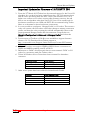


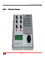
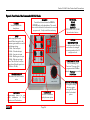
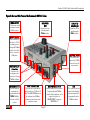

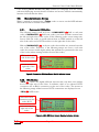

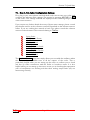
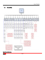


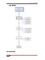

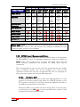
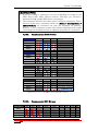
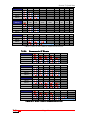


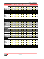
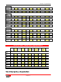
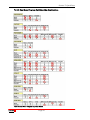

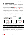


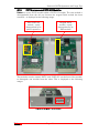
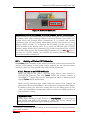


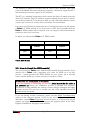
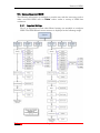
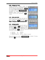
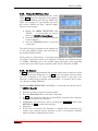
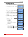
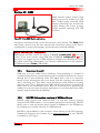


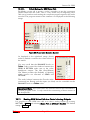

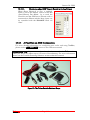

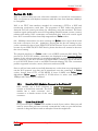


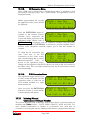
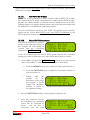

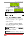

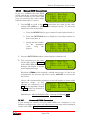
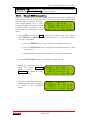
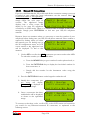

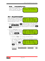
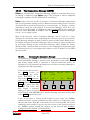


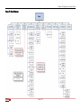


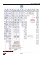

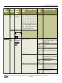

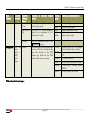

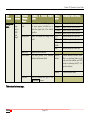

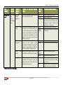

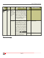
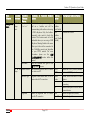
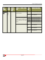


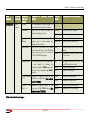
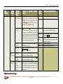
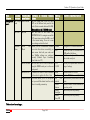
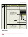
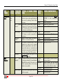
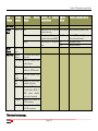
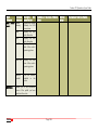

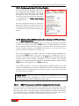
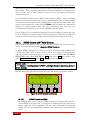
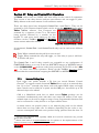

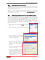


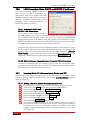


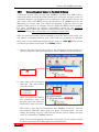
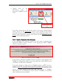
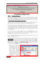

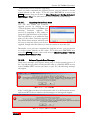


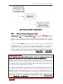


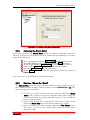

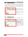
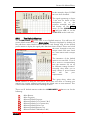
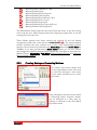
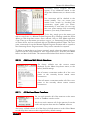

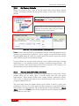
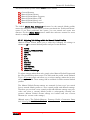

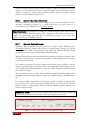

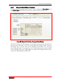

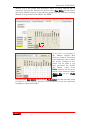
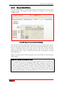
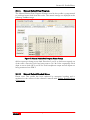
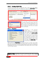
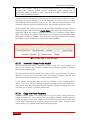
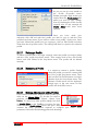
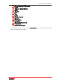
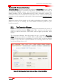
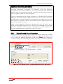


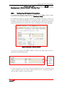

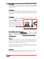


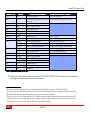

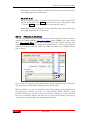
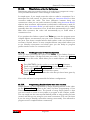
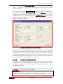
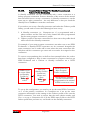

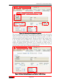
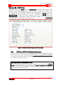
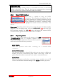
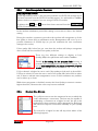


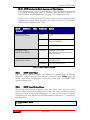


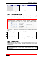

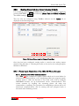
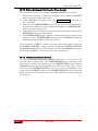
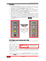
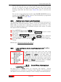
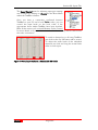
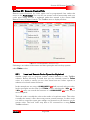


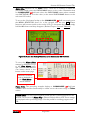

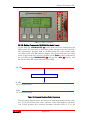
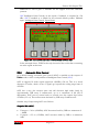


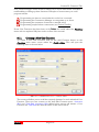


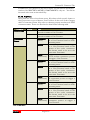
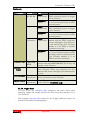

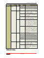
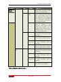
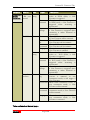
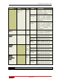


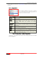


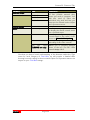

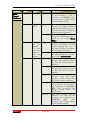
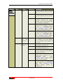
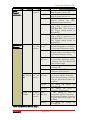
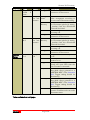
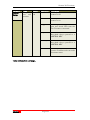
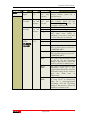
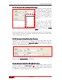
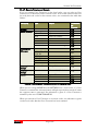
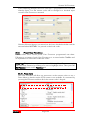
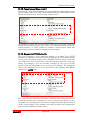
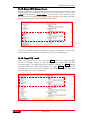

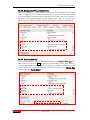


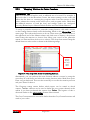

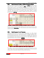
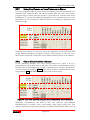


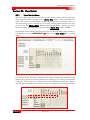


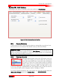
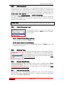
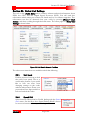

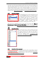
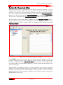

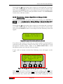
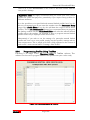
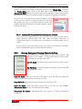
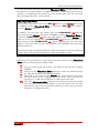


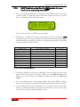


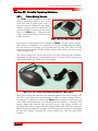

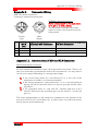
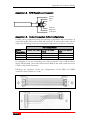
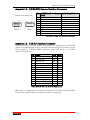
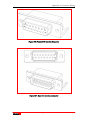

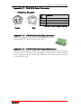
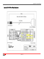


![60 (3) Change any myss[i] calls, where myss is a loop iteration, to](http://vs1.manualzilla.com/store/data/005660192_1-8eea2c3cfc95064c732d161dbe3c262f-150x150.png)