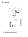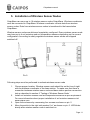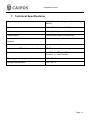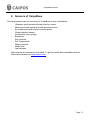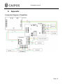
1
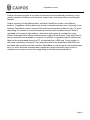
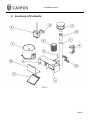
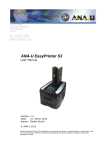
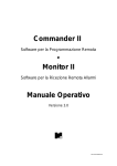
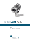
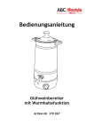
Caipos GmbH Schillerstrasse 5 8200 Gleisdorf, Austria Wireless Soil Moisture and Weather monitoring CaipoBase User Manual This manual is applicable to the following models CaipoBaseV7 CaipoBase Manual © 2013 Caipos GmbH, Austria Caipobase manual Introduction Thank you for purchasing weather station CaipoBase. This manual contains installation and operation instructions. Read this manual carefully before starting and keep the manual for future reference. We, Caipos GmbH, Schillerstr 5, 8200, Gleisdorf, Austria, declare that this product is in compliance with relevant requirements and regulations of directive EN 301 489-1 V1.9.2 ; EN 301 489-7 V1.3.1. Caipos logos, CaipoBase, CaipoWave are trademarks or registered trademarks of Caipos GmbH. Page 2 Caipobase manual Table of Content 1. General Description .............................................................. 4 2. Inventory of Contents ............................................................ 6 3. Installation Guide .................................................................. 8 4. Turning the System On ......................................................... 9 5. Installation of Wireless Sensor Nodes................................. 10 6. Technical Specifications ...................................................... 13 7. Sensors of CaipoBase ........................................................ 17 8. Testing of CaipoBase .......................................................... 15 9. Caipos central web platform ................................................ 16 10. Appendix ......................................................................... 18 Page 3 Caipobase manual 1. General Description Pic.1 Page 4 Caipobase manual Caipos monitoring system is a system of devices for environmental monitoring. It can monitor weather conditions, soil moisture, water level, and many other environmental aspects. Caipos consists of CaipoBase station, wireless CaipoWave nodes, and different sensors. CaipoBase collects data from directly connected sensors and, optionally, from wireless CaipoWave nodes. Internal flash memory allows storing data for up to 2 years depending on number of connected sensors and interval of measurements. Data is uploaded to the central web platform, where free web space is provided for every station. Web application allows instant access to data of last 5 years. Data older than 5 years is archived and available on request. In addition to uploading data to web server, data can be downloaded directly to PC via standard mini USB plug. Every system is delivered completely configured. Only few parts need to be assembled and SIM card with valid data contract must be inserted. CaipoBase is solar powered and maintenance free. For more accurate measurement results rain gauge and solar panel must be cleaned once a year or more often depending on environmental conditions. Page 5 Caipobase manual 2. Inventory of Contents Pic. 2 Page 6 Caipobase manual (1) 1 x Weather Station Pole (2) 1 x CaipoBase (3) 1 x Solar Panel (4) 1 x Caipo Sensor Engine (optional) (5) 1 x Ultrasonic wind Sensor (optional) (6) 1 x Air temperature and relative humidity sensor (optional) (7) 1 x Rain gauge (optional) (8) 1 x Wireless coordinator (optional) (9) 1 x Global radiation sensor (optional) (10) 1 x Front panel (11) 1 x Antenna (12) 2 x Clamps for station (13) 1 x Clamp for Wireless coordinator (optional) (14) 1 x Holder for Ultrasonic wind sensor (optional) 1. Optional parts are included depending on your configuration. For more information please refer to your delivery note. 2. Some sensors included may not be mentioned in this manual. In this case you will receive a separate installation instruction. Page 7 Caipobase manual 3. Installation Guide In order to accurately measure environmental parameters and ensure proper work of solar panel, base station should be installed in an open area without any obstructions. Perform following steps for easiest installation: 1. 2. Prepare an open area, where station will be installed. Prepare the weather station pole (1). Pole must be vertically inserted at least 1 m deep into the soil to ensure long-term stability of the CaipoBase. 3. Push wind speed connector through the wind speed holder and connect it to the wind sensor (5). Rotate connector plug for 1/3 of a turn to lock it in position. 4. Fixate the wind sensor (5) holder to the weather station pole (1) with two M4 screws. Fix the wind sensor to the holder. Red dot on the holder must be aligned with arrow on the wind sensor. 5. Attach the wireless coordinator (8) to the pole (1) with two cable binders. 6. Mount CaipoBase enclosure on the pole with two clamps (12). 7. Attach the solar panel (3) to the CaipoBase holder by tightening 3 M3 screws. 8. Direct CaipoBase with solar panel towards the south to receive maximum solar energy. 9. Rotate ultrasonic wind sensor so that the red dot points towards north. 10. Turn the station on as described in the section 4 of this document Page 8 Caipobase manual 4. Turning On the Base Station Pic 3 Pic.4 1. 2. 3. Prepare a SIM card with valid data contract. Make sure that PIN is deactivated. Unscrew four screws and open the enclosure. Install the SIM card into SIM card holder (3). Page 9 Caipobase manual 4. Connect solar panel (1). Solar panel connector marked SOL. 5. Connect battery connector (2). Battery connector marked BAT. 6. Close the enclosure carefully by tightening 4 screws. Caution: To avoid discharge of the battery do not switch on the device if solar panel is not connected or in shadow. Page 10 Caipobase manual 5. Installation of Wireless Sensor Nodes CaipoBase can serve up to 16 wireless sensor nodes CaipoWave. Wireless coordinator must be connected to CaipoBase. Wireless coordinator collects data from wireless sensor nodes. Data from wireless sensor nodes is transferred to the base station CaipoBase. Wireless sensor nodes are delivered completely configured. Every wireless sensor node may have up to 4 soil moisture and soil temperature sensors depending on the current configuration. According to safety regulations wireless sensor nodes are shipped switched off. Pic 5. Pic 6 Following steps must be performed to activate wireless sensor node 1. 2. 3. 4. Choose proper location. Wireless sensor node should be on the line of sight with the wireless coordinator of the base station. To make sure that there is connection between wireless senor node and base station perform connection test as described in section 6 ‘Testing of Wireless Sensor Node’ Install soil moisture sensors and soil temperature sensors as per requirement. For more information about proper installation of soil moisture sensors visit www.caipos.com Open the enclosure by unscrewing four screws as shown on pic. 5 Move the switch to the right side marked “on” as shown on pic. 6. LED blinks shortly after wireless sensor node is switched on Page 11 Caipobase manual 5. Carefully close the enclosure by tightening 4 screws After wireless sensor node is switched on it will start sending data to CaipoBase within next few hours. Page 12 Caipobase manual 6. Testing of Wireless Sensor Node To test connection between wireless sensor nodes and base station 1. 2. 3. Set the base station into test mode 1.1. Open the enclosure of CaipoBase as described in section 4. 1.2. Press and keep ‘TST’ button on the main PCB until LED displays ‘2’. 1.3. Release ‘TST’ button. If display of the base station is on and three horizontal lines are highlighted in turn base station is in the test mode. Base station exits test mode after one hour or if the ‘TST’ button is pressed again. Open the enclosure of wireless sensor node. Press ‘TST’ button on wireless sensor node. If LED of wireless sensor node blinks after pressing ‘TST’ button connection with base station was successful. Pic 7 If LED does not blink check that sensor node is switched on and properly positioned. See section 5 for more information. Multiple wireless sensor nodes may be tested while the base station is in test mode. Page 13 Caipobase manual 7. Technical Specifications Power supply 6 V, 4,5 Ah Valve Regulated Lead-Acid battery Solar panel 149 x 199 x 3,2 mm, 1,08 W Flash memory 4 Mb (up to 2 years of data) GSM module Dual QUAD BAND GPRS/EDGE Max. number of directly connected sensors 32 Max number of wireless sensors 64 (16 nodes x 4 sensors) Approximate GSM data transfer volume 20 Mb per month Interfaces 1 x USB, 2 x TTL, 1 x SDI-12, 1 x Rain Counter, 1 x Fast Counter Operating temperature -30 – 60 °C Storage temperature -40 – 60 °C Page 14 Caipobase manual 8. Testing of CaipoBase To test connection with the web site Open the enclosure of CaipoBase as described in section 4. Press and keep ‘TST’ button on the main PCB until LED displays ‘1’. Release ‘TST’ button Base station starts testing connection with the web site. Numeric LED display will be switched on. If connection is successful LED display is switched off and data can be checked on web site. For more information refer to section (9) of this document. If connection is not successful blinking error code is shown on LED display. Note the code and contact your supplier. Page 15 Caipobase manual 5. Caipos central web platform For detailed information about Caipos central web platform please refer to CaipoWeb user manual supplied with the station or online at www.caipos.com Creating an Account and Attaching Stations Free web space is provided with every delivered system on http://caipos.com/CaipoWeb/Weather In order to access the data on a user account must be created. Any number of base stations can be attached to a single account. To attach a base station to a web account serial number of station and PIN code should be provided. Serial number and PIN code can be found on the registration card supplied with the base station. Viewing Weather Data After creating a user account and signing in at http://caipos.com/CaipoWeb/Weather, weather data of the first station attached to the account is displayed. Data is shown in graphical and tabular format. CaipoWeb allows viewing data of several stations at the same time. Page 16 Caipobase manual 9. Sensors of CaipoBase Following sensors can be connected to CaipoBase in any combination: - Ultrasonic wind speed and wind direction sensor Mechanical wind speed and wind direction sensor Air temperature and relative humidity probe Global radiation sensor Precipitation (rain gauge) Barometer Soil moisture Soil Temperature Water potential Water level Leaf wetness New sensors are constantly developed. To get the latest about available sensors information please visit www.caipos.com Page 17 Caipobase manual 6. Appendix Connection Diagram of CaipoBase Page 18 Caipobase manual Connection diagram for wireless sensor nodes and Z100, Soil Temperature sensors Connection diagram for wireless sensor nodes and EC5, Soil Temperature sensors Connection diagram for wireless sensor nodes and Watermark sensors Page 19