1
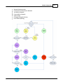
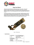
WASP User Manual
Revision: 1.6
(c) 2012 North Pole Engineering, Inc.
2
1
WASP User Manual
Introduction
WASP is a standalone unit providing a bridge for ANT+ devices to communicate wirelessly through
Wi-Fi networks, to other devices on the local network or over the Internet. Utilizing an NPE WiFiIT! module, 8-channel ANT+ receiver, on-board memory, power management circuitry and
rechargeable Li-Ion battery, WASP provides a data gateway for monitoring, recording and
analyzing ANT+ data remotely.
WASP connects ANT+ devices to wireless networks for monitoring and data collection purposes.
For example ANT+ home scales, pulse-oximeter monitors, and blood glucose monitors as well as
heart rate monitors and all other ANT enabled devices are all able to use this bridge module to
communicate their data to central monitoring stations via the WiFi network.
WASP is capable of receiving data wirelessly, from all certified ANT+ devices in the local area that
share the same ANT frequency. ANT+ device date is encapsulated as standard TCP-IP messages,
allowing it to be routed through local networks , through the Internet or directly to any Wi-Fi
connected device. WASP can be configured directly over the network through both TCP and UDP
protocols. WASP is also capable of sending data to any ANT radio in range that is capable of
receiving data packets.
An Application Programmers Interface is available to OEM partners, allowing WASP integration
into custom applications needing wireless connectivity to ANT enabled devices at ranges which
exceed the typical ANT radio reach. WASP Wi-Fi is able to join existing networks with common
security protocols, or it creates it's own Ad hoc network allowing WASPs and application end
point devices (smart phones, tablet computers, Personal Computers, etc.) to join and share
information locally. WASP will run for up to six hours on its internal Li-Ion battery when
operating in Ad hoc mode as the network manager or up to 18 hours when joining an existing
network. Battery life is dependant on the amount of ANT traffic local to the WASP. For fixed
installation environments, WASP can be powered from a USB power source.
In addition to the periodic streaming protocols, WASP supports ANT-FS sessions when coupled
with a Wi-Fi application or web host to manage the authentication, and file transfer requests.
When WASP is configured in ANT-FS mode, it searches for ANT-FS beacons. When a beacon is
found, it commands the device sending the beacon to change frequencies and await the
authenticate command. The Wi-Fi endpoint application or web host is then notified of the
connection and control is passed off to the host device to manage the data transfer. WASP
monitors the transactions assisting in connection management during the transfer process. Once
the transfer is complete (the connection is either closed or lost), it resumes searching for other
ANT-FS devices.
WASP can also be used as a bridge between multiple ANT+ nodes in distributed ANT+ network
topologies. Since ANT+ is a personal area network, it has a typical range of approximately ten to
20 meters. If the ANT+ network is used as a mesh or hub and spoke topology, WASP can join
networks together that would normally not be able to communicate with each other because of
range limitations.
(c) 2012 North Pole Engineering, Inc.
Scope
2
3
Scope
This document provides a general introduction to using WASP. It includes information on button
operations, LED indicators, powering/charging the device, and Wi-Fi configuration.
3
What's New
Here are the updates for the latest release and previous releases.
Installation 1.6.1
1. Functional packet protocol change from point to point packet routing to local area UPD
multicast packets greatly increasing the number of Wi-Fi endpoints capable of receiving data
from a WASP while at the same time reducing the number of transactions required to supply
the data.
2. Support for both TCP and UDP type connections.
3. Enabled TCP connection for managing WASP configuration/control operations to a single
endpoint instead of UDP control from multiple end points requesting control.
4. Singular IP routing entry for supporting connection to web services outside the local Wi-Fi
network.
5. Improved user interface (button/LED) operation
6. Configured network persistence improvements which allow the WASP to reacquire the
network if the connection is lost.
7. Stage 1 implementation of onboard data storage of ANT data.
4
Quick Start Guide
The Quick Start Guide leads you through beginning to use the WASP. It is simple to use, yet
provides all the ANT, ANT+, and ANT-FS functionality you need to work with the ANT enabled
devices.
(c) 2012 North Pole Engineering, Inc.
4
WASP User Manual
Membrane Switch and Label
4.1
Getting Started
Out of the box, the WASP needs to be configured to either join an existing Wi-Fi network, or
create its own network. This guide walks the user through the process of setting up the WASP for
a specific operating environment. Turning WASP on, off or changing operating modes are
performed using the button on the front panel of the device. This button is a membrane switch
so feedback on button presses is provided by the green and red LEDs above the button. The red
LED is on the left side of the label and the green LED is on the right side. The green LED is primary
used to show the WASP is powered on and its operational state. When on steady, WASP is
connected to an infrastructure network or when flashing, WASP has created or joined an Ad hoc
network. Refer to Modes of Operation for additional details on the operating modes.
The red LED is used to provide change of state feedback, indicate the state of the internal battery
charger and to indicate progress when joining Wi-Fi networks. Refer to Modes of Operation for
details on the operating modes of the red LED.
The mini-USB connector on the back of the WASP is used to charge the internal Lithium Ion
battery using either a USB connection on a computer, or a stand-alone wall charger. It can also be
used to configure the WASP via an application running on a computer connected to the USB cable.
The loop at the top of the WASP is used to secure the WASP to any attachment point such as a
lanyard or Velcro strap.
(c) 2012 North Pole Engineering, Inc.
Quick Start Guide
4.1.1
5
WASP STARTUP
The WASP is turned on by pressing the button for 1 second. Once the green LED illuminates,
released the button and the network scanning operation begins looking for the preferred
network. If the button is held at startup for 5 seconds, WASP will enter WPS Operation, indicated
by the green LED dimming. Holding the button for 10 seconds forces WASP to enter the Reset
Configuration Mode.
Network Scanning
Upon startup, WASP searches for its preferred Wi-Fi network. Completion of one scan pass is
indicated by the red LED flashing three times quickly. If the network is not found another scan is
started. This process continues until either the network is found, or the button is pressed a
second time. Pressing the button and holding it until the red LED flashes forces the WASP to
transition to Ad hoc mode.
Network Authentication
Once the preferred network is found, the red LED turns on steady and WASP attempts to join the
network with the appropriate security settings. If the authentication process is successful, the
red LED blinks once and turns off. If the process fails, the authentication process is restarted. This
process repeats until the network is authenticated or the button is pressed and held until the
authentication fails. Pressing the button and holding it until the red LED flashes forces the WASP
to transition to Ad hoc mode.
WPS Mode
If the button is pressed and held for 5 seconds from the OFF state, the WASP enters WPS Mode
after the green LED dims. WPS mode is used in conjunction with a WPS enabled router or access
point to exchange network setup and security information without the need to go through the
configuration utility.
Reset To Factory Defaults
If the button is pressed and held for 10 seconds from the OFF state, WASP resets its internal
configuration table to factory defaults. Refer to the factory defaults section for details on the
specific settings.
Connected To Wi-Fi Network
Once the WASP has connected to the preprogrammed Wi-Fi network, the green LED is illuminated
and the red LED indicates the status of the battery charging.
Connect To An Ad hoc Network
If WASP is commanded to enter the Ad hoc mode, via the button, and it finds an existing Ad hoc
network matching the desired network name (the preferred network name with an "a" prepended to it) it will attempt to join the network and if successful, the green LED flashes at a 3Hz
rate.
Created Ad hoc Network
If the WASP is commanded to enter the Ad hoc mode, via the button, and an existing Ad hoc
network, of the correct name doesn't exist, it creates its own Ad hoc network with a DHCP server
(c) 2012 North Pole Engineering, Inc.
6
WASP User Manual
running. The green LED flashes at a 1Hz rate.
WASP Startup Flowchart
The flowchart below details the possible startup states of the WASP, as described above.
4.1.2
WASP Configuration
WASP is configured using the configuration application, which runs on either an iOS device or a
Windows PC. The device performing the configuration must be on the same Wi-Fi network as the
WASP that is being configured. Out of the box WASP, is setup to join a network with the name "NpeWasp". This network name is preprogrammed and is the default network name that will be
(c) 2012 North Pole Engineering, Inc.
Quick Start Guide
7
restored in the event WASP is reset to its default configuration. This network likely does not
exist in most environments, so WASP needs to be placed into the Ad hoc network creation mode.
Refer to Ad hoc Network Operations for details on entering Ad hoc mode.
Once WASP has created the Ad hoc network, the device that will be used to configure the WASP
needs to join the Ad hoc network. On iOS devices this needs to be performed using the Settings
application of the iPhone, iPad
. If using the Windows config application, the network is
selected from within the application.
The configuration application lists all of the WASPs found on the network. Select one of the
WASPs to configure and select the option to connect to the WASP. Only one device is allowed to
open a connection to a WASP. If another device attempts to open a connection the WASP checks
with the currently connected device to find out if it is still connected and if it is willing to release
the configuration connect. If it is no longer on the network or it is willing to release the
connection the new device is granted access to the configuration interface. Otherwise it is sent a
message indicating the configuration interface is not currently available.
If the configuration connection is established the application then has access to the configuration
settings. A description of the settings is available in the Configurable Hardware Settings section
of this document. The default settings are found in Default Settings.
After the new settings are selected in the user interface, the changes are applied to the WASP by
choosing to apply the settings. When the WASP receives the command to apply the settings, the
internal configuration table stored in non-volatile FLASH memory is updated and the WASP resets
itself and attempts to join the preferred network using the new settings.
IMPORTANT: Power Cycle the WASP after the settings are changed to ensure the new settings are
processed properly by the WASP. There is currently an Issue with the WASP switching from
operating as a DHCP server to receiving its address from a DHCP server. Running through a power
cycle solves this issue.
4.1.3
WASP UDP Multicast Data
Once the WASP has established a network connection, it opens a UDP Multicast address at
239.78.80.1 and sends out a QUERY Response packet for any device subscribed to the address to
receive. It then starts forwarding any ANT message it receives from any ANT transmitter
configured to send on ANT RF channel 57 to the multicast address.
The UDP protocol with a multicast address was chosen for data transmission to allow any device
on the local network to receive the ANT transmissions broadcasted by WASP without generating
multiple UDP packets for each device that desires to receive the data. This allows for a scalable
system of local end points without overwhelming the network.
Additionally, a unique routable address can be provided in the configuration settings table, to
allow the WASP to send data to a specific routable endpoint on an extended network provided
the router or access point for the Wi-Fi network can reach the specified IP address.
4.1.4
WASP UDP Listening Mode
Once the WASP has either joined a Wi-Fi network, or created one, it opens up a UDP listening port
at 17653. If a QUERY command is received the WASP sends out a QUERY response message on the
UDP multicast address providing details about the WASP. These details include the operational
(c) 2012 North Pole Engineering, Inc.
8
WASP User Manual
state of the WASP as well as battery level and version information. Refer to the WASP Packet
Protocol Specification for more details on the packet protocol.
4.1.5
Network Operations
WASP can either join an existing wireless network or create its own Ad hoc network. Both DHCP
and Static IP addressing are supported. When WASP powers up, it looks for the network with the
SSID configured in its settings table. If WASP fails to join the preferred network and is
commanded to create an Ad hoc network through a button press, it either creates an Ad hoc
network using the preferred network name with an "a" pre-pended to the SSID, or it joins an
existing Ad hoc network of the same name.
Preferred Wireless Access Point
WASP will join the Preferred Network when the current WASP device settings match the
detected networks. If DHCP is enabled the WASP expects to receive the IP configuration from the
Access Point (AP). If DHCP is disabled WASP uses the configured static IP address to access the
AP.
Join Ad hoc Wireless Access Point
The WASP joins the Ad hoc network if it finds an Ad hoc network matching the preferred network
name with an "a" pre-pended to the configured network name. If DHCP is enabled it will request
an address from the DHCP server running on the device managing the Ad hoc network. If DHCP is
disabled, the WASP uses the configured Static IP address from the settings table.
Create Ad hoc Non-server Wireless Access Point
If WASP fails to join either the preferred network or an Ad hoc network, it creates its own Ad hoc
network. If DHCP is disabled then WASP creates an Ad hoc network using the configured static IP
address but without a DHCP server running. The default values are listed in Default settings
section.
Create Ad hoc Server Wireless Access Point
If DHCP is enabled, then WASP will create an Ad hoc network using the default DHCP server static
IP address and starts a DHCP server. The DHCP server will run as a simple DHCP server - it does not
maintain a lease table, but simply assigns address sequentially starting with X.X.X.2. It can
provide up to eight addresses. The default values are listed in Default settings section.
4.1.5.1
Special AdHoc DHCP Server Consideration
If the WASP acting as the DHCP server leaves the network, there is no longer a DHCP server for
the network. If another device tries to join this network it will not receive an IP address.
4.2
Charging
WASP provides a mini-USB port to connect to a powered USB port on a computer or using a USB
(5V) wall transformer. This USB port is connected to the integrated Li-ion battery charger, which
monitors the status of the battery and controls the charge state. Once the battery reaches a full
charge, the charger stops the charging process and maintains a full charge level without
overcharging the battery so the WASP can remain connected to power indefinitely.
The red LED is used to provide feedback on the charging state of the WASP, both in the OFF and
ON states. When the WASP is attempting to join a Wi-Fi network, the red LED is used to provide
(c) 2012 North Pole Engineering, Inc.
Quick Start Guide
9
feedback on the progress of the connection process and does not provide the feedback for
battery charging.
When the red LED is flashing the battery is charging. If the LED is a solid red, the battery is fully
charged.
5
Configurable Hardware Settings
There are a number of hardware settings that modify the operation of the WASP. The network
settings, described else where in this document, the configured static IP, and DHCP settings all
affect WASP operation.
5.1
Default Settings
User Setting
Factory Default
Value
Description
WASP Name
17 character MAC
Address of the WASP
The WASP name is a 32 character field used to
provide an ASCII name to identify the WASP in the
QUERY response.
Preferred Network SSID
Preferred Network Security
Preferred Network
PassPhrase
Ad hoc Network Security
Ad hoc Network PassPhrase
NpeWasp
None
12345678
None
1234567800
A 31 character ASCII name used to identify the WiFi network the WASP attempts to join when it is
searching for wireless networks. A standard SSID
is 32 characters but the WASP uses this name to
generate its Ad hoc network by adding an "a" to the
beginning of the name.
The security type used for joining an encrypted
network. Options include WEP, WPA, WPA2 or
None
The preferred network security field is a 64
character field used to support the PassPhrase
required for any of the supported Wi-Fi security
schemes. For WPA or WPA2 the PassPhrase needs
to be between 8 and 32 characters. For WEP it is
either 10 or 26 Hexadecimal characters.
Ad hoc supports either WEP or None for security
type.
WEP security is either 10 or 26 Hexadecimal
characters.
Ad hoc Channel
11
The Wi-Fi channel used by the Ad hoc network. The
valid values are 1-11 with 1,6, and 11 as the
typical non overlapping channels
DHCP
ON
The DHCP selection identifies if the WASP will
attempt to get an address from a DHCP server
when it joins a network or if it starts the DHCP
(c) 2012 North Pole Engineering, Inc.
10
WASP User Manual
server when it creates an Ad hoc network. If DHCP
is turned off, the WASP uses the Static IP address
set in the configuration table.
Static IP Address
192.168.87.1
IP Address used when DHCP is turned off
IP Address used by simple DHCP server for seeding
the address for devices requesting an IP Address
from the server. The first address served with be
incremented by one from the address list.
Subnet Mask
255.255.255.0
Gateway IP
192.168.87.1
IP Binding Address
0.0.0.0
IP Binding Port
Address used to provide a streaming connection
inside or outside the local network. The address
should be routable based on the local network
configuration. This can be customized to meet
customers needs to point to a specific Web host
address for cloud storage applications.
Port used to direct the streaming UDP packets with
operating in streaming mode. This can be
customized to meet customers needs to point to a
specific Web host address for cloud storage
applications.
Streaming
Operational modes supported are Streaming,
Proximity, and Access Point. The proximity mode
also has a range setting that adjusts the distance
a device is detectable from the WASP.
ANT+ Network Key
The default eight byte Network Key can be selected
to be either Public, ANT+, ANT-FS, or custom
Custom ANT Network Key
6
Address used to access addresses outside the
local domain
0
Operational Mode
ANT Network Key Selection
Subnet filter used to identify the ranges of the IP
address that are common to all devices on the
network
0.0.0.0.0.0.0.0
The custom network key is used for proprietary
networks
Modes of Operation
The WASP has operational modes which are selectable via the membrane button located on
the front panel of the device. The button area is defined by the black circle just below the
red and green LEDs. The flowchart below, details how states are entered and exited. The
following modes are supported.
Sleep
WPS Setup
Reset Configuration to Factory Defaults
Network Scanning
(c) 2012 North Pole Engineering, Inc.
Modes of Operation
Network Authentication
Connected to Infrastructure Network
Join Ad hoc Network
Create Ad hoc Network
Power Down
Charging/Charged Indicator
Error State Reporting
(c) 2012 North Pole Engineering, Inc.
11
12
6.1
WASP User Manual
Sleep Mode
When the WASP is off, it is in the lowest power mode or sleep state. This is indicated by both
LEDs turned off. In this mode, the WASP awaits a command to either transition to the Charging
Indicator or Network scanning modes. The Charging Indicator state is entered when a USB power
source is plugged in. Network scanning begins when the button is pressed.
When the button is pressed while the WASP is in the sleep state, the button needs to be held for
approximately three-quarters of a second. This delay prevents the WASP from inadvertently
turning on if the button is bumped. WASP is returned to sleep mode with a button press and hold
of 1 second from one of the connected states ( Infrastructure or Ad hoc).
6.2
Charging Indicator
The red LED is used primarily to indicate the state of the battery charging. When the unit is off,
and the powered USB cable is connected, the red LED with either be on steady, indicating a fully
changed battery, or it will be flashing once a second, indicating the battery is charging. The WASP
can remain plugged in, at all times, to maintain the battery in the maximum charge state. At
times, the solid red will transition to blinking red indicating the battery voltage has dropped to
the point where the battery supervisor needs to perform a maintenance charge cycle.
The red LED also indicates the status of the battery charging once the WASP has transitioned
through the connection sequence and has joined or created a network (infrastructure or Ad hoc).
After the connection sequence has completed the LED once again indicates the battery charging
state.
6.3
Startup Mode
WASP enters Startup Mode whenever one of the two startup events occurs.
Powered USB connected
Button pressed for 1 second
6.4
USB Power
When a 5V 100ma (min) powered USB cable is inserted while the WASP is in sleep mode, the
module wakes up and enters the charging state. No other operations are performed and the
green LED remains off. The red LED blinks at a slow rate indicating charging is active, or lights solid
red, indicating the battery is fully charged.
6.5
Button Pressed
If the button is held for 1 second the green LED turns on and the WASP enters the infrastructure
Wi-Fi network scanning mode. While the WASP is starting up with the green LED active, the red
LED no longer provides the battery status with the USB cable inserted. Instead it uses the red LED
to indicate the status of the network connection attempts.
(c) 2012 North Pole Engineering, Inc.
Modes of Operation
6.6
13
Network Scanning
The first operation performed by the WASP upon startup is to begin searching for the configured
Wi-Fi network SSID. This is indicated by the red LED flashing rapidly three times each time a scan
is completed. If the preferred network is found, the red LED turns on solid red while network
associating is completing. If the preferred network is not found, a new scan is initiated indicated
by the three rapid flashes of the red LED upon completion. This process continues until either the
preferred network is found, or the button is held during the three rapid LED flashes. If the button
is held, the WASP stops looking for the preferred network and instead attempts to join or create
an Ad hoc network with the name of the preferred network with an "a" pre-pended to the name.
Refer to the Ad hoc network section for a description of Ad hoc network operations.
6.7
Network Authentication
If the network has security enabled, authentication will take a few seconds. If the authentication
process is successful, the red LED blinks and goes out. At this point the red LED resumes reporting
the status of the battery charging.
If the network fails to authenticate, the red LED will illuminate again and a new attempt to join
the network begins. This process continues until either the preferred network is joined or the
button is pressed and held at the end of the authentication process. If the button is held, the
WASP stops the authentication process and instead attempts to create or join an Ad hoc network
with the name of the preferred network with an "a" pre-pended to name. Refer to the Ad hoc
network section for a description of Ad hoc network operations.
6.8
AdHoc Network Operations
Ad hoc mode is indicated by the green LED flashing at a slow 1Hz rate, or a quick 3Hz rate. The
slow rate indicates WASP has created the Ad hoc network and is managing the Ad hoc network. It
also runs a simple DHCP server, if enabled, that is capable of serving up to eight IP addresses.
Note, that the simple DHCP server does not maintain a lease table. This means that any device
that requests an address and looses the connection will receive a different address when it
attempts to reconnect. Also, if the WASP creating the Ad hoc network is power cycled, it will
restart the DHCP IP address assignments from the initial IP address. This means devices that join
the network can receive the same address as other devices that had joined the network before
the WASP was power cycled.
The fast blink rate indicates the WASP has joined an existing Ad hoc network created by another
device and has received an IP address from the DHCP server managed by the other device.
Ad hoc mode can be used to set configure WASP parameters such as the primary network settings
and modes of operation via Wi-Fi, when connected to a device running the configuration
application. Configuration parameters can also be modified by plugging the WASP into a
computer using the mini-USB cable, bypassing the Wi-Fi connection.
Since the WASP has the ability to create its own Ad hoc network, it is capable of running in
environments typically not available to other Wi-Fi based devices. For example, if a user is in an
area where Wi-Fi is not available, the network created by the WASP can be joined by Wi-Fi
enabled devices, such as a smart phone, tablet computer or a PC with a Wi-Fi card, to receive data
sent by the WASP. Simply create the Ad hoc network with the WASP and join the network with
(c) 2012 North Pole Engineering, Inc.
14
WASP User Manual
the collection device. The WASP used to create the network will drain its battery faster than a
WASP that joins the created network because the WASP maintaining the network cannot take
advantage of the power saving features of the Wi-Fi module.
6.9
WPS Operation
The WASP can join a Wi-Fi network via WPS (Wi-Fi Protected Setup), if the wireless Router or
Access Point is capable if participating in WPS operations. Wi-Fi Protected Setup (WPS) is a
computing standard for easy and secure establishment of a wireless network.
To initiate WPS mode, from an OFF state, press and hold the button for five seconds waiting for
the green LED to dim. Once the dimming occurs the button is released and WPS mode
commences with the Router or Access Point. A simultaneous operation needs to be performed
on the Router or Access Point. Refer to the documentation for that unit for details on entering
WPS mode.
If the button is held for 5 seconds after the green LED dims, WASP will reset its configuration
settings to the factory defaults.
6.9.1
WPS FAIL Mode
When WPS fails, the green LED flashes indicating the failure.
6.10
Reset Settings
If the button is pressed and held for 10 seconds from an OFF state, the WASP resets its
configuration settings to factory defaults. The reset is confirmed by the red LED illuminating 5
seconds after the green LED dims during the button hold operations.
6.11
Reset Configuration Mode
The WASP will enter the Reset Configuration Mode whenever the button is held past 10 seconds
from the exit of SLEEP mode.
6.12
Power Down Mode
To turn WASP off, it must be in an operational state, connected to an infrastructure or Ad hoc
network. When it is in either of these states, hold the button for 1 second. When the WASP
detects this condition, it flashes the red LED twice and powers down turning off the green LED. If
the USB power is applied, the red LED will either flash or remain light depending on the status of
the battery charger.
If WASP is either scanning for a network or attempting to authenticate, the user must first press
and hold the button to exit either mode. This is indicated by a double flash of the red LED
indicating positive feedback of the button press. Currently the scan and network authentication
are blocking operations which cannot be interrupted by a button press. Once the button press is
recognized, the WASP enters Ad hoc mode and then it will respond to the button press to turn the
unit OFF.
(c) 2012 North Pole Engineering, Inc.
WASP Hardware
7
WASP Hardware
7.1
Wi-Fi Key Features
FCC/IC/WiFi Certified
802.11 b/g/n Compatible (Requires 802.11b enabled on network)
Dual ARM7 Processors for application and networking
Small Form Factor (1.28” x 0.9” x 0.143”)
Security: WEP128, WPA-PSK and WPA2-PSK (TKIP / AES)
-40 to +85 °C Operating Temperature Range
5 Volt USB power
Splash Resistant Case
Integrated attachment loop
7.2
ANT Key Features
2.4GHz worldwide ISM band
78 selectable RF channels (2403 to 2480MHz)
Ultra low power operation
Integrated F antenna
Broadcast, acknowledged, or burst data transmissions
ANT channel combined message rate up to 190Hz (8byte data payload)
Minimum message rate per ANT channel 0.5Hz
Burst transfer rate up to 20Kbps (true data throughput)
Up to 8 ANT channels
Up to 3 public, managed and/or private network keys
1 Mbps RF data rate, GFSK modulation
-40°C to +85°C operating temperature
Radio regulatory approval for major markets
RoHS compliant
Specific Radio Features
Background scanning
Continuous scanning mode
High density node support
(c) 2012 North Pole Engineering, Inc.
15
16
WASP User Manual
Improved channel search
Channel ID management
Improved transmission power control
Frequency agility
Proximity acquisition
The complete description of ANT message protocol is found in the document “ANT Message
Protocol and Usage”. This document is available on www.thisisant.com.
7.3
User Interface
The WASP has a integrated membrane switch which includes a button, a green LED, a red LED built
into the graphics overlay. See Modes of Operation for more information.
7.4
Charger interface
The WASP provides a mini-USB port to connect to a powered USB port on a computer or a USB (5V)
wall transformer. This USB port is connected to an integrated Li-ion battery charger.
The red LED is used by the WASP to indicate different charging modes.
8
WASP Protocol
Refer to the WASP Packet Protocol Specification for a detailed description of the communications
protocol used to interface with the WASP.
9
Definitions
WASP Client Device is defined as the programming interface the WASP Packet Protocol
communicates with and would be running in the application device.
WASP Protocol Commands are defined as the protocol packets with the specific command
code in byte 2 of the packet. There are parts of the packet that are defined common across all
the protocol commands. Also, there is specific packet sections defined for each protocol
command.
WASP API Packet Commands are defined as the packet commands being received by the
WiFi-Basic code from the application device.
WASP Asynchronous Packet Commands are defined as the packet commands being created
by the WiFi-Basic code asynchronously and sent to the application device.
WASP Response Packet Commands are defined as the packet commands returned directly by
the WiFi-Basic code after receiving one of the WASP API packet commands.
Packet Type identifier is defined as bytes 0 and 1 of each WASP Packet and are defined as
ASCII characters “A” followed by “N”.
Packet Command ID is defined as an incrementing count created by the initiator of the packet,
and returned in byte three of the response packet commands.
(c) 2012 North Pole Engineering, Inc.
Definitions
MAC address is defined as the MAC of either the application device or the WASP device
depending on who is the sending device.
ANT Message Protocol is defined in ANT_Message_Protocol_and_Usage_Rev_4.1.pdf
document provided by Thisisant.com.
Connection ID (CID) as used in WiFi-Basic, is synonymous with socket.
(c) 2012 North Pole Engineering, Inc.
17