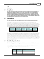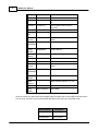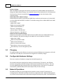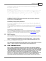
1
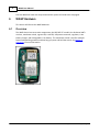
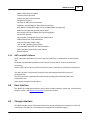
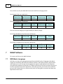
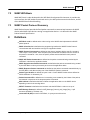
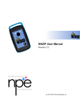
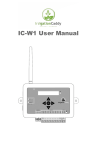
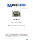
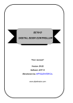
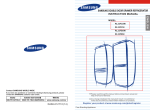
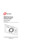
WASP User Guide
Version 1.0.0
(c) 2011 North Pole Engineering, Inc.
I
WASP User Manual
Table of Contents
Foreword
0
Part I Introduction
1
Part II Scope
1
Part III What's New
1
Part IV Modes of Operation
1
1 Sleep Mode
................................................................................................................................... 2
2 Startup...................................................................................................................................
Mode
2
3 Reset Configuration
...................................................................................................................................
Mode
2
4 On Mode
................................................................................................................................... 4
5 Power Down
...................................................................................................................................
Mode
4
Part V Quick Start Guide
4
1 Getting...................................................................................................................................
Started
4
WASP STARTUP.......................................................................................................................................................... 5
WASP UDP Listening
..........................................................................................................................................................
Mode
5
Client Device Query
..........................................................................................................................................................
Request
5
WASP Query Response
.......................................................................................................................................................... 5
Client Device Connect
..........................................................................................................................................................
Request
6
WASP Connect..........................................................................................................................................................
Response
6
Client Device Disconnect
..........................................................................................................................................................
Request
6
WASP Disconnect
..........................................................................................................................................................
Response
6
2 Default...................................................................................................................................
Settings
6
3 Charging
................................................................................................................................... 7
4 Configurable
...................................................................................................................................
Hardware Settings
7
5 Network
...................................................................................................................................
Operations
7
DHCP Operations
.......................................................................................................................................................... 8
Special AdHoc
.........................................................................................................................................................
DHCP Server Consideration
8
6 WASP Heartbeat
...................................................................................................................................
Process
8
Part VI WASP Hardware
9
1 Overview
................................................................................................................................... 9
2 WiFi-IT!
...................................................................................................................................
Module
10
WiFi-IT! Key Features
.......................................................................................................................................................... 10
3 ANT Module
................................................................................................................................... 11
Ant AP2 Features
.......................................................................................................................................................... 11
ANT+ and ANT+
..........................................................................................................................................................
Alliance
12
4 User Interface
................................................................................................................................... 12
5 Charger
...................................................................................................................................
interface
12
(c) 2011 North Pole Engineering, Inc.
Contents
Part VII WASP Software
II
13
1 WiFi-Basic
...................................................................................................................................
Language
13
2 WASP...................................................................................................................................
WiFi-Basic
14
3 WASP...................................................................................................................................
Packet Protocol Summary
14
Part VIII Definitions
Index
14
0
(c) 2011 North Pole Engineering, Inc.
II
1
1
WASP User Manual
Introduction
WASP is a standalone unit providing a bridge for ANT+ devices to communicate wirelessly through
Wi-Fi networks to other devices or over the Internet. Integrating an NPE WiFi-IT! module, 8channel ANT+ receiver, power management circuitry and rechargeable Li-Ion battery, WASP
provides a data gateway for monitoring, recording and analyzing ANT+ data remotely. The water
resistant case features an integrated loop for securing the unit to the user while in use. WASP
receives data from connected ANT+ devices and translates the data into Wi-Fi packets, making it
available to any Wi-Fi connected device. The WASP Application Programmers Interface is an open
API that is used by developers to integrate WASP into ANT+ applications. WASP can operate for
up to 6 hours on a single charge, or continuously plugged into a computer USB port or wall USB
power supply.
WASP connects ANT+ devices to a wireless network for monitoring and data collection purposes.
For example ANT+ home scales, pulse-oximeter monitors, and blood glucose monitors are all able
to use this bridge module to communicate their data to central monitoring stations via the Wi-Fi
network.
WASP is also usable as a bridge between multiple ANT+ nodes in distributed ANT+ network
topologies. Since ANT+ is a personal area network, it has a typical range of approximately two
meters. If the ANT+ network is used as a mesh or hub and spoke topology, WASP can join
networks together that would normally not be able to communicate with each other because of
range limitations.
2
Scope
This document provides a general introduction to using the WASP interface.
3
What's New
Here are the updates for the latest release and previous releases.
Installation 1.4.2
WASP Wifi-Basic
1. First release of the WASP code.
4
Modes of Operation
The WASP device has a number of operation modes.
Sleep
STARTUP
WPS
Reset Configuration
(c) 2011 North Pole Engineering, Inc.
Modes of Operation
2
ON
Power Down
4.1
Sleep Mode
The WASP device starts in SLEEP mode. Power is applied to the device whenever the battery is
installed or the USB cable is plugged into a 5V supply. SLEEP mode is a low power mode that
cycles every 30 seconds. Every 30 seconds it will wake up and check for two alarms and a GPIO
input. The first alarm is attached to the button push. The second alarm is attached to the charge
line of the battery charger. The GPIO line detects when power is applied using the USB cable. Any
of these three actions will move the device to STARTUP mode.
4.2
Startup Mode
The WASP device will enter Startup Mode whenever one of the three startup events occurs.
In this mode the power detection circuit is checked. When it is found active then it will
automatically enter ON Mode. This always ON Mode sets the green LED to a solid on state. This
always on mode will also set the red LED based on the charging state. If the battery is low enough
the charger will be active and the red LED will flash the Charging flash rate. Once the battery is
fully charged the red LED will be changed to a solid on state. The Charging Flash rate is defined as:
ledhicnt (100
ledperiodcnt
ledcntsave
ledoffcnt
ledrepeatsave
milliseconds) (100 milliseconds) (count) (100 milliseconds)
(count)
10
20
4
0
10
When power is not being applied the change from Startup Mode to On Mode will occur when the
button is pushed and held for a minimum of one second. After one second the WASP will start
normal On Mode unless the button is held for a total of 5 seconds from the exit of SLEEP mode. If
button is released before the 5 seconds then the WASP will remain in normal On mode. If button
continues to be held past the 5 seconds the WASP mode will change to WPS mode. The green LED
will be in solid on state as soon as the WASP device enters the On Mode. The red LED will be off
when on battery only mode.
4.3
Reset Configuration Mode
The WASP will enter the Reset Configuration Mode whenever the button is held past 10 seconds
from the exit of SLEEP mode.
In Reset Configuration Mode the WASP will reset certain configuration variables back to the
original values. These variables are listed in the table below:
Variable
Default Value
DHCP
1
IP_ADDRESS 192.168.20.1
(c) 2011 North Pole Engineering, Inc.
Definition
DHCP active
Static IP address when DHCP is
3
WASP User Manual
Variable
Default Value
Definition
turned off.
Static Subnet when DHCP is turned
off.
Static IP address when DHCP is
turned off.
SUBNET
255.255.255.0
GATEWAY
192.168.20.1
Primary
SSID
Primary
Security
Primary
PASSPHRAS
E
Primary
WEPKEY
Primary
Channel
WASP_AP
Primary Wireless AP SSID
NONE
"0000000000"
Primary Security Mode (See table
below)
Primary WPA Passphrase
"0000000000"
Primary WEP KEY
6
Primary Channel (options: 1, 6, 11)
AdHoc SSID
AdHoc
Security
AdHoc
PASSPHRAS
E
AdHoc
WEPKEY
AdHoc
Channel
WASP
NONE
"0000000000"
AdHoc Wireless AP SSID
AdHoc Security Mode (See table
below)
AdHoc WPA Passphrase
"0000000000"
AdHoc WEP KEY
6
AdHoc Channel (options: 1, 6, 11)
WASP
NAME
<MAC ADDRESS> WASP NAME
After the values are returned to their default state, the WASP will set the SLEEP mode and return
to main loop. From the main loop the WASP WiFi-Basic code will enter the SLEEP mode.
Security Modes
Discriptions
NONE
No Security turn
on.
WPAPERSONAL
WPA Personal
(c) 2011 North Pole Engineering, Inc.
Modes of Operation
4
Security Modes
Discriptions
Security Protocol
WPA2PERSONAL WPA2 Personal
Security Protocol
WEPOPEN
WEP Open Security
Protocol
WEPSHARED
WEP Shared
Security Protocol
AUTO
Not supported
WPAENTERPRISE Not supported
WPA2ENTERPRISE Not supported
4.4
On Mode
The WASP device will enter On Mode from Startup Mode, WPS Mode, and WPS Fail Mode. In the
On Mode the green LED will be set to a solid on state and the red LED will depend on the charging
line. In the On Mode the WASP device will run the main network initialization and the main code
loop. When in the On Mode the button is pushed and held for a minimum of one second the
WASP will enter the Power Down Mode.
4.5
Power Down Mode
The WASP device will enter the Power Down Mode when in the On Mode the button is pushed
and held for a minimum of one second. In this mode the WASP WiFi-Basic code will set the SLEEP
mode and prepare the hardware for sleep.
Once the hardware is ready the green and red LED will be in a solid off state and the WASP device
will enter sleep.
5
Quick Start Guide
Quick Start Guide leads you through beginning to use the WASP and the WASP Packet Protocol. It
is simple to use, yet provides all the ANT+, ANT FS and FIT+ functionality you need to work with
the ANT+ devices.
5.1
Getting Started
The WASP device and WASP WiFi-Basic code does not startup sending data to WIFI radio. It waits
for a protocol initialization process to be started by the client device. There are a set of command
and responses that make up this protocol initialization process. This process has these steps.
1. WASP STARTUP
2. WASP UDP Listening Mode
3. Client Device Query Request
4. WASP Query Response
5. Client Device Connect Request
(c) 2011 North Pole Engineering, Inc.
5
WASP User Manual
6. WASP Connect Response
7. Client Device Disconnect Request
8. WASP Disconnect Response
5.1.1
WASP STARTUP
The WASP startup process contains a number of elements related to the hardware. Each WASP
device contains a button, one green LED, one red LED, a battery, an ANT chip, a WIFI-IT! chip, a
charging circuit, and a USB port for power. The user interface is made up of the button, the two
LEDs, and the USB port. See the rest of the WASP User Guide for more information on the WASP
hardware and how to use it. In order to power up the device, the user needs to push and hold the
button for one second. After one second the green LED would turn on. At this point the WASP
device is on and ready to enter step 2. The user could continue to hold the button down for a total
5 seconds from the power up state, then the WASP device would enter the WPS setup mode. In
this mode the green LED would flash at a specific rate and pattern to give the user feedback. In
the WPS mode, the user would then enable the other WPS device. After this the WPS process is
run to exchange the security information. When the WPS process completes successfully it will
return to the running state and the green LED would return to a steady on mode. The user could
also continue to hold the button down for an additional 5 seconds then the WASP device would
enter the reset configuration mode. This is a total of 10 seconds from the power up state. In this
mode, certain of the WASP security and configuration information would be reset to the original
state. See Reset Configuration Mode. The red LED has a number of functions. When running and
not powered through the USB port the red LED is off. When the WASP is plugged into the USB and
charging the red LED will be flashing in a specific rate and pattern. Once the WASP is plugged in
and fully charged the red LED will return to a solid on mode. There are a number of errors the
device could enter. These are explained in the WASP User Guide. The errors will also drive the
red LED with different patterns.
5.1.2
WASP UDP Listening Mode
The WASP will enter the UDP Listening mode as soon as the button is held for one second after
power on. The WASP will either join an existing network or create an AdHoc network. In this
mode, the WIFI device next starts a UDP listening on port 17653. The WASP device then starts
waiting on WASP protocol command CODE_QUERY_REQ (0x42) to be received.
5.1.3
Client Device Query Request
The client device when started up will send the WASP protocol command CODE_QUERY_REQ
(0x42) on the current network SSID. The client device will broadcast on the particular subnet of
interest.
5.1.4
WASP Query Response
Once the WASP WiFi-Basic code sees the CODE_QUERY_REQ (0x42) on the current network SSID it
will respond with the CODE_QUERY_RESP (0x43). In this packet the current number of CID spots
available would be returned in byte 24 of WASP packet. It also will return the current WASP name
string. The default until changed is the WASP device MAC address.
(c) 2011 North Pole Engineering, Inc.
Quick Start Guide
5.1.5
6
Client Device Connect Request
The client device receives the CODE_QUERY_RESP (0x43), checks for available slots, and then
determines whether to connect or not. If the device wants to connect it then sends the command
CODE_CONNECT_CMD (0x40).
5.1.6
WASP Connect Response
The WASP WiFi-Basic code then receives the CODE_CONNECT_CMD (0x40) and returns the
CODE_CONNECT_CMD_RESP (0x41). The WASP WiFi-Basic code will also save the CID for this client
device and will include it in the current device send list. At this point the WASP device and the
client device are connected and ready to do other protocol packets. The client device will need to
respond to the HEARTBEAT commands received from the WASP device.
The CODE_CONNECT_CMD_RESP (0x41) returns a number of bytes that contain the current setup
values. See the WASP Packet Protocol document for the information being returned in this
packet.
5.1.7
Client Device Disconnect Request
When the client device determines it want to disconnect from this WASP device, it can send the
command CODE_DISCONNECT_CMD (0x4C).
5.1.8
WASP Disconnect Response
When WASP WiFi-Basic code receives the command CODE_DISCONNECT_CMD (0x4C), it will
respond with the command CODE_DISCONNECT_CMD_RESP (0x4D). The code will then remove
the specific client device CID from the list of attached devices.
5.2
Default Settings
The WASP uses a number of default WIFI settings on initial startup.
Project Configuration Settings (PCP)
The project configuration settings are loaded when the WASP WiFi-Basic code is loaded.
The static IP configuration is used when DHCP is turned off. They are set in the PCP as follows:
Static IP: "192.168.20.1"
Static Subnet: "255.255.255.0"
Static Gateway: "192.168.20.1"
Primary Wireless Access Point (WAP) is used when the WASP connects to an Access Point (AP).
The PCP settings for the Primary WAP are as follows:
Primary SSID: WASP_AP
Primary Channel Number: 6.
Primary Security Mode: NONE.
AdHoc WAP is used when the WASP does not detect and connect to a Primary WAP. The PCP
settings for the AdHoc WAP are as follows:
AdHoc SSID: "WASP"
AdHoc Channel Number: 6
AdHoc Security Mode: NONE.
(c) 2011 North Pole Engineering, Inc.
7
WASP User Manual
Runtime Settings
When the WASP is running the client device and send a SET_CONFIG (0xB4) command that can
change the WASP default settings. See the WASP Packet Protocol document for a full description
of what can be set by this command. See Network Operations for more description of the
network settings.
AdHoc DHPC Server Default Settings
AdHoc DHCP Server WAP is used when the WASP does not detect and connect to a Primary WAP
or a Join AdHoc WAP and DHCP is enabled. The default settings for the AdHoc DHCP Server WAP
are as follows:
AdHoc SSID: "WASP"
AdHoc Security Mode: NONE.
AdHoc Channel Number: 6.
Server IP: "192.168.21.1"
Server Subnet: "255.255.255.0"
Server Gateway IP: "192.168.21.1".
AdHoc Non-Server Default Settings
AdHoc non-server WAP is used when both the Primary WAP and the Join AdHoc WAP fail and
DHCP is disabled. The default settiings for the AdHoc non-server WAP are as follows:
AdHoc SSID: "WASP"
AdHoc Security Mode: NONE.
AdHoc Channel Number: 6.
Static IP: Current static IP value.
Static Subnet: Current static subnet value.
Static Gateway: Current static gateway value.
5.3
Charging
The WASP provides a mini-USB port to connect to a powered USB port on a computer or a 5V wall
transformer. This USB port is connected to an integrated Li-ion battery charger.
5.4
Configurable Hardware Settings
There are a number of hardware settings that the WASP depends on.
The network settings are described else where in this document. The static IP, the different
wireless access points, and DHCP settings all affect how the WASP device connects. There are
also some WASP WiFi-Basic settings that can be configured from a client device. The protocol
command SET_CONFIG (0xB4) can be used to adjust many of these settings.
5.5
Network Operations
The Wasp can either join an existing wireless network or create its own if it cannot join an
existing network. Both DHCP and static IP modes are supported as well. When the Wasp powers
up, it looks for the network with an SSID value configured as the primary SSID. If the Wasp fails to
(c) 2011 North Pole Engineering, Inc.
Quick Start Guide
8
join the primary network it then either creates an AdHoc network called WASP, or joins an
existing WASP AdHoc network.
Primary Wireless Access Point
The WASP will join the Primary WAP when the current WASP device settings match that mode. If
DHCP is enabled the WASP device will expect to receive the IP configuration from the Access
Point (AP). If DHCP is disabled then the WASP device will use the current static IP configuration
to access the AP. The WASP device will link using the three channel values of 1, 6, and 11 in
order.
Join AdHoc Wireless Access Point
The WASP will join the AdHoc WAP if WASP device DHCP is active and there is a DHCP server
currently running on the AdHoc network.
Create AdHoc Non-server Wireless Access Point
At this point, if the WASP device fails to join either the Primary WAP or the AdHoc WAP, it will
create an AdHoc network.
If DHCP is disabled then the WASP device will create an AdHoc network using the current static IP
configuration but without a DHCP server running. The default values are listed in Default settings
section.
Create AdHoc Server Wireless Access Point
If DHCP is enabled then the WASP device will create an AdHoc network using the default DHCP
server static IP configuration and starts a DHCP server running. The DHCP server will run as any
simple DHCP server in a AP mode. The default values are listed in Default settings section.
5.5.1
DHCP Operations
If DHCP is enabled the Wasp will attempt to join the primary network and request an IP address
from a DHCP server. If the join fails it then will attempt to join the WASP network if it exists and
expect to get an address from the Wasp that is running the DHCP server. If it fails to join that
network, it then starts its own DHCP server and creates the Wasp network as the DHCP server.
5.5.1.1
Special AdHoc DHCP Server Consideration
If the Wasp acting as the DHCP server leaves the network, there is no longer a DHCP server for the
network. If another device tries to join this network it will not receive an address.
5.6
WASP Heartbeat Process
Once the WASP is powered up and connected to a client device it then starts up a HEARTBEAT
process that will wait for 5 minutes looking for activity. Every 5 minutes the WASP WiFi-Basic code
will send out a HEART_BEAT_MSG (0x4A). The WASP will then wait for a HEART_BEAT_RESP (0x4B).
When the WASP either receives the response or there are other activities either from the client
devices or the ANT chip, the WASP code reset the HEARTBEAT. If after 5 minutes the code
determines there has been zero activity the HEARTBEAT process moves to HEARTBEAT step 2 and
starts sending the HEART_BEAT_MSG (0x4A) every 1 minute. The WASP code will look for a
response back within 10 of these commands, if it has not received a response in this amount of
(c) 2011 North Pole Engineering, Inc.
9
WASP User Manual
time the WASP will enter the sleep mode and the system will need to be setup again.
6
WASP Hardware
This section will discuss the WASP Hardware.
6.1
Overview
The WASP device has seven main components, the NPE WiFi-IT! module, the 8-channel ANT+
receiver, membrane switch, a green LED, a red LED, USB power connector, regulator, Li-Ion
battery charger, and rechargeable Li-Ion battery. The membrane switch is used for multiple
functions depending on when and how long you press and hold the switch. See Modes of
Operation for more information.
Inside Hardware View
(c) 2011 North Pole Engineering, Inc.
WASP Hardware
10
Membrane Switch and Label
6.2
WiFi-IT! Module
The WiFi-IT! wireless module is a low cost, easy to integrate, robust solution for providing Wi-Fi®
connectivity for embedded devices. The WiFi-IT! family of modules is perfectly suited for creating
a wide variety of wireless applications including sensor-based networks that leverage the
existing 802.11 wireless infrastructure. The module combines two ARM7 processors, an RF
transceiver, 802.11 MAC, FLASH and SRAM memories with a wide range of interfaces including,
two UARTs, two SPI (master and slave), I2C, Digital, Analog and Pulse Width Modulated (PWM)
outputs creating a full system on a chip (SoC).
The WiFi-IT! module meets FCC/IC regulatory certification and is fully compliant with EU and
R&TTE Directive for Radio Spectrum. It is also pre-scan compliant with Japan Radio Type Approval
(i.e. TELEC).
6.2.1
WiFi-IT! Key Features
FCC/IC/WiFi Certified
802.11 b/g/n Compatible
Dual ARM7 Processors for application and networking
Small Form Factor (1.28” x 0.9” x 0.143”)
Timer and Event Triggered Auto-reporting Capability
Analog, Digital, Serial and PWM Interfaces
Real-Time Clock with Alarm Inputs and Control Outputs
Security: WEP128, WPA-PSK and WPA2-PSK (TKIP / AES)
WLAN and TCP/IP Stacks Built-in
(c) 2011 North Pole Engineering, Inc.
11
WASP User Manual
UART Interfaces Support Hardware Flow Control
-40 to +85 °C Operating Temperature Range
3.3 Volt Nominal Operating Voltage
6.3
ANT Module
ANT™ is a practical wireless sensor network protocol running on 2.4 GHz ISM band. Designed for
ultra low power, ease of use, efficiency and scalability, ANT easily handles peer-to-peer, star,
tree and practical mesh topologies. ANT provides reliable data communications, flexible and
adaptive network operation and cross-talk immunity. ANT’s protocol stack is extremely compact,
requiring minimal micro controller resources and considerably reducing system costs.
ANT provides carefree handling of the Physical, Network, and Transport OSI layers. In addition, it
incorporates key low-level security features that form the foundation for user -defined,
sophisticated, network-security implementations. ANT ensures adequate user control while
considerably lightening computational burden in providing a simple yet effective wireless
networking solution.
ANT supports public, managed and private network architectures with 232 uniquely addressable
devices possible, ensuring that each device can be uniquely identified from each other in the
same network.
ANT is proven with an installed base of over four million nodes in ultra low power sensor network
applications in sport, fitness, home and industrial automation. The ANT solutions are available in
chips, chip sets and modules to suit a wide variety of application needs.
Incorporated in AP2 product family are several ANT core stack enhancements :
Background scanning
Continuous scanning mode
High density node support
Improved channel search
Channel ID management
Improved transmission power control
Frequency agility
Proximity acquisition
The complete description of ANT message protocol is found in the document “ANT Message
Protocol and Usage”. This document is available on www.thisisant.com.
6.3.1
Ant AP2 Features
2.4GHz worldwide ISM band
78 selectable RF channels (2403 to 2480MHz)
(c) 2011 North Pole Engineering, Inc.
WASP Hardware
12
20mm x 20mm drop-in module
Ultra low power operation
Simple sync/async serial interface
Integrated F antenna
On board 32.768 kHz crystal oscillator
Broadcast, acknowledged, or burst data transmissions
ANT channel combined message rate up to 190Hz (8byte data payload)
Minimum message rate per ANT channel 0.5Hz
Burst transfer rate up to 20Kbps (true data throughput)
Up to 8 ANT channels
Up to 3 public, managed and/or private network keys
1 Mbps RF data rate, GFSK modulation
1.9V to 3.6V supply voltage range
-40°C to +85°C operating temperature
Pin compatible with ANT AP1 and AT3 modules
Radio regulatory approval for major markets
RoHS compliant
6.3.2
ANT+ and ANT+ Alliance
ANT+ is the open application layer on the top of the ANT stack. It standardizes communications
and
facilitates interoperability between a wide array of personal sports, wellness and lifestyle
monitoring
devices. ANT+ defines device profiles that specify access, data formats, and channel parameters.
The ANT+ Alliance is comprised of companies who have adopted the ANT+ promise of
interoperability.
The Alliance ensures standardized communication through optimized brand value and
partnerships with
other top tier companies and products.
6.4
User Interface
The WASP has a integrated membrane switch which includes a button, a green led, a red led and a
graphics overlay. See Modes of Operation for more information.
6.5
Charger interface
The WASP provides a mini-USB port to connect to a powered USB port on a computer or a 5V wall
transformer. This USB port is connected to an integrated Li-ion battery charger.
(c) 2011 North Pole Engineering, Inc.
13
WASP User Manual
The red LED is used by the WASP WiFi-Basic code for different charging modes.
The Charging Flash rate is defined as:
ledhicnt (100
ledperiodcnt
ledcntsave
ledoffcnt
ledrepeatsave
milliseconds) (100 milliseconds) (count) (100 milliseconds)
(count)
10
20
4
0
10
The Done Charging rate is defined as:
ledhicnt (100
milliseconds)
1
ledperiodcnt
ledcntsave
ledoffcnt
ledrepeatsave
(100 milliseconds) (count) (100 milliseconds)
(count)
0
0
0
255
There are also two charging errors generated by the battery charger.
The Charger Bad Battery Error Flash rate is defined as:
ledhicnt (100
milliseconds)
10
ledperiodcnt (100 ledcntsave
ledoffcnt
ledrepeatsave
milliseconds)
(count) (100 milliseconds)
(count)
40
4
60
255
The Charger Tempature Error Flash rate is defined as:
ledhicnt (100
milliseconds)
10
7
ledperiodcnt (100 ledcntsave
ledoffcnt
ledrepeatsave
milliseconds)
(count) (100 milliseconds)
(count)
40
5
60
255
WASP Software
This section will discuss the WASP Software.
7.1
WiFi-Basic Language
WiFi-Basic is a high-level language developed from the BASIC family of languages with added
support for networking and control of hardware interfaces. WiFi-Basic provides a sophisticated
and flexible yet easy to use high-level language that supports rapid application development.
Using WiFi-Basic together with the WiFi-IT! module eliminates the need for an external processor
for most automation and control applications. WiFi Basic provides you with the tools needed to
get your WiFi enabled device to market quickly while still being able to maintain and adapt your
application for the future.
(c) 2011 North Pole Engineering, Inc.
WASP Software
7.2
14
WASP WiFi-Basic
WASP WiFi-Basic is code developed in the WiFi-Basic Development Environment. It provides the
user interface, the ANT packet transmit and receive, the WiFi packet transmit and receive, and all
of the WASP Packet Protocol handling.
7.3
WASP Packet Protocol Summary
WASP Packet Protocol provides defined packet commands to communicate between the WASP
device and a WASP client device running in an application device. It is defined in the WASP
Packet Protocol Specification.
8
Definitions
WiFi-Basic code is defined as the code running on the WASP that implements this WASP
packet protocol.
WASP Client Device is defined as the programming interface the WASP Packet Protocol
communicates with and would be running in the application device.
WASP Protocol Commands are defined as the protocol packets with the specific command
code in byte 2 of the packet. There are parts of the packet that are defined common across all
the protocol commands. Also, there is specific packet sections defined for each protocol
command.
WASP API Packet Commands are defined as the packet commands being received by the
WiFi-Basic code from the application device.
WASP Asynchronous Packet Commands are defined as the packet commands being created
by the WiFi-Basic code asynchronously and sent to the application device.
WASP Response Packet Commands are defined as the packet commands returned directly by
the WiFi-Basic code after receiving one of the WASP API packet commands.
Packet Type identifier is defined as bytes 0 and 1 of each WASP Packet and are defined as
ASCII characters “A” followed by “N”.
Packet Command ID is defined as an incrementing count created by the initiator of the packet,
and returned in byte three of the response packet commands.
MAC address is defined as the MAC of either the application device or the WASP device
depending on who is the sending device.
WIFI-IT! firmware is defined as the low level code the WiFi-Basic code runs on top of.
ANT Message Protocol is defined in ANT_Message_Protocol_and_Usage_Rev_4.1.pdf
document provided by Thisisant.com.
Connection ID (CID) as used in WiFi-Basic, is synonymous with socket.
(c) 2011 North Pole Engineering, Inc.
Back Cover