1
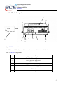
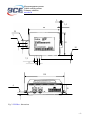
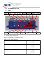
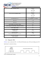
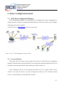
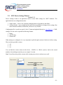
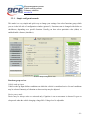
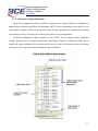
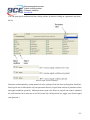
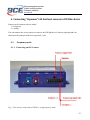
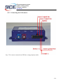
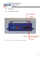
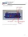
Fleet management systems Vehicle security systems Telemetry solutions www.bce.lt FM Blue/Blue+ User manual Version 1.1 Fleet management systems Vehicle security systems Telemetry solutions www.bce.lt Contents 1. FM Blue/Blue+ device information .............................................................................................. - 3 1.1. Safety and legal information .................................................................................................. - 3 1.2. Description ............................................................................................................................. - 3 1.3. Package ................................................................................................................................... - 3 1.4. Technical specifications ......................................................................................................... - 4 1.5. Physical properties ................................................................................................................. - 5 1.6. Pinout & diagnostic LEDs ...................................................................................................... - 7 1.6.1. Pinout .............................................................................................................................. - 7 1.6.2. Diagnostic LEDs ............................................................................................................. - 8 1.7. Installation .............................................................................................................................. - 9 1.8. Configuration........................................................................................................................ - 10 1.9. Support ................................................................................................................................. - 10 1.10. Document versions ........................................................................................................... - 10 2. Annex 1. Installation instructions ............................................................................................... - 11 3. Annex 2. Configuration manual .................................................................................................. - 16 3.1. BCE Device Configuration Manager ................................................................................... - 16 3.1.1. Users and Dealers.......................................................................................................... - 16 3.1.2. Devices and Retranslators ............................................................................................. - 17 3.1.3. Firmware ....................................................................................................................... - 17 3.1.4. GSM operator groups .................................................................................................... - 17 3.1.5. XML settings................................................................................................................. - 17 3.2. BCE Device Settings Wizard ............................................................................................... - 18 3.2.1. Simple configuration mode ........................................................................................... - 19 3.2.2. Advanced configuration mode ...................................................................................... - 21 3.2.3. Function signals ............................................................................................................ - 23 3.2.4. Functions ....................................................................................................................... - 24 4. Connecting “Vepamon” LLS fuel level sensors to FM Blue device .......................................... - 27 4.1. Frequency mode. .................................................................................................................. - 27 4.1.1. Connecting one LLS sensor. ......................................................................................... - 27 4.1.2. Connecting two LLS sensors. ....................................................................................... - 28 4.2. Analog mode ........................................................................................................................ - 29 4.2.1. Connecting one LLS sensor .......................................................................................... - 29 4.2.2. Connecting two LLS sensors ........................................................................................ - 30 - -2- Fleet management systems Vehicle security systems Telemetry solutions www.bce.lt 1. FM Blue/Blue+ device information 1.1. Safety and legal information Do not disassemble the device. May interfere operation of adjacent electronic devices. Device may be damaged by water and high humidity. Installed by qualified professionals only. Copyright © Baltic Car Equipment, Ltd. All rights reserved. Reproduction, transfer, distribution or storage of part or all of the contents in this document in any form without prior written permission of Baltic Car Equipment is strictly prohibited. 1.2. Description FM Blue+ is a device with GPS and GSM connectivity, designed for object tracking. It is able to acquire information on object location, speed, direction, etc. and transfer the data via GSM network. Digital and analog inputs of the device may be used to connect different external sensors/devices. Outputs of the device may be used to control external equipment remotely. FM Blue+ is able to read FMS CAN data (protocol J1939) from vehicles. Flexible configuration allows users/dealers to adjust the device to meet their specific requirements. 1.3. Package FM Blue+ is shipped to a customer in a cardboard box and contains all required components for operation*. Package contents: 1. FM Blue+ device (control unit) 2. External GPS antenna 3. External GSM antenna 4. Wires + 1A fuse -3- Fleet management systems Vehicle security systems Telemetry solutions www.bce.lt Note. SIM card is not included, but is necessary to operate the device. Contact your local GSM operator to purchase a SIM card. BCE recommends a M2M SIM card for best performance and reliability. 1.4. Technical specifications Table 1. FM Blue+ technical specifications GSM 850/900/1800/1900 MHz GSM/GPRS protocol stack 3 GPP Release 4 compliant Sensitivity: <-107 dBm @ 850 / 900 MHz <-106 dBm @ 1800 / 1900 MHz GPRS class 10 (up to 85.6 kbps), class B Jamming detection GPS U-blox Neo 6Q Precision: Position: 2.5m CEP Take off time: 1 second „hot start“ in the open air < 30 seconds warm start in the open air (average) 30 seconds cold start in the open air (average) Sensitivity: -148dBm cold start -162dBm tracking Accelerometer LIS33DE Flash IC 4Mb, SPANSION FL032P FM Blue+ Physical properties Dimensions (HxWxD): 26 x 80 x 55 mm Weight: approximately. 73 g Operating temperature range Operation / Storage: -40 Cº to +85 Cº Electrical properties Operation’s flow: Active Mode: at 12V - < 50mA Sleep Mode: at 12V - < 8mA 6 – 34V operating voltage, min 10V to start Protection from impulses up to 120V Power cut-off registration to the event log Interfaces 4 digital inputs 3 x ADC: 1 ADC: 0..16 V, 11 bit 2 x ADC: 0..36 V, 11 bit 2 digital outputs CAN data interface 1-WIRE RS-232 EIA485 -4- Fleet management systems Vehicle security systems Telemetry solutions www.bce.lt 1.5. Physical properties 7 9 1 1 TOP SIDE 5 8 3 6 4 2 2 Fig. 1. FM Blue+ front view. Note. To insert a SIM card, loosen device mounting screws at the bottom of the device. Table 1. FM Blue+ components No. 1 2 3 4 5 6 7 8 9 Short description Mounting screws place Device box mounting screws Device and GPS status LED GSM status LED GPS antenna socket (blue) GSM antenna socket (purple) IMEI and hardware ID sticker SIM card Socket 2x8 pins -5- Fleet management systems Vehicle security systems Telemetry solutions www.bce.lt 3 3,5 80 19 7 55 10 7,5 5 101 6 26 Fig. 2. FM Blue+ dimensions -6- Fleet management systems Vehicle security systems Telemetry solutions www.bce.lt 1.6. Pinout & diagnostic LEDs 1.6.1. Pinout EIA485 (A) Green RS23 (TX) Purple CAN LOW Orange EIA485 (B) Green/black RS232 (RX) Blue CAN HIGH Orange/black 1-Wire Yellow ADC5 Grey IN2/ADC4 Green/ black ADC3/OUT2 White IN3/OUT1 Purple/black IN4 Blue/black EXT BAT/ADC6 Brown BATTERY + Red IN5 Grey/black GROUND Black Fig. 3. FM Blue+ pinout and cable colors. Electrical properties of the device are shown in Table 2. Table 2. FM Blue+ electrical properties. ADC Power supply multiplier (adc2) 0.025V +-1.5% ADC 11bit ADC 3 multiplier (adc3) 0.01V +-1.5% ADC 11bit max 20V ADC4 multiplier (adc4) 0.0205V +-1.5% ADC 11bit max 40V -7- Fleet management systems Vehicle security systems Telemetry solutions www.bce.lt ADC5 multiplier (adc5) 0.0205V +-1.5% ADC 11bit max 40V ADC EXTBAT multiplier (adc6) 0.0205V +-1.5% ADC 11bit max 40V EXT BAT OUT (+) 13.5V regulated 1.5A limited OUT1 (-) 1.7A OUT2 (-) 1.7A Power supply, min start up voltage 10V Power supply, min operating voltage after start up 6V Power supply, stage1 30V Clamping voltage clamping type 34V varistor IN2,IN3,IN4,IN5 Max measuring frequency, accuracy 3Khz, +/-1Hz IN2, IN3, IN4, IN5 voltage threshold 4.7V, +/-3% 1.6.2. Diagnostic LEDs FM Blue+ has two indication LEDs – for GPS and GSM modem status. LEDs start flashing only if IN5 digital input is connected to battery +. Fig 4. LED flash signal. Example. -8- Fleet management systems Vehicle security systems Telemetry solutions www.bce.lt Table 3. Short flash meaning. GPS status. Short flashes count Meaning 1 No GPS signal 2 Poor precision. HDOP>1.5 3 3 satellites locked. HDOP<1.5 … ... 12 12 satellites locked. HDOP<1.5 Table 4. Long flash meaning. GSM modem status. Long flashes count Meaning 1 Modem connected to server, Modem connected to Internet, Modem GPRS registered, Modem GSM registered, Modem SIM card ok, Modem turned on 2 Modem connected to Internet, Modem GPRS registered, Modem GSM registered, Modem SIM card ok, Modem turned on 3 Modem GPRS registered, Modem GSM registered, Modem SIM card ok, Modem turned on 4 Modem GSM registered, Modem SIM card ok, Modem turned on 5 Modem SIM card ok, Modem turned on 6 Modem turned on 7 Device started 1.7. Installation FM Blue+ is installed where risk of mechanical damage, high humidity and extreme heat is low. Device is mounted stable to vehicle body, therefore ensuring correct operation of the internal accelerometer. Complete installation manual is available as Annex 1. -9- Fleet management systems Vehicle security systems Telemetry solutions www.bce.lt 1.8. Configuration FM Blue+ is meant to be operated through a configuration/retranslation server, where dealers/users can configure their devices to fulfill specific requirements. Configuration manual is available as Annex 2. 1.9. Support FM Blue+ is built to be a reliable, stable and easy to install device. Please read and follow provided installation and operating instructions carefully. However, if you encounter difficulties while installing or using this product, technical support is available and may be reached by e-mail [email protected]. 1.10. Document versions Table 5. Document versions Version Date 1.0 2012.03.20 1.1 2012.11.09 Changes Document created. Updated configuration description, added LLS connection - 10 - Fleet management systems Vehicle security systems Telemetry solutions www.bce.lt 2. Annex 1. Installation instructions List of suitable vehicles FM Blue+ is intended for all vehicles with petrol or diesel engines, where negative pole is body of the vehicle. Device must be connected to the vehicle battery, ensuring constant power supply even if the engine is not working and ignition is off. When active, FM Blue+ uses a small amount of direct current (DC) – less than 50 mA at 12V. It can be mounted in 12 V or 24 V vehicles. Standby mode This is a mode of the device when the vehicle ignition is turned off, and there are no active alarms. In this mode, the GPS receiver is switched off in the control unit (in order to reduce power consumption) and communication with the server intervals are increased. Device switches to active mode if programmed trigger is detected (for example accelerometer signal). Active mode This is a mode when ignition is on, or when any programmed trigger is active. In this mode, GPS receiver is enabled in the central unit and connection with the server is carried out more frequently. After ignition is switched off, the central unit remains active for another 10 minutes. Free configuration of data dispatch frequency is possible. During the data transfer (GSM / GPRS communications), short-term increase in current consumption of up to 100 mA is possible. Power-line (primary or back up battery) has to be connected via 1A fuses. Basic instructions before beginning the installation Quality of connections, location of the device and its’ antennas, etc. play a significant role on accurate operation of the system. Below are some tips and rules for correct installation to attain professional quality and ensure maximum efficiency of the device. Location for central unit installation Central unit should be hidden in a difficult to access location to prevent unwanted interference by unauthorized persons. Small size and flat body makes it easy to do and allows use of small gaps for installation. - 11 - Fleet management systems Vehicle security systems Telemetry solutions www.bce.lt The device must be fixed in the vehicle in position where connectors are oriented to the ground. This will prevent moisture condensation inside the unit. Electrical connections Control unit must be powered by continuous voltage. When starting the engine, voltage can not fall below 8 V. It is desirable that power supply for the device is connected to the factory cable led from battery terminals. This allows operation of the unit despite of failure of any vehicle fuses. Mechanical connections To highest possible extent, cavities in the vehicle should be used for wiring. If you need to make a new hole, it must be protected against corrosion appropriately! Wiring connection must be made by brazing, and not merely mechanical wire connection. It is especially important to protect the connections with insulation for high-resistance atmospheric conditions. Do not use insulation with unknown resistance parameters. Efforts should be made to tie the new wiring into the car's standard wiring bales. Installation of central unit Steps to install central unit: Insert a SIM card into the device; Install GSM and GPS antennas; Install central unit; Connect power supply; Connect array; Connect ignition wire to a digital input (usually IN5); Connect other devices (optional). SIM card SIM card must be inserted into the device before starting installation. The device must be turned off when inserting SIM card. Before inserting the SIM card, make sure you have activated GPRS connection, the card’s PIN code must be disabled. If the vehicle is travelling to foreign countries, roaming service must be activated for the SIM card. The SIM card and phone number must be checked and clearly marked on the installation certificate of the device. - 12 - Fleet management systems Vehicle security systems Telemetry solutions www.bce.lt IMPORTANT! Before inserting a SIM card, do not forget to disable PIN code. Otherwise, the device will not work, and the SIM card will be blocked. GPS antenna installation GPS antenna is the main element responsible for vehicle positioning accuracy and quality. To ensure best possible GPS signal reception and evaluating GPS signal character, there are strict requirements for correct installation of GPS antenna: The accordingly marked side of the antenna must be invariably directed to the sky (sticky side facing ground). The antenna must be oriented horizontally (not at an angle) and oriented with the corresponding side towards the top. The antenna should not be covered with metal sheet or reinforced glass. In vehicles with standard glass (e.g., without built-in heating elements), antennas can be mounted on panels or under its lining at the windscreen. The antenna must have open view to the sky, unimpeded with windowsills or other metallic elements. In vehicles where it is not possible to place the antenna under the windscreen (vertical windscreen, armored glass), the antenna can be installed in the vehicle’s bumper or in other element that ensures the free access to the sky. The installed antenna should be hidden and not visible. Fixing of the antenna must be stable and immobile, providing for the installation durability. It is necessary to take into account events, which may lead to loss of antenna’s stability, to select the mounting location and methods that would allow to avoid these factors. Antenna’s position changes are not permitted, because it may result in loss of appropriate antenna’s orientation. Cable to the GPS antenna must be as short as possible, and avoid areas with high electromagnetic interferences. Arbitrary lengthening or shortening of the cable is not allowed. The wire surplus should be twisted into a circle with a radius larger than 10 cm. The cable must not be bent, or twisted at tight angles. GPS antenna cable must not be laid in parallel to GSM antenna cable, also the two cables cannot be twisted together. GSM antenna installation GSM antenna is responsible for transfer of collected data and connection with central server. Good antenna’s performance is the key element in obtaining information from the device. - 13 - Fleet management systems Vehicle security systems Telemetry solutions www.bce.lt GSM antenna does not require orientation to open sky; however you should be aware that metal elements weaken the GSM signal. GSM antenna must be placed in the panel upholstery, or in a place which provides a good GSM signal reception (avoid excessive covering with metal sheet). GSM antenna must be installed in more than 40 cm away from the control unit, as well as from other electronic devices. It is also necessary to take into account the emission of the antenna’s high frequency radio waves, which may interfere with operation of electronic devices. In case antenna is difficult to place in the cabin (strong GSM signal suppression), it may be installed in any other element allowing the reception of the GSM signal. As for GPS antenna, GSM antenna should be hidden from outside observers. Device installation Central unit is only mounted in inside of the vehicle, it can not be installed in the engine chamber, next to the cabin, or in the area of exposure to direct external conditions. Central unit must be hidden (for example, under the upholstery), as well as protected from moisture exposure. Device must be fastened in a stable position to avoid random twitches and displacements (suspension on cables is strictly prohibited). Central unit must be mounted horizontally. Precise orientation is of particular importance to flawless operation of the system, since the device is equipped with acceleration sensors recording the data which directly affects the results obtained. Pinout and cable colors are shown in figure 1. EIA 485B green/black, 20 AWG EIA 485A, green, 20 AWG RS 232 RX, blue, 20 AWG RS 232 TX, purple, 20 AWG CAN H (+), orange/black, 26 AWG CAN L (-), orange, 26 AWG ADC5/OUT1, gray, 26 AWG ADC3, white, 26 AWG EXT BAT/ADC6, brown, 20 AWG 1-Wire, yellow, 26 AWG IN2, green/black, 26 AWG IN3, purple/black, 26 AWG BATTERY +, red, 20 AWG IN4, blue/black, 26 AWG GROUND, black, 20 AWG IN5, gray/black, 26 AWG Annex 1. Fig. 1. FM Blue+ pinout. Wire side. - 14 - Fleet management systems Vehicle security systems Telemetry solutions www.bce.lt Power supply Power supply of central unit has to be connected directly from the vehicle’s battery, using 1A fuse. IMPORTANT! Power supply may be connected to the central unit only after connecting GSM and GPS antennas! When disconnecting the device, you must first turn off the power supply, and only then disconnect the antennas! Ground wire Ground wire should be connected to the vehicle body. A reliable electrical contact with the body must be ensured, wire has to be bolted. Ignition input (combustion lock status) Connect a wire of the vehicle where voltage is present only when ignition is activated to IN5. Universal digital inputs (optional) Universal Digital inputs (IN2; IN3; IN4; IN5) are intended to collect data from remote devices. Analog inputs (optional) Analog inputs are intended to collect data from remote devices by measuring voltage. ADC3 range 0-20V; ADC4, ADC5, ADC6 range 0-40V. - 15 - Fleet management systems Vehicle security systems Telemetry solutions www.bce.lt 3. Annex 2. Configuration manual 3.1. BCE Device Configuration Manager BCE Configuration Manager is a web based service for adding new devices, changing device settings, firmware, operators, creating retranslations and more. This service allows you to configure and manage your devices remotely. You may access it at http://fmset.eu if you have an account. Annex 2. Fig. 1. Fleet management system scheme 3.1.1. Users and Dealers Each dealer has an account and can control all his devices via BCE Device Configuration Manager. If the dealer has a network of dealers, he can control the sub-dealers and their devices. Do not forget to select the parent dealer when creating new dealers and devices. After creating the devices you can change the dealer for one or a group of them. In the “Devices” tab select the devices you want to change the dealer for, click “Transfer selected devices”, select the dealer you need and click “Transfer”. - 16 - Fleet management systems Vehicle security systems Telemetry solutions www.bce.lt 3.1.2. Devices and Retranslators To create a new device, click on “New device”, select the hardware version, click “Next”, enter the IMEI number and the telephone number of the SIM card in your device. ICCID and IMSI will be read from the SIM card automatically. When creating a device, you can also change other settings – firmware, operator list, XML settings, dealer, server, APN, SMS numbers and custom values. You will be able to change them later. Retranslators can be used to connect the device to different networks using popular protocols. To create a new retranslator, click on a device in the “Devices” tab, go to “Retranslators”, select the protocol, enter the server IP address and port (f.e. 100.100.100.100:2222). You can duplicate a single device by creating several retranslators to different servers. 3.1.3. Firmware Firmware versions depend on hardware versions of the device. Firmware version marked K is used on hardware versions 4.0 and 4.1, L – 4.5, M – 5.0. The higher the number of the firmware – the newer it is. Firmware versions are created and uploaded by the BCE team. 3.1.4. GSM operator groups You can create and edit preferred operator lists. Each list belongs to a certain dealer, however, you can create several lists for a dealer and set different list of operators for each device. 3.1.5. XML settings XML settings may be uploaded to the device and used to tune it for the best performance and requirements of your system. You will find several prepared settings created by our team. However, you may use BCE Device Configuration Wizard to create settings that meet your specific needs. After the settings are ready just upload them to the devices. - 17 - Fleet management systems Vehicle security systems Telemetry solutions www.bce.lt 3.2. BCE Device Settings Wizard Version 1.3.3 Device settings wizard is an application used to create XML settings for “BCE” hardware. The application has two configuration modes: 1. Simple mode – easier to use, functions changing based on checkboxes and sliders. 2. Advanced mode – more complicated, but gives more possibilities to change device settings. Has more functions included, which make your device very flexible. Configuration file is saved in a special “dswiz” format and uploaded directly to www.fmset.eu → XML settings. File also can be exported in following formats: 1. Binary 2. ASCII binary 3. Wialon xml When settings are configured, it is very important to pick the right version of the device before saving. There are three possible versions: 1. 4.0 2. 4.5 3. 5.0 You can find the version written on the device – HW/ID, f.e. 1-51-01 (need to look at the second number), this marking means that you are using 5.0 version. Note. You will need to pick the version while creating a new device in fmset.eu as well. Picture1. Device version selection - 18 - Fleet management systems Vehicle security systems Telemetry solutions www.bce.lt 3.2.1. Simple configuration mode This mode is a very simple and quick way to change your settings. Just select functions group which you see in the left side of configuration window (picture2.). Functions state is changed with sliders or checkboxes, depending on a specific function. Usually you have select particular value (slider) or enable/disable a feature (checkbox). Picture2. Simple configuration mode Functions group review. Vehicle wake up input Vehicle wake up input defines conditions on which the vehicle is considered active. Several conditions may be selected. Intensity of vibration to detect activity may be adjusted. Device power mode Device may be always active or activated only if ignition is on or movement is detected. It goes to sleep mode when the vehicle charging voltage falls. Voltage level is adjustable. - 19 - Fleet management systems Vehicle security systems Telemetry solutions www.bce.lt Remote connection mode Remote connection defines how often the device connects to server. Usually it is always connected while in home country and connected on ignition when abroad. In that case, when the ignition is off, the device sends data packets periodically to save data traffic. GPS data fix mode GPS data fix mode allows you to configure the accuracy of vehicle track, the device records and minimum requirements for connection quality. The smaller the values in the “Course change” and “Speed change” fields, the more points are recorded and therefore more accurate track is displayed. However, this results in higher data traffic. GPS coordinate timeout is the maximum period between recorded points if the vehicle has not changed its course or speed enough to record a point. Minimum requirements for signal quality may be set by defining minimum number of satellites to be locked and maximum HDOP value. Floating size dataset The size of data messages recorded and sent by the device is variable. It may be changed by selecting more/less traced values. This may be configured separately for ignition on/off, home country and abroad. If you want to send messages with all values included, unselect “Use floating size dataset”. Digital inputs fix mode The values of sensors connected to the selected inputs will be recorded. Maximum period between records may be set. Counter/frequency mode The device can register the number or frequency of changes in sensor values (counter/frequency mode). Maximum period between records may be set. Operator list Operator list may be edited in “Device settings wizard”, as well as in “BCE device configuration manager (fmset.eu)”. - 20 - Fleet management systems Vehicle security systems Telemetry solutions www.bce.lt 3.2.2. Advanced configuration mode Most fleet management systems and GPS tracking devices on the market are configured by manufacturers with little possibilities for adjustment. “BCE” device configuration system allows you to create unique settings for different and specific needs in fleet management by dynamically changing most settings of device. We hope you will enjoy the results of your configurations. Advanced configuration mode designed to make “BCE’ device settings widely adjustable. Settings functions may be adjusted dynamically depending on internal, external and virtual device signals and signals conditions. Every logical item has its own value. One function can have more than one logical item. Logical item values depend on signal conditions. Picture3. Functions and logical items - 21 - Fleet management systems Vehicle security systems Telemetry solutions www.bce.lt You can open signal condition and value editing window by double clicking on a parameter item from the list. Picture4. Signal value and conditions Functions are determined by setting numerical value, picking it from the list or picking from check box. Each logical item is dedicated to only one particular function. Logical item consists of parameter values and signal conditions (picture4.). Maximum items count is 84. However, logical unit count is unlimited for each function, but it must not exceed 84 in total. By clicking check box toggle your desired signal state (picture4.). - 22 - Fleet management systems Vehicle security systems Telemetry solutions www.bce.lt 3.2.3. Function signals Signal name Reset Modem on IN1 – motion IN6 Reserved System time registered Reserved Poor GPS signal GSM jamming Roaming GSM registered GPRS registered Internet active Preferred operator active GPS speed present SIM card ok IN2 IN3 IN4 IN5 IN7 – engine on IN8 One hour tick Six hour tick Stack size threshold reached Voice call Data call Static signal1 Static signal2 Timer1 IbuttonPresent Reserved Signal description Turn on temporarily after the system is restarted to indicate the event Modem of the device is enabled Virtual input, used for motion detection Virtual programmable input Reserved for future The device has turned UTC time internally from GPS or internet Reserved for future GPS signal does not meet the minimum requirements according to “F_GpsQualityMaxHdop” and “F_GpsQualityMinSat” GSM/DCS jammer is detected and it is disturbing normal use of GSM/DCS service Device is registered to a roaming network Device is registered to any network Device is registered to GPRS data services Device is connected to internet Device is registered to an operator from the preferred list GPS speed detection over 10km/h SIM card is inserted and PIN code removed Physical – digital input Physical – digital input Physical – digital input Physical – digital input Virtual input, battery charging detected Virtual programmable input Every hour for 10 minutes period Every six hours for 10 minutes period There is more data in stack than allowed Voice call detected, settings locked for 30 minutes Data call detected, settings locked for 30 minutes General first static signal General second static signal Special structure for internal timer signal “Dallas key” detected Special structure for internal timer signal Table1. Signal descriptions - 23 - Fleet management systems Vehicle security systems Telemetry solutions www.bce.lt 3.2.4. Functions Functions name 1.1 F_ModemPower 1.2 F_GpsPower 2.1 F_InternetConnection 2.2 F_ServerConnection 2.3 F_DataSendPeriod 2.4 F_DataSendOnInputsChange 2.5 F_BroadcastMessagesPeriod 3.1 F_GpsQualityMaxHdop 3.2 F_GpsQualityMinSat 3.3 F_GpsReadPeriod 3.4 F_MaxTimeBetweenTwoGpsPoints 3.5 F_GpsCourseChangeFix 3.6 F_GpsSpeedChangeFix 3.7 F_InputsChangeFix 4.1 F_Dataset7_Mask1 4.2 F_Dataset7_Mask2 4.3 F_Dataset7_Mask3 5.1 F_GeneralBitConfig 5.2 F_VibrationThreshold Description/value expression GSM modem power mode (on/off) GPS device power mode (on/sleep) Create new internet connection (PDP context*), [permit/ban] Controls connection to server (connect/disconnect after 10 minutes) Period in which data is sent to server (automatic/custom) Mask of inputs which may generate data transmission without waiting period timeout (tick a check-box to select desired input) Reserved. Will be able in near future Maximum HDOP* of position to accept it to read (Recommended value – 35) Minimum satellites count for acceptance to read it Period in which coordinates are read from GPS and put to internal track filter (never/value=seconds) Maximum time between two fixed points (never/value=seconds) Minimum course change for device to fixate it (value expressed in degrees) Fixation of vehicles speed difference from the last set value (expressed in km/h) Registers change of selected input state (tick a check-box to select desired input) Selected data will be included into the data packet (see annex 1) Selected FMS-CAN (J1939)* data will be included into the data packet (see annex 2) Selected data will be included into the data packet (see annex 3) General bit configuration (tick a check-box to select desired function) Vibration (IN1) threshold (if value > selected threshold, IN1-motion=1). Used for detecting motion, recommended value 200 - 24 - Fleet management systems Vehicle security systems Telemetry solutions www.bce.lt 5.3 F_NotDeliveredDataThreshold 5.4 F_In8VoltageThreshold 5.5 F_In6VoltageThreshold 5.6 F_FrequencyCounterSelect 5.7 F_CanFunctionSelect 5.8 F_EIA485FunctionSelect 5.9 F_RS232FunctionSelect 5.a F_NewConectionsToInternetLimiter 5.b F_Timer1 5.c F_Timer1_GMT 5.d F_Timer2_Control 5.e F_Timer2_Threshold 5.f F_OUT1_Control 5.g F_OUT2_Control 6.1 F_Dataset1_Timeout 6.2 F_Dataset2_Timeout 6.3 F_Dataset3_Timeout 6.4 F_Dataset4_Timeout 6.5 F_Dataset51_Timeout 6.6 F_Dataset8_Timeout 6.7 F_Sms_TrigerMaskRising 6.8 F_Sms_TrigerMask_Faling Stack size threshold to generate signal “Stack size threshold reached”. Value expressed in bytes. Power supply voltage threshold. Expressed in volts (if value > threshold, IN8=1) ADC3 voltage threshold. Expressed in volts (if value > threshold, IN6=1) Input mask for counter – frequency mode (tick a check-box to select desired input mode). Used for sensors, to work in counter or frequency mode Selects CAN function. Enables CAN bus reading. Possible values: J1939-FMS; J1939 OBDII*; FMS ACK; FMS request; RS485* function select. Enables RS485 input reading. Used for LLS*sensors and J1708* Reserved. Will be able in near future. Limits next possible connection to internet (value expressed in seconds) Special structure for internal timer signal Used to set GMT value. Special structure for internal timer signal Time threshold expressed in seconds. Used with 5.d function Function for OUT1 output control. Works in three modes: off1 – output disabled, but can be controlled with GPRS commands; on (minus) – enabled; off2 – disabled; Function for OUT2 output control. Works in three modes: off1 – output disabled, but can be controlled with GPRS commands; on (minus) – enabled; off2 – disabled; Not used for wialon Not used for wialon Not used for wialon Not used for wialon Not used for wialon Not used for wialon Sms mask value. Sending sms when changing from 0 to 1 (tick a check-box to select desired input) Sms mask value. Sending sms when - 25 - Fleet management systems Vehicle security systems Telemetry solutions www.bce.lt 6.9 F_Sms_NextSmsTimeout 6.a F_Sms_MaxSmsPerHour Reserved_43…..Reserved_63 changing from 1 to 0 (tick a check-box to select desired input) Next sms timeout. Expressed in seconds Maximum sms per hour Reserved for future Table2. Function descriptions HDOP – horizontal dilution of precision. This gives an indication of precision of the position fix from GPS, based on the satellites it is currently using and its geometry. PDP context – packet data protocol context is a term used in the mobile wireless network indicating a logical association between an MS (mobile station) and PDN (Public data network) running across a GPRS network. The context defines aspects such as routing, qos (quality of service), security, billing etc. FMS-CAN (J1939) – “fleet management systems” interface is a standard interface to vehicle data of commercial vehicles. J1939 is a vehicle bus standard used for communication and diagnostics among vehicle components. OBD-II – on board diagnostics, is an automotive term, referring to a vehicles selfdiagnostic and reporting capability. The OBD-II standard specifies the type of diagnostic connector and its pinout, the electrical signaling protocols available, and the messaging format. EIA-485, also known as TIA/EIA-485 or RS-485, is a standard defining the electrical characteristics of drivers and receivers for use in balanced digital multipoint systems. J1708 - standard used for serial communications between ECU (Electronic control unit) on a heavy duty vehicle and also between a computer and a vehicle. LLS – Liquid level sensor - 26 - Fleet management systems Vehicle security systems Telemetry solutions www.bce.lt 4. Connecting “Vepamon” LLS fuel level sensors to FM Blue device Sensors can be connected in two modes: 1) Frequency 2) Analog You can connect one or two sensors at a time to one FM light device. Sensors signal ground wire connects to the same pin with devices ground (-) wire. 4.1. Frequency mode. 4.1.1. Connecting one LLS sensor. Fig. 1. One sensors connection to FM blue+ using frequency mode. - 27 - Fleet management systems Vehicle security systems Telemetry solutions www.bce.lt 4.1.2. Connecting two LLS sensors. Fig. 2. Two sensors connection to FM blue+ using frequency mode. - 28 - Fleet management systems Vehicle security systems Telemetry solutions www.bce.lt 4.2. Analog mode 4.2.1. Connecting one LLS sensor Fig. 3. One sensors connection to FM blue+ using analog mode. - 29 - Fleet management systems Vehicle security systems Telemetry solutions www.bce.lt 4.2.2. Connecting two LLS sensors Fig. 4. Two sensors connection to FM blue+ using analog mode. - 30 -