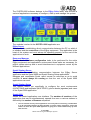
1
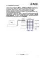
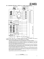
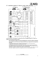
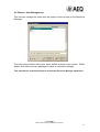
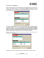
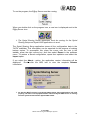
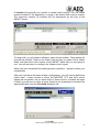
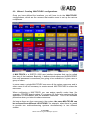
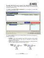
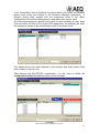
INSTALLATION
CONFIGURATION AND ADMINISTRATION.
MANUAL
ED. 12/04
E@sy Server 1.61.004 or higher
Resource Manager 1.61.001 or higher
Systel 6000 3.00.003 or higher
Systel 6000
Multiconferencing and Multiplex System.
INDEX:
1.- Introduction.
2.-System installation.
2.1.- Hardware and Software Requirements.
2.2.- Hardware Installation.
2.3.- Software Installation.
2.4.- Example: 20 lines in 1 studio.
2.5.- Example: 12 lines in 3 studios.
2.6.- Example: 14 lines in 1 studio and production room.
2.7.- Example: 12 lines in a main studio and sends.
3.- EASY SERVER application.
4.- RESOURCE MANAGER Application.
4.1.- Wizard. Available Devices.
4.2.- Wizard. Matrix Circuits.
4.3.- Wizard. Matrix-CODEC Connections.
4.4.- Wizard. CODEC Phone Book Management.
4.5.- Wizard. User Management.
4.6.- Resource management.
5.- SYSTEL SHARING SERVER Application.
6.- SYSTEL SHARING SETUP Application.
6.1.- Wizard. Creating a location.
6.2.- Wizard. Creating ‘MULTIPLEX’ configurations.
6.3.- Wizard. User Group Management.
6.4.- Wizard. User Management.
7.- SYSTEL 6000 Application.
8.- Maintenance. Software Upgrading.
9.- Troubleshooting quick guide.
WARRANTY FOR AEQ SOFTWARE PRODUCTS
Systel 6000
Multiconferencing and Multiplex System
2
1.- Introduction.
The Systel 6000 software allows to establish a MULTICONFERENCING system with up to 20
simultaneous lines through the transparent control of EAGLE or COURSE ISDN audiocodecs or
permanent connection (analog hybrids, 4w connections with other studios,...) performing
automatically the required cross-points in the IMPACT-CADDY matrix.
The application controls the AEQ E@sy devices in real time, performing the functions of a
Multiconferencing and Multiplex System:
Allows phone calls to be generated or received and integrated in multiconferencing
groups with other phone lines and 4-wire audio lines from the studio or remote ones.
Each Systel 6000 multiconferencing group, called ‘Multiplex’, creates a ‘N-1’ lines
group to send each line mixed audio from the entire group, called ‘Master’, except its
own.
Each participant in the Multiplex can be set in one of these states:
o ON AIR - Receives and contributes to the group (Master).
o INTERCOM - speaking exclusively with the operator or presenter.
o WAIT - only receives from the group.
o PFL - its audio is sent to a listening circuit.
o AUX - its audio is sent to an auxiliary program.
The AUX circuit can be used as a secondary Master signal, creating two busses for the
program. In addition, it can be used to send one or more lines to a recoding bus. It is
possible to create up to 8 auxiliary circuits and to define its operation, as 2 wires or 4
wires.
It is possible to create up to 8 intercommunication circuits in order to speak with one,
some or all the lines.
BENEFITS AND SPECIAL FEATURES
• Allows multiconferencing, intercom, cueing and on-air functions to be created, with
circuits from phone lines, ISDN links or physical audio lines, microphone or internal,
digital or analog.
• Scalable, both in number and type of circuits and in number of controls.
• Incorporates and expands the functionality of the old AEQ Systel 3000 system, and
makes it more flexible.
• Incorporates and expands the functionality of the old 4-wire analog multiplex consoles,
typical of sports broadcasts from multiple locations and commentators, and makes it
more flexible.
• Input and output gain control for each line.
• Multi-user and multitasking.
• Possibility of centralizing all codecs in central control room.
Systel 6000
Multiconferencing and Multiplex System
3
The SYSTEL6000 software belongs to the E@sy Suite family and includes a
series of applications necessary to configure, start up and manage the system:
The modules involved in the SYSTEL 6000 application are:
E@sy Server
Responsible for establishing direct communication between the PC on which it
is installed and the control bus of the E@sy equipment. This application is the
heart of the system and must always be operating properly for the rest of the
applications to work.
Resource Manager
Enables basic hardware configuration tasks to be performed for the entire
E@sy equipment and applications environment; these tasks are necessary for
proper system start-up and to avoid interferences in equipment control by the
different applications.
Systel Sharing Server
Responsible for establishing communication between the E@sy Server
application and the Systel 6000 and Systel Sharing Setup applications.
Manages and coordinates Systel users’ access to resources so as to avoid
conflicts. It must always be running so that the rest of the Systel 6000
applications can work.
Systel Sharing Setup
This feature allows you specifically to configure the work environments
(LOCATIONS) and templates (MULTIPLEX), phone books (agendas) and users
of the Systel 6000 application.
Systel 6000
Shows the control application user interface. The number of sessions of the
application that can be simultaneously opened from one or various stations is
defined by the number of licenses requested.
You can execute as many client applications in as many PCs as necessary, provided there
is an IP connection between the PCs. Normally, a license will be required for each of the
stations in which the Systel 6000 application is going to be used simultaneously by more
than one user.
Systel 6000
Multiconferencing and Multiplex System
4
2. System installation.
2.1.- Hardware and Software Requirements.
MATRIX:
A matrix of at least 24x24 mono circuits is required. This matrix is made up of a
CADDY AD/DA converter and the IMPACT AES/EBU matrix.
Depending on the size of the system to be installed, this matrix may be
expanded to the following configurations:
48x48
72x72
96x96
120x120
While the Systel 6000 system will normally use only the IMPACT matrix,
you can dedicate part of a matrix to the Systel 6000 application and
another part to other E@sy applications—for example, to route other
audio signals inside your location by means of the IMPACT PLUS or
CODEC SHARE applications.
The standard matrix control application, IMPACT RealTimeControl, can
also be used simultaneously and will reflect the connections made by
Systel 6000, but the operator must avoid interfering with the connections
made by the Systel 6000 system.
The AES/EBU signals with which the IMPACT matrix works are stereo (12
circuits). This is why the CADDY converter must be used to separate the
24 audio circuits.
All the matrix lines that are dedicated to the Systel 6000 must be treated
as 4-wire lines, that is, input 1 corresponds to output 1, etc.
AUDIOCODECS:
The application achieves its maximum functionality when E@sy audiocodecs
with management such as the EAGLE and the COURSE are used. A complete
COURSE (10 boards) provides 20 channels at 64 kbps for 20 ISDN calls
occupying 3u.
If you already have EAGLE equipment, you can use it in a System 6000 system.
If you prefer to install just a few lines initially, but are considering the possibility
of expanding the system in the future, we recommend installing a COURSE.
DIRECT CONNECTIONS:
You can set up direct 4-wire connections without dialing management. They can
be used to connect other sources that will be able to take part in the
multiconference, for example, an analog hybrid, a connection with a studio for
interviews, etc.
Each MULTIPLEX session is limited to displaying a maximum of 20 lines on
screen, to include audiocodec and direct connections. However, you can conduct
multiple 20-line sessions by using the MASTERS as subgroups and multiplexing
the subgroups in external devices—for example, AEQ BC2533 console modules,
o even in free matrix connections.
Systel 6000
Multiconferencing and Multiplex System
5
Computer system connection and requirements
The system operates on an IBM-compatible PC running the Windows NT
(Workstation or Server) or 2000 (Professional or Server) operating system. The
minimum requirements are those specified in order for these operating systems
to work.
The computer on which the E@sy server application is installed must have a
serial (COM) port to connect the E@sy bus.
The computer where the Systel Sharing Server application is installed (it may
be the same one on which the E@sy server is installed, or a different one) must
have a parallel or serial or USB port to connect the hardlock that will be given
to you along with the applications. You will find more information about this
hardlock in Chapter 5.
The system can work on a network or a stand-alone workstation.
A minimum monitor resolution of 800x600 is required for the management
applications (E@sy Suite, Systel Sharing Server, Systel Sharing Setup) and a
minimum resolution of 1024x768 is needed for the control applications (Systel
6000, IMPACT Real Time Control).
Remote control applications (Systel 6000 and others) may be run on the same
computer where the E@sy server is installed, the same one where the Systel
Sharing Server is, or on different or additional workstations. These computers
must run the aforementioned operating systems, and an IP connection is
required between all the computers through a network. See the annex on IP
connections.
The E@sy suite applications require the operating system to have the TCP/IP
extension installed. This extension is automatically installed when a network card or a
modem is connected. If control is performed through a stand-alone computer with no
type of network connection, it will be necessary to install the generic “MSLoopback”
driver that is on the installation disks of both operating systems.
The hardware key requires a driver to make it functional. This entails installing the
HARDLOCK driver that is provided on the installation CD. This driver must be installed
even when you only want to execute these applications in demo mode. If you already
have the AEQ MAR4WIN automation system installed on that PC, you need not install
this driver.
The maximum number of concurrent users in the system will be defined by the
hardware key supplied, which must be installed in the PC where the System Sharing
Server is resident.
Systel 6000
Multiconferencing and Multiplex System
6
2.2.- HARDWARE installation.
You will need to connect the IMPACT, COURSE and EAGLE equipment items
to the PC in which E@sy Server is installed, through the E@sy control bus. For
this purpose, use the RS232 – RS422 converter supplied, which can be
external or internal in the IMPACT or EAGLE equipment. The CADDY
equipment items do not need to be connected to the control bus because they
do not require remote management.
If the converter is internal, the IMPACT, EAGLE or COURSE that performs the
interconnection function must be connected to the PC through an RS-232
series connection. The rest of the E@sy equipment items are connected to
this equipment through the RS-422 port, E@sy bus.
Systel 6000
Multiconferencing and Multiplex System
7
2.3.- Software Installation.
It is important to know where the different applications sould be installed.
The management applications (Systel Sharing Setup) will be installed in the
management center, and the Systel 6000 client applications may be installed
on any of the stations on the computer network.
The following diagram shows, in a didactic manner, the distribution of the
different applications at a radio station that has all the components of the E@sy
system, as well as the MAR4WIN management software. All audio circuits are
routed towards the IMPACT matrix, either directly, if they are digital signals, or
through the CADDY converter.
The computer network may be shared by the MAR4SUITE and EASY SUITE
applications; however, it is recommended that a station on the network be
dedicated to the EASY SUITE system’s server applications.
This PC must be constantly running and the equipment will be connected to it
through the E@sy bus and the hardlock. The E@sy Server and Systel
Sharing Server applications will run on it.
CONTROL ROOM
PC
CADDY
©
IMPACT
©
ON AIR STUDIO
EAGLE
©
PC
AUDIO
- EASY SERVER
- SYSTEL SHARING SERVER
- HARDLOCK
MIXER
COURSE
©
SERVER
ETHERNET
E@SY BUS
- SYSTEL 6000
SWITCH
-MAR4WIN
RECORDING STUDIO
AUDIO MAR4
PC
AUDIO
MIXER
MANAGEMENT
PC
- SYSTEL 6000
-MAR4WIN
- RESOURCE MANAGER
- SYSTEL SHARING SETUP
+ MAR4SETUP (optional)
Systel 6000
Multiconferencing and Multiplex System
8
To install the applications, start by inserting the E@sy Suite CD in the CD-ROM
drive and wait for the menu to be displayed on screen.
Select the preferred language by pressing ‘ENTER’:
Systel 6000
Multiconferencing and Multiplex System
9
Select ‘SYSTEL 6000’:
From this screen you can install the different applications one by one.
Systel 6000
Multiconferencing and Multiplex System
10
When you install the E@sy Server application, you will be asked to choose
between installing it as a service or as an application.
When E@sy Server is installed as an application, it works the same as any
other program in the sense that it is started and stopped manually by the user.
We recommend that most users install it as an application.
When E@sy Server is installed as a service, it operates in a different way.
E@sy Server starts automatically during system start-up and appears in the
taskbar. Because the user does not need to start or stop the program, the
E@sy Server icon does not appear on the desktop and it is not possible to stop
it by using the right mouse key. The service will remain active even if the
Windows session is closed.
NOTES:
Only a user with administrator’s rights over the equipment may install the
software in a PC connected to an intranet. Therefore, in this situation you may
need to contact your systems administrator.
If you wish to establish Windows security policies, you will have to change the
installation directory to, for example, “C:\AEQ\.”
Systel 6000
Multiconferencing and Multiplex System
11
When you install the Systel 6000 application, you will be asked to select which
of the three modules you prefer to install:
By default, all three applications are installed (stand-alone station). Deselect the
applications you do not wish to install (multistation).
Make sure that the HARDLOCK DRIVER is installed in the same station where
SYSTEL Sharing Setup is installed, and be sure that the key is plugged into that
station.
It is important to plan where the various applications are going to be
installed. The following diagram offers a didactic example of the distribution of
the different applications in a fictitious broadcasting station that has all the
components of the E@sy system integrated with the MAR4WIN management
software.
All the audio circuits are routed toward the IMPACT matrix through the CADDY
converter.
Although the computer network may be shared by the AEQ, MAR4SUITE and
E@sy SUITE applications, we recommend dedicating a network station to the
EASY SUITE system server applications. That dedicated PC should be
operating continuously; further, the equipment items must be connected to it
through the E@sy bus and the hardware key. The E@sy Server and Systel
Sharing Server applications will run in this same computer.
Systel 6000
Multiconferencing and Multiplex System
12
2.4.- Installation example: 20 lines in 1 studio.
CONTROL
NETWORK
E@SY SERVER
SYSTEL SERVER
HARDLOCK
E@SY BUS
COURSE
POTS
ISDN
ISDN
SWING
DIG.
DIG.
1
1
2
1
2
1/2
1/2
2
3
4
3
4
3/4
3/4
3
5
6
5
6
5/6
5/6
4
7
8
7
8
7/8
7/8
5
9
10
9
10
9/10
9/10
6
11
12
11
12
11/12
11/12
7
13
14
13
14
13/14
13/14
8
15
16
15
16
15/16
15/16
9
17
18
17
18
17/18
17/18
10
19
20
19
20
19/20
19/20
21/22
21/22
23/24
23/24
MASTER
BC-2533
21
BC-2500 CONSOLE
INTERCOM
BC-2578
22
MAR4WIN
SYSTEL CLIENT
AUX
PFL
SPEAKER
IMPACT
ANA.
AUDIOCODEC
EAGLE
CADDY
ANA.
PFL
23
24
MAIN STUDIO
CENTRAL CONTROL ROOM
IP
This example shows a SYSTEL 6000 system configured to obtain a 20-line
conferencing system in a single studio:
- The COURSE, in its complete configuration (10 boards) is connected to 10 ISDN lines and will
handle digital calls from other CODECs or conventional telephone calls through the G711
protocol. This enables the system to accept calls from listeners or journalists equipped with basic
or cellular telephones, and also two-way ISDN links with other radio stations or portable coders,
up to a total of 20 possible connections.
- The COURSE multicodec’s 20 analog audio inputs and outputs are connected to the CADDY
converter, which delivers them in digital form to the IMPACT digital matrix’s 10 AES/EBU inputs
and outputs.
- The 3 inputs and 4 outputs assigned to Master, Intercom, Aux and PFL must pass through the
CADDY to be separated and converted to analog signal. These signals can be conveyed, for
example, to a BC2500 mixing console. The MASTER signal and its return (mono) are connected
to a BC2533 telephone insertion module. In the console this is mixed with the rest of the program
signals.
- Any of the multiconference lines can be in contact with the program producer through the
intercom circuit.
- A line (or group of lines) can be assigned to the two-way ON AIR or AUXILIARY circuits, or to
the one-way PFL circuit.
- A ‘MAIN STUDIO’ location and a template with 20 codec lines will be configured.
A minimum of one user license will be required.
Systel 6000
Multiconferencing and Multiplex System
13
2.5.- Installation example: 12 lines shared by 3 studios.
CONTROL
NETWORK
E@SY SERVER
SYSTEL SERVER
HARDLOCK
E@SY BUS
IP
COURSE
POTS
ISDN
DIG.
DIG.
1
1
2
1
2
1/2
1/2
2
3
4
3
4
3/4
3/4
5/6
5/6
3
5
6
5
6
7/8
7/8
4
7
8
7
8
EAGLE
5
9
10
9
10
SWING
6
11
12
11
12
MAR4WIN 1
SYSTEL CLIENT 1
BC-2500
BC-2533
BC-2578
MASTER 1
INTERCOM 1
AUX 1
PFL 1
PFL
SPEAKER
IMPACT
ANA.
ISDN
AUDIOCODEC
CADDY
ANA.
13
14
9/10
9/10
11/12
11/12
13/14
13/14
15/16
15/16
17/18
17/18
19/20
19/20
21/22
21/22
23/24
23/24
15
16
MAR4WIN 2
SYSTEL CLIENT 2
BC-2500
BC-2533
BC-2578
MASTER 2
INTERCOM 2
AUX 2
PFL 2
PFL
SPEAKER
17
18
19
20
STUDIO 2
MAR4WIN 3
SYSTEL CLIENT 3
BC-2500
BC-2533
BC-2578
MASTER 3
INTERCOM 3
AUX 3
PFL 3
PFL
SPEAKER
21
22
23
24
CENTRAL CONTROL ROOM
STUDIO 1
STUDIO 3
In this example, the system is composed of 6 COURSE boards (12 calls) and a
simple 24x24 matrix.
Three locations are defined:
‘STUDIO 1’ with its MASTER 1, AUX 1, INTERCOM 1 and PFL 1 lines
‘STUDIO 2’ with its MASTER 2, AUX 2, INTERCOM 2 and PFL 2 lines
‘STUDIO 3’ with its MASTER 3, AUX 3, INTERCOM 3 and PFL 3 lines
Any of the three studios may have its own multiconferencing system.
A MULTIPLEX will be defined with 12 lines. When any studio opens this template, the other two
studios will not be able to use the CODEC lines.
A MULTIPLEX will be defined with 6 lines. In this case, two studios can simultaneously open two
independent multiconferences without interfering with each other.
A MULTIPLEX will be defined with 4 lines. In this case, each studio can work simultaneously with
four CODEC lines without interfering with each other.
The selection of MULTIPLEX templates is dynamic; that is, you can assign all your resources (in
this case, 12 CODEC lines) to a studio to set up a sports broadcast from multiple locations and
commentators and, when the sportscast is over, go back to a four-line template so that all the
studios can set up smaller conferences.
To be able to work simultaneously in three studios, at least three licenses will be required.
Systel 6000
Multiconferencing and Multiplex System
14
2.6.- Installation Example: 14 lines for 1 studio and production.
CONTROL
NETWORK
E@SY SERVER
SYSTEL SERVER
HARDLOCK
E@SY BUS
IP
COURSE
POTS
ISDN
ISDN
CADDY
ANA.
ANA.
1
1
2
DIG.
1
2
1/2
1/2
2
3
4
3
4
3/4
3/4
3
5
6
5
6
5/6
5/6
7/8
7/8
4
7
8
7
8
5
9
10
9
10
AUDIOCODEC
EAGLE
6
11
12
11
12
SWING
7
13
14
13
14
MAIN STUDIO
MAR4WIN
SYSTEL CLIENT
BC-2500
MASTER
BC-2533
15
AUX
16
PFL
PFL
SPEAKER
IMPACT
DIG.
9/10
9/10
11/12
11/12
13/14
13/14
15/16
15/16
17/18
17/18
19/20
19/20
21/22
21/22
23/24
23/24
17
INTERCOM 1
AA-01
18
INTERCOM 2
AA-01
19
INTERCOM 3
AA-01
20
INTERCOM 4
AA-01
21
INTERCOM 5
AA-01
22
INTERVIEW STUDIO
BC-2500
4 WIRE DIRECT CONNECTION
23
CENTRAL CONTROL ROOM
PRODUCTION
REMOTE STUDIO
EAGLE
128 KBPS LINK
AEQ LD-2
EAGLE
24
In this case, there are 7 COURSE boards providing 14 CODEC lines and a
simple 24x24 matrix made up of one IMPACT one CADDY.
There is a single MAIN STUDIO location in which MASTER, AUX and PFL are defined.
Additionally, five INTERCOM lines are defined (assigned to that location) that will be used from
the PRODUCTION room and will enable five producers to communicate with any of the
multiconference participants. By using 4W/2W converters such as the AEQ AA-01, they will be
able to use standard telephone terminals as intercoms.
The system in this example also has two direct connections to the matrix, one of which goes to a
local INTERVIEW STUDIO, and the other to a remote studio located in another city. The remote
studio is linked through a 128-kbps digital leased line, and two EAGLES are used to establish the
audio channel using low-delay AEQ LD-2 mono coding.
A single MULTIPLEX template will be defined, in which the 14 CODEC lines and the two
continuous connections will be set up. In this way, the people invited to the INTERVIEW STUDIO
and those invited to the remote studio will participate in the multiconference in the same way as
with the connections through the COURSE.
All the application users will share the same MULTIPLEX template. As many licenses will be
required as there are users who can access simultaneously.
Systel 6000
Multiconferencing and Multiplex System
15
2.7.- Installation example: 12 lines for a main studio and sends.
CONTROL
NETWORK
E@SY SERVER
SYSTEL SERVER
HARDLOCK
E@SY BUS
COURSE
CADDY
IMPACT
ANA.
ANA.
DIG.
DIG.
1
1
2
1
2
1/2
1/2
2
3
4
3
4
3/4
3/4
5/6
5/6
3
5
6
5
6
7/8
7/8
AUDIOCODEC
4
7
8
7
8
9/10
9/10
EAGLE
9
10
9
10
11/12
11/12
5
13/14
13/14
SWING
6
11
12
11
12
15/16
15/16
17/18
17/18
19/20
19/20
21/22
21/22
23/24
23/24
POTS
ISDN
POTS
ISDN
ISDN
MPAC-02
13
14
TH02ExMkII
MAR4WIN
SYSTEL CLIENT
BC-2500
15
16
EAGLE
MASTER
BC-2533
PFL
17
18
MAIN STUDIO
4W TO STUDIO 2
STUDIO 2
4W TO STUDIO 3
19
20
STUDIO 3
4W TO STUDIO 4
STUDIO 4
4W TO STUDIO 5
21
22
STUDIO 5
4W TO CCR
AUX
23
CENTRAL CONTROL ROOM
IP
24
In this example, the system is composed of six COURSE boards (12 calls via
IDSN) and a simple 24x24 matrix.
Also connected to the matrix are one AEQ TH02ExMkII (direct connection) hybrid for analog lines
and one EAGLE. If the EAGLE is connected to the E@sy bus, it can be controlled from the Systel
6000 application, which means that two additional call circuits are added to the 12 provided by the
COURSE.
A single MAIN STUDIO location is defined in which MASTER, PFL and 5 Intercoms are
configured and connected to four studios and to the CCR.
A single MULTIPLEX template is defined with all the CODEC lines and the direct connection to
the TH02ExMkII hybrid. From Central Control, all the communications will be managed and sent
to MASTER or to the secondary studios through the 4W INTERCOMS.
Although the multiplex is controlled in the central control (one license), in each studio there can be
a terminal to display the status of the multiplex (one license for each additional session).
Systel 6000
Multiconferencing and Multiplex System
16
3. EASY SERVER application.
If the E@sy Server application was installed as an application (as opposed to a
service), the relevant icon will be displayed on the desktop. Double-click the
icon to start the application. If it was installed as a service, the icon will
automatically appear in the taskbar.
Right clicking on this icon displays the ‘SHOW’ option, which lets you see the
program window:
In the application menu, select Setup / Port and in the
Communications section, configure the PC’s COM
port to be used with the following parameters: baud
rate: 38,400 bauds; data bits: 8; stop bits: 1; no
parity bit.
Each E@sy equipment has a node number that
identifies it when it is on a E@sy network. In the
Range section, configure between what numbers the
equipment search is desired. It is advisable to set this
range at the minimum possible (for example, from 0
to 6) to optimize speed.
Warning: the software will not detect equipment
items whose node number does not fall within this
range.
Systel 6000
Multiconferencing and Multiplex System
17
Once this range has been adjusted, the LEDs that indicate communication will
remain green when there is communication with any of the units:
The E@sy Server has two operating modes. If nothing has yet been configured
through the Resource Manager, it looks for units connected at the bus and
shows them on the screen. If certain units are configured, it will show them on
the screen and will cross out those units it cannot find with a red “X.”
It is important to make sure that all units are active before continuing the
process. If this is not the case, it is possible that one might be turned off, that
the cable is damaged or that the node number is not configured correctly.
Check the respective manual for each unit. It is advisable to remember that
IMPACT blocks connected to each other will be displayed as a single unit for
the software’s purposes.
In this example, there is an ‘EAGLE’ unit connected to the server PC, identified
by node 006 (from this moment onwards, it can be remotely controlled), and a
Course and an Impact that have been defined but that do not have a connection
with the system, either because they are not turned on, are not connected to the
bus, or because their node numbers do not match the configured ones.
This server program remains resident while E@sy equipment is being
controlled.
In the File menu, you have the option to search for the equipment again with the
Update option, and to close the program window using the Close option.
E@sy Server stores and updates all the configuration data relative to the
system in the ‘DATA’ folder that is found in the same directory.
You can export a copy of the data to a file for the purpose of storing back-up
copies or to make it possible to send the configuration data to AEQ on request
from the Technical Service department in case problems arise.
The export operation is done in the Setup/Export menu.
To restore the stored data, use the Setup/Import menu.
Systel 6000
Multiconferencing and Multiplex System
18
To stop the program from running and close the application, it is necessary to
right click again on the icon located on the taskbar and press the Exit option.
IMPORTANT: to avoid accidental connection failures, the PC will not
turn off if the server application is not first closed.
You sould uninstall this program from the Windows “Add/remove programs”
option, which you can find by pressing Start – Settings – Control Panel.
In this menu, locate “E@sy Server,” click on it and press “add/remove” to
uninstall this software from the computer.
At the TCP/IP level, the E@sy with socket numbers that are not normally used by other applications. While
the operation of the sockets is transparent to the user, it may be useful to the network administrator if
connection problems arise in a complex computer network. If conflicts were to arise when another
application used the same ports, it would be possible to modify them by editing the following lines of the
EasyServer.ini file:
[PORTS]
EAGLE=60300
COURSE=60301
IMPACT=60302
CONTROL=60200
If these ports were to be modified, the administrator would have to do the same in all the INI files.
To find out the version of the application, select Help/About... from the menu
bar and double-click the AEQ logo to display the release date:
Systel 6000
Multiconferencing and Multiplex System
19
4. RESOURCE MANAGER Application.
The RESOURCE MANAGER software defines the E@sy equipment that makes
up the system, so that the remaining applications in the E@sy Suite have an
indication of system resources. As a general rule, it will be used when the
system is being started up and will serve to configure system expansions.
For the RESOURCE MANAGER application, the E@sy Server must be in
operation. If it is not operating, or is not accessible through the network, a
message will be displayed indicating that the E@sy Server cannot be found.
When the application is installed, the RESOURCE MANAGER by default looks
for the E@sy Server on the same computer. If both are not on the same
computer, it will be necessary to edit the following file:
"C:\Program Files\AEQ\E@sy Suite\ResourceManager.INI"
and modify the line that reads “HOST=localhost”
replacing ‘localhost’ with the IP address or name of the computer that is running
the E@sy Server. Once the change has been made, it is necessary to restart
the RESOURCE MANAGER.
Once the E@sy Server application has been started up, double click on this
icon:
To access the RESOURCE MANAGER application, user identification is
required:
Systel 6000
Multiconferencing and Multiplex System
20
The default user created during installation is ‘ADMINISTRATOR’, password
‘AEQ.’ The system administrator may modify this and create other users,
through the Basic Configuration Data/User Management menu, which will be
explained further on.
To simplify the configuration process, the Resource Manager application has a
‘CONFIGURATION WIZARD,’ which summarizes configuration into five basic
steps.
4.1. Wizard. Available Devices:
The first step consists of identifying the devices that form part of the system:
The ‘Add Device’ and ‘Delete Device’ options allow configured devices to be
added and deleted.
The ‘Auto-Scan’ option launches a wizard to automatically search for and
configure devices that are connected.
The ‘Configuration’ option lets you define the makeup of the different
equipment that are in the list.
Systel 6000
Multiconferencing and Multiplex System
21
To configure an IMPACT, you must define how many units make up the block.
In this screen, you can see that a block with two
IMPACTS (1.1 and 1.2) is configured, for a total of
48x48 mono circuits.
To configure a COURSE, you must indicate what cards are installed, as well
as the ISDN line numbers assigned to each card:
In this example, 10 cards have been defined in a Course identified by node number 2, and the
ISDN numbers corresponding to the lines connected have been assigned. In this case, both
channels of each basic access have the same number.
To configure an EAGLE, the ISDN numbers of the line connected must be
assigned.
In this case, the EAGLE has node
number 3, and is connected to an ISDN
whose number is 912345601 for both
channels.
These numbers will identify the lines in the Systel 6000 control window.
Systel 6000
Multiconferencing and Multiplex System
22
4.2. Wizard. Matrix Circuits:
This window lets you define the labels for the Matrix connections. This should
be done once you have considered the physical layout of the system
connections.
The ports may be shown in XX-L/R format (grouped in stereo pairs) or in XXX
format (mono lines without being grouped). In the SYSTEL 6000 application,
stereo connections are not used, so it is advisable to view the matrix ports in
XXX format.
There are two types of labels: a short one and a long one. The long ‘Input’ or
‘Output’ label is generally used to select lines during the configuration process.
The ‘Short’ label is normally used to refer to the lines from the control panel,
which affords less space.
When editing the names of the ports, when the 4W box is checked, the same
name as the one for the inputs is automatically assigned to the outputs.
All the lines that are assigned to the Systel 6000 must be marked 4W.
Systel 6000
Multiconferencing and Multiplex System
23
4.3. Wizard. Matrix-CODEC Connections:
This window allows you to define the codec connections to the matrix. Its use
enables the Systel 6000 application to control where you have physically
connected the codecs that have been defined, and thus correctly to route the
audio signals to the corresponding matrix circuits.
This screen shows the matrix’s free ports ‘Unassigned Matrix Circuits’, as well
as the codecs’ free circuits ‘Unconnected Codec Circuits’ and the connections
assigned ‘Assigned Matrix/Codec Connections’.
Systel 6000
Multiconferencing and Multiplex System
24
To make a connection, you must select the respective circuits in the top two
windows and press Connect. The two connections will disappear from these
windows and will go to the bottom window. After making all the connections, it
will look like this:
Thus, all the CODEC circuits have been assigned to their respective ports.
There are four unconnected circuits, as these correspond to the SYSTEL’s
control circuits (MASTER, PFL, INTERCOM, AUX).
If any of the connections assigned is not correct, you must select it and press
‘Disconnect’ to delete the connection.
Systel 6000
Multiconferencing and Multiplex System
25
4.4. Wizard. CODEC Phone Book Management:
From this window, you can manage the phone book that will be used by the
audio codecs.
Each entry in the phone book defines a name, a number, the type of audio
coding and whether it will be available in the quick-dialing windows (Quick).
The symbols at the bottom let you add, delete and edit each phone book entry.
The phone book defined in the Resource Manager is common to all
E@sy Suite applications. However, if you want to have several different
phone books besides this one in the SYSTEL 6000 application, they
must be defined in the Systel Sharing Setup application, so that the
phone book defined here will not be used for SYSTEL 6000 but will be
operational for other applications, such as EAGLE and COURSE Real
Time Control.
See configuration of the phone book specific to SYSTEL 6000 in chapter
6.
Systel 6000
Multiconferencing and Multiplex System
26
4.5. Wizard. User Management:
This lets you manage the users who are going to have access to the Resource
Manager
The icons at the bottom left let you insert, delete and edit a new record. Within
edition, two other icons are displayed to save or cancel the changes.
This password is used exclusively to access the Resource Manager application.
Systel 6000
Multiconferencing and Multiplex System
27
4.6. Resource management.
When the Systel 6000, Codec Share and other applications are running, they
reserve the relevant resources. The Resource Manager application also lets
you manage the use of resources through the In Use menu, so that the circuits
that are being used at each studio or location can be verified:
The system administrator can see what circuits are in use, and release them if
necessary using the ‘Free Circuit In Use’ option. This option would cut off the
respective circuits, so it is recommended that it be saved for exceptional
cases, e.g., when an operator leaves the studio after finishing a program
without releasing circuits that are needed for another program.
Likewise, the devices that are in use can be seen, and they can be
disconnected if necessary:
Obviously, if there is no session underway, these windows would be empty.
Systel 6000
Multiconferencing and Multiplex System
28
5. SYSTEL SHARING SERVER Application.
This functions as a communication server between the E@sy Server, Systel
Sharing Setup and Systel 6000 applications.
Before executing the Systel Sharing Server application, you must configure the
IP address of the equipment item where E@sy Server is located and the port
where the dongle (hardware key) is plugged in.
E@SY SERVER IP ADDRESS
If the Systel Sharing Server application is not in the same computer as the
E@sy Server, it is necessary to configure the E@sy Server’s IP address, in the
“SystelServer.INI” file found in “c:\Program Files\aeq\systel6000” (on that PC
where the Systel Sharing Server application has been installed), which looks
like this:
[EASY SERVER]
HOST=LocalHost <- Replace with IP Address
PROXY=211
IMPACT=60302
EAGLE=60300
COURSE=60301
[SYSTEL SERVER]
PORT=60502
DEMO=0
[HARDLOCK]
PORT=378E <- Port where the Dongle is connected
In the [EASY SERVER] option, the E@sy Server’s IP address is configured.
When the Systel Sharing Server application is on the same computer,
“HOST=LocalHost“or “HOST=172.0.0.1”. If it is on another PC, “LocalHost”
must be replaced by the IP address of the PC where the E@sy Server is; you
must make sure that there is an IP connection between the two computers.
HARDLOCK
The Systel 6000 software requires a hardlock that determines the number of
simultaneous users who can access the application at the same time. In other
words, if three users from three studios want to access the control screen,
licenses for three users would be required, regardless of the number of codec
lines used.
There is only one hardlock and must be connected on the PC where the Systel
Sharing Server is.
In the [HARDLOCK] option, the PC port to which it is connected is configured:
PORT
PORT
PORT
PORT
=
=
=
=
378E, parallel port
USB, USB port
03F8, COM1 port
02F8, COM2 port
If you require a different type of hardlock than the one that is given to you, you can ask
your AEQ dealer to change it.
To use the application in DEMO mode (DEMO=1), it is not necessary to have the
hardlock, but the driver is necessary anyway.
A single dongle can be recorded so that you can simultaneously have a MAR4WIN
automation system and a SYSTEL 6000 license. You will need to let your AEQ
distributor know if you need such a dual-license dongle.
Systel 6000
Multiconferencing and Multiplex System
29
To run the program, the E@sy Server must be running.
When you double click on the program icon, a new icon is displayed next to the
E@sy Server icon:
The Systel Sharing Server application must be running for the Systel
Sharing Setup and Systel 6000 applications to work.
The Systel Sharing Setup application stores all the configuration data in the
‘DATA’ subfolder. This information can be exported for the purpose of making
backup copies. To accomplish this, place the cursor over the icon in the
taskbar, press the right mouse key, and then select Export in the pulldown
menu. To restore a stored configuration, repeat that operation and select the
Import option.
If you select the About… option, the application version information will be
displayed.
Double-click the AEQ icon to view the complete Release
information.
So that the WAIT counter in the Systel 6000 remote client applications will work
properly, the time in the equipment items where the Systel 6000 server is running
must be synchronized with the Systel 6000 clients.
Systel 6000
Multiconferencing and Multiplex System
30
6. SYSTEL SHARING SETUP Application.
This application lets you perform the specific user and environment
configuration of the Systel 6000 application.
For proper operation, the IP address of the computer where the Systel 6000
Server is installed must be configured in the SystelSetup.INI file, if they are not
on the same computer.
[SYSTEL SERVER]
HOST=LocalHost
address
PROXY=211
[SETUP]
LOGO=logo.bmp
WIZARD=1
replace
with
the
IP
Once the Systel Sharing Server application is running, double click on the icon.
When the application starts up, a user name and password are requested.
The default user created is ‘ADMINISTRATOR,’ password ‘AEQ.’ Once you are
in the application, other users who should have access to this application can
be added, modified or deleted.
The same as the Resource Manager application, there is a configuration wizard
to facilitate the configuration process.
Systel 6000
Multiconferencing and Multiplex System
31
6.1. Wizard. Creating a location.
In this window, the circuits (physical connections) that define the Systel 6000
system are configured. A LOCATION defines which are the physical circuits
that define one system:
MASTER: This is the main program bus. Includes the mono signal that is result
of the multiconference and the feedback sent to all the participants.
AUX: Auxiliary bus, can be used for sending signal to recording or as a
secondary master output.
PFL: Monitoring bus (only output).
INTERCOM: Intercommunication bus for 4W lines.
Systel 6000
Multiconferencing and Multiplex System
32
Systel 6000
Multiconferencing and Multiplex System
33
CONSIDERATIONS:
Two locations can never share the same physical signal. While more than
two Systel 6000 sessions can be opened in two or more different locations from
the same PC—for example, in a central control—the MASTER, AUX, PFL and
INTERCOM signals corresponding to each of the locations will be different.
Each one of the multiplex lines can be sent to MASTER or AUX, but not to
both simultaneously. When you need to have two program signals to perform
Multiplex externally (for example, in a mixing console such as the BC2500), the
AUX signal can be used as MASTER 2.
Systel 6000
Multiconferencing and Multiplex System
34
In general, there is a limit of 20 lines per Location and Multiplex. However, if you
need to increase the number of lines or intend to have Multiplex subgroups to
be controlled independently from an external mixing table, you can create
several locations in the matrix and connect their MASTER outputs to the
external mixer. In the same way, you can create a third Location and Multiplex
that will take the MASTER signals from the different locations and perform the
multiplexing in a third Location. Obviously, in this case the MASTER output
signals must be externally strapped to free matrix inputs. This could be applied
when you have different sources (CODEC, MICROPHONES, CELLULAR
PHONES, etc.) in different templates and you need a special treatment in each
of them.
When you define a MULTIPLEX template, the INTERCOM can be
configured in either NORMAL or SUM mode. If it is configured in NORMAL
mode, when the INTERCOM is activated, the send to MASTER or AUX will be
interrupted. If it is set to SUM mode, you will be able to send simultaneously to
MASTER and INTERCOM or to AUX and INTERCOM. If you have more than
one INTERCOM defined (up to eight), you will only be able to send to one of
them at any given time.
Systel 6000
Multiconferencing and Multiplex System
35
A location will generally be a studio or central control facility. You can define
several locations if the application is going to be shared from various studios.
The maximum number of locations will be determined by the size of the
IMPACT matrix.
To begin with, you will need to indicate a name for the location. This location will
normally be a studio. Press on the ‘Name’ box and key in a name. Press ‘Matrix
Node’ and select the node number of the IMPACT block that you are going to
use. You will also have to configure the ‘Master circuit’ signal.
When you have completed this editing process, press the √ symbol to save your
configuration.
After you have done the basic location configuration, you will need to define the
matrix input / output circuits to which the MASTER, PFL and AUX control
signals are connected. As you select each of these circuits, a window will open
in which you will have to enter a name (limited to six characters) and select the
appropriate label from the Circuit4w dropdown list.
Systel 6000
Multiconferencing and Multiplex System
36
You may define as many as eight INTERCOMS, as long as the matrix has
connections available. The number of intercoms that must be configured in a
location is the number of independent circuits required to talk off the air with
correspondents. That is, you will have to enable as many intercoms as you
have telephones or intercom devices installed to prepare and manage calls.
The INTERCOMS may also be used as sends to four-wire circuits—for
example, to other studios. Activating an intercom in the normal mode (see the
following section) entails cutting off the send to the MASTER bus. Several
channels can be sent from the multiplex to the same intercom, obtaining the
sum of the channels.
Systel 6000
Multiconferencing and Multiplex System
37
6.2. Wizard. Creating ‘MULTIPLEX’ configurations.
Once you have defined the locations, you will have to do the ‘MULTIPLEX’
configurations, which are the screens that enable users to set up the various
multiplexes.
A MULTIPLEX is a SYSTEL 6000 user interface template that can be called
from any of the locations. Basically, it defines which resources (AUDIOCODEC
lines and permanent connections) are going to be available to a given user or
group of users.
In some cases, a single MULTIPLEX can cover all the system resources, and in
other cases it will be necessary to create several MULTIPLEXES to share the
resources.
When configuring a MULTIPLEX you can assign specific codec lines (for
example, COURSE board number 3) or arrange for them to be assigned by the
application in accordance with the available resources. This is an advisable
procedure when you intend to share resources.
As long as there are free resources in the system, the same MULTIPLEX can
be accessed from different LOCATIONS—for example, when there is a need
to provide two multiconferencing systems simultaneously in two different
studios.
Systel 6000
Multiconferencing and Multiplex System
38
The same MULTIPLEX can be shared from different PCs (in the same
LOCATION)—for example, when different people control the multiconference
(operators, producers, etc.).
To create a new MULTIPLEX configuration, you must give it a name and
select the relevant matrix node.
The ‘Intercom Mode’ field is used to define whether the Intercom will operate in
normal or sum mode:
NORMAL: This choice establishes the 4-wire connection, which means
that the program and the return will be interrupted to connect the
announcer to the intercom.
SUM: In the sum mode, the announcer’s program is not affected and the
intercom signal is added to that announcer’s return.
Systel 6000
Multiconferencing and Multiplex System
39
In the “Aux mode” field you can configure the auxiliary in normal or master
mode:
Normal Aux Mode: With this option marked, when a call is on the air and that
same channel is in an auxiliary circuit, the auxiliary will remain active when the
call is shifted to WAIT status.
Master Aux Mode: If you configure the auxiliary in master mode, when a call in
an auxiliary circuit is shifted from on-air to wait status, the auxiliary will remain
deactivated; similarly, when the call shifts back from wait to on-air status, the
auxiliary will be activated again.
In the Matrix Mode field you can determine whether this mode will be
normal or protected:
Normal Matrix Mode: By selecting this option, you will ensure that when a
Systel 6000 system session is started, all the crosspoints affecting the input or
output lines used by the Systel 6000 will be deleted from the IMPACT matrix.
Protected Matrix Mode: By selecting this option, you will ensure that when a
Systel 6000 system session is started, all the crosspoints that affect only the
input and output lines used by the Systel 6000 will be deleted from the IMPACT
matrix. NOTE: In this operational mode, if there is an input being sent into the
on-site MASTER line, this crosspoint will be maintained, and therefore will be
added to the MASTER signal generated by the Systel 6000 system.
The illustration below shows an IMPACT matrix with the crosspoints before the
SYSTEL application is started up.
Systel 6000
Multiconferencing and Multiplex System
40
In the matrix you can see that input 020 is configured to go out through the
SYSTEL MASTER and the Systel AUX1 so that it can be heard from output
021. If you configure a multiplex in a normal matrix mode, whenever the Systel
6000 application is accessed the matrix will take on this aspect:
Starting from the original screen, if you were to access the Systel 6000 system
with the matrix configured in protected mode, the matrix would look like this:
As you can see in the illustration, while all the crosspoints relative to the Systel
lines have been cleaned, input 020 still goes out via the Systel MASTER and
AUX1 continues to go out via output 021.
In Protected mode, only the zone using inputs and outputs is cleared, not the
crosspoints that affect only inputs or only outputs.
Systel 6000
Multiconferencing and Multiplex System
41
If the ‘Phone-Book’ field is left blank, the phone book used will be the common
phone book, which was defined in the Resource Manager application. A
different phone book created from the drop-down menu in the ‘Basic
Configuration/ Phone Book Management’ application may also be used.
We recommend keeping a phone book active for each multiplex so that, when
lines are taken off hook in the Systel 6000 application, the software will allow
the telephone number to be automatically saved in the phone book.
Two phone books have been defined in this window, and three entries have
been created in the first one.
After defining the MULTIPLEX configuration, you will need to define the
configuration of the circuits that make up that multiplex:
Systel 6000
Multiconferencing and Multiplex System
42
When ‘Circuit’ is pressed, a menu drops down showing the possible circuits
(CODECS) that are going to be assigned to that Multiplex. The number of
circuits defined here determines the number of CODEC lines that will be
displayed in the control window.
There are two ways to select circuits. The first one is to select what Codec card
will be used, so that the phone numbers are maintained for a program; the
second one is to let the program select available cards, as appropriate, which
does not let you establish fixed phone numbers in a program, but does give you
greater flexibility:
The “Direct Connection” lines corresponding to those four-wire circuits that are
created apart from the “E@sy” codecs are also configured, either with studios or
through microphone lines, or with telephone hybrids or Codecs that cannot be
controlled from the application because they are not “E@sy”.
The upper window displays six configured lines. The first four lines will be
assigned to four ISDN channels and the following two lines have been assigned
to 4W links with STUDIO 1 and STUDIO 2.
In the next one, the application has been allowed to search for the necessary
resources; 20 entries have also been defined, which will correspond to 20
codecs:
Systel 6000
Multiconferencing and Multiplex System
43
Finally, you must press on the ‘Set Groups with access’ button to define which
user groups will be able to use this multiplex configuration:
All the user groups that have been defined are displayed on the right. Use the
arrows to transfer the groups requiring access to the window on the left.
There are two ways to restrict access by different users: through the
MULTIPLEX or through the USER LEVEL.
When you choose to restrict access via the MULTIPLEX, you prevent a
user from assigning himself or herself more resources than those he or
she has authorized (for example, four codec lines).
When you select restriction through the USER LEVEL, the user enters
the MULTIPLEX but is prevented from performing certain actions (level
changes, access to the codec configuration, etc.).
Systel 6000
Multiconferencing and Multiplex System
44
6.2.3. Wizard. User Group Management.
In the ‘Group Management’ window, user groups and the multiplex
configurations to which they have access are defined:
In this example, we have created a user group called ‘PRODUCTION.’ The
‘ADMINISTRATOR’ group also has access to the multiplex created, as seen in
the figure.
If user groups are used, you will need to define them in the User Groups
section.
Press Set allowed multiplex to allow each user group access to certain
multiplex configurations.
Systel 6000
Multiconferencing and Multiplex System
45
6.2.4. Wizard. User Management.
In this window, users are defined, as well as their names, logins, passwords,
groups they belong to, and privilege level given to them.
The group and level created by default are both ‘ADMINISTRATOR.’
To assign privilege levels, you must first use the dropdown menu Basic
Configuration/Level Management to define level restrictions.
Systel 6000
Multiconferencing and Multiplex System
46
The ADMINISTRATOR user has no restrictions, since this individual belongs
to the ADMINISTRATOR user level.
You can create other user levels—for example, ‘OPERATOR’—on which some
of the functionalities are restricted according to the tasks carried out on each
user level.
Likewise, other user groups with broader or more restricted access to each of
Systel 6000’s functions may be created, which will make it easier to create very
productive work environments based on a differentiation of functions between
Producers, Operators and Program Presenters.
Systel 6000
Multiconferencing and Multiplex System
47
The restriction levels managed by the application are specified below:
Master Input Gain – Input gain control for the MASTER signal.
Master Output Gain – Output gain control for the MASTER signal.
Main IntCom Button – Enables the intercom button.
Main IntCom Input Gain – Input gain control for the INTERCOM
signal.
Main IntCom Output Gain – Output gain control for the
INTERCOM signal.
Main PFL Button – Enables the PFL button.
Main AUX Button – Enables the AUX button.
Main AUX Input Gain - Input gain control for the AUX signal.
Main AUX Output Gain – Output gain control for the AUX signal.
Pfl Output Gain – Controls PFL output gain
Add Aux Circuit – Allows auxiliary circuits to be added from the
side panel setup
Disabled circuits – Allows auxiliary circuits to be disabled from the
side panel setup
Save Levels & Phones – Enables the configuration of levels to be
saved from the setup button
Right Master Panel – Activates or deactivates the front panel
Dial – Enables the button used to make calls.
Messages – Enables use of the message function.
IntCom – Enables the Intercom button.
Wait – Enables the wait buttons.
On Air – Enables the on air buttons.
PFL – Enables the PFL button.
AUX – Enables the AUX button.
Information Label - Lets the information label be viewed.
Input Gain – Enables the line’s input gain control.
Output Gain – Enables the line’s output gain control.
Agenda (Phone book) – Allows the agenda or phone book to be
displayed and used when a call is made
Save Phone online – Enables telephone numbers to be saved
when a call is terminated
Codec Setup – Allows access to CODEC configuration
Coding Mode Change Allowed - Enables the coding mode of the CODECS to
be changed. Only the most advanced users should be allowed to access this
function.
Wait Enabled / Online – Defines the behavior of a CODEC channel when a
call is received
By default (checkbox checked), each time a connection is
established or received, the channel will go into WAIT status. If the checkbox is
unchecked, when a call is received the MULTIPLEX line will remember the
status prior to the connection (WAIT, INTERCOM, AUX) unless the status was
ON AIR, in which case the call will be activated in WAIT status.
Systel 6000
Multiconferencing and Multiplex System
48
7. SYSTEL 6000 Application
This software enables end-users to manage multiconferences. The application
can be executed simultaneously as many times as there are licenses
associated with your hardware key.
For proper operation, the IP address of the SystelShareServer and the E@sy
Server must be configured in the Systel.INI file, if they are not on the same
computer.
[SYSTEL SERVER]
HOST=LocalHost <- Configure Systel Server’s address
PROXY=211
PORT=60502
[COURSE]
SIRENS=0
RING=0
RESTORE=1
HOST=LocalHost <- Configure E@sy Server’s address
PROXY=211
This application is prepared to be used with touch screens.
Customizing the application:
You can change the default call notification signal and arrange for the
application to execute a WAV audio file instead. To change the notification
signal, edit the ‘systel.ini’ file by writing in the name of the audio file and its path
in the line:
[SOUND]
RING=
For example:
[SOUND]
RING=C:\SOUNDS\alarm.wav
If the file cannot be found, the default notification signal will sound.
You can also change certain labels that will appear on the Systel screen by
editing the text in the ‘systel.ini’ file where the default names are. Obviously, the
size of the label is limited by the button where it must be displayed.
[TITLE]
S_DIAL=DIAL
S_INTCOM=INTCOM
S_ONAIR=ON AIR
S_WAIT=WAIT
S_PFL=PFL
S_AUX=AUX
S_MASTER=MASTER
To learn how to work with this application, consult the User’s Manual.
Systel 6000
Multiconferencing and Multiplex System
49
8.- Maintenance. Software Updates
MAINTENANCE:
The only maintenance that must be done on the Systel 6000 system is the
making of backup copies of your configurations each time they change.
To ease the task of making backup copies, all the data can be exported to two
files:
- The general system configuration data that are modified by means of the
Resource Manager application (matrix lines, matrix connection with CODECS)
are saved each time they change or the E@sy Server application is closed.
To save a copy of the configuration data, enter the E@sy Server application
and open the Setup/Export menu. The software will ask you to provide a name
for the backup file.
- The specific Systel 6000 configuration data, which are modified through the
Systel Sharing Setup application, are saved each time they are changed or the
Systel Sharing Server application is closed.
To save a copy of the specific configuration data, right-click the Systel Sharing
Server button in the taskbar and select the Export option. The software will ask
you to provide a name for the backup file.
SOFTWARE UPDATES:
The future may see the creation of new versions of the applications
implementing improvements in their operation or bringing in new functionalities.
All of the E@sy suite applications have a mechanism that enables you to see
their version, release or date: click on the Help/About... option.
This screen shows version 1.60.
Systel 6000
Multiconferencing and Multiplex System
50
If you double-click the AEQ logo, the compilation (release) date will be
displayed:
This is important information to have on hand when you contact the AEQ
Technical Assistance Service: [email protected].
To install a more recent version of the suite, you will have to uninstall the
version you have in your system and then install the new one. Because you
must uninstall the old version, making backup copies of your data is a must.
Systel 6000
Multiconferencing and Multiplex System
51
9.- Quick problem-solving guide
If you access the application but find that some areas of the screen remain
grayed out, there may be a hardware failure. Check the following:
- Verify whether the E@sy Server is operating. All of the equipment items
should be displayed in the E@sy Server window and the green LEDs must be
lighted in green.
- Ensure that the Systel Sharing Server is functioning and that the E@sy Server
address has been configured in INI. If you work in real mode, the dongle should
be correctly installed and configured.
If you encounter problems when accessing the application,
- Check to be sure that the PC operating system is responding and that the
network connection (if there is such a connection) is functional. It should be
possible to communicate with the remote PCs through the network.
- Ensure that the configuration data are coherent.
If the application starts up in DEMO mode,
- Check to see that the dongle is plugged in and that the systelserver.INI file has
been configured correctly. The ‘DEMO=0’ parameter in these files tells the
application to start up in normal mode. Verify whether your system users have
exceeded the maximum permitted number of simultaneous sessions.
If the problem persists, restart the PC.
For technical queries or help, you can contact our Technical Assistance Service
by dialing +34 91 686-1300 or sending an e-mail message to [email protected].
Systel 6000
Multiconferencing and Multiplex System
52
WARRANTY FOR AEQ SOFTWARE PRODUCTS
AEQ warrants that this product was designed and manufactured according to a Quality Assurance system that
is type approved and certified in accordance with ISO standard 9001/2002. AEQ thus warrants that the
required testing protocols were followed and executed to ensure the correct functionality of the product, as well
as its specified technical characteristics.
Both the general design and manufacturing protocols and the particular protocols applicable to this
unit are properly documented.
AEQ warrants that the software delivered is compliant with the specified technical and functional
characteristics.
AEQ warrants that the medium on which the software is delivered has been verified, and that the hardware key
that enables the software to be used works correctly in the planned scenarios.
AEQ warrants the disks delivered.
1.- This warranty does not exclude nor limit any of the customer’s legally recognized rights.
2.- The warranty period is twelve months counted from the date on which the first customer purchases the
product.
To execute this warranty, the customer must inform the authorized AEQ distributor or, in the absence of such
a distributor, an AEQ sales office or the AEQ Technical Assistance Service, within thirty days following the
appearance of a defect in a product that is under warranty, and provide a copy of the purchase invoice and the
serial number of the product.
The AEQ Technical Assistance must, moreover, give its prior express approval of the shipment to AEQ of
products to be repaired or replaced in application of this warranty.
No product returns that do not comply with these terms will be accepted.
3.- AEQ shall repair or replace the defective hardware key upon its return, if it has agreed to replace it,
including the labor required to repair the key, provided that the failure of the key is due to defective materials,
design or labor. The repair shall be done in AEQ’s Technical Assistance Service shops. This warranty does
not include transport or shipment to the shop, nor return shipment.
AEQ shall replace defective support media or product documents. In the event that hidden defects appear
whose existence was unknown at the time the software was delivered, AEQ shall provide the version that will
enable these defects to be obviated.
4.- Any functional defects derived from the use of a hardware support that has not been type approved by AEQ
shall be
expressly excluded from this warranty.
Also excluded from the warranty are defects arising from the use of non-AEQ software whose utilization has
not been expressly approved or supplied by AEQ, both as regards operating systems or other computer
applications and their different versions.
5.- No extension of the warranty period shall be applied to products that are repaired or replaced as part of its
execution.
6.- This warranty shall not be applicable in the following situations:
use that contravenes the instructions given in the user’s manual; violent manipulation; exposure to damp or to
extreme heat or atmospheric conditions, or sudden changes in such conditions; lightning; rust; unauthorized
modifications or connections; unauthorized openings or repairs of the product; misuse; spillage of liquids or
chemical products.
7.- AEQ shall under no circumstance and in no case be responsible for any type of damages, whether
direct or indirect, that may be derived from the use or the impossibility of using the software.
Systel 6000
Multiconferencing and Multiplex System
53