1
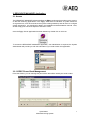
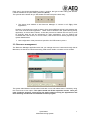
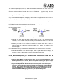
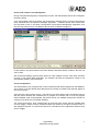
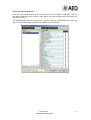
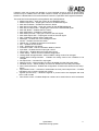
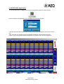
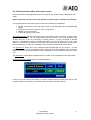
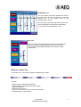
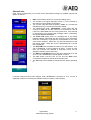
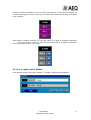
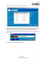
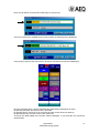
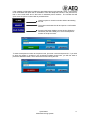
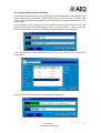
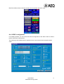
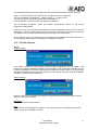
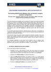
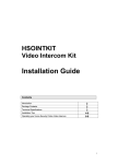
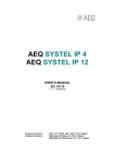
SYSTEL-6000
USER’S MANUAL
ED. 12/04
Systel 6000
Multiconferencing System
INDICE:
1.- Introduction
2. EASY SERVER Application. Start-up and Operation.
3. RESOURCE MANAGER Application.
3.1 Access
3.2. CODEC Phone Book Management:
3.3. Resource management.
4. SYSTEL SHARING SERVER Application.
5. SYSTEL SHARING SETUP Application.
6. SYSTEL 6000 Application
6.1 Functional description of the user screen
6.2. How to make a call at 64kbps.
6.3. How to make a call at 128kbps.
6.4. CODEC configuration.
6.5 Tool bar Options
WARRANTY FOR AEQ SOFTWARE PRODUCTS
Systel 6000
Multiconferencing System
2
1.- Introduction.
The Systel 6000 software allows to establish a MULTICONFERENCING system with up to 20
simultaneous lines through the transparent control of EAGLE or COURSE ISDN audiocodecs or
permanent connection (analog hybrids, 4w connections with other studios,...) performing
automatically the required cross-points in the IMPACT-CADDY matrix.
The application controls the AEQ E@sy devices in real time, performing the functions of a
Multiconferencing and Multiplex System:
Allows phone calls to be generated or received and integrated in multiconferencing
groups with other phone lines and 4-wire audio lines from the studio or remote ones.
Each Systel 6000 multiconferencing group, called ‘Multiplex’, creates a ‘N-1’ lines
group to send each line mixed audio from the entire group, called ‘Master’, except its
own.
Each participant in the Multiplex can be set in one of these states:
o ON AIR - Receives and contributes to the group (Master).
o INTERCOM - speaking exclusively with the operator or presenter.
o WAIT - only receives from the group.
o PFL - its audio is sent to a listening circuit.
o AUX - its audio is sent to an auxiliary program.
The AUX circuit can be used as a secondary Master signal, creating two busses for the
program. In addition, it can be used to send one or more lines to a recoding bus. It is
possible to create up to 8 auxiliary circuits and to define its operation, as 2 wires or 4
wires.
It is possible to create up to 8 intercommunication circuits in order to speak with one,
some or all the lines.
BENEFITS AND SPECIAL FEATURES
• Allows multiconferencing, intercom, cueing and on-air functions to be created, with
circuits from phone lines, ISDN links or physical audio lines, microphone or internal,
digital or analog.
• Scalable, both in number and type of circuits and in number of controls.
• Incorporates and expands the functionality of the old AEQ Systel 3000 system, and
makes it more flexible.
• Incorporates and expands the functionality of the old 4-wire analog multiplex consoles,
typical of sports broadcasts from multiple locations and commentators, and makes it
more flexible.
• Input and output gain control for each line.
• Multi-user and multitasking.
• Possibility of centralizing all codecs central control room.
Systel 6000
Multiconferencing System
3
2. EASY SERVER Application. Start-up and Operation.
This area is described in detail in the installation and administration manual. Here, we will
simply point out those aspects of interest to users.
Before Systel 6000 is started up, the E@sy server must be open. If you cannot find the E@sy
server icon on the task bar that shows the application is running in the background: tareas:
Look for this icon on the Windows desktop
click on it and make sure the icon is now on the taskbar. If this icon is not on the taskbar, you
will not be able to use Systel 6000.
Closing
This server program remains resident while E@sy equipment that allows the Systel
6000 function to be performed is being controlled
To stop the program from running and close the application, it is necessary to right click again
on the icon located on the taskbar and press the Exit option. Do not do this before having
closed the Systel 6000 and Systel Sharing Server applications, which we will describe next, and
in that order.
IMPORTANT: to avoid accidental connection failures, the PC will not turn off if the
server application is not first closed.
Systel 6000
Multiconferencing System
4
3. RESOURCE MANAGER Application.
3.1 Access
The RESOURCE MANAGER software defines the E@sy equipment that makes up the system,
so that the remaining applications in the E@sy Suite have an indication of system resources.
As a general rule, it will be used when the system is being started up and will serve to configure
system expansions. It is described in detail in the installation and administration manual. Here,
we will simply point out those aspects of interest to users.
Once the E@sy Server application has been started up, double click on this icon:
To access the RESOURCE MANAGER application, user identification is required; the System
Administrator will provide you with this information if you need to enter this application:
3.2. CODEC Phone Book Management:
From this window, you can manage the phone book that will be used by the audio codecs.
Systel 6000
Multiconferencing System
5
Each entry in the phone book defines a name, a number, the type of audio coding and whether
it will be available in the quick-dialing windows (Quick).
The symbols at the bottom let you add, delete and edit each phone book entry.
The phone book defined in the Resource Manager is common to all E@sy Suite
applications.
However, it would be more usual to want to have several different phone books besides this
one in the SYSTEL 6000 application. These must be defined in the Systel Sharing Setup
application, as we will later indicate, so that the phone book defined here will not be used
for SYSTEL 6000 but will be operational for other applications, such as EAGLE and
COURSE Real Time Control; so in most cases, it will not be used or will be prepared by the
System Administrator.
See configuration of the phone book specific to SYSTEL 6000 in point 5
3.3. Resource management.
The Resource Manager application also lets you manage the use of resources through the In
Use menu, so that the circuits that are being used at each studio or location can be verified:
The system administrator can see what circuits are in use, and release them if necessary using
the ‘Free Circuit In Use’ option. This option would cut off the respective circuits. Once you
have finished a program, avoid leaving the studio without closing the applications and
thus releasing circuits that are needed for another program.
Systel 6000
Multiconferencing System
6
4. SYSTEL SHARING SERVER Application.
Operation:
This functions as a communication server between the E@sy Server, Systel Sharing Setup and
Systel 6000 applications.
To run the program, the E@sy Server must be running.
When you double click on the program icon, a new icon is displayed next to the E@sy Server
icon:
The Systel Sharing Server application must be running for the Systel Sharing Setup and
Systel 6000 applications to work.
5. SYSTEL SHARING SETUP Application.
Operation:
This lets you perform the specific user and environment configuration of the Systel 6000
application.
Once the Systel Sharing Server application is running, double click on the icon.
To access the SYSTEL SHARING SETUP application, user identification is required; the
System Administrator will provide you with this information if you need to enter this application.
The Administrator will perform the following configurations from this application:
Creating a location.
The circuits (physical connections) that define the Systel 6000 system are configured:
In the first place, a name is indicated for the location. This location will normally correspond to
a studio. Likewise, a description may be entered for the MASTER and AUX signals.
Systel 6000
Multiconferencing System
7
The matrix’s input/output circuits or “audio ports” that the MASTER, PFL and AUX control
signals connect to are defined. The intercoms assigned to this location are also defined,
according to the number of people who have to handle calls. In other words, as many
intercoms will be enabled as telephones or intercoms are installed to prepare and operate calls.
Creating ‘MULTIPLEX’ configurations.
Once the locations have been configured, the Administrator configures the user screens to
carry out the different multiplexes, assigning a name to each configuration so that the user can
select the appropriate multiplex upon start-up.
The ‘Intercom Mode’ field defines whether the Intercom acts with a normal or summing function:
NORMAL: The four-wire connection is established, so that the program and the return are
interrupted to connect the commentator with the intercom.
SUMMING: The commentator’s program is not affected and the intercom signal is summed with
the commentator’s return.
In the “Aux mode” field you can configure the auxiliary in normal or master mode:
Normal Aux Mode: With this option marked, when a call is on the air and that same
channel is in an auxiliary circuit, the auxiliary will remain active when the call is shifted
to WAIT status.
Master Aux Mode: If you configure the auxiliary in master mode, when a call in an
auxiliary circuit is shifted from on-air to wait status, the auxiliary will remain deactivated;
similarly, when the call shifts back from wait to on-air status, the auxiliary will be
activated again.
In the Matrix Mode field you can determine whether this mode will be normal or protected:
Normal Matrix Mode: If you select this option, when a Systel 6000 session is begun, the
system will clean all the lines in the matrix if the matrix is connected.
Protected Matrix Mode.
In the Matrix Mode field you can determine whether this mode will be
normal or protected:
Normal Matrix Mode: By selecting this option, you will ensure that when a Systel
6000 system session is started, all the crosspoints affecting the input or output
lines used by the Systel 6000 will be deleted from the IMPACT matrix.
Protected Matrix Mode: By selecting this option, you will ensure that when a
Systel 6000 system session is started, all the crosspoints that affect only the
input and output lines used by the Systel 6000 will be deleted from the IMPACT
matrix. NOTE: In this operational mode, if there is an input being sent into the
on-site MASTER line, this crosspoint will be maintained, and therefore will be
added to the MASTER signal generated by the Systel 6000 system.
Systel 6000
Multiconferencing System
8
Phone book selection and management
During the Systel Sharing Setup configuration process, the Administrator selects and configures
the phone books.
If the ‘Phone-Book’ field is left blank, the phone book used will be the common phone book,
which was defined in the Resource Manager application. A different phone book created from
the drop-down menu in the ‘Basic Configuration/ Phone Book Management’ application may
also be used, which lets you use different phone books for different programs.
In this window, two phone books have been defined, and three entries created in the first one
can be seen.
We recommend keeping a phone book active for each multiplex so that, when lines are taken
off hook in the Systel 6000 application, the software will allow the telephone number to be
automatically saved in the phone book.
Circuit configuration
The Administrator now configures the circuits (CODECS) that will be assigned to that Multiplex.
The number of circuits defined here determines the number of CODEC lines that will appear in
the control window.
There are two ways to select circuits. The first one is to select what Codec card will be used, so
that the phone numbers are maintained for a program; the second one is to let the program
select available cards, as appropriate, which does not let you establish fixed phone numbers in
a program, but does give you greater flexibility:
The “Direct Connection” lines corresponding to those four-wire circuits that are created apart
from the “E@sy” codecs are also configured, either with studios or through microphone lines, or
with telephone hybrids or Codecs that cannot be controlled from the application because they
are not “E@sy”.
Systel 6000
Multiconferencing System
9
Group and user management
Here, the Administrator defines what user groups may use a multiplex configuration. He can
also define what users have access to each group, and what privileges each user group has
over user functions.
The ADMINISTRATOR has no restrictions. We can create an ‘OPERATOR’ level where we
restrict some functionalities according to the tasks each one performs:
Systel 6000
Multiconferencing System
10
Likewise, other user groups with broader or more restricted access to each of Systel 6000’s
functions may be created, which will make it easier to create very productive work environments
based on a differentiation of functions between Producers, Operators and Program Presenters.
The restriction levels managed by the application are specified below:
Master Input Gain – Input gain control for the MASTER signal.
Master Output Gain – Output gain control for the MASTER signal.
Main IntCom Button – Enables the intercom button.
Main IntCom Input Gain – Input gain control for the INTERCOM signal.
Main IntCom Output Gain – Output gain control for the INTERCOM signal.
Main PFL Button – Enables the PFL button.
Main AUX Button – Enables the AUX button.
Main AUX Input Gain - Input gain control for the AUX signal.
Main AUX Output Gain – Output gain control for the AUX signal.
Dial – Enables the button used to make calls.
Messages – Enables use of the message function.
IntCom – Enables the Intercom button.
Wait/On Air – Enables the wait and on air buttons.
PFL – Enables the PFL button.
AUX – Enables the AUX button.
Information Label - Lets the information label be viewed.
Input Gain – Enables the line’s input gain control.
Output Gain – Enables the line’s output gain control.
Codec Setup – Allows access to CODEC configuration.
Coding Mode Change Allowed - Allows CODEC coding mode to be changed.
Coding Mode Change Allowed - Enables the coding mode of the CODECS to be
changed.
Pfl Output Gain – Controls PFL output gain
Add Aux Circuit – Allows auxiliary circuits to be added from the side panel setup
Disabled circuits – Allows auxiliary circuits to be disabled from the side panel setup
Save Levels & Phones – Enables the configuration of levels to be saved from the setup
button
Right Master Panel – Activates or deactivates the front panel Output Gain – Enables
operators to act on the line output gain control
Agenda (Phone book) – Allows the agenda or phone book to be displayed and used
when a call is made
Save Phone online – Enables telephone numbers to be saved when a call is terminated
Systel 6000
Multiconferencing System
11
6. SYSTEL 6000 Application
To use the application, the E@sy Server and the Systel Sharing Server must be running.
Double clicking on the application icon will display an identification window:
If the user has more than one permitted location, these will be displayed so that he can choose
one.
Then, if the user can choose from among different multiplexes, these will also be shown.
If there is only one possible multiplex configuration, the control screen will open up directly.
Systel 6000
Multiconferencing System
12
6.1 Functional description of the user screen.
Once the SYSTEL 6000 application has been accessed, the control screen is divided into four
areas:
Upper right-hand and mid-screen area: General controls (master, auxiliary and intercom).
The right-hand area of the screen gives access to the following functionalities:
Control of the master input and output levels of the MASTER, AUX and INTERCOM
signals
Placement of all lines in intercom, PFL or AUX status
Addition or removal of lines
Loading and saving audio levels
The INTCOM button puts all the lines that have a connection in Intercom mode. In other words,
by pressing this button, we can make general announcements to all correspondents, both
whether they are on the air (”ON AIR”) or waiting (“WAIT”), or even connected to another
intercom. Nevertheless, when we release the button, each circuit will go back to its former
status, so if we want to get answers to our general announcement, we will have to connect each
of the channels to our intercom, according to the procedure we will look at in due course.
The general PFL button “all to cue” activates and de-activates the PFL for all lines. In other
words, if we press it once, all correspondents, mixed, go to the PFL speaker, and if we press it
again, the cue for all correspondents is reset, regardless of their status before going to “all to
cue.”
The AUX button sends all the multiplex lines to the AUX circuit, regardless of their prior status.
Pressing the SETUP button opens the following window:
From here you can save (SAVE button) or retrieve (LOAD button) the audio levels set for each
multiplex session and location. The system stores the levels of all the channels.
Systel 6000
Multiconferencing System
13
You can also use this configuration window to add (ADD button) or disable (DISABLE button)
lines. When you wish to add lines, press ADD and the following screen will be displayed:
In this window, the lines that are associated with a codec are displayed
in green (this is configured in the Resource Manager). To add a line,
simply select it and press ADD.
The LEVELS button adjusts the audio levels of the ON-AIR, PFL, INTERCOM and AUXILIARY
signals. If you press each one of these, the following windows will be successively displayed:
ON-AIR level
The Input Gain fader adjusts the level of the return signal that will be sent
from an auxiliary output of the console into the correspondents’ circuits, both
when they are ON AIR and when they are listening off-program—that is, in
WAIT status.
The Output Gain fader regulates the level of the signal that will enter the
console from Systel’s mix of the signals from the correspondents’ ON-AIR
circuits.
INTERCOM level
The Intercom Input Gain fader adjusts the level of the
Intercom signal that will be sent, when the Intercom
key is pressed, from the Intercom microphone to all of
the correspondents’ circuits, both when they are
connected to your Intercom or to another Intercom, or
when they are ON-AIR, or even if they are listening
off-program—that is, in WAIT status.
The Intercom Output Gain fader adjusts the level of
the signal that will enter the Intercom speaker or
headset from Systel’s mix of the signals in the
correspondents’ circuits that are connected to your
intercom.
Systel 6000
Multiconferencing System
14
AUXILIARY level
The Aux Output Gain fader regulates the level of
the signal that will enter the auxiliary circuit from
Systel’s mix of the signals from all the
correspondents’ circuits.
The Aux Input Gain button adjusts the level of the
return signal that will be sent from the auxiliary
circuit to all the correspondents’ circuits.
PFL level
The PFL Output Gain fader adjusts the level of the signal that is
sent to the output configured as PFL and which is normally
connected to a self-amplified speaker or to a specific mixing
console input.
Bottom or status line
The bottom line on the screen indicates the application’s status:
It shows:
- Which user has opened the application.
- Which multiplex configuration has been chosen.
- What the location is.
- What the user’s level is.
- How many sessions are open on the same multiplex.
- Operating mode – real or demo.
Systel 6000
Multiconferencing System
15
Systel 6000
Multiconferencing System
16
Channel area
Each line is corresponding to a 4-wires circuit, associated normally to a CODEC channel and
appear as follows:
•
•
•
•
•
•
•
•
•
DIAL is the button that lets you access the dialing menu.
The number in the upper right-hand corner, ‘1,’ is the number of
the channel in the multiplex configuration.
The counter under the channel number, ‘00:00,’ is a counter that
indicates how long a connection has been waiting.
The alphanumeric field, ‘34910000010,’ shows when idle the
number of ISDN line and the number it is connected to, and its
name if it is associated with one in the phone book. If the channel
is connected to a four-wire line with no E@sy codec, it will display
the legend “Direct Connection. “
The blank field allows memo or message text to be written
between stations associated with the channel to give information
about the momentary or permanent correspondent to the other
users of the multiplex. When idle, only the first characters of the
text will be shown. When the cursor is positioned over it, the full
text is displayed.
The INTCOM button activates the intercom on that channel. If no
call is established, it will not appear as active. If there is more
than one intercom line defined, a drop-down menu will be
displayed, allowing you to select one.
The WAIT and ON AIR buttons put the call in wait mode or on the
air. If no call is established, it will not appear as active
The PFL button puts the line on cue and the AUX button
connects the respective channel to the auxiliary bus.
The C01 label can be edited to indicate who the person speaking
is.
If several intercoms have been defined, when INTERCOM is pressed on one, a menu is
displayed to select from among the available intercoms (three in the example)..
Systel 6000
Multiconferencing System
17
Similarly, if there are several PFLs in your system, pressing PFL on a line (in our example, line
number 2) will bring up a menu in which you can choose among the cues you wish to use (three
in the example).
With regard to auxiliary channels, you can also select up to eight by pressing AUXILIARY,
which will bring up a screen in which you will also be able to configure the number of
wires this auxiliary will have: four or two.
6.2. How to make a call at 64kbps.
Press the DIAL button for the line in question. The dialing window will be displayed:
Systel 6000
Multiconferencing System
18
Press the ON/OFF button at the top so the following is shown:
In the Number field, the number to be called is entered. To do this, you can type directly or use
the dial pad, pressing on the icon. If the number is in the phone book’s quick access numbers,
you will have to double click on it, and the number will be displayed in the Number field.
Once the coding mode (Audio Mode) has been selected, press OK to close the window and
initiate the call:
The call underway will be displayed in this window.
Systel 6000
Multiconferencing System
19
Next, the call will be connected and it will begin to synchronize:
Once the call has been established and synchronized, the following will be displayed:
Press Close to return to the main screen, where you will see the connection established:
Now the INTCOM, WAIT, ON AIR, MASTER and AUX buttons will appear as active.
By pressing INTCOM, the intercom line is activated.
By pressing WAIT, the line is put in wait mode and the counter at the top starts up.
By pressing ON AIR, the line is sent to the master bus.
At the top, the label related to the number called is displayed. If you press this, the connection
will be broken.
Systel 6000
Multiconferencing System
20
If the multiplex configuration includes an associated phone book (agenda), when a call is about
to be terminated, the option will be available to save the telephone number in the phone book,
both in the normal book and in the book of unwanted phone numbers. The window that will
open when the phone number label is pressed will be:
Use this option to close this window without terminating
the call.
This button terminates the call and opens a confirmation
window.
Pressing this button displays a new window (following
illustration) that will enable you to save the telephone
number in the phone book.
To save the telephone number to the phone book, just enter a name and press OK. If you wish
to store the number in question in the unwanted numbers phone book, you will first have to
press the WANTED button, which will leave window looking like this:
Systel 6000
Multiconferencing System
21
6.3. How to make a call at 128 kbps.
If you want to establish a call with high audio quality, the 48 MONO MPEG 128k and AEQ LD-2
coding modes may be used. Both modes require the use of both channels of a basic ISDN
access. For this reason, both channels must correspond to the same COURSE card or the
same EAGLE.
In the first place, you must reserve two of the multiplex lines for one of these connections, and
make the call from the card corresponding to line 1 of the audio codec. To see it, press the
DIAL button, and make sure that L1 is displayed in the selected field, as in this figure:
Then, press ON/OFF to enter the dialing window to type in the number to call, as well as the
coding mode:
When the call has been established, the following will be displayed:
Systel 6000
Multiconferencing System
22
Both lines will be shown in the main screen, but one of them cannot be used:
6.4. CODEC configuration.
In the dialing window, you can access the internal configuration of the audio codecs in order to
perform advanced configurations.
The meaning of all the parameters is explained in the user’s manual of the respective audio
codec.
Systel 6000
Multiconferencing System
23
The parameters that may be most used within the Systel 6000 application are the following:
ISDN - From this window, you access the line configuration for the equipment.
The type of interface is selected (S – 4 wires, RJ45 or U – 2 wires, RJ11).
The type of protocol is selected (EUROISDN or NATIONAL-1).
If the NATIONAL-1 protocol is used, the SPIDs are indicated.
The AUTOSYNC parameter makes the CODEC automatically search for the remote
equipment’s coding mode.
In the G711 menu, the operation of the telephone mode is established, which may be normal or
extended (to connect to other AEQ hybrids), as well as the activation of automatic remote echo
cancellation, which in some cases will improve the quality of the transmission.
In the Off-Hook menu, the CODECS can be defined to automatically take calls off-hook or to
emit a signal so that the user can decide when to take them off-hook.
6.5.- Tool bar Options.
Set-up
Assign Location
If we assign a location to a work station, while entering the application from the station, it will
directly go to select the defined multiplex for that position, which avoids the possibility of trying
to start up a Multiplex of which the audio cables correspond to another studio. If you log in as an
user with administrator rights, this option does not act and will be within the reach all the defined
multiplex, no matter what its location is.
Assign Intercom
Select the intercom circuit that we are going to communicate from when pressing the general
intercom from that work station.
Kill session
It allows to close the Systel session.
Ring
It selects if the incoming calls are ringing or, due to the proximity of microphones to the work
station, simply are visualised on screen.
Systel 6000
Multiconferencing System
24
WARRANTY FOR AEQ SOFTWARE PRODUCTS
AEQ warrants that this product was designed and manufactured according to a Quality Assurance system that
is type approved and certified in accordance with ISO standard 9001/2002. AEQ thus warrants that the
required testing protocols were followed and executed to ensure the correct functionality of the product, as well
as its specified technical characteristics.
Both the general design and manufacturing protocols and the particular protocols applicable to this
unit are properly documented.
AEQ warrants that the software delivered is compliant with the specified technical and functional
characteristics.
AEQ warrants that the medium on which the software is delivered has been verified, and that the hardware key
that enables the software to be used works correctly in the planned scenarios.
AEQ warrants the disks delivered.
1.- This warranty does not exclude nor limit any of the customer’s legally recognized rights.
2.- The warranty period is twelve months counted from the date on which the first customer purchases the
product.
To execute this warranty, the customer must inform the authorized AEQ distributor or, in the absence of such
a distributor, an AEQ sales office or the AEQ Technical Assistance Service, within thirty days following the
appearance of a defect in a product that is under warranty, and provide a copy of the purchase invoice and the
serial number of the product.
The AEQ Technical Assistance must, moreover, give its prior express approval of the shipment to AEQ of
products to be repaired or replaced in application of this warranty.
No product returns that do not comply with these terms will be accepted.
3.- AEQ shall repair or replace the defective hardware key upon its return, if it has agreed to replace it,
including the labor required to repair the key, provided that the failure of the key is due to defective materials,
design or labor. The repair shall be done in AEQ’s Technical Assistance Service shops. This warranty does
not include transport or shipment to the shop, nor return shipment.
AEQ shall replace defective support media or product documents. In the event that hidden defects appear
whose existence was unknown at the time the software was delivered, AEQ shall provide the version that will
enable these defects to be obviated.
4.- Any functional defects derived from the use of a hardware support that has not been type approved by AEQ
shall be
expressly excluded from this warranty.
Also excluded from the warranty are defects arising from the use of non-AEQ software whose utilization has
not been expressly approved or supplied by AEQ, both as regards operating systems or other computer
applications and their different versions.
5.- No extension of the warranty period shall be applied to products that are repaired or replaced as part of its
execution.
6.- This warranty shall not be applicable in the following situations:
use that contravenes the instructions given in the user’s manual; violent manipulation; exposure to damp or to
extreme heat or atmospheric conditions, or sudden changes in such conditions; lightning; rust; unauthorized
modifications or connections; unauthorized openings or repairs of the product; misuse; spillage of liquids or
chemical products.
7.- AEQ shall under no circumstance and in no case be responsible for any type of damages, whether direct or
indirect, that may be derived from the use or the impossibility of using the software.
Systel 6000
Multiconferencing System
25