1
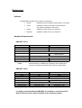
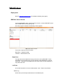
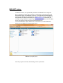
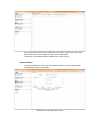
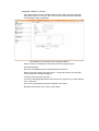
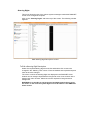
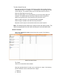
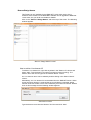
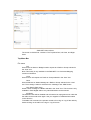
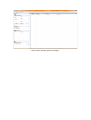
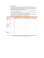
Icom (UK) Ltd RMS-Net User Manual V 3.0.28 June 2010 RMS-NET Table of Contents Introduction..........................................................................................................1 Deployment ........................................................................................................2 Software..................................................................................................................................2 Hardware Requirements.........................................................................................................2 RMS-NET Server.................................................................................................................2 RMS-NET Client..................................................................................................................2 It is highly recommended that RMS-NET be installed on a stand alone PC with all relevant service packs installed for the operating system.................................................................2 Installation...........................................................................................................................3 Firewall Considerations.......................................................................................................3 Getting Started .......................................................................................................................4 Procedure...............................................................................................................................4 Dongles ..............................................................................................................................4 Demonstration Mode...........................................................................................................5 Radio Identities....................................................................................................................5 Groups.................................................................................................................................5 Network Users.....................................................................................................................5 RMS-NET Suite...................................................................................................6 Program Group.......................................................................................................................6 RMS-NET Server................................................................................................7 Deployment.............................................................................................................................7 RMS-Net Server Screen.........................................................................................................7 Right Pane...........................................................................................................................7 Left Pane.............................................................................................................................7 Hidden Admin Tools............................................................................................................9 RMS-NET Admin ..............................................................................................11 Administration Features........................................................................................................13 Users & Groups.................................................................................................................13 Table View.........................................................................................................................14 Network Users...................................................................................................................15 Database Backup and Restore..........................................................................................17 RMS-NET - Server Features.................................................................................................20 Feature Selection..............................................................................................................20 Server Features.................................................................................................................23 Timers...............................................................................................................................24 Comm Ports......................................................................................................................26 RMS Features...................................................................................................29 General features...................................................................................................................29 RMS RX status..................................................................................................................29 RMS TX Status..................................................................................................................30 Pre-Stored Text Message..................................................................................................31 Steering Digits...................................................................................................................32 Selcall RX Codes...............................................................................................................33 Selcall TX Codes...............................................................................................................34 Beacon/Badge Names.......................................................................................................36 Help...................................................................................................................................37 About.................................................................................................................................37 RMS-NET Client................................................................................................38 Installation.............................................................................................................................38 Logon....................................................................................................................................39 Main Client Window..............................................................................................................39 Top Menu Bar....................................................................................................................40 Left Pane...........................................................................................................................42 Right Pane.........................................................................................................................43 Emergency Message Functions........................................................................................47 Options - Settings..............................................................................................................48 RMS-NET Reporter...........................................................................................51 Page i Count on Us RMS-NET General.................................................................................................................................51 Logging On............................................................................................................................51 The Reporter Screen.............................................................................................................52 Left Pane...........................................................................................................................53 Right Pane.........................................................................................................................53 RMS-NET Updates ...........................................................................................55 Glossary............................................................................................................55 Notices...............................................................................................................57 Trademarks ..........................................................................................................................57 Copyright Information............................................................................................................57 Rights and Responsibilities...................................................................................................57 Liabilities...............................................................................................................................57 Page ii Count on Us Introduction RMS-NET Suite is a modern software package providing an organisation with a tightly integrated management and safety system capable of local or wide area coverage. The system incorporates a number of components, many of which are already found in today's businesses. RMS-NET brings these components together, integrating them into one centrally managed, cohesive network providing positive benefits for management, staff and public alike. When used in conjunction with other modern security systems, RMS-NET can provide a detailed view of activity and staff deployment. The system is designed to be fully interactive, ensuring dispatchers/supervisors are able to monitor and respond rapidly to situations as they occur. The heart of RMS-NET Suite is the central computer server which receives information from authorised two-way radio users and provides a real-time view of staff resources deployed in or around a building, high street, docks, town or almost any other workplace, whether local or remote. In addition the centralised nature of the system ensures rapid response to incidents as they occur as well as the managed prevention of potential incidents. Note: This application should not be used as a safety critical product. Deployment Software The RMS-NET program Suite consists of 4 programs: Server Installed on the PC where the base radio is connected Client Installed on each PC that will access the Server (can also be installed on Server PC) Admin Installed on either a Server or Client PC Reporter Installed on either a Server or Client PC Hardware Requirements RMS-NET Server CPU RAM Hard Drive Network Ports Operating System Monitor Graphics card * Note Minimum Optimum 1 GHz *(see note) 2 GHz *(see note) 1GB 2GB 100GB 250GB Network Adapter 10/100 Mbps 2 x USB 1 x USB + 1 x Serial Per Radio Channel Windows XP, Windows 2003, Windows Vista 17” 19” 1024x768, 16 bit 1600x1200, 24 bit No Intel Celeron or AMD Duron processors to be used even if they are of a higher specification than minimum specification. RMS-NET Client CPU RAM Hard Drive Network Other Operating System Monitor Graphics card Minimum Optimum 1GHz *(see note) 2 GHz *(see note) 1GB 2GB 100GB 250GB Network Adapter 10/100 Mbps 1 USB port 1 USB port Windows XP, Windows 2003, Windows Vista 17” 19” 1024x768, 16 bit 1600x1200, 24 bit It is highly recommended that RMS-NET be installed on a stand alone PC with all relevant service packs installed for the operating system. Installation The RMS-NET software suite is supplied on one CD. To operate the software fully an RMS-NET dongle is also required (see page 4). Do not insert the dongle before the RMS-NET software suite is installed. To install, insert the CD into an appropriate drive on the PC. A splash screen will appear after a few seconds. Click “Setup” and follow the on-screen instructions to install the software. There is also a link labelled “Manual”, leading to this document. Once installation has been successfully completed, restart the PC before running the RMS-NET Suite of software. Plug in your USB Dongle. The PC will detect the dongle as a new piece of hardware and will install the appropriate drivers from the RMS-NET CD. You should now be able to run the software. Microsoft .NET Framework Version 2.0 must be installed on your PC to run this software. During the installation process, if this software and version is not already installed on the machine, it will be offered for installation. If this occurs, select “Yes” to install and it will over-write any existing installation. Electing not to install .NET Framework Version 2.0 will render RMS-NET inoperable. During the installation you will be prompted if you would like to update a RMSNET Version 2 database. If you click “Yes” then you will need to select the Version 2 database. Once selected, the database will be updated for use on RMS-NET Version 3. Depending on the size of the database, this update process can be quite lengthy. After installation, if you wish to update a Version 2 database, you can do so by running the RMS-NET DU application located in the following directory C:\Program Files\Icom UK Ltd\RMSNET\Utils\Database Warning: If you opt to restore a Version 2 database, the current installed database will be lost. Firewall Considerations When installing all RMS-Net applications, all firewall and anti-virus software should be turned off. You should also consider disconnecting any Internet connection during this time. Some firewalls / anti-virus software require permissions to be set to allow the RMS-NET applications to communicate with each other. When using network clients, permissions may need to be granted within the firewall product. Several operating systems now incorporate a firewall product within them as standard, and great care should be taken to ensure permissions are granted within those products. Ports required are TCP, 8737 for RMS-Client, 8738 for the RMS-Server and 8739 for RMS-Reporter. These should be set for both way (in and out) communication. Client connections to a remote server, using the Internet, should be configured using VPN (Virtual Private Networking). Please refer to your radio or computer system supplier for this. If Internet connectivity is already available at each site to be connected, (broadband preferred) then this is a virtually free option. All screen saver and power save options should also be disabled on any computers operating the RMS-Net software. Getting Started Before using RMS-NET some thought should be given to the structure and intended operation of the entire system. Planning of Radio Identities, User Groups and the number of Network Users required at this stage will ensure the necessary information is to hand when completing the configuration screens. Consideration should be given to the naming conventions used to ensure that user and radio identities are clear and unambiguous. Please discuss your operational requirements with your radio dealer who will help to plan and organise your radio system programming. Procedure The RMS-NET software needs some initial setup. The following steps are needed to establish a basic system. 1. Install the software as above; ensure the Dongle is connected and restart the PC. 2. Locate the RMS-NET Suite Program Group. 3. Start RMS-NET Server (see page 7). NOTE: RMS-NET Server needs to be running at all times when running other RMS-NET programs. 4. Locate the RMS-NET Suite program group. 5. Start RMS-NET Admin 6. Add Radio Operating Channels. 7. Add Radio ID’s. 8. Add Group ID’s as required. 9. Add Network Users (At least one is required). 10. Attach Radio ID’s to Network Users as required. Once the system is operational, RMS-NET Server features may be configured to enhance the system operation. Dongles Each installation of the software will require a Dongle. There are two types of Dongle - these are colour coded: RED or BLUE. The RED Dongle is for use where the RMS-NET Server software is installed and also permits a client installation on that machine. The RED Dongle is individually programmed to enable the functions purchased for each installation. The BLUE Dongle is for use where the RMS-NET Client software alone is installed. For full use of the software you must have a Red Dongle connected to the PC running RMS-NET Server and a Blue Dongle for each additional client machine accessing that server. Demonstration Mode Without a Dongle, the software runs in demonstration mode. In this mode, the software will have all the functionality of the full version except for the number of users that can be connected. A message will be displayed on the screen showing that the software is in demonstration mode. Radio Identities Each radio on the system has a unique identity. Radios will be configured for your system by your supplier. Each radio identity has to be entered into the software. This can be done remotely if facilities and security allow. Groups A group consists of a number of users. Users can be registered to multiple groups. Network Users A Network User is an operator that has access to one or more RMS-NET programs. They have either selected radio users / groups assigned to them or access to all radios / groups. RMS-NET Suite Program Group During installation, a folder will be placed on the Desktop containing shortcuts to the modules chosen for installation on the PC. The shortcuts can be dragged or copied to your Desktop or included in the “Startup” folder if required. A program group called RMS-NET Suite is also added to the “All Programs” option from the Windows Start button. RMS-NET program group RMS-NET Server Deployment Refer to Hardware Requirements for hardware suitability (see page 2). RMS-Net Server Screen To access RMS-NET Server, double click the shortcut, or select RMS-NET Server from the RMS-NET Suite program group. Once the program is started, the following screen appears. RMS-NET Server screen The screen is split into two main areas: Right Pane - Operational data Left Pane - Administrative tools. Right Pane The right pane shows data that is being received or sent by RMS-NET. These messages may be cleared at any time by pressing “Clear Messages” in the lefthand pane. Clearing the messages does not remove them from the database, it only clears this view. Left Pane On the left hand side are “Server Administration” tools. These are as follows: Serial Log Shows the input and output data streams of the RS232 ports. Query Radio This option sends a command to the connected radio, to check its RS232 communication status. If there is a problem with the radio then "Radio Error" will be displayed in the channel states window. Engineering Mode When engineering mode is selected, a tick is displayed against the option in the left pane and all types of message are displayed, regardless of other selections. Backup Database Throughout this manual there are references to backing up the database. If the Database becomes unusable it will be necessary to start again from a clean installation, unless you have such a backup. It is highly recommended to take backups on a regular basis. Refer to Database Backup and Restore on page 17 for more details. Minimise to Tray Minimises the Server application to an icon in the Systray in the bottom-right corner of the screen. RMS-Net Server icon in the Systray Clear Messages This option will clear the messages displayed in the right hand side of the screen. Messages are not deleted, just cleared from this screen view. All messages are stored in a database within RMS-NET and can be viewed in RMS-NET Reporter. Help There are two options located under the Help Menu: Help – Opens the help document. About – Displays the version number of the software. About window displaying version number Hidden Admin Tools There are several functions designed for engineering maintenance located in a hidden menu. To access these functions open the “Help – About” menu within RMS-NET Server. When presented with the above screen type the following (there is no prompt, just type): ineedhelp The following screen will be presented. Hidden Admin Functions – Stored Users Screen The first screen, “Stored Netusers”, displays all of the Network Users Login Usernames and Passwords. If you select the “Others” tab from the top then the following screen will be presented. Hidden Admin Functions – Others Screen From this screen you have the following options: Clear Log This option removes all call / message logs from the current database whilst retaining all of the system settings. NOTE: Once this data has been removed it is irretrievable. Always take a backup copy before using this function. Refer to Database Backup and Restore on page 17 for more details. Clear Queue Clears all queued messages in RMS-NET Client. Clear Send Queue Clears any messages that are waiting to be sent. Backup Locations This function enables you to change the default directory for all database backups. Backup To… Using this option you can do a single database backup to a different location than the normal backup directory, such as a removable USB drive. Restore From… Enables a backup database to be restored from a different location than the main backup directory. RMS-NET Admin In RMS-NET Admin, the operational parameters for RMS-NET are configured. During installation a folder will be placed on the Desktop containing shortcuts to the modules chosen for installation on the PC. The shortcuts can be dragged or copied to your Desktop or included in the “Startup” folder if required. Note that if the application is started automatically, the RMS-NET Server must already be running. During installation a program group called RMS-NET Suite is also added to the “All Programs” option from the Windows Start button. To access RMS-NET Admin double click on the shortcut, or select RMS-NET Admin from the RMS-NET Suite program group. RMS-NET program group Once the program is started, the following screen is presented. RMS-NET Admin Login screen Enter the Username and Password into the box provided. The first time RMS-NET Admin is run, the default username and Password must be used. Username: admin Password: admin If you are running the Admin program on the same computer as the RMS-NET Server then the “Localhost” box needs to be ticked. If the RMS-NET Server program is located on a different PC then un-tick the “Localhost” box and type the network address of the PC running the RMS-NET Server program in Server IP box. Press “Login” You are strongly advised to change the default RMS-NET Admin password. Refer to Edit Network User on page 16 to change password. Once you have logged in the following screen will be presented. RMS-NET Admin welcome screen Edit Buttons Several of the option screens in RMS-NET Admin are presented with the same set of edit buttons. Left Double Chevron Return to first entry Left Chevron Scroll entries Left Add New Add a new entry Edit Edit an existing entry Delete Delete an entry Right Chevron Scroll entries right Right Double Chevron Return to last entry While editing an entry, the Edit button will change to “Save”, thereby enabling the changes to be saved. Administration Features Users & Groups To add new or edit Users, click on “Users & Groups” (top left). The following screen is presented. User Manager screen In this screen, Users can be associated with their radio IDs. Radios will have been programmed by your Supplier with unique ID numbers. Before adding radios to the system a radio channel will first have to be added. See page for more details. The ID should be typed in the ID field and a Username associated with the radio in the Username field. This is the name that will appear in the database and other screens. The radio must then be associated with its User Type. These are the descriptions for types of radios supported by RMS-NET: User Individual Radio ID, unique to a single radio on the system. Group A group of Radio IDs. RMS-NET supports 3 types of signalling, BIIS1200 FFSK, Selcall and IDAS digital. If the User / Group uses Selcall signalling then the Selcall box needs to be ticked. Each radio can have a pre-set time that the Server automatically logs them off from the system. This time is set in the Logoff Time option. The Poll Timer (used for automatically tracking a GPS enabled radio) and the Loneworker Timer are also set on this screen. NOTE: If you do not wish the Server to automatically poll the radio set the Poll Timer to 0. Table View If you click on the Table View Tab at the top of the screen, the following screen is presented. This screen shows the User ID, Username, User Type, Logoff Time, Poll Timer and Loneworker Timer settings for each radio on the system. To edit any of the existing radios, double click on the User ID. Network Users To add / edit Network Users, click on “Network Users” in the left hand section. The following screen is presented. Network user management screen Add Network User To add a new Network User press the “Add New” button. Type a user name and password in the relevant windows. To associate radio Users with a particular Network User, use the left or right arrow buttons to select the required Network User. Click the “Edit” button. Select the radio Users from the unassigned window. Either double-click the radio User or highlight (click) and press the “Add” button. This will add individual radios to the Network User. Alternatively click the “All” button to assign all radio users to a Network User. These actions will move the radio to the “Assigned Users” window on the right of the screen. Once all the required radios have been assigned to the Network User, press “Save” to update the database. For other options on this screen, see Edit Network User, below. Repeat this procedure for any additional network clients. Edit Network User Using the left/right navigation buttons, select the Network User you wish to edit. For example, to change the RMS-NET Administrator’s password, scroll though the users until “Admin” is shown at the top of the right pane. Press “Edit” to edit any of the details for the Network User. Enter a new password in the box provided. It is recommended that this should not be a simple password such as date of birth, vehicle registration, maiden name, pet’s name, child’s name etc. Press “Save”. The new password will be saved to the Database. It is highly recommended to change the default Admin password. Note: If the password is lost, it will not be possible to access the functions of RMS-NET Admin. However, using the Hidden Admin Tools in RMS-NET Server (see page ) all usernames and passwords can be checked. Delete Network User Select the required Network User using the left/right buttons, then click “Delete”. Caution: there is no “Undo” function. User Rights The check boxes in the User Rights Section gives additional capabilities to the Network User. Some of the rights should be restricted to System Administrators or Senior Network Users. To add, select the Network User as above and tick the appropriate boxes. (A ticked box enables the User the Rights, a cleared box disables the Rights). Access Admin Gives the selected User Administrative rights within RMS-NET programs. Kill Radio Gives the selected user the ability to “Kill” or “Revive” (IDAS digital radios only) a radio, perhaps to prevent abuse in event of a radio being stolen. A Killed radio must be reprogrammed or revived before it can be re-used. Voice Gives the selected user the ability to use voice functions, if a microphone is connected to the base radio. Lone Worker Admin Gives the selected user the ability to use the Lone Worker functions in the RMSNET Client Program. Database Backup and Restore It is vital that the Database is backed up regularly. A daily routine should be established from the start. You must be aware that if the Database becomes corrupt, damaged or otherwise unavailable it will be necessary to start again with a new installation, unless a recent backup can be restored. Backup Click “Backup / Restore” (left-hand section of screen). The following screen will be presented. Backup Screen The Schedule section will automatically schedule backups to happen at certain time every day, as long as the Server program is running. To manually backup the database, press the "Backup" button. The Backup saves a snapshot of the Database at that specific time. Ideally this should be carried out at the same time every day i.e. at the end of a working day or shift. In addition, the use of a proprietary tape backup system for the Operating System, Programs and data is highly recommended. These backup files should be included in a rotating tape backup strategy and the tapes preferably stored off site. A typical backup strategy might include separate, daily backup tapes, used in rotation. A set of five or seven tapes, depending on your working practices, would typically be required. It is important that the latest backup tape is taken off site and returned before it is next required. In addition to the daily scheduled backup, the following weekly and monthly options are available. Weekly Options Tidy Tables – This automatically reorganises the database to reduce the size and improve its access speed. Create Archive Backup – The weekly backup is labelled slightly differently, stating the week number that it was created. Monthly Options The monthly options are the same as the weekly ones, but with the following added function. Delete Log – This options creates a backup labelled with the month that it was created, and then deletes all call log / message data. This ensures that the database sizes do not get too big. Both the weekly and Monthly options occur in place of the daily scheduled backup on the first day that the system is run in each week / month. All database backups are compressed in a standard .ZIP format to keep the file sizes to a minimum. They do not need to be extracted before use with RMS-NET. Restore Clicking on the Restore tab at the top of the screen will result in the following screen being displayed. Note: Restoring a previously saved Database will overwrite the current Database. All data and changes made since the date and time of that backup will be erased. Restore screen Previously saved backups will be listed in the top area of the screen. Click on the backup from which you wish to restore and press “Restore”. The current Database and configuration will be overwritten with the selected backup data. The default directory that the saved backups are located in is: C:\Program Files\Icom UK Ltd\RMS\Server\Backup This location can be changed using the Hidden Admin Tools in the Server program (see page ) Note: After a Restore operation, the Server and Client program must be restarted. A message prompt is given to remind the user. RMS-NET - Server Features Click “RMS Server Features”. The following screen appears. Server Features screen Feature Selection Logon Acknowledgement If the “Logon Acknowledgement” option is enabled, the RMS-NET system will reply to a “log on” or “log off” status from a radio with a status message e.g. “LOGGED ON OK”, “LOGGED OFF OK”. This option is useful to give a radio user confirmation that they are successfully logged on to the system. You can change the sent acknowledgement status by typing the desired TX status into the Logon Answer and Logoff Answer boxes (see page 29 for instructions on how to set up an RX status). Note: As standard, BIIS radios emit a double beep for successful transmission of a message and display “call fail” for an unsuccessful message. The radio can hold off a transmission on a busy channel, so the radio user could miss the double beep and be unsure whether they are successfully logged on. The feature is provided to circumvent this problem. Open Mute If this option is enabled, the RMS-NET system will send a Voice Call back to the radio that has just logged on, opening their receiver mute. The radios on the system will then all be open channel, which would create an all informed network like a standard CTCSS radio system. Note: By default BIIS radios are closed mute, they need to make a call or receive a call to open the mute. This may not be desirable if adding BIIS radios to an existing system or the customer does not want to place an individual call or group call. Speak to your dealer for advice on the best radio protocols for your system. Queue Features Queuing If queuing is enabled, text messages transmitted from a RMS-NET Client will be queued for a radio user until they have acknowledged receipt of any previous messages. This feature is useful for simple radio operation because there is no need to scroll through a list of received text messages and the possibility or deleting or missing a message is reduced. After the user has been sent one message, any subsequent messages will be queued until requested by the radio user. Reminders If reminders are enabled, a status is sent to the radio reminding the user that they have unread messages queued for them. The status sent is defined in the "Reminder Status" box. The “Reminder Time” can be set in minutes; this will set how often the status message is sent. The reminder status does not overwrite any previous text messages sent. When the radio user replies with a “Next Message” status confirming the previous message was read, RMS-NET will send the oldest queued message for that radio. This can continue until the user’s queue is empty. When there are no remaining messages queued, a “Message box Empty” status is sent to the user. GPS Poll Status If the RMS-Net Mapping Client is to be used the status sent to poll the GPS location of radio needs to be set. This is a common status number for both BIIS1200 and IDAS digital radios. The default setting is status 24. Emergency Features If the emergency features are enabled, when an emergency is received from a radio, the text ID (e.g. Radio ID 1485 = Fred) for that radio is extracted and added to the text message “Emergency At: Fred”. This message is sent to the Emergency Group ID, which could be all radios or a selected number of radios in the fleet (see page for details of how to set a distribution group). The “Emergency At” text can be changed as required. Type the required text in the “Start Text” box. An emergency may be cancelled either by the radio user sending the defined “Cancel” status or by a network client selecting Emergency Cancel (see RMSNET Client section for more details). The system will send an “Emergency Finished At: Fred” message to the selected users (as above). This text can be changed in the “End Text” box. This function can be disabled by un-ticking the Send Emergency Cancel option. If added to the “Start Text” and “End Text” messages, the following shortcuts can be used: %T – This will be replaced with the type of emergency: Emergency (for a panic alarm), Mandown, or Loneworker. %U – This will be replaced by the user name of the radio. %B – If used on an RMS-NET I-Loc or I-Read system, this shortcut will display the last received beacon / badge location. If the Send Voice Call box is selected then when the Server receives an emergency, it will respond by sending a voice call back to the radio to open its audio. This function would be used in a closed audio system. Certain radios have the facility to receive a status to force them to transmit without having to press the PTT button. The Server program can automatically send this status when receiving an emergency call. To turn this function on select the Open Mic option. IDAS digital radios have the added facility to have the length that their Open Mic option transmits for controlled by RMS-NET. This timer is set in seconds. Non IDAS radios have the length of Open Mic programmed into the radio and is not changeable by RMS-NET. IDAS digital radios also have the option of their Open Mic function to be either Silent (the radios emits no beeps and no TX indicator is shown) or Normal (the radio will emit beeps and show a TX indicator) This is controlled by RMS-NET. Loneworker Settings If Loneworker is enabled, RMS-NET will monitor the radio channels for transmissions from each radio. If no transmissions are received for a set time (see page for details of how to set the Loneworker timers) then a “Safe Request Status” is sent. The radio will then have the length of time set in “Response Time” to respond. If no response is received then RMS-NET will generate a Loneworker alarm. Other Killer ID The “Killer" ID is a unique system ID which when sent “kills” a radio. Once killed, the radio will no longer work on the system until it is either re-programmed or revived (IDAS radios only). This option is enabled/disabled in the network user screen for each network user. This should be disabled for standard network users, as it would be possible to kill all the radios on the system. This feature could also be enabled for a master radio if required. It may be desirable to kill a radio if it is stolen or in the case of a “legitimate” user becoming a nuisance. Once a radio has been successfully “killed” an acknowledgment message is displayed in RMS-NET Client. Server Features Click the “Server Features” tab. The following window appears. Server Features window RMS-NET Selcall Server RMS-NET Selcall server is not enabled by default. It can be enabled if communication between Selcall radios is required as well as, or in place of, BIIS radios. If RMS-Net Selcall Server is not selected then no secall radios can be used on the system. RMS-NET I-LOC / I-READ Server Depending on the type of system purchased, RMS-NET I-LOC / I-READ Server will be automatically enabled. Note: RMS-NET I-LOC / I-READ Server cannot be enabled if you have not purchased the ILOC SUITE version of RMS-NET. Please contact your local Icom dealer for details and pricing of the RMS-NET ILOC SUITE. RMS-NET Mapping Server Currently RMS-NET V3 does not support any mapping functions. These will be available at later date as an optional upgrade module. Language Use this option to change the display Language of the RMS-NET Suite. Currently RMS-NET is only available in English. Timers Click the “Timers” tab. The following window appears. Timers Screen Timers Hold off timer This timer is a transmission delay added to the automatic and queued messages on the system. The timer monitors the channel for activity before any transmission is made to ensure it will not interrupt during breaks in user conversations. Depending on system utilisation, this could cause a significant message backlog. Use care when changing this setting. The timer setting is in milliseconds and permitted values are between 100mS and 9,999mS. ACK Timers Retry Times This is the maximum number of times a Selcall will be sent, if no ACK is received. Retry Gap (ms) This is the delay time in milliseconds between retries. This time needs to be longer than the LET timer of the ACK from the called radio. Auto Log Off Users If this option is enabled, the user will be automatically be logged off at a pre-set time, i.e. at the end of a shift. The log off time is set by the "Logoff Time" option in the "Users & Groups" section of the RMS-NET Admin program (page 13). Start / Stop Poll with Forced Logoff / Logon When used with a GPS system the automatic radio polling can be started or stopped by a Network User. See page for details of how to force logon / logoff a radio user. Note: Currently RMS-Net V3 does not support any mapping functions. These will be available at later date as an optional upgrade module. Display Message Context Menu This function allows a Network User to use the right mouse button to select a user from the Messages tab within RMS-NET Client and quickly access the following functions. Each of these functions can be disabled by de-selecting the appropriate box. Voice Call – Sends a Voice Call to the select radio. Poll – Sends a GPS poll request to the selected radio. Clear Down – Sends a clear down message to every radio on the system. This will close the audio of all radios. Loneworker Enable – Switches on / off the Loneworker function of the selected radio. Remove Message – Removes the message from the Messages Tab. This does not delete it from the database. Add Alias – Allows an Alias to be added to the selected radio (see page for more details on the Alias function). Remove Alias – Allows any set Alias to be removed from the selected radio. Channel Change for Data If this option is enabled, RMS-Net will change the operating channel of the connected base radio when sending data (status, SDM, poll etc). The “Normal Channel” and “Data Channel” are defined by the appropriate boxes. In order for this function to work, the connected base radio needs to have multiple channels programmed. Enable ACKs This box controls if RMS-NET sends a selcall acknowledgment to any received selcalls. This function is not needed for BIIS1200 FFSK or IDAS digital radios. Comm Ports Click the “Comm Ports” tab. The following window appears. Comm Ports Screen Each radio channel used by RMS-NET requires a dedicated communications port and base radio. The number of channels available depends on the set up of the RMS-NET system. If you require additional channels please contact your supplier. How to add a comm port Right click anywhere in the "Comm Ports" column and select "Add". Double click on the new comm port in the in the "Comm Ports" column and select the required comm port number from the pull down menu. Double click on the comm port in the "Channel Name" column and type in the text that you wish to label that comm port with. To set the timer for closing the base radio mute, double click on the comm port under the "Close Mute" column and change the value. This is set in seconds. Note: Setting this value to "0" will result in the timer being deactivated. Each channel will need to be defined as either BIIS1200 (for BIIS1200 FFSK and Selcall radios) or IDAS (for IDAS digital). To define the channel type, double click on the comm port under the “Type” column and select either BIIS1200 or IDAS. The colour in which the Com Ports are displayed in the client window can be changed. By default the foreground colour is set to black with a background colour of white. Select the colours required for foreground and background. WARNING: It is possible to set foreground and background colours to be the same. In this case the channel text will not be visible in the RMS-NET Client screen. To set a distribution group for an incoming emergency call or voice call for this comm port, double click on the comm port under the "Group ID" column and select the required group from the list. Options The radios on the system can be set to either "Roaming" or "Fixed Channel". A description of each follows: Roaming User All radios on the system can be used on all channels. Fixed Channel Users All radios can only be used on the channels set on the Users & Groups section Assigning a channel to Fixed Channel Users If the RMS-NET system is a multiple channel system set as "Fixed Channel Users" then you will need to set the operating channel for each User and Group. To do this, click on the Users and Groups option (top left). The following screen is presented. User Manager Screen With Channel Assignment Boxes Use the chevrons to select the User or Group that you wish to assign channels to. Click the edit button. A list of the available channels will be presented in the left box. Select the channel to assign and click "Add >". The channel will move into the right box to show that it has been assigned. To add all of the channels click "All >". To remove assigned channels select the channel in the right box to be removed and click "< Remove". Once every required channel has been assigned, click "Save". Repeat this process for every User and Group on the system. Group Users The radios on the system can be grouped together. To enable this feature select the “Group Users” box. Each radio can be part of several groups. Assigning a Radio to a Group If the Group Users function is enabled then you will need to set the groups that each radio is part of. To do this, click on the Users and Groups option (top left). The following screen is presented. User Manager Screen With Group Assignment Boxes Use the chevrons to select the User that you wish to assign groups to. Click the edit button. A list of the available groups will be presented in the left box. Select the group to assign and click "Add >". The group will move into the right box to show that it has been assigned. To assign all of the group click "All >". To remove assigned groups select the channel in the right box to be removed and click "< Remove". Once every required group has been assigned, click "Save". Repeat this process for every User on the system. RMS Features General features RMS RX status Click on “RMS Features” on the left pane. The following window appears. RMS RX status screen How to edit a RX status Select the required RX status from the displayed list. Each of the following fields can be edited: Status Text – Define what is displayed in RMS-NET Client when receiving a status. The RMS RX Status needs to match the same text as the TX status sent from the radio. If the text is different then this may cause confusion. Backcolour / Forecolour - The colour in which the received status messages are displayed in the RMS-NET Client window can be changed. By default the foreground colour is set to black with a background colour of white. Select the colours required for foreground and background. WARNING: It is possible to set foreground and background colours to be the same. In this case the channel text will not be visible in the RMS-NET Client screen. Function – Each received status can be set to control the following functions: Start Poll Timer – Starts the automatic GPS Poll timer. Stop Poll Timer – Stops the automatic GPS Poll timer. Redistribute Status – Automatically redistribute the received status along with the radio name as a text message to the default channel group. Logon Status – Registers the radio as logged on in RMS-NET Client. Logoff Status – Registers the radio as logged off in RMS-NET Client. Mandown Alarm – Sets off the emergency. RMS TX Status Click on the “RMS TX Status” tab at the top of the screen. The following window appears. RMS TX Status screen How to edit a TX status Select the required TX status from the displayed list. Each of the following fields can be edited: Status Text – Define what is displayed in RMS-NET Client when transmitting a status. The RMS TX Status needs to match the same text as the RX status received by the radio. If the text is different then this may cause confusion. Inhibited – Any unused TX status messages can be inhibited from being sent. To do this, select the box next to the unused status. Pre-Stored Text Message Click on the “RMS PreStored Messages” tab at the top of the screen. The following window appears. Pre-Stored Text Messages screen Regularly sent SDM text messages can be programmed as pre-stored messages, saving the RMS-NET Client Network User from having to re-type them each time they need to be sent. Pre-stored messages can be added to / edited within RMS-NET Client before being sent. For example, the pre-stored message could be “Please call extension:” The RMS-NET Client Network User could select this pre-stored message and add the extension number to the end before sending. How to add a pre-stored Message To add a pre-stored message, right click anywhere in the "ID" column and select "Add". The message can now be typed in the “Text” column. A pre-stored message can be edited by double clicking in the “Text” column. How to remove a pre-stored Message A pre-stored message can be removed by right clicking on the ID of the message to be removed and selecting “Delete”. Steering Digits This menu allows the text of the various system messages used within RMS-NET screen to be changed as required. Click on the “Steering Digits” tab at the top of the screen. The following window appears. RMS Steering Digit Descriptions screen To Edit a Steering Digit Description. Select the required steering digit from the list and double click on text to be changed in the “Steering Text” column. Enter the desired text required and press enter to save the changes. The colour in which the steering digits are displayed in the RMS-NET Client window can be changed. By default the foreground colour is set to black with a background colour of white. Select the colours required for foreground and background. WARNING: It is possible to set foreground and background colours to be the same. In this case the system digits will not be visible in the RMS-NET Client screen. Selcall RX Codes Click on the “Selcall RX Codes” tab at the top of the screen. The following window appears. Selcall RX Codes screen RX Codes There are 9 Selcall Decodes available and 1 Group Decode. Enter the required Selcall RX codes; up to a maximum of 7 digits. The following special characters can be used within these 7 digits: ++ Radio ID S Status ID UU Location ID for I-Loc beacons and I-Read badges Function Functions may be defined to enable RMS-NET to carry out specific actions dependent on the type of call received. The functions available will depend on how many types were enabled in the “Steering Digit” screen (see previous section). ABC This is the Answer Back Code that is sent back to the called radio. The ABC number corresponds to the TX code number programmed as ACK. AUD(ible) This setting changes the state of the connected base radio’s audio mute when receiving a selcall. There are three options as follows: NULL Retain the current radio audible status (e.g. Do not open or close mute - leave as is) AUD Open the Selcall mute Note: This can be automatically closed with a timer. IN_AUD Close the mute. To Add a Selcall Decode Enter the required Selcall decode expected from radios with the radio ID being replaced by a single “+” or multiple “+++” depending if it is a single digit, two digit or three digit ID. The software will then look up the radio name from this ID. Enter any fixed digits as they are seen. Enter any status digits, as S or SS depending on how many status digits are required. The software will then look up the status text from the status ID. Select the required function of the selcall from the pull down menu. Select an ABC to be sent, if 0 is selected the ABC is disabled. Select the type of audible mode after decoding the Selcall. Repeat the above steps for all selcall decodes and functions required. Note: The Selcall format needs to be common across the whole system. The format is programmed into each radio including the connected base radio. Selcall TX Codes Click on the “Selcall TX Codes” tab at the top of the screen. The following window appears. Selcall TX Codes screen TX Codes There are 10 Selcall Encodes available. Enter the required Selcall TX codes, up to a maximum of 7 digits. The following special characters can be used within these 7 digits. ++ Radio ID S Status ID Function Functions may be defined to enable RMS-NET to carry out specific actions dependent on the type of call transmitted. The functions available will depend on how many types were enabled in the “Steering Digit” screen (see previous section). AUD(ible) This is setting changes the state of the connected base radio’s audio mute when sending a selcall. There are three options as follows: NULL Retain the current radio audible status (e.g. Do not open or close mute - leave as is) AUD Open the Selcall mute. Note: This can be automatically closed with a timer. IN_AUD Close the mute. To Add a Selcall Encode Enter the required Selcall encode with the radio ID being replaced by a single “+” or multiple “+++” depending if it is a single digit, two digit or three digit ID. The software will then look up the radio name from this ID. Enter any fixed digits as they are seen. Enter any status digits as S or SS depending on how many status digits are required. The software will then look up the status text from the status ID. Select the required function of the selcall from the pull down menu. Select the type of audible mode after encoding the Selcall. Repeat the above steps for all selcall encodes types required. Beacon/Badge Names This Feature is only available for the RMS-NET I-LOC Suite version of the software. Other versions of the RMS-NET software can be upgraded to RMS-Net I-LOC Suite, see your local Icom dealer for details. Click on the “Beacon / Badge Names” tab at the top of the screen. The following window appears. Beacon / Badge Names screen How to add an I-Loc beacon ID To add an I-Loc beacon ID, right click anywhere in the "Beacon ID" column and select "Add". Type the beacon ID number (printed on beacon housing). The beacon name can now be typed in the “Beacon Name” column. An I-Loc beacon name can be edited by double clicking in the “Beacon Name” column. Alternatively, an I-Loc beacon ID can be added from the RMS-NET Server. When a new (unknown) beacon is received the server will display a message stating “Beacon Unknown double click to add” followed by the beacon ID number. Double click on this message and the following window appears. Add beacon screen Type the beacon name into the “Beacon Text” box and click “Save”. This can be useful if you did not assign beacon/badge locations prior to installation. How to add an I-Read badge ID I-Read badges do not display their ID number on them so they can only be added to the system from the RMS-NET Server. The procedure is the same as for adding an I-Loc beacon. How to remove an I-Loc beacon or I-Read badge ID An I-Loc beacon / I-Read badge ID can be removed by right clicking on the ID of the message to be removed and selecting “Delete”. Help Clicking on “help” on the left pane opens the help document. About Clicking on “about” on the left pane displays the version number of the software About window displaying version number RMS-NET Client The RMS-NET Client software may be installed on the PC running the RMS-NET Server software and will be found in the same Program Group folder. Additional Clients may be installed on other PC’s on your Network (subject to licensing). Each additional network Client will require a Dongle. Refer to Hardware Requirements (page ) for specifications. Installation During installation a folder will be placed on the Desktop containing shortcuts to the modules chosen for installation on the PC. The shortcuts can be dragged or copied to your Desktop or included in the “Startup” folder if required. Note that if the application is started automatically, the RMS-NET Server must already be running. During installation a program group called RMS-NET Suite is also added to the “All Programs” option from the Windows Start button. To access RMS-NET Client double click on the shortcut, or select “RMS-NET Client” from the RMS-NET Suite program group. RMS-NET program group Logon Double-click the RMS Client shortcut and the following logon screen will be presented. Login Screen To logon, you must have an account (see page for details of how to create Network User accounts). Type the Username and Password in the boxes provided. Enter the Server name (or IP address) of the Machine on which RMS-NET Server is installed. If you are running RMS Client on the same PC as the Server, click Local Host. Click Logon Main Client Window Once logged in, you will see the screen below. RMS-NET Client window The screen is divided into 3 sections: The Top Menu Bar, Left Pane, and Right Pane. Top Menu Bar File menu Poll Send a GPS or Beacon / Badge location request to a Radio or Group selected in the “User” box. Note: This facility is only available in the RMS-NET I-Loc Suite and Mapping versions of Software. Voice Send a Voice call request to a Radio or Group selected in the “User” box. Send Send a SDM text or Status Message to a Radio or Group selected in the “User” box. The message / status is selected in the “Message” and “SDM” boxes. Stun Radio (IDAS Only) Sends a Stun message to a Radio selected in the “User” box. This function is only available in IDAS Digital radios. Only individual radios can be stunned. Kill Radio The selected radio will be disabled and will need to be reprogrammed in order that the radio can be made active again. See your supplier for additional information on this function To disable a kill command, the operator needs to force log on / log off the radio by double clicking on the radio in the log on / log off screen. Revive Radio (IDAS Only) Sends a Revive message to a stunned radio selected in the “User” box. This function is only available in IDAS Digital radios. Only individual radios can be revived. Remote Monitor (IDAS Only) Sends a Remote Monitor message to a radio selected in the “User” box. The radio will then proceed to transmit for a pre-programmed time (see Page for details of how to configure the remote monitor timer). This function is only available in IDAS Digital radios. Only individual radios can be monitored. Clear Messages This option will clear the messages displayed in the Messages screen. Messages are not deleted, just cleared from this screen. All messages are stored in a database within RMS-NET and can be viewed in RMS-Net Reporter. Exit Exit the program. Options menu Settings Display the setting screen (see page 48 for description). Refresh Users Forces an update of Users and Groups assigned to the Network User. This will need to be done if any changes are made within RMS-NET Admin whilst the RMS-NET Client is running. Load Layout Changes the page, tab and column layouts to the one stored for the Network User. Save Layout Saves the current page, tab and column layouts for the Network User. Restore Layout Restores the page, tab and column layouts to the default settings. Tabs Select any of the following tabs to switch them on: Current Status, Queue and Logon / Logoff. Alias Menu See page 50 for more details of this feature. Help menu Help Displays the help document. About Displays the version number of the software Left Pane The left pane can be hidden from view or fixed in place by clicking on the icon. User Pressing the down arrow will list the connected users that voice calls, messages or poll requests can be sent to. If the Group Users option is set in RMS-NET Admin (see page ) then the list will be displayed in Group order. To expand a group, click on the “+” symbol next to the Group name. Message Pressing the down arrow will scroll down through the pre-stored Status Messages that can be sent to a radio or group SDM Short Data Message. You can type a short data message (up to 95 characters) in the box or select a pre-programmed message. Pre-programmed messages can be defined in RMS-NET Admin. SDM messages are only available to BIIS1200 FFSK and IDAS Digital radios. Voice Sends a request for a voice call to the selected radio or Group. This function can be disabled in RMS-NET Admin. Send Sends the Status message or SDM to the selected radio or Group. Poll Sends a GPS or Badge / Beacon request to the selected radio. Refresh Users Forces an update of Users and Groups assigned to the Network User. This will need to be done if any changes are made within RMS-NET Admin whilst the RMS-NET Client is running. Clear Message This option will clear the messages displayed in the Messages screen. Messages are not deleted, just cleared from this screen. All messages are stored in a database within RMS-Net and can be viewed in RMS-Net Reporter. Channel State Each radio channel is listed in the box. The colour of each channel will change to indicate the type of communications happening on the channel (RED = Transmitting, GREEN = Receiving). Enable LoneWorker. Once activated, the RMS-NET server will monitor the operating channels for any activity by the selected radio. If the radio is not active for the time set in the Loneworker Timer option then the system will send out a status to check if the radio operator is ok. If the radio does not respond, the server program will initiate an alarm. See your supplier for additional information on this function. The Loneworker options can be disabled in RMS-NET Admin. Right Pane The right-hand pane is divided into a number of “tabs” selected at the top edge of the screen. These tabs can be positioned around the screen, as the user requires. This is done by clicking and dragging the tab to the required location. NOTE: After moving the tabs to the required position, the user will need to save the tabs in place by selecting the “Save Layout” option from the “Options” menu. Messages Tab Shows the messages sent to, and received from, radios in the following columns: Username The user name of radio that the message was received from / sent to. Channel Displays the channel used to transmit / receive the message. Call Type Shows if the message was a Voice Call, Status or SDM. Content Shows the content of the message (i.e. text, status etc). Date / Time Displays the date and time of the message. Client screen showing the Messages pane Current Status Tab Shows the last status received from each radio in the following columns: Username Displays the radio name. Channel Displays the channel used to transmit / receive the last message. Loneworker Displays if the Loneworker function is activated on each radio. Call Type Displays the type of the last received call. Beacon Displays the last received beacon / badge location from each radio. This column is only displayed if RMS-NET I-LOC / I-READ Server is enabled. Message Shows the content of the last received / transmitted message for each radio. Date / Time Displays the date and time of the last call for each radio. Client screen showing current status. Queue Tab This tab is only displayed if Queuing is enabled in RMS-NET Admin. It shows the queued messages for each radio in the following columns: Radio User Displays the name of the radio that the message is queued for. Network User Displays the name of the Network User that sent the message. Message Shows the content of the queued message. Date / Time Displays the date and time that the message was queued. A queued message can be deleted or assigned to a different radio. To reassign the message to a different radio, double click on the message under the “Radio User” column and select the new radio from the list. To remove a queued message, click on the message to highlight it and then press delete. Client screen showing queued messages. Logon/Logoff Tab This screen shows the current “Logged On” or “Logged Off” status of the radios. The left hand section shows the radios that are logged on and the right hand section shows the radios that are logged off. The radios will automatically move between the panes as they are logged on / off. The time that the radio was Logged On / Off is shown in the right hand “Date / Time” column of each section. To manually force a radios state to be either Logged On or Off, double click on the radio name from the list. It will then move between sections. If a radio has had a “Kill” message sent that needs cancelling, the Network User will need to force Logoff and then force Logon the radio. Client screen showing Logged-on and Logged-off users Emergency Message Functions When an Emergency Message is received, a box will be displayed in the window and a warning sound will be played (See page ?? to select the warning sound). Main window showing a received Emergency Message Subject to the radio programming (normally 3 Emergency Alerts) the emergency message will be repeated in the top section of the screen. A function may be set in RMS-NET Admin to automatically send the identity of the radio at which the emergency exists to a group of radios. See Page for details of the optional Emergency Features. When an Emergency message is received, RMS-NET will display an Emergency pop up box with the following details of the emergency: Username The name of the radio that sent the emergency. Date / Time The date and time that the emergency was sent. Channel The radio channel that the emergency was received on. Type There are three types of emergency; Manual, Mandown and Lonewoker. Location If using the RMS-NET ILOC Suite, the last known beacon or badge of the radio is displayed. The Network User can acknowledge the emergency and also stop the transmitting radio from repeating it by clicking the “Cancel” box. Once the emergency has been dealt with, pressing “End Text” will send a message to the group associated with an emergency call informing them that the emergency is over. Pressing the button in the top right hand corner of the emergency panel will close the Emergency window. To re-open the window, double click on any emergency message. Note the message you select will update the information in the emergency panel. The Emergency may be cancelled from any RMS-NET Client computer connected to the system. When cancelled, all network users will be informed by an entry in the message window showing that the Emergency has been cancelled. When an emergency message is received, the emergency window will be displayed regardless of what the Network User was doing at the time. The only way for the Network User to move to any other window is to either “Cancel” or “Close” the emergency box. Options - Settings Options Screen-Sounds Tab (under Options menu on the top bar of the screen) Sounds Default Sound This is the sound made when a message is received. You may associate any sound with this action by pressing the browse button and selecting any other sound with a file extension of ".wav” Emergency Sound This is the sound made when an emergency is received. Any sound may be associated with this action by pressing the browse button and selecting any other sound with a file extension of “.wav” Message Settings Message Settings (under Options menu on the top bar of the screen) The operation of these functions relies on the configuration of the radio. Display PTT Creates an entry in the message window each time the radio PTT is pressed. Display Badge/Beacon Creates an entry in the message window each time a Badge or Beacon message is received. Display Status Messages Turns the display of status messages in the message window on or off. Display SDM Messages Creates an entry in the message window each time a Short Data Message is received. Note: Although these messages may not be displayed, an entry is still made in the Database for the above message types. Alias An Alias name can be added to any radio user. This can be useful if the radio has more than one user i.e. it is used on two shifts or any person uses any radio. The Network User can reassign a name for the radio; this will be added to the Database. To assign a new Alias, select the radio from the “User” pull down menu and then select the “Add Alias” option from the “Alias” menu. The following window will be displayed. Add Alias screen The user name highlighted will be displayed. Enter the new Alias in the “Alias” box and click “Save”. All calls sent to and received from this radio after the Alias has been added will be added to the Database tagged with the Alias name. To remove an Alias To remove an Alias, select the radio from the “User” pull down menu and then select the “Add Alias” option from the “Alias” menu. The following window will be displayed. Remove Alias Screen An Alias can also be added or removed by using the right mouse button on the “Messages” tab. See page for more details. RMS-NET Reporter General RMS-NET Reporter displays information on all the data contained within the RMS-NET Database. During installation a folder will be placed on the Desktop containing shortcuts to the modules chosen for installation on the PC. The shortcuts can be dragged or copied to your Desktop or included in the “Startup” folder if required. Note that if the application is started automatically, the RMS-NET Server must already be running. During installation a program group called RMS-NET Suite is also added to the “All Programs” option from the Windows Start button. To access RMS-NET Reporter double click on the shortcut, or select RMS-NET Reporter from the RMS-NET Suite program group. RMS-NET program group Logging On Selecting RMS-NET Reporter will initiate a logon screen. If the Server is running on this machine, tick Local Host. Otherwise, enter the Server name or IP address and click Logon. RMS-NET Reporter Logon screen The Reporter Screen The RMS-NET Reporter screen is split into 2 sections, Left and Right. When opened only the current days data will be displayed as follows: The Reporter Screen Note: The RMS-NET database can become very large. When selecting filters please consider the amount of data that will be returned. A database of 100,000 records can easily be produced within a short amount of time. Returning a database of this size can take a considerable time. Left Pane Query Options In the left section, filters can be applied to the information presented in the right hand section of the screen by any of the following options: From User Either the transmitting radio or Network User. To User The radio or Network User that the message was sent to. Message The type of message (SDM, Status, Voice Call etc). Date To Filter the last date the messages were sent to. Date From Filter the first date the messages were sent from. Channel Which radio channel the message was sent on. To use the filters, click on the down arrow associated with the filter you wish to use then press the “Query” button. Multiple filters can be used at one time. To reset the query back to the default settings, press the “Reset Query” button. Select Report Custom query reports can be purchased. Please contact your nearest Icom dealer for more information. Print Results Prints the current displayed data. Export Data to CSV Exports the current displayed data to a .CSV file. Right Pane The data presented in the right hand side of the screen can also be sorted by pressing the column headings at the top of the screen. Data can be sorted by: From User, To User, Data, Message Type, Direction, Date / Time, or Channel Name. RMS-NET utilises a Microsoft SQL Database. This Database can be accessed directly using third party SQL tools. Any direct access to the data should only be carried out on files in the backup directory and never on an open database. No attempt should be made to change the data contained in the live RMS-NET Database. Any changes to the Database may prevent RMS-NET from operating correctly. NOTE: The Database stores all of the user-entered information and all of the messaging that takes place on the system. There is a facility within the software to “Back Up” the Database. You should take regular backups of the Database and store them in a safe place, preferably off-site. Do not rely on backups you have saved on the machine running RMS-NET Server. If the hard drive fails or the installed Database becomes corrupt, you may have to start again. See Database Backup and Restore on page . RMS-NET Updates RMS-NET updates will be issued as and when necessary Glossary ACK: Acknowledgement 22, 25 Beacon: Low power cyclic transmitter providing information to a mobile or portable radio, so that its position can be ascertained. passim bit: smallest digital item of information. Eight are used to form each character of western text, sixteen for more complex/graphical language components. 3 Client: Combination of computer hardware and software communicating with a "server" for access to shared information. passim Comm Ports: Communication ports - Computer connections, such as COM1 and COM2 (serial) or LPT1 (parallel) 26 CPU: Central Processing Unit or Processor or Microprocessor, responsible for much of the computing activity in a computer, PC or Server 2 Dongle: Electronic key, often connected to serial or parallel or USB ports. 4, 5 GB: Giga-bytes - Thousands of Mega-bytes 2, 3 GPS: Global Positioning System - Satellite based spacial location system, able to identify a receiver's position within a few metres. passim JPEG2000: Graphics file format, also known as ".JP2" 59 Mbps: Mega-bits (small "b" = bits, large "B" = Bytes) Millions of bits per second. 2, 3 PTT: Push-To-Talk, button usually on the side of a portable radio or mobile microphone or on the base of a desk microphone. Normally associated with simplex communications. 56 RAM: Random Access Memory - memory chips. Counted in mega-bytes or, increasingly, in Gigabytes. 512 MB (mega-bytes) is becoming the minimum in a new computer. 2, 3 RX: Receiver passim SDM: Short Data Message - up to 95 characters 48, 49, 57 Selcall: Selective Calling - A radio signalling standard passim Server: Combination of computer hardware and software providing a service to one or more "client" installations. passim SQL: Structured Query Language. An industry-standard, relational (potentially) database language. Often refers to the database engine as well as the language. 22, 65 TIFF: Graphics file format "Tag Image File Format", also known as ".TIF" 59 TX: Transmitter passim USB: Universal Serial Bus. Connection standard for personal computers and other consumer electronics such as digital cameras and MP3 players. 2, 3, 4 Notices Trademarks Microsoft, Windows, Windows NT, Mappoint, and/or other Microsoft products referenced in this manual are either trademarks or registered trademarks of Microsoft Corporation. Copyright Information Copyright © 2009, Icom UK Ltd. Rights and Responsibilities All rights reserved. No part of this document may be copied, distributed, transmitted, transcribed, stored in a retrieval system, or translated into any human-readable or computer language, in any form whatsoever or by any means, electronic, mechanical, magnetic, manual, or otherwise, without the express written permission of Icom UK Ltd., or its authorised distributors. Information is subject to change without notice. Icom UK Ltd. reserves the right to make changes in hardware and/or software design and/or components as progress in engineering, manufacturing or market forces may warrant. If you have any questions or problems, please contact your supplier. Liabilities Icom UK Limited accepts no responsibility whatsoever for any loss or damage, whether direct, indirect or consequential, resulting from installing, using or inability to use the software or systems described herein. Icom UK Ltd. Blacksole House Altira Park Herne Bay Kent CT6 6GZ [email protected] www.icomuk.co.uk Tel: 01227-741741 Fax: 01227-741742