1
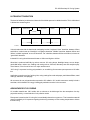
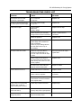
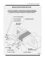
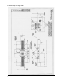
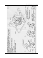
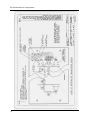
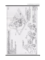
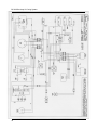
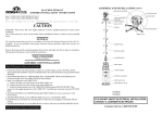
Benchtop UV Curing System Installation and User Manual CAUTION: ULTRAVIOLET LAMPS EMIT RADIATION THAT IS HARMFUL TO EYES AND SKIN. GREAT CARE SHOULD BE TAKEN TO INSURE THAT PERSONNEL ARE NOT EXPOSED TO DIRECT OR REFLECTED RADIATION. SUITABLE EYE PROTECTION, SUCH AS UVP, INC. UV BLOCKING SPECTACLES OR GOGGLES, SHOULD BE WORN WHEN LAMP IS IN OPERATION. BEFORE CLEANING OR RELAMPING, ALWAYS TURN THE POWER OFF. 81-0180-01 Rev A BC-300 Benchtop UV Curing System ULTRAVIOLET RADIATION The band of radiation just below the violet end of the visible spectrum is called ultraviolet. This invisible band is divided into several regions. COSMIC RAYS GAMMA RAYS ULTRAVIOLET VISIBLE INFRA-RED RADIO WAVES X-RAYS --- GERMICIDAL ----- BLACKLIGHT --- -------------- SCHUMAN ---------------X-RAYS 1.0 100 -------------- ERYTHEMAL -------------200 300 400 VISIBLE Various bands exist with the lower band overlapping into the X-ray band. Near ultraviolet, between 320nm and 440nm, is also known as blacklight or longwave ultraviolet. Middle ultraviolet, between 280nm and 320nm, is called erythemal or sun tan ultraviolet. Far ultraviolet, between 300nm and 400nm, is known as germicidal ultraviolet. Industrial UV curing ultraviolet extends lower to 180nm and higher to 420nm. Ultraviolet is produced artificially by various sources: UV curing lamps, blacklight lamps, sun tan lamps, germicidal lamps, carbon arcs, welding and cutting torches, furnaces, laboratory test and analysis equipment. Nature, in the form of the sun is a major natural source. UV Curing is a process involving polymerization, or crosslinking of monomers upon exposure to UV radiation. Applications comprise curing of printing inks, curing coatings for wood and paper, particleboard fillers, metal coatings, adhesives, and prepegs. All monomers do not polymerize when exposed to UV radiation. UV curable monomers usually include a sensitizer, which absorbs UV energy initiating polymerization reaction in the monomer. ADVANTAGES OF UV CURING UV curable materials are 100% solids, with no solvents to be discharged into the atmosphere. As they polymerize entirely, a noted reduction in air pollution results. Plant space is saved, as the UV curing line is considerably shorter than a gas oven. Time is saved as material reacts immediately to UV exposure negating the time lag necessary to raise coating temperature to induce thermal curing. 1 BC-300 Benchtop UV Curing System Lower number of processing and handling procedures provide labor savings. Printed matter is ready for cutting and folding after UV processing. Wood and particleboard panels can be stacked and processed immediately. UV curing lamps, placed between stations in multi-color offset printing, cure one color before next color is applied, eliminating color bleed, scratches, scuffs, etc. Controlled temperature can be obtained where UV curing is used on heat sensitive substrates. Rate or speed of UV curing is affected by the following: • UV curable compounds vary in composition. The type and amount of sensitizer, type and amount of pigment, etc. used in UV curable formulations will dictate UV curing speed. • UV curing time is not directly proportional to coating thickness. A two-fold thickness requires 10 times the radiation energy of a single thickness. UV energy received inside a layer of coating decreases exponentially with depth. • UV curing time will rise with the increase of UV energy per unit surface, up to the saturation point. This is not linear. The curing rate of most monomers, in the presence of air, at a rate greater than the increase in UV energy per unit surface. If the amount of UV energy per unit surface is doubled, curing speed may be tripled, quadrupled, or even rise ten-fold. Two lamps of even power will not cause a cure as quickly as one UV lamp with twice the radiation power. One lamp with twice the power doubles the energy radiated to the same surface and curing speed will double. UV curing lamps with the highest power-to-size ratio should be sued. The non-linear relation between curing rate and UV energy dictates the UV processor reflector design. Focused reflectors, incorporated in UVP, Inc. processors, concentrate the UV energy on a small surface, rather than a uniform distribution over a larger surface. • Various UV sensitizers require different ranges of UV wavelength for proper reaction. Sensitizers should react to UV in a range other than those absorbed by the monomer or pigment. UVP, Inc. medium pressure Mercury lamps emit UV (180nm to 420nm), suitable for all UV curing applications. BENCHTOP CURING SYSTEM SPECIFICATIONS UVP processors consist of the following: 1. High Intensity UV Source (Lamp) 2. Irradiators (Lamp Housing and Reflector Assembly) 3. Shielding, Cooling, and Safety Equipment 4. Power Supply and Electrical Controls Technical Data • • • • • 2 Length: 30, width: 24, height: 18, weight 100 lbs. Central located exhaust fan Optical shielding 1-100 FPM variable speed control with FPM indicator Elasped-time indicator • • • • • • Elliptical focused heat sink reflector 6, 300W/inch curing lamp Nomex-coated fiberglass belt Vacuum hold-down Tri-power lamp switching (300, 200, 125W/inch) 8, 14/3 grounded electric cord BC-300 Benchtop UV Curing System Part Numbers Model BC-300 BC-300 BC-300 Part Number 95-0194-01 95-0194-02 95-0194-03 Watts 300 300 400 Volts 120V/60Hz 220V/50Hz (CE Certified) 220V/50Hz (CE Certified) GENERAL INSTRUCTIONS 1. After unpacking, check all electrical connections and mounting hardware to insure there is no damage. 2. If all items appear satisfactory, install ultraviolet lamp (see Lamp Installation Instructions sheets page 4). 3. to install the drop off plate on each of the curing system, refer to the Installation of Drop Off Plate under Diagrams (see sheet 1979-13). 3. A) Main power and lamp on switch to OFF position. B) High/low lamp intensity (1/2) switch to high position. C) 300 WPI systems - switch to 300 WPI setting. D) Variable speed control knob to ZERO. 4. Plug input cord into Grounded, 120 Volt 60 Hertz, 10 Amps A.C. Outlet. Do not remove ground contact from power cord under any circumstances. 5. Switch Main Power switch to on position. This switch sends power to the lamp switch variable speed control and activates center lamp cooling fan. CAUTION: When fixture is operating, ultraviolet rays are emitted which are harmful to eyes and skin. Great care should be taken to insure personnel are not exposed to direct or reflected radiation. Suitable eye protection, such as UVP UV Blocking Spectacles or Goggles should be employed when lamp is in operation. 6. When shielding is in place and/or operators are utilizing ultraviolet absorbing safety glasses, the lamp switch may be turned on. This will light the ultraviolet lamp. The lamp requires a 3-4 minute warm-up prior to curing applications. 7. Start conveyor belt moving. Belt should always be moving when lamp is on. 8. High/Low lamp intensity option may be utilized to operate lamp at idle mode when curing application are on hold. Lamp will operate at approximately 1/2 the rated output and rapidly return to full power. On tripower models switch lamp to 125 WPI when curing applications are on hold. 9. Shut-Down Procedure: A. B. C. D. E. High/Low lamp intensity switch to high position. Tri-Power models intensity switch to 300 WPI. Lamp switch to off position. Reduce belt speed. Allow main switch to operate cooling fan for 3-5 minutes before total shutdown. This will allow lamp to cool evenly and will prolong lamp life. F. Main power switch to off position. 3 BC-300 Benchtop UV Curing System Lamp Installation and Relamp Instructions A drawing illustrating the lamp installation is included under the Diagrams section (see sheet 1874 1 of 4). 1. Turn power OFF. 2. Disconnect Hi-Voltage cable from irradiator cover. Refer to Wiring Diagram drawing number 1871. 3. Remove lamp irradiator cover by removing the 2 screws at each and of irradiator. 4. Place irradiator on its handles. 5. Remove top lampholder bracket from each side of lamp. 6. Side opposite the connector, remove aluminum cover and ceramic washer. 7. Slide lamp out. 8. When installing lamp, slide lamp between ceramic washer and aluminum holder. Use gloves to prevent fingerprints on lamp. 9. Replace aluminum holder and ceramic washer to assembly. 10. Center lamp so lamp ends are equally spaced on large lampholder bracket. 11. Replace top lampholder brackets, tightening each side equally. Clean lamp a with dry cloth and alcohol. 12. Replace assembly into side extrusion and secure with the 4 screws. 13. Re-connect Hi-Voltage connector. 14. Return to Step 3 of General Instructions. CAUTION: When fixture is operating, ultraviolet rays are emitted which are harmful to eyes and skin. Great care should be taken to insure personnel are not exposed to direct or reflected radiation. Suitable eye and skin protection, such as UVPs UV Blocking Spectacles or Goggles should be employed when lamp is in operation. BEFORE CLEANING OR RELAMPING, TURN POWER OFF. Non-Focused Lamp Installation Instructions A drawing illustrating the lamp installation is included under the Diagrams section (see sheet 1874 3 of 4). 1. Turn power off. 2. Disconnect all power and high voltage cable to irradiator cover. 3. Remove lamp irradiator cover by removing the (2) 10-32 knobs at each end of the irradiator. 4. Place the irradiator upside down on its handles. 5. Refer to drawing 1874 sheet 3 of 4 (see Diagrams section). 4 BC-300 Benchtop UV Curing System 6. Note: metal air diffuser used only with 4, 6 lamp assemblies and laboratory conveyorized system. A. Remove one metal air diffuser. Clean the UV lamp and reflectors with a lint free cloth and denatured isopropyl alcohol (we recommend the use of disposable latex or vinyl gloves to keep the lamp free of fingerprints which will burn into the lamp or liners and create hot spots, disallowing the transmission of the UV rays.) B. Place one wire & ceramic end of the lamp through the mounted metal air diffuser and on top of the lampholder. Place the loose metal air diffuser around the other lamp end and place the lamp end onto the lampholder. C. Remount metal air diffuser with 8-32 x 3/16 screws. Remove the non-focused bracket and the 8/32 x 1/2 screws from the package. At one end feed the wire ceramic end through the lager hole in the non-focus bracket. Mount non-focus bracket to the lampholder with the 8/32 x 1/2 screws provided. Mount the wire lead from the lamp end to the ceramic stand off and replace the 8-32 nut. Repeat on opposite end. 7. Place the irradiator back in place and tighten the (4) 10-32 knobs. Reconnect the high voltage cable by matching index insuring proper connection and screw connector cable down completely. CAUTION: when fixture is operating, ultraviolet rays are emitted which are harmful to eyes and skin. Great care should be taken to insure personnel are not exposed to direct or reflected radiation. Suitable eye and skin protection, such as uvps uv blocking spectacles or goggles should be worn when lamp is in operation. Before cleaning or relamping, ALWAYS TURN POWER OFF. Focused Lamp Installation Instructions 1. Turn Power Off. 2. Disconnect all power and high voltage cable to irradiator cover. 3. Remove lamp irradiator cover by removing the (2) 10-32 knobs at each end of the irradiator. 4. Place the irradiator upside down on its handles. 5. Refer to drawing 1874 sheet 1 of 4 (see Diagrams section). 6. NOTE: mertal air diffuser use only with 4, 6 lamp assemblies and laboratory conveyorized system. A. Remove one metal diffuser. Loosen the 8-32 screws on the lampholder to release the top bracket. Do not remove the bracket--this will swing away. Clean the UV lamp and reflectors with a lint free cloth and denatured isopropyl alcohol (we recommend the use of disposable latex or vinyl gloves to keep th elamp free of ingerprints which will burn into the lamp or liners and create hotspots, disallowing the transmission of the UV rays). B. Place one wire and ceramic end of the lamp through the mounted metal air diffuser and on top of the lampholder. Place the loose metal air diffuser around the other lamp end and place the lamp end onto the lampholder. 5 BC-300 Benchtop UV Curing System C. Remount the metal air diffuser with 8-32x3/16 screws. Place the top bracket over the lamp end and tighten both screws. Mount the wire lead from the lamp end to the ceramic standoff and replace the 8-32 nut. Repeat on the oppositve side of the lamp. 7. Place the irradiator back in place and tighten the (4) 10-32 knobs. Reconnect the high voltage cable by matching index to index insuring proper connection and screw connector cable down completely. CAUTION: When the fixture is opeating, ultraviolet rays are emitted which are harmful to eyes and skin. Great care should be taken to insure personnel are not exposed to direct or reflected radiation. Suitable eye and skin protection, such as UVP UV Blocking Spectacles and Goggles should be worn when the lamp is in operation. Before cleaning or relamping, ALWAYS TURN POWER OFF. REPLACEMENT PARTS AND TECHNICAL SUPPORT Contact UVP for a list of replacement parts for the BC-300 Benchtop Curing System. UVP offers technical support for all of its products. If you have any questions about the products use, operation or repair, contact our offices below. NOTE: A Returned Goods Authorization (RGA) number must be obtained from UVP Customer Service before returning a product to UVP. UVP, Inc. 2066 W. 11th Street Upland, CA 91786 Tel: (800) 452-6788 or (909) 946-3197 Fax: (909) 946-3597 E-Mail: [email protected] Ultra-Violet Products Ltd. Unit 1, Trinity Hall Farm Estate Nuffield Road Cambridge CB4 1TG UK Tel: +44(0) 1223-420022 Fax: +44(0) 1223-420561 E-Mail: [email protected] TROUBLE SHOOTING AND PRODUCT DIAGRAMS A troubleshooting check list for 208/220/420/440 volt 50/60 hertz conveyorized curing system models is shown on page 7. NOTE: Because of the high voltage used throughout the power supply, only qualified personnel should work on it. Wiring Diagrams, Lamp Installation Instruction Sheets, and Installation of Drop Off Plate are provided on the following pages. 6 BC-300 Benchtop UV Curing System TROUBLESHOOTING CHECK LIST PROBLEM CHECK SOLUTION House power on but no belt movement or panel lights F1 in control box 5 Amp fuse Replace fuse Control box and belt working but no control power to power supply F1 in rear of power supply 5 Amp fuse Replace fuse Lamp does not light Lamp condition Main fuses Primary voltage Replace fuses or lamp Check all primary and secondary wiring for burnt or loose connections Repair or replace wires or connectors Check all capacitors Replace if bad Check high voltage cable in rear of power supply and in irradiator for loose connections Check for proper seating between the male and female on top of the irradiator Replace if needed Check DC output from SCR in control box terminal block A+, A-. If no DC output, check all AC input to SCR. If AC input with no DC output, replace SCR Check at motor for DC power. If you have power remove motor from chain and try with no load. If it does not run, replace. Replace motor If it does move, check chain and drive for loose or broken parts Repair as needed Check fuses F2, F3 in control box Replace if blown With blower switch on, check for power at blower receptacle Replace switch or receptacle as needed If blower receptacle has power, check blower cord and connections. If OK, replace motor. Replace motor if needed Lamp comes on but secondary ammeter does not drop to proper reading after 5 minutes Check lamp condition and hours Replace lamp Lamp will not come up to full power and start up Check for bad capacitor. Check for mercury relay stuck in open position Replace if needed Lamp intensity will not change using rotary switch With power off, check mercury relays. They are normally closed. Replace relays if needed Conveyor motor will not start Vacuum blower will not run 7 BC-300 Benchtop UV Curing System 8 BC-300 Benchtop UV Curing System 9 BC-300 Benchtop UV Curing System 10 BC-300 Benchtop UV Curing System 11 BC-300 Benchtop UV Curing System 12 BC-300 Benchtop UV Curing System 13 BC-300 Benchtop UV Curing System 14 BC-300 Benchtop UV Curing System 15 BC-300 Benchtop UV Curing System 16 BC-300 Benchtop UV Curing System 17 BC-300 Benchtop UV Curing System 18 BC-300 Benchtop UV Curing System LIMITED WARRANTY UVPs quality products are guaranteed to be free of defects in material and workmanship for one (1) year from date of shipment under the conditions of normal usage and service. However, double shift operations limit the warranty to six months and twenty-four (24) hour operations limit the warranty to 90 days. If product failure or malfunction occurs during the warranty period, UVP shall examine the inoperative product and have the option to repair or replace any components, which, in the judgment of UVP, were originally defective or become so under conditions of normal usage and service. Customers must first obtain Returned Goods Authorization number (RGA#) from UVP prior to making any returns. The components or product must shipped freight prepaid insured, to UVP Inc., 2066 W. 11th Street, Upland, CA 91786. No warranty shall apply to any products, or component of it, which has been subject to accident, negligence, altercation, abuse or misuse by the end-user. No warranty is offered on components or service supplied by a source other than UVP except for those in strict compliance with the instructions outlined in the end-users operational manual. Ultraviolet Curing lamps are warranted on a prorated basis based on 1,000 hours of usage. When lamps are used at 300 WPI constantly, warranty is for 750 hours. Consequential damages, lost time, inconveniences or contingent liabilities are not covered by this warranty. Repair time is based open the availability of labor, and all parts and components required to make the repair, UVP is not responsible or liable for any personal injuries occurring because of the use, installation and/or servicing of products. All labor, travel costs and sustenance, for service technicians, is the purchasers responsibility. Expendable components such as conveyor belts, UV Lamps, or fuses are not covered by this warranty. CAUTION ULTRAVIOLET LAMPS EMIT RADIATION THAT IS HARMFUL TO EYES AND SKIN. GREAT CARE SHOULD BE TAKEN TO INSURE THAT PERSONNEL ARE NOT EXPOSED TO DIRECT OR REFLECTED RADIATION. SUITABLE EYE PROTECTION, SUCH AS UVP, INC. UV BLOCKING SPECTACLES OR GOGGLES, SHOULD BE WORN WHEN LAMP IS IN OPERATION. BEFORE CLEANING OR RELAMPING, ALWAYS TURN POWER OFF. 19 BC-300 Benchtop UV Curing System Other quality products from UVP: UV Intensity Meters, UV Blocking Eyewear, Handheld Ultraviolet Lamps, High Intensity Ultraviolet Lamps, Display and Bench UV Lamps, UV Transilluminators, UV Crosslinkers UVP, Inc. 2066 W. 11th Street, Upland, CA 91786 Tel: (909) 946-3197 (800) 452-6788 Fax: (909) 946-3197 E-Mail: [email protected] Ultra-Violet Products Ltd. Unit 1, Trinity Hall farm Estate, Nuffield Road Cambridge CB4 1TG UK Tel: +44(0)1223-420022 Fax: +44(0)1223-420531 E-Mail: [email protected] 20